
A Comprehensive Review of Partial Power Converter Topologies and Control Methods for Fast Electric Vehicle Charging Applications


Abstract
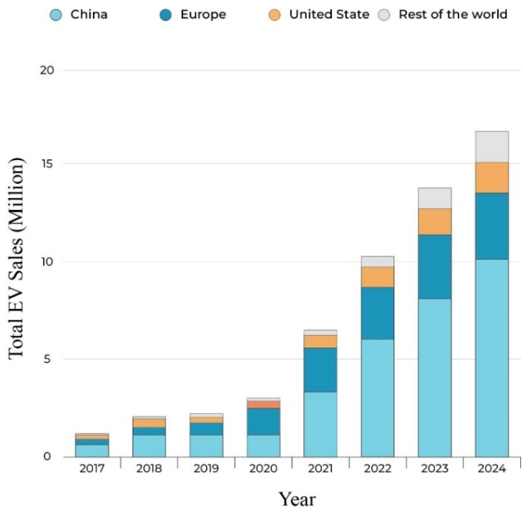
1. Introduction
2. State of the Art and Architecture of EV Charging Station
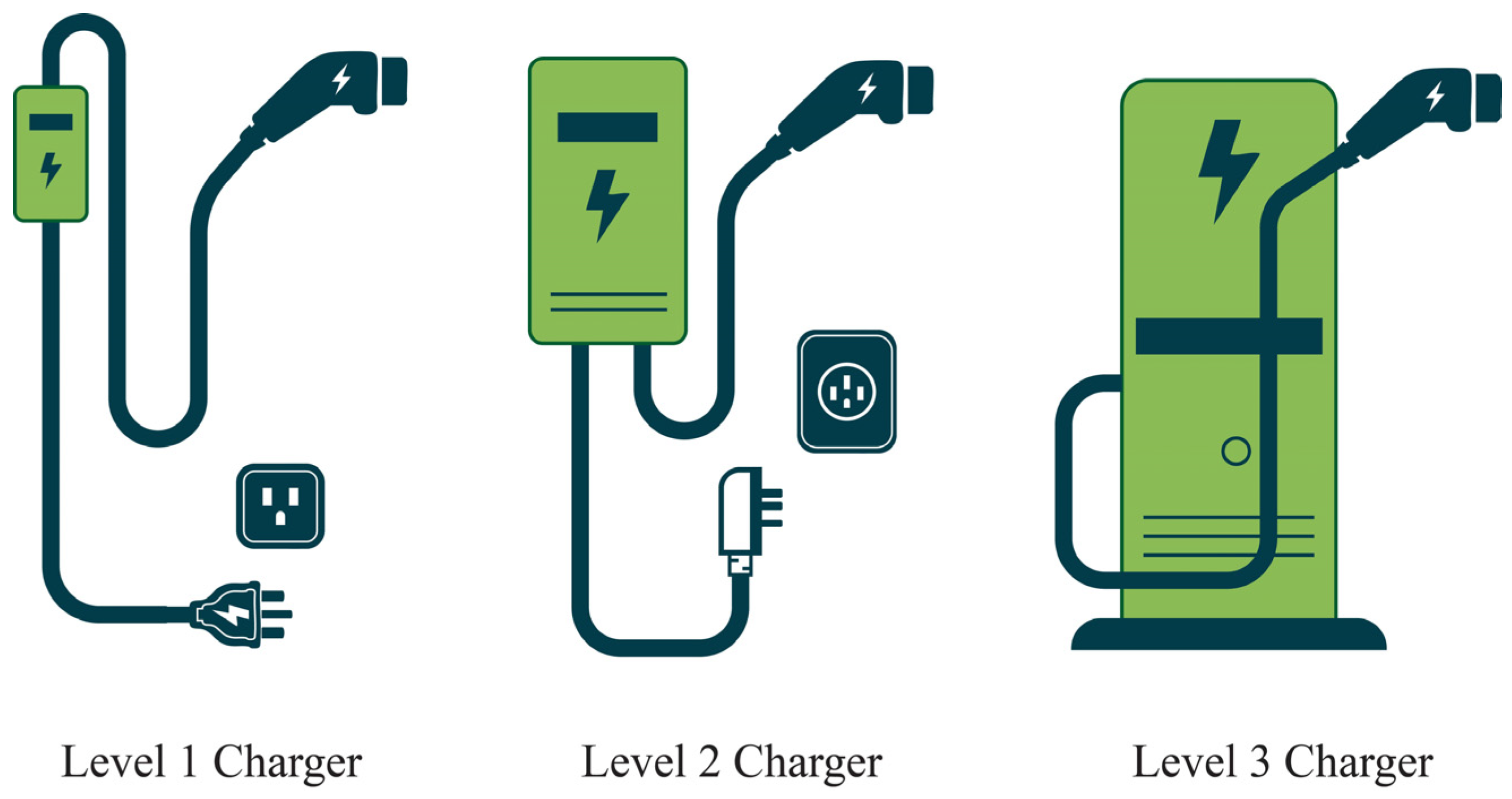
- Level-1 charging is the slowest form of EV charging, typically used in residential settings where overnight charging is sufficient. It operates on standard household voltage (120 V or 230 V) and delivers about 1.92 kW, making it ideal for users with short daily commutes or those who can afford longer charging times. It is most practical for vehicles to remain plugged in overnight to recharge fully. However, its low power output makes it unsuitable for long-distance travel [40,41].
- In contrast, Level-2 charging provides significantly faster speeds, with power levels up to 20 kW, making it suitable for both residential installations and commercial locations like malls and offices, using a higher input voltage of 208 V or 240 V. While it offers a practical solution for frequent users, the limitations of on-board chargers mean it can still take several hours to fully recharge, making it ideal for settings where vehicles are parked for extended periods [42,43].
- Level-3, or DC fast charging, represents a significant leap in charging speed and efficiency, capable of delivering power between 50 kW and 300 kW, allowing EVs to charge up to 80% in as little as 30 min by providing direct current (DC) to the battery and bypassing the onboard charger [40,44,45], typically found in public charging stations along highways, using connectors like Tesla Supercharger.
- Ultra-fast DC charging, capable of delivering 400 kW or more, enables a full charge in just 10 min, reducing range anxiety for long trips. However, it presents challenges in managing large power flows, developing infrastructure, and maintaining battery health. Despite these issues, it is crucial to make electric vehicles competitive with traditional vehicles in terms of refueling convenience. Each charging level serves a vital role, offering solutions from slow, residential charging to fast charging for long-distance travel [40,46].
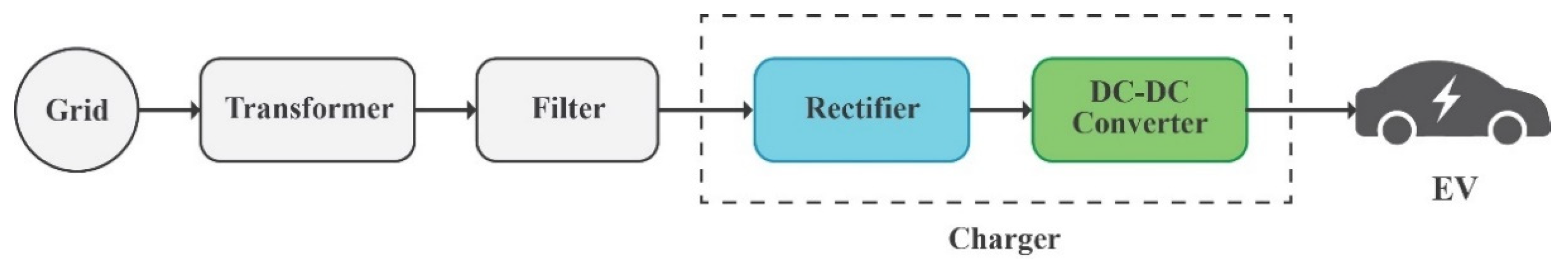
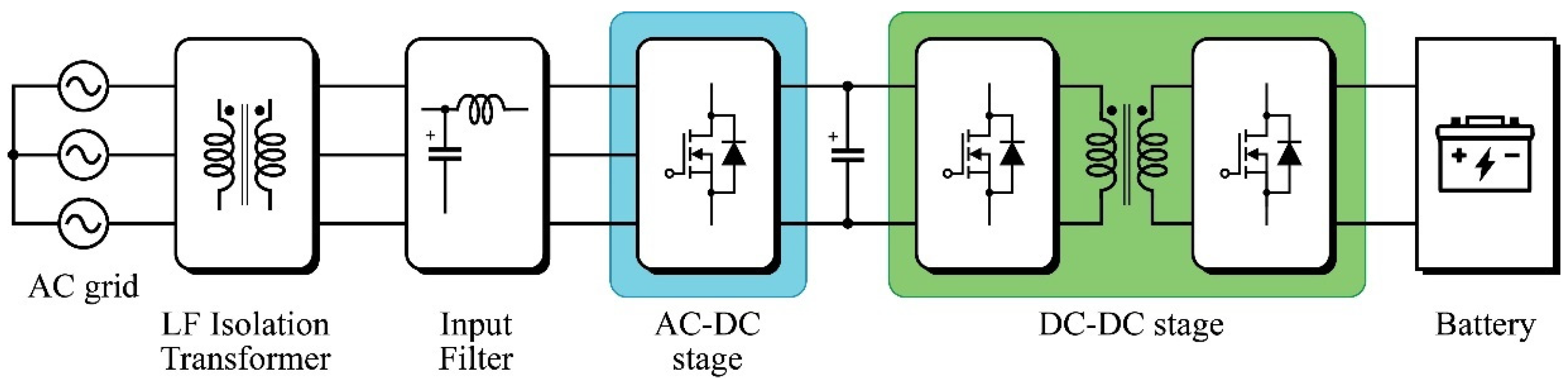
2.1. AC Connected Fast Charging System
2.2. DC Connected Fast Charging System
3. Partial Power Converter (PPC)
4. Partial Power Converter Topologies
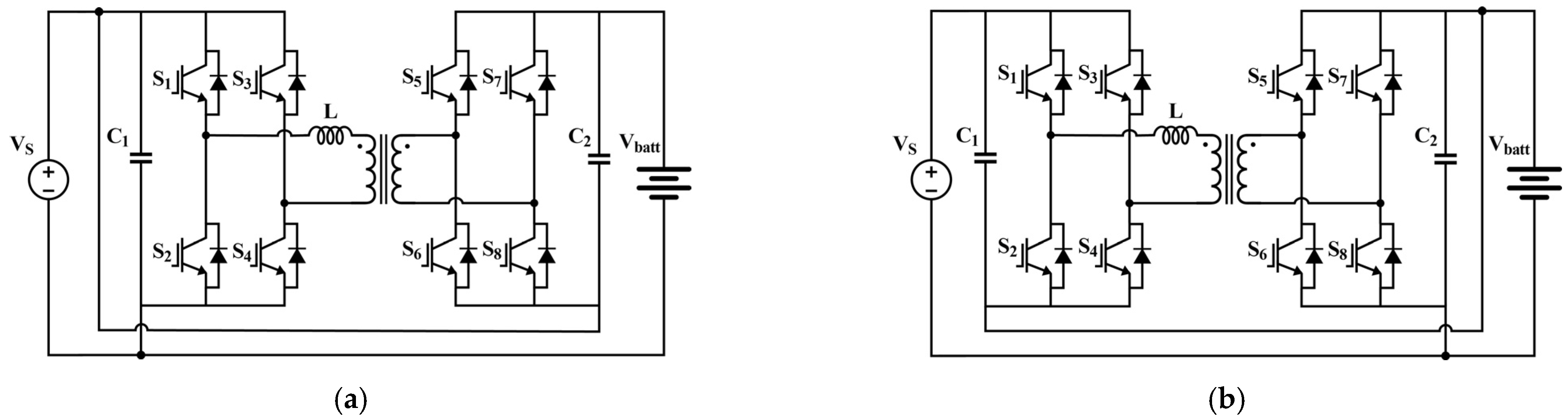
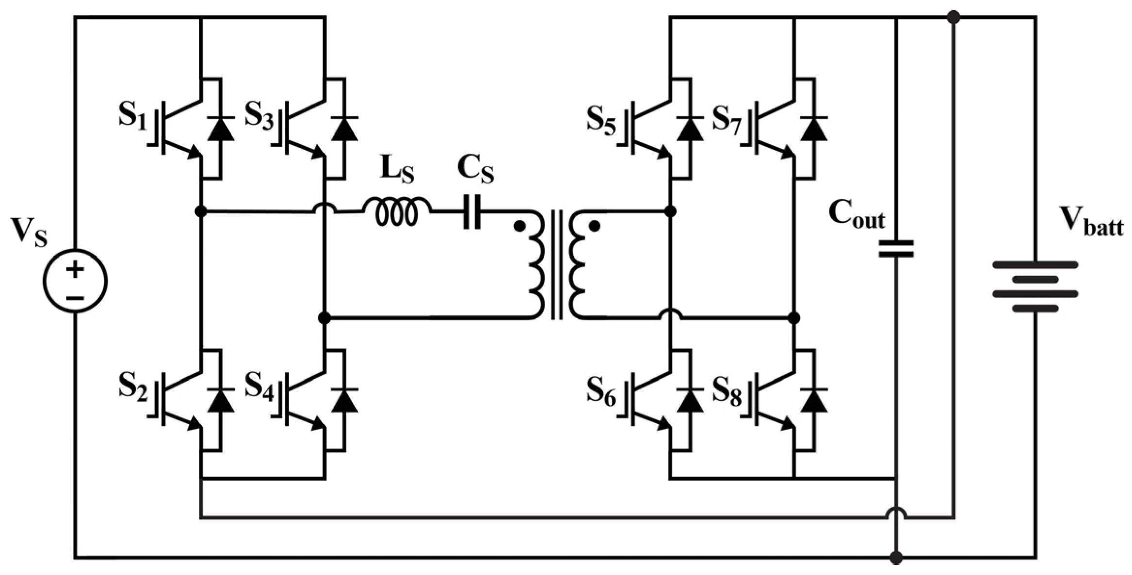
4.1. Partial Power Dual Active Bridge Converter Topologies
4.2. Partial Power Full-Bridge Converter Topologies
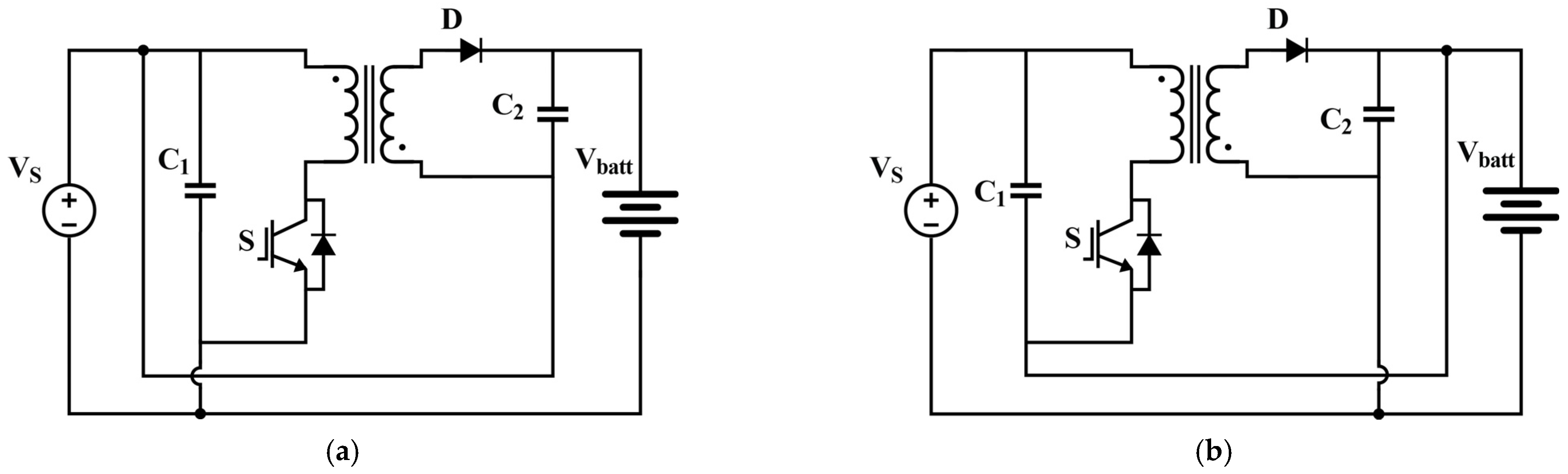
4.3. Partial Power Flyback Converter Topologies
4.4. Partial Power Interleaved Converter Topologies
4.5. Multi-Port Partial Power Converters
4.6. Inductive Power Transfer (IPT) Based Converters
4.7. Cascaded Conversion Topologies
4.8. Solid-State Transformer (SST) Based Converters
4.9. Other Partial Power Converter Topologies
4.9.1. Modular Converters
4.9.2. Partial Processing Zeta Converter
4.9.3. Buck-Boost Converters
4.9.4. Resonant-Type Converters
5. Control Methods for Partial Power Converters
5.1. Control of Partial Power Dual Active Bridge Converter
- Direct inductance current control involves sensing the inductor current and using modulation schemes such as asymmetric double-side modulation. This approach is particularly effective in applications requiring a fast transient response, as the phase shift ratio D can vary dynamically, allowing the DAB converter to adapt quickly to load changes. The fast response time makes it suitable for scenarios with sudden load disturbances. Load current feed-forward control enhances the output transient response by directly accounting for load variations, eliminating the need for an inner current loop and simplifying the control system while maintaining high performance under varying load conditions [85].
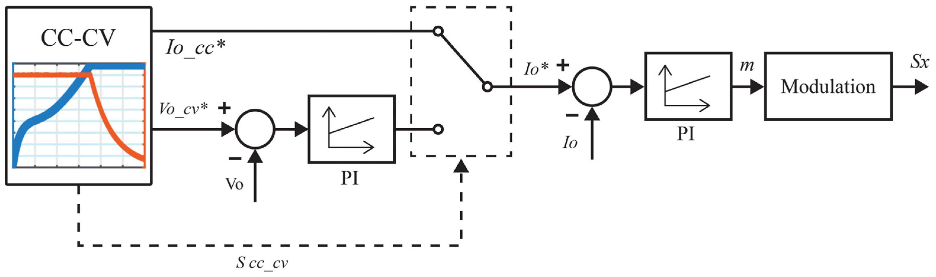
- DPS and TPS modulation extend the ZVS range in DAB converters but lead to large turn-off currents. A combination of SPS, DPS, and TPS helps maintain ZVS across varying voltages while minimizing turn-off losses. Dead band adjustments further extend ZVS from 200 V to 450 V. Before connecting to an EV battery, the output capacitor must be pre-charged under no-load conditions by gradually increasing the reference voltage to match the battery voltage, preventing inrush currents. During pre-charging, the primary voltage appears as a narrow pulse, while the secondary resembles a square waveform, protecting switches from high leakage currents. After pre-charging, the DAB converter transitions through CC, CP, and CV charging modes, managed by PI controllers for smooth operation [86].
5.2. Control of Partial Power Phase-Shifted Full-Bridge Converter
5.3. Control of Partial Power Flyback Converter
5.4. Control of Multi-Port Partial Power Converter
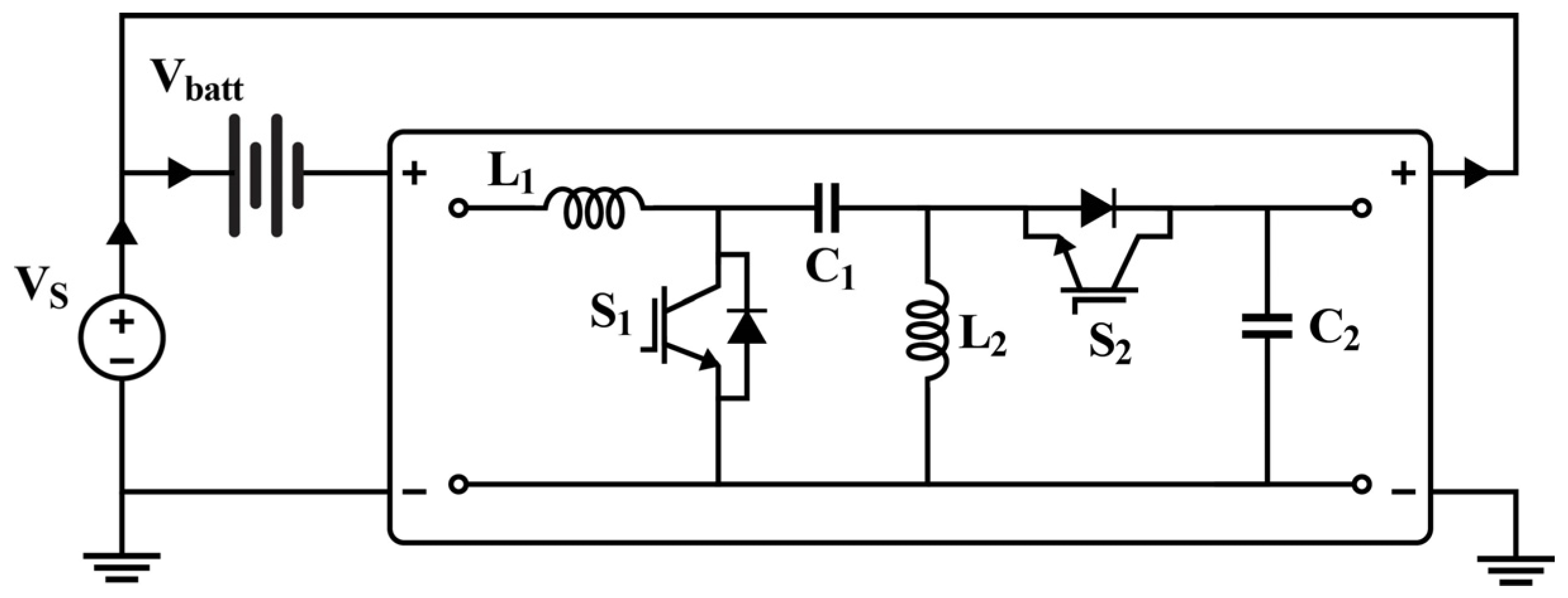
5.5. Control of Buck-Boost Partial Power Converter
6. Architecture and Converter Topology Selection
6.1. Comparison Parameters
6.1.1. Processed Active Power
6.1.2. Semiconductor Stress Analysis
6.1.3. Efficiency
7. Conclusions and Future Directions
Author Contributions
Funding
Data Availability Statement
Conflicts of Interest
Abbreviations
| PPC | Partial Power Converter |
| EV | Electric Vehicle |
| AC | Alternating Current |
| DC | Direct Current |
| PPP | Partial Power Processing |
| FPP | Full Power Processing |
| FPPC | Full Power Processing Converter |
| DPC | Differential Power Converters |
| ESS | Energy Storage Systems |
| MPC | Multiport Power Converters |
| PV | Photovoltaic |
| BESS | Battery Energy Storage System |
| CSS | Combined Charging System |
| IPOS | Input-Parallel-Output-Series |
| ISOP | Input-Series-Output-Parallel |
| DAB | Dual Active Bridge |
| HESS | Hybrid Energy Storage System |
| XFC | Extreme Fast Charging |
| SST | Solid-State Transformer |
| PSFB | Phase-Shifted Full-Bridge |
| EMI | Electromagnetic Interference |
| LLC | Inductor-Inductor-Capacitor |
| ZVS | Zero Voltage Switching |
| ZCS | Zero Current Switching |
| CC | Constant Current |
| CV | Constant Voltage |
| SPS | Single Phase-Shift |
| MPC | Model Predictive Control |
| PWM | Pulse Width Modulation |
| PI | Proportional-Integral |
References
- IEA. Greenhouse Gas Emissions from Energy Data Explorer. Available online: https://www.iea.org/data-and-statistics/data-tools/greenhouse-gas-emissions-from-energy-data-explorer (accessed on 4 December 2024).
- Sam, C.A.; Jegathesan, V. Bidirectional integrated on-board chargers for electric vehicles—A review. Sādhanā 2021, 46, 26. [Google Scholar] [CrossRef]
- Sbordone, D.; Bertini, I.; Di Pietra, B.; Falvo, M.C.; Genovese, A.; Martirano, L. EV fast charging stations and energy storage technologies: A real implementation in the smart micro grid paradigm. Electr. Power Syst. Res. 2015, 120, 96–108. [Google Scholar] [CrossRef]
- Hawkins, T.R.; Gausen, O.M.; Strømman, A.H. Environmental impacts of hybrid and electric vehicles—A review. Int. J. Life Cycle Assess. 2012, 17, 997–1014. [Google Scholar] [CrossRef]
- Sanguesa, J.A.; Torres-Sanz, V.; Garrido, P.; Martinez, F.J.; Marquez-Barja, J.M. A review on electric vehicles: Technologies and challenges. Smart Cities 2021, 4, 372–404. [Google Scholar] [CrossRef]
- Sun, X.; Li, Z.; Wang, X.; Li, C. Technology development of electric vehicles: A review. Energies 2019, 13, 90. [Google Scholar] [CrossRef]
- IEA. Global EV Outlook. 2024. Available online: https://www.iea.org/reports/global-ev-outlook-2024 (accessed on 18 January 2025).
- Rivera, S.; Kouro, S.; Vazquez, S.; Goetz, S.M.; Lizana, R.; Romero-Cadaval, E. Electric vehicle charging infrastructure: From grid to battery. IEEE Ind. Electron. Mag. 2021, 15, 37–51. [Google Scholar] [CrossRef]
- Krishna, G. Understanding and identifying barriers to electric vehicle adoption through thematic analysis. Transp. Res. Interdiscip. Perspect. 2021, 10, 100364. [Google Scholar] [CrossRef]
- Saw, L.H.; Ye, Y.; Tay, A.A. Integration issues of lithium-ion battery into electric vehicles battery pack. J. Clean. Prod. 2016, 113, 1032–1045. [Google Scholar] [CrossRef]
- TODOF PLUG-IN. Overcoming Barriers to Deployment of Plug-in Electric Vehicles. Available online: https://nap.nationalacademies.org/catalog/21725/overcoming-barriers-to-deployment-of-plug-in-electric-vehicles (accessed on 14 December 2024).
- Farahani, H.F.; Rabiee, A.; Khalili, M. Plug-in electric vehicles as a harmonic compensator into microgrids. J. Clean. Prod. 2017, 159, 388–396. [Google Scholar] [CrossRef]
- Dharmakeerthi, C.; Mithulananthan, N.; Saha, T.K. Overview of the impacts of plug-in electric vehicles on the power grid. In Proceedings of the 2011 IEEE PES Innovative Smart Grid Technologies, Piscataway, NJ, USA, 5–7 December 2011; IEEE: Piscataway, NJ, USA, 2011; pp. 1–8. [Google Scholar]
- Srdic, S.; Lukic, S. Toward extreme fast charging: Challenges and opportunities in directly connecting to medium-voltage line. IEEE Electrif. Mag. 2019, 7, 22–31. [Google Scholar] [CrossRef]
- Collin, R.; Miao, Y.; Yokochi, A.; Enjeti, P.; Von Jouanne, A. Advanced electric vehicle fast-charging technologies. Energies 2019, 12, 1839. [Google Scholar] [CrossRef]
- Morrissey, P.; Weldon, P.; O’Mahony, M. Future standard and fast charging infrastructure planning: An analysis of electric vehicle charging behaviour. Energy Policy 2016, 89, 257–270. [Google Scholar] [CrossRef]
- Tu, H.; Feng, H.; Srdic, S.; Lukic, S. Extreme fast charging of electric vehicles: A technology overview. IEEE Trans. Transp. Electrif. 2019, 5, 861–878. [Google Scholar] [CrossRef]
- Acharige, S.S.; Haque, M.E.; Arif, M.T.; Hosseinzadeh, N.; Hasan, K.N.; Oo, A.M.T. Review of electric vehicle charging technologies, standards, architectures, and converter configurations. IEEE Access 2023, 11, 41218–41255. [Google Scholar] [CrossRef]
- Anzola, J.; Aizpuru, I.; Romero, A.A.; Loiti, A.A.; Lopez-Erauskin, R.; Artal-Sevil, J.S.; Bernal, C. Review of architectures based on partial power processing for dc-dc applications. IEEE Access 2020, 8, 103405–103418. [Google Scholar] [CrossRef]
- Anzola, J. Partial Power Converters for DC-DC Applications. 2023. Available online: https://ebiltegia.mondragon.edu/bitstream/handle/20.500.11984/6141/AnzolaGarciaJon_tesis.pdf?sequence=1&isAllowed=y (accessed on 27 January 2025).
- Santos, N.G.F.D.; Zientarski, J.R.R.; da Silva Martins, M.L. A review of series-connected partial power converters for DC–DC applications. IEEE J. Emerg. Sel. Top. Power Electron. 2021, 10, 7825–7838. [Google Scholar] [CrossRef]
- Kwon, Y.D.; Freijedo, F.; Wijekoon, T.; Liserre, M. Partial power processing DC/DC MPPT Converters in Solar PV applications: Overview of Architectures. In Proceedings of the 2022 IEEE 13th International Symposium on Power Electronics for Distributed Generation Systems (PEDG), Kiel, Germany, 26–29 June 2022; IEEE: Piscataway, NJ, USA, 2022; pp. 1–6. [Google Scholar]
- Zientarski, J.R.R.; da Silva Martins, M.L.; Pinheiro, J.R.; Hey, H.L. Evaluation of power processing in series-connected partial-power converters. IEEE J. Emerg. Sel. Top. Power Electron. 2018, 7, 343–352. [Google Scholar] [CrossRef]
- Gsous, O.; Rizk, R.; Barbón, A.; Georgious, R. Review of DC-DC Partial Power Converter Configurations and Topologies. Energies 2024, 17, 1496. [Google Scholar] [CrossRef]
- Verbytskyi, I.; Lukianov, M.; Nassereddine, K.; Pakhaliuk, B.; Husev, O.; Strzelecki, R.M. Power Converter Solutions for Industrial PV Applications—A Review. Energies 2022, 15, 3295. [Google Scholar] [CrossRef]
- Harrison, S.; Soltoswski, B.; Pepiciello, A.; Henao, A.C.; Farag, A.Y.; Beza, M.; Xu, L.; Egea-Àlvarez, A.; Cheah-Mañé, M.; Gomis-Bellmunt, O. Review of multiport power converters for distribution network applications. Renew. Sustain. Energy Rev. 2024, 203, 114742. [Google Scholar] [CrossRef]
- Safayatullah, M.; Elrais, M.T.; Ghosh, S.; Rezaii, R.; Batarseh, I. A comprehensive review of power converter topologies and control methods for electric vehicle fast charging applications. IEEE Access 2022, 10, 40753–40793. [Google Scholar] [CrossRef]
- Khalid, M.; Ahmad, F.; Panigrahi, B.K.; Al-Fagih, L. A comprehensive review on advanced charging topologies and methodologies for electric vehicle battery. J. Energy Storage 2022, 53, 105084. [Google Scholar] [CrossRef]
- Arif, S.M.; Lie, T.T.; Seet, B.C.; Ayyadi, S.; Jensen, K. Review of electric vehicle technologies, charging methods, standards and optimization techniques. Electronics 2021, 10, 1910. [Google Scholar] [CrossRef]
- Mastoi, M.S.; Zhuang, S.; Munir, H.M.; Haris, M.; Hassan, M.; Usman, M.; Bukhari, S.S.H.; Ro, J.S. An in-depth analysis of electric vehicle charging station infrastructure, policy implications, and future trends. Energy Rep. 2022, 8, 11504–11529. [Google Scholar] [CrossRef]
- Zentani, A.; Almaktoof, A.; Kahn, M.T. A comprehensive review of developments in electric vehicles fast charging technology. Appl. Sci. 2024, 14, 4728. [Google Scholar] [CrossRef]
- Suvvala, J.; Dhananjayulu, C.; Kotb, H.; Elrashidi, A. Integration of renewable energy sources using multiport converters for ultra-fast charging stations for electric vehicles: An overview. Heliyon 2024, 10, e35782. [Google Scholar] [CrossRef]
- Shahed, M.T.; Rashid, A.H.-U. Battery charging technologies and standards for electric vehicles: A state-of-the-art review, challenges, and future research prospects. Energy Rep. 2024, 11, 5978–5998. [Google Scholar] [CrossRef]
- Dimitriadou, K.; Rigogiannis, N.; Fountoukidis, S.; Kotarela, F.; Kyritsis, A.; Papanikolaou, N. Current trends in electric vehicle charging infrastructure; opportunities and challenges in wireless charging integration. Energies 2023, 16, 2057. [Google Scholar] [CrossRef]
- Zhang, Y.; Wang, X.; Zhi, B. Strategic investment in electric vehicle charging service: Fast charging or battery swapping. Int. J. Prod. Econ. 2024, 268, 109136. [Google Scholar] [CrossRef]
- Amir, M.; Saifi, I.A.; Waseem, M.; Tariq, M. A critical review of compensation converters for capacitive power transfer in wireless electric vehicle charging circuit topologies. Green Energy Intell. Transp. 2025, 4, 100196. [Google Scholar] [CrossRef]
- Rahulkumar, J.; Narayanamoorthi, R.; Vishnuram, P.; Balaji, C.; Gono, T.; Dockal, T.; Gono, R.; Krejci, P. A review on resonant inductive coupling pad design for wireless electric vehicle charging application. Energy Rep. 2023, 10, 2047–2079. [Google Scholar]
- Khalid, M.R.; Khan, I.A.; Hameed, S.; Asghar, M.S.J.; Ro, J.-S. A comprehensive review on structural topologies, power levels, energy storage systems, and standards for electric vehicle charging stations and their impacts on grid. IEEE Access 2021, 9, 128069–128094. [Google Scholar] [CrossRef]
- Sun, B.; Huang, Z.; Tan, X.; Tsang, D.H. Optimal scheduling for electric vehicle charging with discrete charging levels in distribution grid. IEEE Trans. Smart Grid 2016, 9, 624–634. [Google Scholar] [CrossRef]
- Berrehil El Kattel, M.; Mayer, R.; Ely, F.; de Jesus Cardoso Filho, B. Comprehensive review of battery charger structures of EVs and HEVs for levels 1–3. Int. J. Circuit Theory Appl. 2023, 51, 3514–3542. [Google Scholar] [CrossRef]
- Sears, J.; Roberts, D.; Glitman, K. A comparison of electric vehicle Level 1 and Level 2 charging efficiency. In Proceedings of the 2014 IEEE Conference on Technologies for Sustainability (SusTech), Portland, OR, USA, 24–26 July 2014; IEEE: Piscataway, NJ, USA, 2014; pp. 255–258. [Google Scholar]
- Khan, S.; Shariff, S.; Ahmad, A.; Alam, M.S. A comprehensive review on level 2 charging system for electric vehicles. Smart Sci. 2018, 6, 271–293. [Google Scholar] [CrossRef]
- Khan, S.; Alam, M.S.; Asghar, M.J.; Khan, M.A.; Abbas, A. Recent development in level 2 charging system for xEV: A review. In Proceedings of the 2018 International Conference on Computational and Characterization Techniques in Engineering and Sciences (CCTES), Lucknow, India, 14–15 September 2018; IEEE: Piscataway, NJ, USA, 2018; pp. 83–88. [Google Scholar]
- Falvo, M.C.; Sbordone, D.; Bayram, I.S.; Devetsikiotis, M. EV charging stations and modes: International standards. In Proceedings of the 2014 International Symposium on Power Electronics, Electrical Drives, Automation and Motion, Ischia, Italy, 18–20 June 2014; IEEE: Piscataway, NJ, USA, 2014; pp. 1134–1139. [Google Scholar]
- Chon, S.; Bhardwaj, M.; Nene, H. Maximizing Power for Level 3 EV Charging Stations; Texas Instruments Incorporated: Dallas, TX, USA, 2018; pp. 1–33. [Google Scholar]
- ElMenshawy, M.; Massoud, A. Modular isolated dc-dc converters for ultra-fast ev chargers: A generalized modeling and control approach. Energies 2020, 13, 2540. [Google Scholar] [CrossRef]
- Veneri, O.; Ferraro, L.; Capasso, C.; Iannuzzi, D. Charging infrastructures for EV: Overview of technologies and issues. In Proceedings of the 2012 Electrical Systems for Aircraft, Railway and Ship Propulsion, Bologna, Italy, 16–18 October 2012; IEEE: Piscataway, NJ, USA, 2012; pp. 1–6. [Google Scholar]
- Purushothaman, D.; Narayanamoorthi, R.; Elrashidi, A.; Kotb, H. A comprehensive review on single-stage WPT converter topologies and power factor correction methodologies in EV charging. IEEE Access 2023, 11, 135529–135555. [Google Scholar] [CrossRef]
- Patel, N.; Lopes, L.A.; Rathore, A.K.; Khadkikar, V. High-efficiency single-stage single-phase bidirectional pfc converter for plug-in ev charger. IEEE Trans. Transp. Electrif. 2023, 10, 5636–5649. [Google Scholar] [CrossRef]
- Zinchenko, D.; Blinov, A.; Chub, A.; Vinnikov, D.; Verbytskyi, I.; Bayhan, S. High-efficiency single-stage on-board charger for electrical vehicles. IEEE Trans. Veh. Technol. 2021, 70, 12581–12592. [Google Scholar] [CrossRef]
- Pho, B.B.; Manh, T.N.; Do, T.A.; Vu, P. Three-Phase Single-Stage AC-DC Converter of EV Charging System with Reduced Device Count. In Proceedings of the International Conference on Intelligent Systems and Networks, Hanoi, Vietnam, 19 March 2024; Springer: Cham, Switzerland, 2024; pp. 285–294. [Google Scholar]
- Muttaqi, K.M.; Isac, E.; Mandal, A.; Sutanto, D.; Akter, S. Fast and random charging of electric vehicles and its impacts: State-of-the-art technologies and case studies. Electr. Power Syst. Res. 2024, 226, 109899. [Google Scholar] [CrossRef]
- Zayed, O.; Elezab, A.; Abuelnaga, A.; Narimani, M. A Dual-Active Bridge Converter With a Wide Output Voltage Range (200–1000 V) for Ultrafast DC-Connected EV Charging Stations. IEEE Trans. Transp. Electrif. 2022, 9, 3731–3741. [Google Scholar] [CrossRef]
- Chakraborty, S.; Vu, H.-N.; Hasan, M.M.; Tran, D.-D.; Baghdadi, M.E.; Hegazy, O. DC-DC converter topologies for electric vehicles, plug-in hybrid electric vehicles and fast charging stations: State of the art and future trends. Energies 2019, 12, 1569. [Google Scholar] [CrossRef]
- Yahaya, A.A.; Edpuganti, A.; Khadkikar, V.; Zeineldin, H. A Novel Simultaneous AC and DC Charging Scheme for Electric Vehicles. IEEE Trans. Energy Convers. 2024, 39, 1534–1546. [Google Scholar] [CrossRef]
- Rajendran, G.; Vaithilingam, C.A.; Misron, N.; Naidu, K.; Ahmed, M.R. A comprehensive review on system architecture and international standards for electric vehicle charging stations. J. Energy Storage 2021, 42, 103099. [Google Scholar] [CrossRef]
- Iyer, V.M.; Gulur, S.; Gohil, G.; Bhattacharya, S. Extreme fast charging station architecture for electric vehicles with partial power processing. In Proceedings of the 2018 IEEE Applied Power Electronics Conference and Exposition (APEC), San Antonio, TX, USA, 4–8 March 2018; IEEE: Piscataway, NJ, USA, 2018; pp. 659–665. [Google Scholar]
- Button, R.M. An advanced photovoltaic array regulator module. In Proceedings of the IECEC 96. Proceedings of the 31st Intersociety Energy Conversion Engineering Conference, Washington, DC, USA, 11–16 August 1996; IEEE: Piscataway, NJ, USA, 1996; Volume 1, pp. 519–524. [Google Scholar]
- Iyer, V.M.; Gulur, S.; Gohil, G.; Bhattacharya, S. An approach towards extreme fast charging station power delivery for electric vehicles with partial power processing. IEEE Trans. Ind. Electron. 2019, 67, 8076–8087. [Google Scholar] [CrossRef]
- Zientarski, J.R.R.; Pinheiro, J.R.; da Silva Martins, M.L.; Hey, H.L. Understanding the partial power processing concept: A case-study of buck-boost dc/dc series regulator. In Proceedings of the 2015 IEEE 13th Brazilian Power Electronics Conference and 1st Southern Power Electronics Conference (COBEP/SPEC), Fortaleza, Brazil, 29 November–2 December 2015; IEEE: Piscataway, NJ, USA, 2015; pp. 1–6. [Google Scholar]
- Ferreira, H.J.; Kouro, S.; Rojas, C.A.; Muller, N.; Rivera, S. Bidirectional partial power dc-dc configuration for hess interface in ev powertrains. In Proceedings of the 2021 22nd IEEE International Conference on Industrial Technology (ICIT), Valencia, Spain, 10–12 March 2021; IEEE: Piscataway, NJ, USA, 2021; Volume 1, pp. 327–332. [Google Scholar]
- Mishra, S.; Tamballa, S.; Pallantala, M.; Raju, S.; Mohan, N. Cascaded dual-active bridge cell based partial power converter for battery emulation. In Proceedings of the 2019 20th Workshop on Control and Modeling for Power Electronics (COMPEL), Toronto, ON, Canada, 16–19 June 2019; IEEE: Piscataway, NJ, USA, 2019; pp. 1–7. [Google Scholar]
- Beckmann, C.S.; Rojas, C.A.; Renaudineau, H.; Kouro, S.; Young, H.; Opazo, R.; Rivera, S. Comparison of modulation strategies for a dual active bridge partial power DC-DC converter in EV powertrains. In Proceedings of the IECON 2022–48th Annual Conference of the IEEE Industrial Electronics Society, Brussels, Belgium, 17–20 October 2022; IEEE: Piscataway, NJ, USA, 2022; pp. 1–6. [Google Scholar]
- Rivera, S.; Pesantez, D.; Kouro, S.; Lehn, P.W. Pseudo-partial-power converter without high frequency transformer for electric vehicle fast charging stations. In Proceedings of the 2018 IEEE Energy Conversion Congress and Exposition (ECCE), Portland, OR, USA, 23–27 September 2018; IEEE: Piscataway, NJ, USA, 2018; pp. 1208–1213. [Google Scholar]
- Anzola, J.; Artal-Sevil, J.S.; Aizpuru, I.; Arruti, A.; Lopez, R.; Alacano, A.; Bernal-Ruiz, C. Resonant dual active bridge partial power converter for electric vehicle fast charging stations. In Proceedings of the 2021 IEEE Vehicle Power and Propulsion Conference (VPPC), Gijon, Spain, 25–28 October 2021; IEEE: Piscataway, NJ, USA, 2021; pp. 1–6. [Google Scholar]
- Pesantez, D.; Renaudineau, H.; Rivera, S.; Peralta, A.; Alcaide, A.M.; Kouro, S. Transformerless partial power converter topology for electric vehicle fast charge. IET Power Electron. 2024, 17, 970–982. [Google Scholar] [CrossRef]
- Rivera, S.; Rojas, J.; Kouro, S.; Lehn, P.W.; Lizana, R.; Renaudineau, H.; Dragičević, T. Partial-power converter topology of type II for efficient electric vehicle fast charging. IEEE J. Emerg. Sel. Top. Power Electron. 2021, 10, 7839–7848. [Google Scholar] [CrossRef]
- Rivera, S.; Flores-Bahamonde, F.; Renaudineau, H.; Dragicevic, T.; Kouro, S. A buck-boost series partial power converter using a three-port structure for electric vehicle charging stations. In Proceedings of the 2021 IEEE 12th Energy Conversion Congress and Exposition-Asia (ECCE-Asia), Singapore, 24–27 May 2021; IEEE: Piscataway, NJ, USA, 2021; pp. 1749–1754. [Google Scholar]
- Granello, P.; Soeiro, T.B.; Van Der Blij, N.H.; Bauer, P. Revisiting the partial power processing concept: Case study of a 5-kW 99.11% efficient flyback converter-based battery charger. IEEE Trans. Transp. Electrif. 2022, 8, 3934–3945. [Google Scholar] [CrossRef]
- Xu, R.; Gao, S.; Wang, Y.; Xu, D. A high step up SEPIC-based partial-power converter with wide input range. In Proceedings of the 2021 IEEE Industry Applications Society Annual Meeting (IAS), Vancouver, BC, Canada, 10–14 October 2021; IEEE: Piscataway, NJ, USA, 2021; pp. 1–5. [Google Scholar]
- Weldt, N.; Espinoza, J.; Sbarbaro, D.; Morán, L.; Kouro, S. Topologies and control strategies of partial power dc/dc converters for photovoltaic systems. In Proceedings of the IECON 2021–47th Annual Conference of the IEEE Industrial Electronics Society, Toronto, ON, Canada, 13–16 October 2021; IEEE: Piscataway, NJ, USA, 2021; pp. 1–6. [Google Scholar]
- Anzola, J.; Aizpuru, I.; Arruti, A. Non-isolated partial power converter for electric vehicle fast charging stations. In Proceedings of the 2020 IEEE 11th International Symposium on Power Electronics for Distributed Generation Systems (PEDG), Dubrovnik, Croatia, 6 August 2020; IEEE: Piscataway, NJ, USA, 2020; pp. 18–22. [Google Scholar]
- Hoffmann, F.; Person, J.; Andresen, M.; Liserre, M.; Freijedo, F.D.; Wijekoon, T. A multiport partial power processing converter with energy storage integration for EV stationary charging. IEEE J. Emerg. Sel. Top. Power Electron. 2021, 10, 7950–7962. [Google Scholar] [CrossRef]
- Xiong, W.; Yan, Z.; Tang, D.; Zhou, W.; Mai, R. A Hybrid Topology IPT System with Partial Power Processing for CC-CV Charging. IEEE Trans. Power Electron. 2023, 39, 1701–1712. [Google Scholar] [CrossRef]
- Stanojević, A.; Bouvier, Y.E.; Grbović, P.J. Comparison of 2-stage isolated converters for fast EV charger, using partial power. In Proceedings of the IECON 2022–48th Annual Conference of the IEEE Industrial Electronics Society, Brussels, Belgium, 17–20 October 2022; IEEE: Piscataway, NJ, USA, 2022; pp. 1–6. [Google Scholar]
- Zheng, L.; Kandula, R.P.; Divan, D. Multiport control with partial power processing in solid-state transformer for PV, storage, and fast-charging electric vehicle integration. IEEE Trans. Power Electron. 2022, 38, 2606–2616. [Google Scholar] [CrossRef]
- Anzola, J.; Garayalde, E.; Urkizu, J.; Alacano, A.; Lopez-Erauskin, R. High Efficiency Converters Based on Modular Partial Power Processing for Fully Electric Maritime Applications. Electronics 2023, 12, 2778. [Google Scholar] [CrossRef]
- Sundararaman, K.; Alagappan, P.; Elavarasu, R. Partial processing converters for charging electric vehicles. In Proceedings of the 2021 International Conference on Advances in Electrical, Computing, Communication and Sustainable Technologies (ICAECT), Bhilai, India, 19–20 February 2021; IEEE: Piscataway, NJ, USA, 2021; pp. 1–7. [Google Scholar]
- Muñoz, R.V.; Renaudineau, H.; Rivera, S.; Kouro, S. Evaluation of DC-DC buck-boost partial power converters for EV fast charging application. In Proceedings of the IECON 2021–47th Annual Conference of the IEEE Industrial Electronics Society, Toronto, ON, Canada, 13–16 October 2021; IEEE: Piscataway, NJ, USA, 2021; pp. 1–6. [Google Scholar]
- Cao, Y.; Ngo, M.; Yan, N.; Dong, D.; Burgos, R.; Ismail, A. Design and implementation of an 18-kW 500-kHz 98.8% efficiency high-density battery charger with partial power processing. IEEE J. Emerg. Sel. Top. Power Electron. 2021, 10, 7963–7975. [Google Scholar] [CrossRef]
- Hou, N.; Qin, K.; Wei, R.; Zhang, Y.; Li, Y.W. Control techniques with low computational burden for a DAB-based two-stage DC-DC EV charging converter system. IEEE Trans. Power Electron. 2024, 39, 10865–10875. [Google Scholar] [CrossRef]
- Coelho, S.; Monteiro, V.; Afonso, J.L. Topological Advances in Isolated DC–DC Converters: High-Efficiency Design for Renewable Energy Integration. Sustainability 2025, 17, 2336. [Google Scholar] [CrossRef]
- Granello, P.; Schirone, L. Modeling and experimental validation of dual-output flyback converters with capacitive coupling for improved cross-regulation. Electronics 2024, 13, 3503. [Google Scholar] [CrossRef]
- Shao, S.; Chen, L.; Shan, Z.; Gao, F.; Chen, H.; Sha, D.; Dragičević, T. Modeling and advanced control of dual-active-bridge DC–DC converters: A review. IEEE Trans. Power Electron. 2021, 37, 1524–1547. [Google Scholar] [CrossRef]
- Shukla, T.; Baig, M.J.; Ahirwar, K.K.; Raghuwanshi, A.; Ansari, A.A.; Adhikari, A. A bridgeless configured asymmetrical alternating current–direct current converter-based isolated single-stage electric vehicle battery charger with supply side power factor enhancement. IET Electr. Power Appl. 2024, 18, 446–457. [Google Scholar] [CrossRef]
- Wang, N.; Wang, Y.; Chen, Z. A Novel DC-bias Current Suppression Strategy for DAB converter under TPS Modulation. In Proceedings of the 2024 IEEE 10th International Power Electronics and Motion Control Conference (IPEMC2024-ECCE Asia), Chengdu, China, 17–20 May 2024; IEEE: Piscataway, NJ, USA, 2024; pp. 1265–1269. [Google Scholar]
- Huang, J.; Wang, C.; Zhang, Z.; Ouyang, Z.; Zsurzsan, G.; Andersen, M.A. Analysis of Partial Parallel Dual Active Bridge Converter with Additional Phase Shift Control. In Proceedings of the 2022 International Power Electronics Conference (IPEC-Himeji 2022-ECCE Asia), Himeji, Japan, 15–19 May 2022; IEEE: Piscataway, NJ, USA, 2022; pp. 1044–1045. [Google Scholar]
- Song, H.; Xu, R.; Gao, S.; Wang, Y.; Xu, D. A high-frequency dual active bridge converter with partial power processing. In Proceedings of the 2022 IEEE International Power Electronics and Application Conference and Exposition (PEAC), Guangzhou, China, 4–7 November 2022; IEEE: Piscataway, NJ, USA, 2022; pp. 258–263. [Google Scholar]
- Roja, P.; John, V. Asymmetrical Phase-Shifted Full-Bridge Converters in Input-Parallel Output-Parallel Configuration. IEEE Trans. Ind. Appl. 2024, 60, 6435–6445. [Google Scholar] [CrossRef]
- Qin, G.; Ma, H.; Lei, J.; Hao, C. Advanced Control Strategies for Enhancing the Performance of Phase-Shifted Full-Bridge Series Resonant DC–DC Converters in Photovoltaic Micro-Inverters. Energies 2025, 18, 387. [Google Scholar] [CrossRef]
- Franzese, P.; Spina, I.; Attaianese, C.; Iannuzzi, D. Partial Power Processing using a Flyback converter: Design and comparison. In Proceedings of the 2024 International Symposium on Power Electronics, Electrical Drives, Automation and Motion (SPEEDAM), Napoli, Italy, 19–21 June 2024; IEEE: Piscataway, NJ, USA, 2024; pp. 986–993. [Google Scholar]
- Ramos-Paja, C.A.; Bastidas-Rodriguez, J.D.; Saavedra-Montes, A.J. Sliding-mode control of a photovoltaic system based on a flyback converter for microinverter applications. Appl. Sci. 2022, 12, 1399. [Google Scholar] [CrossRef]
- Tlili, F.; Bacha, F. Comparative study based on different switching lookup tables for Direct Power Control of three-phase AC/DC converter. In Proceedings of the 2020 4th International Conference on Advanced Systems and Emergent Technologies (IC_ASET), Hammamet, Tunisia, 15–18 December 2020; IEEE: Piscataway, NJ, USA, 2020; pp. 152–157. [Google Scholar]
- Gunasekaran, K.; Samikannu, R. Thermal analysis of onboard front-end AC/DC converter for EV using advanced semiconductor devices. Results Eng. 2025, 25, 104040. [Google Scholar] [CrossRef]
- Hosseinabadi, F.; Chakraborty, S.; Bhoi, S.K.; Prochart, G.; Hrvanovic, D.; Hegazy, O. A comprehensive overview of reliability assessment strategies and testing of power electronics converters. IEEE Open J. Power Electron. 2024, 5, 473–512. [Google Scholar] [CrossRef]


| Charger Type | Charger Location | Power Supply | Power Level | Charging Time |
|---|---|---|---|---|
| Level 1 (AC) | On-board (Residential charging) | 120/230 Vac; 12 A to 16 A | From 1.44 kW to 1.92 kW | 11–36 h for EVs (16–50 kWh) |
| Level 2 (AC) | On-board (Charging at home or workplace) | 208/240 Vac; 15 A to 80 A | From 3.1 kW to 19.2 kW | 2–6 h for EVs (16–30 kWh) |
| Level 3 (DC Fast) | Off-board (Charging at public places) | 300–600 Vdc (Maximum current 400 A) | From 50 kW to 350 kW | Less than 30 min for EVs (20–50 kWh) |
| DC Ultra-Fast Charging | Off-board (Charging at public places) | 800 Vdc and higher; 400 A and higher | 400 kW and higher | Approximately 10 min for EVs (20–50 kWh) |
| Criteria | AC Connected Charging System | DC Connected Charging System |
|---|---|---|
| Conversion Stages | Higher | Lower |
| Efficiency of System | Lower | Higher |
| Energy Sources Integration | Complex | Easier |
| Load Side Impact | High | Less |
| Control System | Complex | Simple |
| Cost of System | Higher | Lower |
| PPC Topology | Ref. No. | Application | Advancement |
|---|---|---|---|
| Dual Active Bridge Converter Topologies | [61] | EV powertrains, Hybrid Energy Storage Systems (HESS) | Mitigates high current stress enhances power density, improves efficiency |
| [62] | AC/DC microgrids, EV powertrains | Achieves high efficiency, reduces control effort, minimizes downtime | |
| [59] | Extreme Fast Charging (XFC) stations | Improves efficiency by 0.6% at full load, 1.6% at 50% load | |
| [63] | Heavy-duty EV powertrains | Strategic modulation improves efficiency to 99.41% | |
| [64] | EV fast charging | Enhances power density, reduces costs | |
| Full-Bridge Converter Topologies | [66] | EV fast charging stations | Increases power ratings, reduces charging times, enhances reliability |
| [67] | EV fast chargers | Improves efficiency, processes 13.32% of total power | |
| [57] | Extreme Fast Charging (XFC) stations | Improves efficiency, integrates renewable energy sources | |
| [68] | EV fast chargers | Supports both 400 V and 800 V batteries, reaches 98.65% efficiency | |
| [42] | Rapid charging stations | Increases conversion efficiency from 95.1% to 98.3% | |
| Flyback Converter Topologies | [69] | Battery energy storage system (BESS) charging | 99% efficiency in 5 kW charger with series configuration, less stress and filtering |
| [70] | Renewable energy systems with a wide input voltage range | Enhanced voltage gain, better power density, and soft switching | |
| Interleaved Converter Topologies | [71] | EV fast charging stations | Enhances efficiency, reduces processed power |
| [72] | Medium-voltage multiport current-source (CS) solid-state transformers | Reduces DC-link current by 36%, improves efficiency | |
| Multi-Port Converters | [73] | Electric maritime applications | Increases efficiency, enhances modularity and fault-tolerance |
| Inductive Power Transfer Systems | [74] | EV fast charging | Demonstrates 99% efficiency, suitable for fast charging |
| Cascaded Conversion Topologies | [75] | EV fast charging stations | Achieves high efficiency across a wide operating range |
| Solid-State Transformer based Converters | [76] | Constant current (CC) and constant voltage (CV) charging | Improves efficiency, reduces power loss and device stress |
| Modular Converters | [77] | EV charging stations | Achieves high efficiency in battery charging |
| Partial Processing Zeta Converter | [78] | EV fast charging stations | Optimizes gain and transformer turns ratio, reduces RMS currents |
| Buck-Boost Converters | [79] | High-efficiency, high-density battery chargers | Achieves 98.8% efficiency and high power density |
| Resonant-Type Converters | [80] | High-efficiency bidirectional battery charging | Ultra-high efficiency (98.8%) and power density (142 W/in3) |
Disclaimer/Publisher’s Note: The statements, opinions and data contained in all publications are solely those of the individual author(s) and contributor(s) and not of MDPI and/or the editor(s). MDPI and/or the editor(s) disclaim responsibility for any injury to people or property resulting from any ideas, methods, instructions or products referred to in the content. |
© 2025 by the authors. Licensee MDPI, Basel, Switzerland. This article is an open access article distributed under the terms and conditions of the Creative Commons Attribution (CC BY) license (https://creativecommons.org/licenses/by/4.0/).
Share and Cite
Ejaz, B.; Zamora, R.; Reusser, C.; Lin, X. A Comprehensive Review of Partial Power Converter Topologies and Control Methods for Fast Electric Vehicle Charging Applications. Electronics 2025, 14, 1928. https://doi.org/10.3390/electronics14101928
Ejaz B, Zamora R, Reusser C, Lin X. A Comprehensive Review of Partial Power Converter Topologies and Control Methods for Fast Electric Vehicle Charging Applications. Electronics. 2025; 14(10):1928. https://doi.org/10.3390/electronics14101928
Chicago/Turabian StyleEjaz, Babar, Ramon Zamora, Carlos Reusser, and Xin Lin. 2025. "A Comprehensive Review of Partial Power Converter Topologies and Control Methods for Fast Electric Vehicle Charging Applications" Electronics 14, no. 10: 1928. https://doi.org/10.3390/electronics14101928
APA StyleEjaz, B., Zamora, R., Reusser, C., & Lin, X. (2025). A Comprehensive Review of Partial Power Converter Topologies and Control Methods for Fast Electric Vehicle Charging Applications. Electronics, 14(10), 1928. https://doi.org/10.3390/electronics14101928