Abstract
Thanks to the magnetic field modulation effect, the magnetic field modulation motor (MFMM) significantly improves torque density and magnetic field harmonic utilization by breaking the constraints of traditional motor excitation and armature pole number matching. This advantage enhances its development potential in fields such as new energy vehicles, aerospace, power generation, and the military. This article first starts with the basic principle of magnetic field modulation, and adopts the excitation unit position classification method to systematically summarize the evolution laws of major MFMM topology structures such as the permanent magnet synchronous motor, switch magnetic flux motor, and flux reversal motor in recent years. It also analyzes the research progress of key performance such as the torque characteristics and power factor of these motors. Research has pointed out that the MFMM still faces core challenges such as high torque ripple, complex structure, low power factor, and multiple losses. Based on a review of the main achievements in the field, the future development direction of MFMMs is proposed to promote its development in the fields of precision drive and efficient energy conversion.
1. Introduction
As the core equipment for electromechanical energy conversion, motors are widely used in industries, transportation, and other fields. Due to global attention to climate change, they are gradually replacing traditional machinery and hydraulic devices and becoming the core power source in key fields such as national defense, new energy, and aerospace [1]. As the application fields of motors expand, higher requirements have been put forward for their torque density, vibration, control, and heat dissipation performance, which has made structural and principle innovation a research focus [2].
The MFMM is based on the “magnetic field modulation effect” and achieves full utilization of magnetic field harmonics through unequal pole logarithmic armatures, excitation units, and newly added modulation units [3]. This effect endows the motor with a torque amplification function similar to a gearbox, known as the “pole ratio”, thereby providing higher torque density under the same material and demonstrating broad application potential.
Compared with traditional permanent magnet synchronous motors (PMSMs), the core advantage of MFMMs lies in its unique magnetic field modulation mechanism: PMSMs rely on direct magnetic field coupling between the PM and armature winding, with fixed pole pairs and strict matching of power supply frequency, while MFMMs actively regulate magnetic field harmonics through modulation units and use asymmetric pole pair design to achieve torque amplification, significantly improving the torque density. At the same time, the pole ratio of an MFMM can be flexibly designed, breaking through the traditional limit of pole pairs, adapting to a wide range of variable speed requirements, and reducing losses through magnetic field optimization under partial loads. This enables the MFMM to demonstrate higher material utilization and dynamic control capabilities in low-speed, high torque applications (such as electric vehicles, wind power drives), or space limited scenarios.
However, MFMMs face many challenges due to the introduction of modulation units such as complex harmonic coupling mechanisms and performance optimization difficulties caused by diverse structures [4,5]. In recent years, scholars in China and abroad have conducted in-depth explorations of the basic principles, topological structures, and other aspects, enriching the research on MFMMs.
In recent years, multiple reference reviews have been conducted on MFMMs, but most have focused on permanent magnet vernier motors (PMVMs) and flux reversal permanent magnet motors (FRPMs), and have not reflected the latest technological advances in MFMMs [2,6,7,8]. Another reference focused on the study of MFMM losses and did not address the structure and other properties [9]. However, the summary provided by that article is very comprehensive, so we will not repeat the relevant research. Reference [2] summarizes the principle and future applications of MFMMs, which mainly classifies the motor topology based on the relative motion relationship between the MFMM excitation unit and modulation unit. Although it analyzed performance such as torque and power factor, it is still not comprehensive. This article aims to comprehensively review the innovative topology structures and key performance achievements in the field of MFMMs by using the excitation unit position classification method to deeply explore the dominant types of MFMMs and focusing on key indicators such as the torque characteristics and power factor (PF). Finally, we analyze the application, advantages, and limitations of MFMMs to provide theoretical and practical guidance for future motor design optimization and promote technological progress.
2. Basic Principles of Magnetic Field Modulation
The working principle of various MFMMs can be uniformly expressed as follows: the excitation magnetic potential harmonics corresponding to the excitation unit are modulated by the air gap magnetic flux harmonics corresponding to the modulation unit, generating excitation magnetic density harmonics with the same number of pole pairs, rotation speed, and rotation direction as the armature magnetic potential harmonics. The excitation magnetic density harmonics are interlocked with the armature winding, thereby contributing to the average torque. The difference between the working principle of MFMMs and traditional motors is that their armature and excitation magnetic field need to be modulated by a magnetic field modulation unit to generate torque. Therefore, analyzing the modulation process of magnetic field modulation motors is the key to understanding the working principle of magnetic field modulation motors. Figure 1 is a schematic diagram of the qualitative analysis of the magnetic field modulation process, which shows that the process is guided by the modulation unit and plays a role in harmonic polarization. As shown in the figure, an excitation magnetic force of 11 pole pairs generated by an excitation unit was modulated by 12 modulation teeth to produce a magnetic field with 1 pole pair.
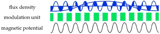
Figure 1.
Schematic diagram of the magnetic field modulation process.
In order to further quantitatively analyze the MFMM, the effect of the magnetic field modulation unit on the magnetic field needs to be expressed mathematically. Assuming that at the initial moment, the peak positions of the magnetic potential and magnetic flux are both at the origin position of the stator coordinate system, the equation for the no-load air gap flux density of the MFMM can be expressed as:
From the magnetic field expression, it can be seen that stable torque can only be generated when the number of harmonic poles of two magnetic fields and the rotational speed satisfy the following relationship:
For the sake of simplicity and intuitive expression of the principle of magnetic field modulation, Formula (1) only selects the fundamental waves of excitation electromotive force and air gap magnetic flux for derivation. In the formula, , , and represent the fundamental pole pairs of the excitation magnetic potential, air gap magnetic flux, and armature magnetic potential, respectively. i, j, and k are the harmonic orders corresponding to the excitation magnetic potential, air gap magnetic flux, and armature magnetic potential, respectively. and are the mechanical speeds of the excitation unit and modulation unit, respectively. is the mechanical speed of the harmonic of the magnetic electromotive force of the opposite pole armature for . is the electrical angular velocity of the harmonic of the armature magnetomotive force. is the excitation magnetic potential function, is the air gap magnetic permeability function, is the amplitude of the excitation magnetic potential function, is the constant term of the air gap magnetic permeability function, and is the fundamental amplitude of the air gap magnetic permeability function.
For MFMMs, they generally contain multiple excitation flux density harmonics that satisfy Equations (2) and (3), which means that this type of motor can use multiple excitation flux density harmonics with different pole pairs to participate in electromechanical energy conversion. In addition, the mechanical speed of each excitation flux density harmonic is often lower than the rotor mechanical speed, which introduces an additional deceleration amplification torque coefficient “pole ratio” in the average torque. Its physical meaning is the ratio of the number of pole pairs of the motor rotor to the number of pole pairs of the motor armature winding. It should be noted that in an MFMM, the rotor may not necessarily be the excitation unit, but also the modulation unit. Taking Figure 1 as an example, the excitation electromotive force of 11 pairs of poles was modulated by the modulation unit, and the harmonic of the working magnetic field was 1 pair of poles. As is well-known, at the same frequency, the larger the number of pole pairs, the lower the speed. Therefore, the pole ratio of this motor is 11.
3. Research on Motor Topology
3.1. Rotor Permanent Magnet Type (Permanent Magnet Vernier Motor)
PMVMs introduce modulation poles on the stator teeth of traditional permanent magnet synchronous motors (PMSMs) to modulate the magnetic field of the low pole number stator armature winding, thereby obtaining harmonic magnetic field components that can match and interact with the high pole number permanent magnet (PM) magnetic field. This can achieve low-speed high torque without increasing the motor volume and slot number.
The PMVM developed from a magnetic gear and belongs to the rotor excitation type of MFMM. The PM pole pairs, armature winding pole pairs, and the number of modulation teeth of a motor with this structure need to meet the following relationship:
In the formula, pr, kFMP, Z, and pw are the number of PM poles, modulation poles on the stator teeth, stator teeth, and armature winding poles, respectively. The corresponding harmonic rotation speed is:
Equation (5) shows that when the pole number of the air gap harmonic magnetic field is less than the pole number of the rotor PM, the sub harmonic rotation speed is higher than the rotor speed; on the contrary, when the pole number of the air gap harmonic magnetic field is greater than the pole number of the rotor PM, the sub harmonic rotation speed is lower than the rotor speed. For example, corresponds to the rational speed of in the polar harmonic magnetic fields. From here, it can also be seen that the number of rotor poles in PMVMs will be much greater than the number of stator teeth.
In recent years, the research team has proposed a focused magnetic PMVM (FMPMVM) structure [10], which uses tangential magnetization PM (spoke type) and the principle of magnetic pole repulsion to enhance the magnetic load and achieve high torque output. In addition, V-type and consequent pole arrangement also have a magnetic focusing effect [11,12,13]. However, the magnetic barrier effect in high pole ratio motors limits the effect of magnetic field modulation. For this, the authors of [14] proposed the continuous pole integrated rotor structure of an inverted T-type PM (Figure 2). The magnetization directions of the adjacent PM are the same, and the directions of the auxiliary PM at the bottom are the opposite, in order to avoid the closure of magnetic lines of force, ensure the stable output torque of the motor, and overcome the influence of the magnetic barrier effect. Reference [15] studied a type of PMVM with a magnetic barrier at the bottom of a V-shaped PM, and their results indicated that the introduction of a magnetic barrier could effectively regulate the original magnetic flux path, which is equivalent to generating a secondary modulation effect, thus increasing the effective magnetic flux circuit and improving the torque density.
Figure 2.
Topology structure of an inverted T-shaped motor [14].
From the structure of a magnetic circuit, the Halbach motor has a similar structure to a spoke motor, so the magnetic field is the same as the spoke type [16,17]. Compared with other rotor structures, the Halbach array exhibits better internal and external magnetic field strength. Wang proposed a novel Halbach PMVM (Figure 3). This structure inherited the advantage of the low torque ripple of the Halbach structure, but with an increase in PM dosage, the torque density increased by 40.8~69.01% on the basis of a 20% increase in dosage, and the torque ripple decreased by 11.74% [18].
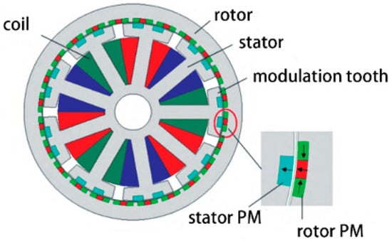
Figure 3.
New Halbach PMVM [16].
Reference [19] proposed a hybrid split tooth PMVM structure (Figure 4), which improved the optimization of the air gap magnetic field harmonics through a hybrid teeth design, increased the PF from 0.63 to 0.84, increased torque by 37%, and enhanced fault tolerance. The coding tooth structure was introduced in Reference [20] (Figure 5), which introduced specific harmonics through a special tooth profile to modulate multiple magnetic fields and induce in-phase counter potentials, effectively increasing torque and reducing pulsation. Reference [21] showed a variable pole PMVM (Figure 6), whose permanent magnet magnetic field was modulated by teeth to generate harmonics of different pole numbers and phasor diagrams, coupled with A and B type permanent magnet harmonics. By changing the number of armature poles, dual-mode operation was achieved, expanding the motor speed range by at least twice and improving the operational flexibility.
Figure 4.
Hybrid split tooth PMVM [19].
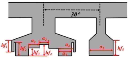
Figure 5.
Coding tooth structure [20].
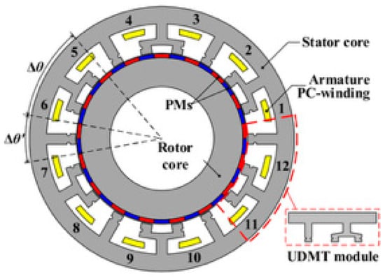
Figure 6.
The variable pole PMVM [21].
Reference [22] studied a non-uniformly arranged modulation pole PMVM, which is characterized by grouping modulation teeth with two or more teeth in each group. By adjusting the duty cycle of the modulating teeth or the relative position within the group, the reluctance can be reduced, the operating sub-harmonic amplitude can be increased, and the torque density can be enhanced to optimize the motor performance. The reference study showed that the torque performance of the non-uniform split tooth PMVM was slightly superior to the uniform tooth design, which benefits from the optimization of the motor slot vector [23]. Reference [24] proposed a novel hourglass shaped magnetic isolation structure for the primary and secondary tooth type PMVM (Figure 7), which could effectively adjust the air gap magnetic resistance and improve the harmonic characteristics. The hourglass shaped magnetic isolation bridge not only solved the problem of inter pole leakage, but also served to fix the PM.
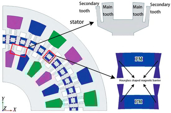
Figure 7.
Hourglass type PMVM [24].
In the PMVM, in order to achieve low speed and high torque, the number of rotor PM is usually more than the number of stator winding pole pairs, which leads to the increase in PM consumption with the increase in motor capacity. Therefore, a double-layer air gap structure (DLAG-PMVM) was proposed to improve the torque density. The Huazhong University of Science and Technology innovatively designed a consequent pole tangential excitation PMVM with connection bridge, which effectively enhanced the torque [25]. Dr. Zhang found that DLAG-PMVM was most suitable for MW level power generation and had the best torque performance. He proposed a rotor iron core with a bidirectional connection bridge structure (Figure 8) that completely eliminated the convex pole magnetic resistance introduced when the stator and rotor were slotted, making the amplitude of magnetic potential fluctuations between adjacent ferromagnetic poles equal and reducing magnetic potential fluctuations [26]. A double-stator PMVM without a rotor yoke was proposed in Reference [27]. Thanks to the increase in the inductance of the yoke structure, the high-speed operation was realized. Reference [28] proposed a dual stator, single winding axial PMVM. Compared with conventional axial motors, this motor reduced the axial length of the motor while ensuring constant torque, thereby improving the torque density. Reference [29] designed a new built-in saddle-type PM topology on the basis of double stators (Figure 9), with higher torque and lower vibration.
Figure 8.
Double connection bridge structure [26].
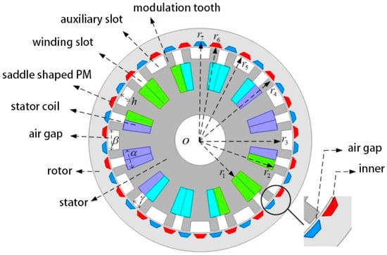
Figure 9.
Saddle PMVM [29].
In the fault tolerant design of a PMVM, the modular design of the stator and rotor is increasingly emerging [30]. Reference [31] described a high-tolerance linear PMVM (PMVLM). The motor adopted the best aligned PM array, six-phase winding, and modular mover design, which strengthened the thrust and reduced the phase coupling, and improved the fault tolerance and thrust performance. The motor could also operate under different phase conditions.
Superconducting permanent magnetic materials have been emerging in motor applications, and scholars are exploring superconducting PMVMs (SPMVMs) [32] with the aim to enhance the torque output by replacing PM or the nonconductive material in the modulation structure as the superconducting material. Reference [33] showed that when a high temperature superconducting material was applied to wind turbines and linear motors, the torque performance was improved, but the short circuit current was increased. At present, there are many studies on the application of high temperature superconducting materials for PMVLMs and DLAG-PMVMs [34,35,36].
In order to better quantitatively analyze the impact of the proposed new structure on PMVM performance, based on data analysis in the reference, this paper compared them with traditional PMVMs under the same volume through the following table, and the conclusions are as follows. The ‘-’ in the Table 1 represents a decrease.

Table 1.
Comparison of the PMVM performance among different structures.
In order to facilitate readers in selecting the appropriate PMVM architecture based on the application scenario, this article summarizes the corresponding relationship and recommended solutions between typical application scenarios and PMVM performance structures in Table 2.
Table 2.
Relationship between PMVM structure performance characteristics and typical application scenarios.
The development of PMVMs has always faced a profound contradiction between performance breakthroughs and engineering practicality. This special motor, which achieves low-speed high torque through harmonic coupling, has to bear multiple design costs while pursuing a high power density.
The core contradiction is reflected in the Halbach array, spoke type, and other magnetic gathering structures used to improve the torque density, which can achieve improved torque performance but require PM incremental costs; the carefully designed hybrid split tooth structure can optimize motor harmonics, but at the cost of complex manufacturing processes. Innovative topologies such as the dual stator and double-layer air gap significantly increase the assembly accuracy requirements and manufacturing costs while improving the torque output. More importantly, these structural innovations often constrain each other—designs that reduce the torque ripple may sacrifice power density, while solutions that improve reliability may affect the efficiency.
This design dilemma essentially stems from the physical limitations of the PMVM: the principle of magnetic field modulation dictates a positive correlation between its torque performance and vibration noise, so an increase in PM usage inevitably drives up costs, and the simplification of topology may weaken its core advantages. There is a tendency in current research to excessively pursue the optimization of individual indicators while neglecting the balance of cost-effectiveness in systems engineering. The introduction of new technologies such as superconducting materials may seem promising, but their feasibility for industrialization remains questionable.
The future of PMVMs does not lie in endless structural complexity, but should shift toward: (1) establishing a precise “performance cost” quantitative evaluation system; (2) developing a compromise design solution that balances electromagnetic performance and manufacturability; and (3) exploring new control strategies to overcome hardware limitations. Only by facing these design trade-offs can PMVMs truly move from the laboratory to industrialization.
3.2. Stator Permanent Magnet Type
3.2.1. Switched Flux Linkage Permanent Magnet Motor
As a kind of stator permanent magnet motor, the switched flux linkage permanent magnet motor (SFPM) has the outstanding advantages of high torque density, simple rotor structure, strong anti-demagnetization ability, etc., and has gradually become a research hotspot in the motor industry. Related products have been successfully applied to transportation, intelligent manufacturing, industrial control, and other fields [37].
The PM of SFPM is a tangential excitation structure, which is placed in the middle of the stator teeth and runs through the whole stator core. The polarity of two adjacent PMs is the opposite. Both the stator and the rotor are laminated by silicon steel sheets. The rotor is a simple reluctance structure. The stator winding is mostly a centralized winding structure, and there is also a distributed winding structure. The magnetic line of the force distribution of the SFPM is shown in Figure 10. Because the polarity of two adjacent PMs is the opposite, the magnetic line of force is squeezed into the stator teeth, passes through the adjacent rotor teeth with the winding turn chain, and returns from the other stator teeth to form a closed loop. Furthermore, as the relative position of the rotor teeth and PM changes, the direction of the flux linkage through the winding also changes, where the winding flux linkage reaches the maximum in the positive direction (Figure 10a) and the winding flux linkage reaches the maximum in the negative direction (Figure 10b), therefore, the winding flux linkage of the SFPM is bipolar, which can produce high back potential and torque.
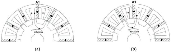
Figure 10.
Magnetic force line distribution at different locations of the SFPM rotor. (a) Winding flux linkage forward maximum. (b) Winding flux linkage negative maximum.
The SFPM is mainly divided into the V type and E type, of which the V type is mature and common; the E type adds intermediate teeth to each stator tooth for thermal isolation and reduced heat effects. Figure 11 and Figure 12 show these two configurations, and the reference comparison shows that the E type has better torque performance. A series of improved topologies have been developed based on this [38].
Figure 11.
E type SFPM.
Figure 12.
V type SFPM.
Reference [39] explored the reluctance torque and pulsation causes of SFPM, pointing out that the reluctance torque is invalid under the control of id = 0, and put forward the torque suppression pulsation by stator and rotor chamfering method. Reference [40] designed a new structure of a cosine-reduced rotor based on the air gap magnetic field modulation theory to effectively suppress torque ripple. Reference [41] proposed that the partitioned stator multi-excited SFPM (Figure 13) is provided with an auxiliary excitation winding in the stator to enhance the flux-weakening capability. Reference [42] showed a tubular linear SFPM with no end winding where the efficiency was high and the net radial force was zero (Figure 14). Axial SFPM outperformed radial SFPM in terms of length and torque density. The axial SFPM for the yoke less dual rotor presented in [43] used segmented armatures with a higher torque density and lower slot torque.
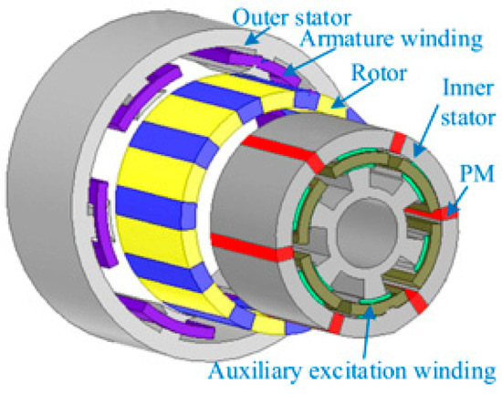
Figure 13.
The partitioned stator multi-excited SFPM [41].
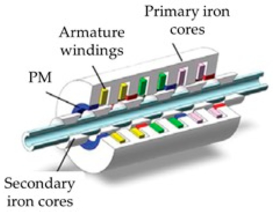
Figure 14.
The tubular linear SFPM [42].
The switched flux linkage linear motor (SFLM) often improves the thrust density by means of a primary modular design [44]. However, the air gap magnetic flux of SFLPM is difficult to adjust due to PM excitation, and it is difficult to meet the wide speed constant power operation, which limits the wide speed change application [45]. References [46,47,48] further studied the bilateral magnetic circuit complementary modular electrical excitation SFLM (ESFLM) and optimized the design parameters globally. Reference [49] conducted a comparative analysis of the ESFLM for convex pole and segmented rotor structures, and found that the power and torque of segmented rotor structures were 3.1 times and 2.1 times higher than those of convex pole structures, respectively. Reference [50] suggested that the two-side ESFLM of non-overlapping winding had a higher thrust density, higher efficiency, and better heat dissipation. The innovative set in Reference [51] overlapped the armature winding with the asymmetric stator pole over the ESFLM, reducing the magnetic saturation and improving the torque density. Reference [52] suggested that an octane modular stator structure improved the torque density of the ESFLM. Reference [53] proposed an HTS modular SFLM. The motor adopted a low-cost salient pole iron core stator, short moving sub-armature, and HTS excitation winding with low torque pulsation and strong fault tolerance. Reference [54] proposed a method of improving the phase-locked loop by combining a primary dislocation bilateral SFLPM with a second-order notch filter to improve the accuracy of position and velocity estimation. Reference [55] suggested that the secondary core transverse flux SFLPM (Figure 15), unlike conventional linear motors, produces thrust in each phase of the structure with an independent magnetic circuit.
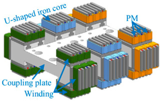
Figure 15.
Transverse flux SFLPM [55].
The quantitative analysis of the relevant literature is shown in Table 3.
Table 3.
Comparison of the SFPM performance among different structures.
This article summarizes the corresponding relationship and recommended solutions between typical application scenarios and SFPM performance structures in Table 4.
Table 4.
Relationship between SFPM structure performance characteristics and typical application scenarios.
SFPM combines the advantages of high power density and robustness through the fusion of stator permanent magnets and doubly salient structures. Its design with both permanent magnets and windings placed in the stator improves heat dissipation and ensures that the rotor is suitable for high-speed operation, making it particularly suitable for high-performance applications such as aerospace servos. However, the main contradiction between torque performance optimization and vibration suppression lies in the fact that although the fixed rotor taper method and cosine taper structure can effectively suppress torque pulsation, such geometric optimization often comes at the cost of sacrificing some output capability. The multi-excitation design of partitioned stator improves the weak magnetic performance by adding auxiliary windings but inevitably increases the system complexity and manufacturing costs. The advantage of axial topology over radial structure in torque density is accompanied by new challenges in mechanical strength and heat dissipation. Although the modular design significantly improves the thrust density, the difficulty in adjusting the air gap magnetic field due to the permanent magnet excitation characteristics severely restricts the ability to operate in a wide speed range. The electric excitation scheme achieves torque multiplication through innovative structures such as segmented rotors, but its non-overlapping winding and special pole design significantly increase the complexity of the manufacturing process. It is worth noting that the second-order notch filter and other strategies used to improve control accuracy essentially trade algorithm complexity for performance improvement, and this compensation at the control level in turn puts higher demands on processor performance.
3.2.2. Flux Reversal Permanent Machine
The basic topology of a flux reversal permanent machine (FRPM) is shown in Figure 16, and two pieces of PM with opposite magnetizing directions are mounted on the surface of each stator tooth facing the air gap side. FRPM can be subdivided into two structures according to the magnetizing modes of the two adjacent PM: in magnetizing mode 1, defined in Figure 16a, the PM magnetizing directions on both sides of the stator slot are the opposite; in magnetizing mode 2, defined in Figure 16b, the PM magnetizing directions on both sides of the stator slot are the same. Figure 17 shows the working principle of the FRPM under the two magnetizing modes, that is, at the initial position, the magnetic flux of each pole provided by the PM enters the coil along the air gap. When the rotor turns a certain angle, the permanent magnetic flux is just reversed, so the magnetic flux leaves the coil and enters the rotor along the air gap. It can be seen that regardless of the kind of magnetizing mode, when the rotor rotates, it will cause a permanent magnetic flux change on the turn chain in the coil, generating a no-load induced electromotive force [8]. Reference [56] comprehensively compared the influence of different magnetizing modes and PM quantity on the electromagnetic torque of an FRPM. The research showed that the arrangement of NSNS-SNSN could obtain a larger electromagnetic torque.
Figure 16.
FRPM basic structure: (a) magnetizing mode 1; (b) magnetizing mode 2.
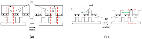
Figure 17.
Working principle of the FRPM under different magnetizing modes: (a) magnetizing mode 1; (b) magnetizing mode 2.
Reference [57] proposed a new type of FRPM, with a PM affixed on the stator teeth, which effectively counteracts invalid harmonics through a special winding design and current sequence. Reference [58] compared symmetric and asymmetric rotor structures and confirmed that asymmetric rotors can flexibly adjust the air gap magnetic permeability function, optimize the harmonic characteristics, and significantly reduce the torque ripple. References [59,60] designed an I-type stator transverse flux reverse permanent magnet linear motor (FRLPM) (Figure 18) that adopted a transverse magnetic circuit structure to achieve the complete decoupling of electrical and magnetic loads. Reference [61] used the grey relational Taguchi method to optimize the variable tooth width FRPM vibrating mirror motor to improve the torque density and dynamic performance. An asymmetric stator pole FRPM was proposed in Reference [62] to solve the problem of flux leakage between adjacent PM poles. Reference [63] adopted a double stator FRPM with the same inner and outer stator structures. The topology can be regarded as a simple superposition of two FRPMs, and the torque density was improved. Reference [64] investigated the double-sided unstopped asymmetric FRPLM (Figure 19), which is suitable for long distance applications with a high thrust density. In Reference [65], an axially stacked polyphase FRPM (Figure 20) was proposed, which was based on the multilayer design method. Each layer was a single-phase FRPM, and each layer had a mechanical angle of 120°. This structure effectively reduced the torque ripple. In Reference [66], a reverse-flux claw pole motor with soft magnetic composite magnetic core was proposed based on the advantages of the claw pole motor and FRPM, and a higher torque coefficient was found in the research. Reference [67] proposed a new partitioned stator FRPM (Figure 21) that was equivalent to the combination of two groups of FRPM, and the two groups of PM were respectively placed in the stator teeth and the rotor slot, reducing the risk of electric excitation pressure and stator saturation. Reference [68] proposed a synthetic slot type FRPM, which combined radial and tangential PM and had excellent torque performance. Reference [69] proposed an axial field double-rotor FRPM (AF-DR FRPM) for use in a magnetic differential system (Figure 22) that decoupled the magnetic flux between two rotors by means of a surface-mounted PM, so that the two rotors could rotate independently. Reference [70] introduced a new dual rotor FRPM topology with a hollow stator, high-temperature superconducting excitation coil, and superconducting magnetic shielding structure. References [71,72] optimized the design of the transverse pole stator, greatly reducing the PM eddy current loss and improving the motor efficiency. Reference [73] proposed that the “Fe/N-Fe/N-Fe/Fe/Fe” asymmetric stator alternate pole FRPM had better counter electromotive force and torque density than traditional alternate pole FRPMs and asymmetric stator FRPMs.
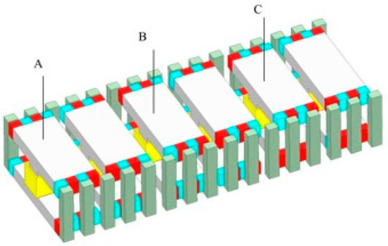
Figure 18.
I-type stator transverse FRPLM [59].
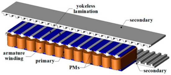
Figure 19.
The double-sided unstopped asymmetric FRPLM [64].
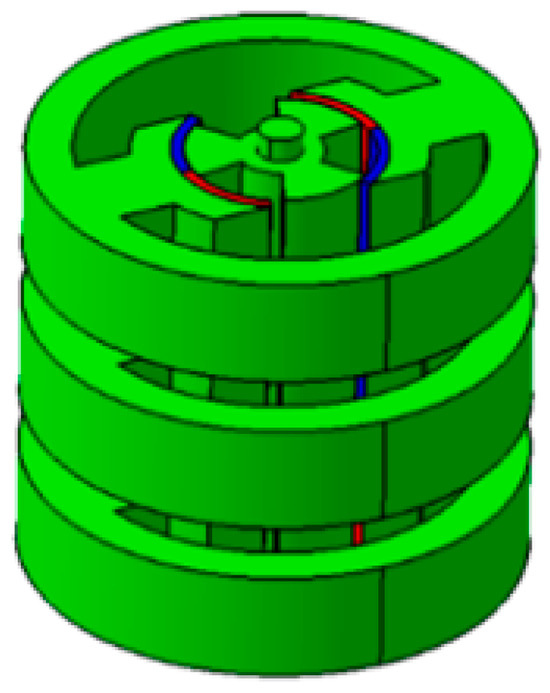
Figure 20.
The axially stacked polyphase FRPM [65].
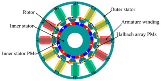
Figure 21.
PS-FRPMM [67].
Figure 22.
AF-DR-FRPM [69].
In order to enhance the torque capacity of the motor, the excitation winding is sometimes added to the FRPM to form a hybrid excitation motor, but the simultaneous presence of the armature and the excitation winding in the stator will cause interference in their spatial positions. For this reason, zero-sequence current technology has been proposed to solve this problem [74,75], which integrates excitation and armature winding. Thanks to zero-sequence current technology, the stator MFMM offers improved flux control and torque.
The quantitative analysis of the relevant literature is shown in Table 5.
Table 5.
Comparison of FRPM performance among different structures.
This article summarizes the corresponding relationship and recommended solutions between typical application scenarios and FRPM performance structures in Table 6.
Table 6.
Relationship between FRPM structure performance characteristics and typical application scenarios.
The FRPM is a stator permanent magnet doubly salient motor that drives the rotor by reversing the direction of the magnetic field through periodic switching of the stator tooth magnetic poles. Its main advantage is that the rotor structure is extremely simple and sturdy, and does not require permanent magnets, making it particularly suitable for high-speed operation and harsh environments. The stator PM has excellent heat dissipation conditions, and when combined with centralized windings, it can increase the power density. By optimizing the slot matching, the torque ripple can be effectively suppressed.
However, in terms of torque optimization, although asymmetric rotor structures and stator pole designs can effectively reduce the torque ripple and leakage problems, they often come with an increase in manufacturing process complexity. Although the special winding design and current timing control can offset ineffective harmonics, they pose higher requirements for control algorithms. Innovative topologies such as multilayer design and partitioned stator enhance torque density through spatial combinations (such as axial stacking and dual rotor structures), but this performance gain comes at the cost of sacrificing structural compactness and increasing assembly difficulty.
Although the introduction of excitation windings in the hybrid excitation scheme can enhance the torque regulation capability, the spatial competition between the armature and excitation windings leads to a more complex magnetic circuit design. Although zero-sequence current technology alleviates this contradiction through winding integration, it may affect the efficiency of current utilization. It is worth noting that non-traditional structures such as the transverse magnetic flux and axial magnetic field not only increase the thrust density, but also make magnetic circuit analysis and optimization more difficult.
3.3. Double Permanent Magnet Type
In order to further improve the torque density, a kind of double permanent magnet field modulation motor (DPMFMM) with PMs placed at the stator and rotor side at the same time is proposed. Such a motor can effectively improve the torque output capacity of the motor by relying on the “bidirectional field modulation effect” [76]. Its typical structure is shown in Figure 23.
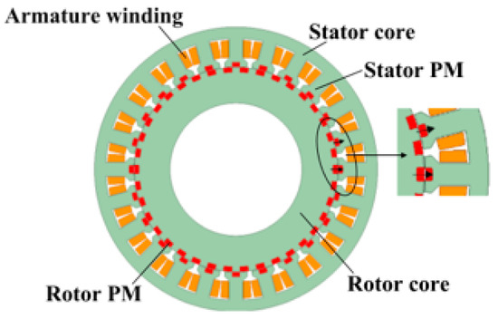
Figure 23.
DPMFMM [76].
Reference [77] proposed a DPMFMM with a “U” type PM embedded in the stator teeth and studied its torque generation mechanism. Reference [78] proposed a dual PM MFMM with a “T” shaped PM rotor and demonstrated an 8% improvement in torque density over conventional motors. Reference [79] proposed an N/S PM offset structure to reduce the cogging torque of DPMFMM. References [80,81] proposed the structure of a double PM flux reversal motor (Figure 24) and analyzed the working principle of the motor from the field modulation and flux linkage change, where the results showed that the motor had higher torque density and PF than the traditional FRPM and PMVM. Reference [82] proposed a hybrid excitation DPMFMM using the DC bias sinusoidal current. The motor realizes flux regulation by using a DC component in the current, which can combine high torque density with good field regulation capacity. References [83,84] introduced the concept of double PM into the design of the transverse flux motor, proposed transverse flux rotation DPMFMM, and linear DPMFMM, respectively, and proved that the performance of both types of motors was improved. Reference [85] proposed a mixed PM double stator DPMFMM (Figure 25) with ferrite and Nd-Fe-B placed at the outer stator slot and rotor, respectively, introducing a “bidirectional field modulation effect” by using a double alternating pole PM arrangement.
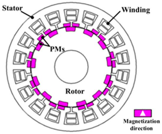
Figure 24.
The double PM flux reversal motor [80,81].
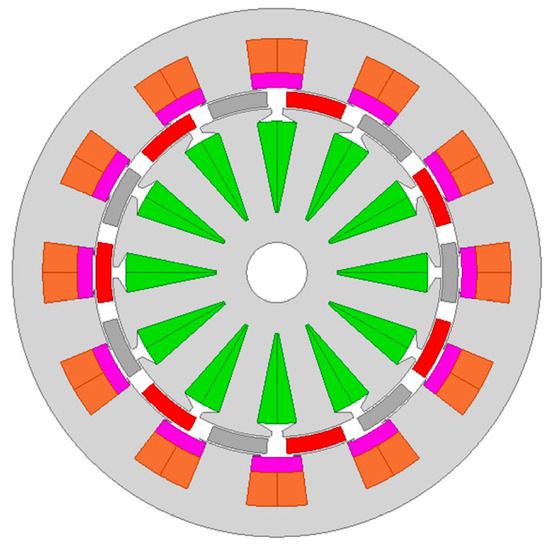
Figure 25.
The mixed PM double stator DPMFMM [85].
Compared with the single excitation MFMM, the quantitative comparison of the relevant performance in the above reference is shown in Table 7.
Table 7.
Comparison of the DPMFMM performance among different structures.
This article summarizes the corresponding relationship and recommended solutions between typical application scenarios and DPMFMM performance structures in Table 8.
Table 8.
Relationship between DPMFMM structure performance characteristics and typical application scenarios.
The bilateral excitation MFMM significantly improves torque density and magnetic field control flexibility through stator rotor cooperative excitation, demonstrating potential in high demand fields such as aerospace. However, its complex dual excitation structure leads to increased manufacturing costs, doubled control difficulty, and inherent contradictions between copper and iron consumption in efficiency optimization. Despite its superior theoretical performance, it is still necessary to be cautious of the risk of “over design” in practical applications—if topology innovation (such as hybrid excitation integration) or intelligent control cannot break through the constraints of cost and complexity, such motors may be trapped in the laboratory stage, and optimizing the cost-effectiveness of single-sided excitation schemes is more practical in engineering.
4. Motor Characteristics Study
4.1. Torque Capacity
MFMMs operate based on the field modulation principle. Due to the flexible design of the modulation pole, excitation pole, winding, etc., a “self-increasing” effect can be realized by selecting the proper low pole logarithm operating sub-harmonics and utilizing the field modulation effect. Without increasing the number of pole slots of the motor, the torque density of the motor is improved, which has attracted extensive attention in the field of low speed and large torque. With the development of various industrial fields, the requirements for space intensification and system lightweight have increased sharply, so the requirements for motor structure and torque density are higher.
4.1.1. Torque Density Improvement
The air gap magnetic field of a field-modulated motor contains abundant harmonics, and its utilization rate for harmonics is higher than that of a common PMSM with a higher torque density. Therefore, the design of an MFMM harmonic magnetic field has become one of the magic weapons to improve the torque density of the motor.
Harmonic Optimization
Reference [86] analyzed the air gap permeability function in depth and pointed out that the harmonic component was mainly generated by the permeability change caused by the slotting of the stator and rotor, which lays a theoretical foundation for optimizing the motor performance from the harmonic angle. Reference [87], using Maxwell’s stress tensor method, defined the contribution of dominant operating harmonics to the dominant PMVM torque and explained its high torque density mechanism. Reference [88] discussed the winding phase shift technology of PMVMs and found that an appropriate phase shift angle could not only eliminate the non-operating sub-magnetomotive force harmonics, but also enhance the operating sub-harmonic winding factor, thus improving the torque density. Reference [89] systematically summarized the air gap harmonic characteristics of the MFMM under different excitation sources. Reference [90] proposed a multiharmonic layering method, which realized the accurate layering of harmonic contribution based on the relationship between the optimization target and air gap harmonic. The results showed that the optimization of the target harmonic of each layer significantly improved the motor performance. In Reference [91], the energy method was used to calculate the harmonic contribution and accurately characterize the harmonic counter-electrical potential and harmonic torque. Reference [92] innovatively proposed improving the torque by air gap magnetic field compensation. This method introduces a harmonic factor and torque compensation factor, which effectively reflect the torque compensation effect.
Control Strategies
Many researchers have used advanced algorithms and control technologies to further optimize the motor torque performance and calculation accuracy. Reference [93] successfully improved the output torque of internal, external, and double-stator PMVMs and effectively reduced the torque ripple by using the nondominant sorting genetic algorithm. In Reference [94], an automatic nonlinear equivalent magnetic circuit modeling method was proposed to optimize the ESFPM design and maximize the torque output by parametrizing the motor split ratio and stator core yoke height. Reference [95] constructed a mixed analysis model, combined with the sub-domain model and the conformal transformation, which accurately considered the stator and rotor slotting effect, and found that the rotor slotting had a more significant impact on the air gap magnetic field.
In recent years, the maximum torque per ampere (MTPA) has been widely used in brushless double-fed motors (BDFMs) [96,97]. References [98,99] studied the maximum torque per total ampere (MTPTA) control strategy of the BDFM drive, which considered the iron loss and used the mathematical curve to determine the minimum total current amplitude approximately, with fast response and high accuracy. Reference [100] improved the FRPM torque by using the third harmonic injection method, while Reference [101] proposed the ESFPM vector control mechanism based on PWM technology to maximize the torque by controlling the stator field direction. Meanwhile, MFMM has significant potential in high-frequency performance compared with PMSM. Its magnetic field modulation mechanism can effectively suppress PWM harmonics, reduce the voltage ripple, and minimize electromagnetic interference by optimizing the magnetic circuit design. However, this advantage highly relies on precise modulation algorithms and magnetic circuit optimization. If not controlled properly, it may lead to increased iron loss or the introduction of new high-frequency harmonics due to multiple magnetic circuit structures.
The quantitative description of torque density enhancement using optimization methods in the relevant literature is shown in Table 9. The typical application scenarios of each literature are shown in Table 10.
Table 9.
Comparison of different optimization methods for torque density enhancement.
Table 10.
Comparison of torque density enhancement strategies and recommended application scenarios.
4.1.2. Torque Ripple Reduction
The MFMM has the advantages of low-speed high-torque operation, direct drive, etc., and the main objective of this kind of motor optimization is to reduce the torque ripple while ensuring the torque density. In recent years, there has been a number of references on the generation mechanism, motor structure, and control models to reduce the torque ripple of MFMMs.
Harmonic Optimization
For the generation mechanism of the MFMM torque ripple, Reference [102] defined the coupling harmonic group factor starting from the analysis and research on the modulation principle considering magnetic coupling, and its novelty lies in the concept of the positive coupling harmonic and negative coupling harmonic. Reference [103] explained the influence of motor modulation teeth on the air gap magnetic density waveform and harmonic distribution based on the modulation process of a PM magnetic field and armature reaction magnetic field, and analyzed the change rule of air gap harmonic distribution with the opening angle of the stator slot on this basis to provide design guidance for reducing the cogging torque. Reference [104] showed that negative-contribution harmonics were the main source of torque ripple, and the torque ripple of the motor could be effectively reduced by optimizing these harmonics.
Control Strategies
From the perspective of control strategy, a system-level robust design optimization method was proposed in Reference [105], which effectively reduced the torque ripple of the driving system of the switched reluctance motor and improved the comprehensive performance. Reference [106] improved the torque tracking accuracy at a low modulation ratio by improving the accurate dead band predictive flux linkage control. Reference [107] combined sensitivity analysis, adopting multi-objective orthogonal optimization and particle swarm optimization, proposed the orthogonal particle swarm optimization algorithm, solved the optimization accuracy and computational quantity problems, and significantly improved the motor performance.
The comparison of different optimization methods for reducing the torque ripple in MFMMs is shown in Table 11. The typical application scenarios of each literature are shown in Table 12.
Table 11.
Comparison of different optimization methods for reducing torque ripple in MFMMs.
Table 12.
Comparison of torque ripple reduction strategies and recommended application scenarios.
Through a systematic analysis of the existing literature, it can be concluded that current optimization research on the torque characteristics of MFMMs mainly focuses on two key directions: firstly, improving the magnetic field harmonic characteristics by optimizing the motor body design (such as pole slot matching, magnetic barrier structure, etc.), thereby enhancing torque output performance; and secondly, developing advanced control strategies (such as harmonic current injection, direct torque control, etc.) based on modern control theory to fully unleash the potential of the motor. Future research can continue to deepen the exploration of these two directions, while paying attention to the collaborative optimization between them, in order to further improve the torque performance of magnetic flux modulation motors.
4.2. Power Factor
The low PF problem of MFMMs has plagued their popularity because it needs to be matched with a converter with a higher power capacity in practical application. Therefore, in recent years, improving the PF of MFMMs has become a research hotspot. Although the high torque density characteristics of MFMMs have been proven, a low PF remains an inherent disadvantage of this type of motor due to the serious leakage of the motor itself [108].
4.2.1. Air Gap Magnetic Flux
The low effective flux density of the air gap excited by the PM is often the main reason for a low PF. Changes in the PM topology affect the air gap flux and hence the PF, indicating that some PM designs can improve the PF of the MFMM. This is because the machine’s magnetomotive force and permeability are critical to the air gap flux density [109,110]. The magnetomotive force harmonics have a profound influence on MFMMs. Reference [111] proposed the method of the synergetic optimization of PMs and armature air gap harmonics, and defined the relationship between harmonic order and PF and torque. Reference [112] optimized the load air gap harmonic with a linear weighting method to improve the PMVM PF. Reference [113] compared and analyzed the influence of the magnetic source topology effect on PF and found that the PF of the surface embedded PM structure was better. Reference [19] studied the PF of the fault tolerant MFMM and proposed a design strategy to improve torque and PF through the magnetic field coupling analysis. Reference [114] pointed out that it is difficult to improve the MFMM PF by adjusting the PM parameters, and the slot leakage inductance had a greater impact. Reference [115] put forward a modeling method based on conformal mapping, which could accurately calculate the motor magnetic load, consider magnetic leakage, analyze the influence of the slot effect on the air gap magnetic density and armature winding function, and obtain an accurate calculation formula of the torque and PF.
4.2.2. Winding Inductance
In addition, the winding has an impact on the motor’s PF, mainly acting through the winding inductance. Reference [116] pointed out that the PF of a double stator MFMM is affected by the inductance of inner and outer windings. When the inductance of a single coil is close to or equal to each other, the maximum PF can be obtained when the number of turns is equal; on the contrary, it is optimal when the number of turns is different. Reference [117] re-modeled the relationship between the armature and PM harmonics and their relationship with the inductance and counter electromotive force, and identified the key factors affecting the power factor. Reference [118] calculated each inductance component, extracted the intrinsic coefficient of PF, and guided the initial design. Reference [119] adopted the hierarchical optimization to deduce and optimize the PM flux linkage and synchronous inductance layer, respectively, to improve the PF of the motor.
The comparison of the improvement in the MFMM power factor by different optimization methods is shown in Table 13. The typical application scenarios of each literature are shown in Table 14.
Table 13.
Comparison of different optimization methods for improving the power factor of MFMMs.
Table 14.
Comparison of power factor strategies and recommended application scenarios.
The low power factor problem of the MFMM has become the main bottleneck restricting its engineering application, which is essentially due to its special electromagnetic mechanism. From the perspective of electromagnetic design, this type of motor has two inherent characteristics: first, the effective air gap magnetic density generated by permanent magnet excitation is relatively low, and there is a significant leakage effect in the magnetic circuit; the second issue is the insufficient matching between the inductance parameters of the winding and the magnetic circuit structure, resulting in an excessive proportion of reactive power. In response to these issues, the current research mainly seeks breakthroughs from three dimensions: in terms of magnetic circuit optimization, improving the PM topology structure and modulation pole design to enhance the air gap magnetic density; in terms of harmonic management, harmonic suppression and utilization techniques are used to improve the quality of magnetic field waveforms; and in terms of the winding design, reactive power losses are reduced by optimizing the inductance parameters and winding configuration. Although these technological paths have achieved certain results, the improvement in the power factor still faces dual challenges in theory and technology due to the unique working principle of the MFMM. The future breakthrough direction should focus on the collaborative optimization of electromagnetic thermal mechanical multiphysics fields and systematically solve this key technical problem by combining new magnetic materials and intelligent control strategies.
4.3. MFMM Characteristic Analytical Method
In the torque harmonic analysis of MFMMs, commonly used modeling methods mainly include the energy method and Maxwell tensor method. Reference [120] classified the contribution of the air gap magnetic field harmonic torque of a flux concentration MFMM using the Maxwell tensor method and verified the applicability of this method in magnetic field modulation motors. Research has shown that the 14th, 32nd, and 42nd harmonics generate forward driving torque, while the 4th harmonic manifests as braking torque, and the 30th harmonic dominates torque ripple. Reference [121] verified the motor torque using Maxwell’s tensor method, but there is a theoretical contradiction in this method: during motor operation, there is no relative motion between the permanent magnet on the stator side and the winding, so the stator permanent magnet itself does not generate back electromotive force. However, the calculation results of Maxwell’s tensor method showed that it contributed to the effective torque. In contrast, the energy method had more systematic advantages in magnetic field harmonic analysis, and is especially suitable for optimizing the performance of magnetic field modulation motors with unilateral excitation. For example, Reference [20] used the energy method to verify the encoded tooth shaped magnetic field modulation motor, successfully achieving torque enhancement and torque ripple suppression. Reference [122] analyzed the phase relationship between the working harmonics of the winding magnetomotive force and the permanent magnet magnetomotive force using the energy method and directionally derived the optimized parameters of the stator magnetic flux, significantly improving the power factor of the motor. In addition, Reference [123] established a quantitative method for the contribution of harmonics to back electromotive force and torque based on the energy method. By identifying the harmonic orders with negative contributions in differential modulation motors, innovative reuse of these harmonics was achieved. It is worth noting that DPMFMM introduces ineffective harmonics while increasing the effective operating harmonics [124]. In response to this issue, Reference [125] proposed a DPMFMM air gap harmonic contribution analysis method, which confirmed that some air gap harmonics can have a negative impact on the back electromotive force and torque. Research has shown that guided by the energy method, by suppressing or converting these negative contribution harmonics, the torque density of the motor can be effectively improved. Reference [91] was based on a new DPMFMM structure optimized by the energy method. By adjusting the position of the permanent magnet and modulating the tooth parameters, the reuse of negative contribution harmonics was achieved, and the torque density was increased by 60%. The accuracy of the energy method in analyzing complex modulation relationships was experimentally verified.
5. Development Trend and Application Prospect of MFMM
The concept of the MFMM subverts the traditional motor theory, breaks the restriction that excitation and armature pole pairs are equal, and expands the motor structure evolution. The MFMM makes full use of the magnetomotive force harmonics to significantly improve the motor output torque and has a variety of topologies that can be flexibly applied to different fields. Compared with traditional motors, the MFMM torque is greatly improved, showing wide application prospects in the new energy power generation, electric vehicles, ship propulsion, and military fields, and opening up a new space for motor performance improvement. In the field of new energy generation, the MFMM is particularly suitable for direct drive wind turbines. Its high torque characteristics can effectively cope with low wind speed conditions, and the modulated magnetic field design can adapt to a wide speed range of operations, significantly improving the power generation efficiency. In terms of electric vehicle applications, the high power density characteristics of the MFMM can reduce the motor volume and weight, providing greater flexibility for vehicle layout. Its excellent low-speed high torque performance is particularly suitable for heavy-duty commercial vehicles and off-road vehicles. In ship propulsion systems, MFMMs achieve torque amplification through magnetic field modulation, which can replace some gear transmission devices and improve the reliability and energy efficiency of the propulsion system. In the field of military equipment, MFMMs perform well in scenarios such as electric armored vehicles and shipborne electromagnetic catapult systems as their fast dynamic response and anti-demagnetization capabilities meet the requirements of harsh combat environments. In addition, MFMM’s advantages of high-precision torque control and compact structure are creating new application possibilities in high-end equipment fields such as industrial robot joint drives, aerospace actuation systems, and oil drilling and production equipment. However, at present, MFMMs still have the following problems that need to be solved:
- (1)
- Excessive torque ripple. MFMMs have a stronger ability to utilize field harmonics than ordinary motors, but we should not ignore the fact that the motor is completed on the basis of increasing all sub-harmonics. How to improve the effective working sub-harmonics and reduce non-working sub-harmonics will always be the focus of research on MFMMs. In terms of motor structure, in the future, the sinusoidal nature of the air gap magnetic field can be optimized, and harmonic torque can be reduced by improving the magnetic barrier structure of the rotor/stator (such as layered magnetic barriers, asymmetric magnetic pole design) or adopting a multipole logarithmic combination. Alternatively, a hybrid excitation structure can be used to dynamically adjust the magnetic field strength to suppress torque pulsation. Advanced motor control strategies can also be adopted, such as the harmonic current injection method and intelligent algorithms, that apply deep reinforcement learning to optimize the current waveform and switching frequency in real-time and adaptively suppress pulsation.
- (2)
- Complicated motor structure. The introduction of the “field modulation” principle has already increased the complexity of the MFMM structure compared with conventional machines. In recent years, MFMM structural models of more and more complex structures have been proposed in order to improve the motor performance. Although these motors have excellent performance, their structure is extremely complex, and their processing and maintenance are extremely difficult, which is not conducive to large-scale popularization and application. In the future, modular design and symmetry optimization may be adopted to solve motor design problems. For example, using standardized functional modules (such as interchangeable magnetic pole units and integrated windings) can reduce the assembly complexity while maintaining modulation performance. the magnetic field modulation structure can be simplified through symmetrical magnetic circuits or quasi uniform air gap design while meeting the torque requirements. In the field of motor manufacturing, 3D printing can be used to achieve complex topologies that are difficult to process with traditional techniques, while reducing the number of parts.
- (3)
- The PF is generally low, particularly in high pole ratio designs. Although the torque output is large, most of the energy is consumed by reactive power, limiting its application in the high-precision field. In the future, dynamic adjustable electromagnetic modulation units, such as auxiliary excitation windings, can be introduced to optimize the air gap magnetic field distribution in real-time and reduce reactive current demand. Alternatively, a bidirectional magnetic field modulation structure of the rotor/stator can be used to offset the inductive reactive power component through phase compensation. At the same time, advanced intelligent control strategies can be adopted to detect the harmonic reactive power in real-time, inject high-frequency currents of specific phases (similar to active filtering), and offset the reactive power components of low-order harmonics. In terms of material innovation, gradient magnetic materials and programmable magnetic materials can be used to achieve a natural sinusoidal magnetic field and reduce the reactive magnetization current.
- (4)
- Large loss. Limited by material performance, hysteresis and eddy current loss are difficult to break through, resulting in low energy efficiency and high operation costs, which limits its application in the high-precision and high-efficiency fields. Therefore, reducing loss and improving efficiency has become a key issue in the field of MFMMs. Whether this problem can be solved will directly affect the development prospect and market potential of MFMMs. In the future, various composite materials, such as nanocrystalline soft magnetic alloys and amorphous alloy graphene composite magnetic cores, can be utilized to achieve the self-suppression of eddy current losses and block eddy current paths under high-frequency magnetic fields. In terms of winding technology, superconducting materials can be used in key areas to achieve zero resistance electrification.
- (5)
- Fault diagnosis faces new challenges. The unique magnetic field modulation mechanism of MFMMs has resulted in significant differences in its fault characteristics compared with traditional motors, mainly manifested in three aspects. Firstly, the failure of the modulation unit (such as modulation pole deformation or demagnetization) will generate special harmonic characteristics, requiring the development of dedicated modulation harmonic analysis algorithms. Secondly, the coupling effect of multiple physical fields makes it difficult for single sensor data to accurately reflect the nature of the fault. Therefore, multisource information fusion technology is needed such as combining high frequency current signals, vibration spectra, and infrared thermography for comprehensive diagnosis. Thirdly, the dynamic modulation process leads to time varying fault characteristics, and traditional threshold detection methods are prone to misjudgment. The latest solution includes building a deep learning based digital twin model to achieve early fault warning by comparing the difference in magnetic field distribution between the measured data and health benchmarks, developing adaptive resonance demodulation technology to effectively extract the characteristic frequencies of mechanical damage in modulation units; and applying transfer learning algorithms to solve the problem of fault feature drift under different operating conditions. These innovative methods provide new ideas for the intelligent operation and maintenance of MFMMs.
6. Conclusions
Based on the basic operating principle of MFMMs and the location of the excitation unit, this paper summarized the topological studies of PMVMs, SFPMs, FRPMs, and DPMFMMs in recent years. Subsequently, the relatively valuable references to MFMMs in recent years were analyzed from the urgently needed characterization problems. In general, MFMMs have made great progress in basic theory, topology structure, and performance optimization, and have been widely used in many fields. Through this article, we hope to provide a reference for the research and application of this kind of motor in the future.
Author Contributions
Conceptualization, B.W.; Methodology, Y.X.; Software, M.Q.; Validation, B.W., Y.X. and M.Q.; Formal analysis, B.W.; Investigation, M.Q.; Resources, Y.X.; Data curation, B.W.; Writing—original draft preparation, B.W.; Writing—review and editing, B.W.; Visualization, Y.X.; Supervision, M.Q.; Project administration, Y.X.; Funding acquisition, Y.X. All authors have read and agreed to the published version of the manuscript.
Funding
This research received no external funding.
Data Availability Statement
The data that support the findings of this study are available from the corresponding author upon reasonable request.
Conflicts of Interest
The authors declare no conflicts of interest.
References
- Wang, R.; Wang, B.; Cai, H.; Cheng, M.; Hua, W. Research on the Magnetic Field Modulation Effect of PMVM from the Perspective of Armature Magnetic Field. IEEE Trans. Ind. Electron. 2024, 72, 3392–3402. [Google Scholar] [CrossRef]
- Qu, R.; Li, D.; Zhao, Y. The Origin, Development and Challenge of Flux Modulation Machine. Proc. CSEE 2024, 44, 7361–7381. [Google Scholar]
- Wang, R.; Wang, B.; Tian, D.; Cai, H.; Cheng, M.; Hua, W. Slot Pole Combination Analysis of FSCW-PMVM on Magnetic Field Modulation Performance. IEEE Trans. Transp. Electrif. 2024, 11, 5665–5675. [Google Scholar] [CrossRef]
- Hsieh, M.F.; Chang, C.Y.; Huynh, T.A.; Dorrell, D.J. Design and Analysis of Consequent-pole Permanent Magnet Vernier Motor with Cancellation of Even-Order Harmonics. IEEE Trans. Magn. 2023, 59, 8204406. [Google Scholar] [CrossRef]
- Tlali, P.M.; Wang, R.J.; Gerber, S.; Botha, C.D.; Kamper, J.M. Design and performance comparison of vernier and conventional PM synchronous wind generators. IEEE Trans. Ind. Appl. 2020, 56, 2570–2579. [Google Scholar] [CrossRef]
- Lin, H.; Zhang, Y.; Yang, H.; Fang, S.; Huang, Y. Overview and Recent Developments of Permanent Magnet Vernier Machines. Proc. CSEE 2016, 36, 5021–5034+5127. [Google Scholar]
- Wu, F.; MEl-Refaie, A. Permanent magnet vernier machine: A review. IET Electr. Power Appl. 2019, 13, 127–137. [Google Scholar] [CrossRef]
- Hua, W.; Zhu, X. Overview of Flux-reversal Permanent Magnet Machine and Its Key Technologies. Proc. CSEE 2020, 40, 2657–2670. [Google Scholar]
- Chu, Y.; Liu, Z.; Zhao, W.; Liu, G. Overview of Iron Loss Calculation Methods for Flux Modulation Electric Machines. Proc. CSEE 2024, 1–14. [Google Scholar] [CrossRef]
- Li, X.; Cheng, M.; Zou, G.; Li, S. Principle and Analysis of a New Flux-Concentrating Field-Modulated Permanent-Magnet Wind Power Generator. Trans. China Electrotech. Soc. 2014, 29, 1–9. [Google Scholar]
- Liu, W.; Wang, J.; Lipo, T.A. A consequent pole single rotor single stator vernier design to effectively improve torque density of an industrial PM drive. IEEE Trans. Ind. Electron. 2023, 70, 255–264. [Google Scholar] [CrossRef]
- Wei, F.R.; Zhu, Z.Q.; Qu, H. Analysis of novel dual-PM Vernier machines. In Proceedings of the 2021 Sixteenth International Conference on Ecological Vehicles and Renewable Energies (EVER), Monte-Carlo, Monaco, 5–7 May 2021; pp. 1–8. [Google Scholar]
- Ghods, M.; Faiz, J.; Gorginpour, H.; Bazrafshan, M.A.; Nøland, J.K. Equivalent magnetic network modeling of variable-reluctance fractional-slot v-shaped vernier permanent magnet machine based on numerical conformal mapping. IEEE Trans. Transp. Electrif. 2023, 9, 3880–3893. [Google Scholar] [CrossRef]
- Xu, G.; Chen, J.; Chen, Q. A Novel Inverted T-type Consequent High Torque Density Permanent Magnet Vernier Motor. Proc. CSEE 2024, 1–8. Available online: https://link.cnki.net/urlid/10.1289.TM.20240425.1058.002 (accessed on 30 March 2025).
- Takahashi, H.; Shimomura, S. Study of Magnetic Circuit to Estimate Air Gap Magnetic Flux Density and Output Torque in Spoke Type Permanent Magnet Vernier Machine. In Proceedings of the 2020 23rd International Conference on Electrical Machines and Systems (ICEMS), Hamamatsu, Japan, 24–27 November 2020; pp. 894–897. [Google Scholar]
- Chen, Q.; Fan, Y.; Lei, Y.; Wang, X. Multi-objective optimization design of unequal halbach array permanent magnet vernier motor based on optimization algorithm. IEEE Trans. Ind. Appl. 2022, 58, 6014–6023. [Google Scholar] [CrossRef]
- Ardestani, M.; Arish, N.; Yaghobi, H. A new HTS dual stator linear permanent magnet Vernier machine with Halbach array for wave energy conversion. Phys. C Supercond. Appl. 2020, 569, 1353593. [Google Scholar] [CrossRef]
- Wang, X.; Jiang, S.; Qu, C. Structural optimization design of Halbach array permanent magnet cursor motor. Proc. CSEE 2023, 27, 140–147. [Google Scholar]
- Du, K.; Xu, L.; Zhao, W.; Liu, G. Analysis and design of a fault-tolerant permanent magnet vernier machine with improved power factor. IEEE Trans. Ind. Electron. 2022, 69, 4353–4363. [Google Scholar] [CrossRef]
- Fang, L.; Li, D.; Ren, X.; Qu, R. A novel permanent magnet vernier machine with coding-shaped tooth. IEEE Trans. Ind. Electron. 2021, 69, 6058–6068. [Google Scholar] [CrossRef]
- Du, Y.; He, Z.; Zhu, X.; Xiao, F.; Zhang, C.; Xu, L.; Zuo, Y.; Quan, L. A novel pole-changing permanent magnet vernier motor. IEEE Trans. Ind. Electron. 2022, 70, 6110–6120. [Google Scholar] [CrossRef]
- Yang, F.; Xie, Y.; Cai, W.; Wang, L.; Ye, B.; He, S.; Shao, J. The Magnetic Field Analytical Calculation of Permanent Magnet Vernier Synchronous Machine With Saddle-Shaped Permanent Magnets. IEEE Trans. Magn. 2023, 59, 8100213. [Google Scholar] [CrossRef]
- He, Z.; Xiao, F.; Du, Y.; Zhu, X. Comparison of Permanent Magnet Vernier Motors with Evenly and Unevenly Distributed Modulation Teeth. IEEE Trans. Magn. 2023, 59, 8203005. [Google Scholar] [CrossRef]
- Xie, Y.; Zhang, Y.; Yang, F.; Wang, Z.; Qi, G. Design and analysis of novel main and secondary tooth permanent magnet vernier motor with hourglass-shaped magnetic insulation. Electr. Mach. Control 2024, 28, 115–123+134. [Google Scholar]
- Liang, Z.; Qu, R.; Li, D.; Ren, X.; Gao, Y. Analysis of a Consequent-Pole Spoke-Array Vernier Permanent Magnet Machine. Trans. China Electrotech. Soc. 2020, 35, 3173–3181. [Google Scholar]
- Zhang, Y. Research on Spoke-Type Vernier Permanent Magnet Direct-Drive Wind Turbine Generator. Ph.D. Thesis, Huazhong University of Science and Technology, Wuhan, China, 2022. [Google Scholar]
- Siddiqi, M.R.; Yazdan, T.; Im, J.H.; Humza, M.; Hur, A.J. Experimental verification of dual airgap PMVM having yokeless rotor for extended speed application. IEEE Access 2022, 10, 133915–133925. [Google Scholar] [CrossRef]
- Kesgin, M.G.; Han, P.; Taran, N.; Ionel, D.M. Optimal study of a high specific torque vernier-type axial-flux PM machine with two different stators and a single winding. In Proceedings of the 2020 IEEE Energy Conversion Congress and Exposition (ECCE), Detroit, MI, USA, 11–15 October 2020; pp. 4064–4067. [Google Scholar]
- Yang, F. Research on Novel Built-In Saddle-Shaped Permanent Magnet Vernier Machine. Ph.D. Thesis, Harbin University of Science and Technology, Harbin, China, 2024. [Google Scholar]
- Song, Z.; Liu, C.; Chai, F.; Zhao, H. Modular design of an efficient permanent magnet Vernier machine. IEEE Trans. Magn. 2020, 56, 1–6. [Google Scholar] [CrossRef]
- Du, K.; Zhao, W.; Xu, L.; Ji, J. Design of a new fault-tolerant linear permanent-magnet vernier machine. IEEE J. Emerg. Sel. Top. Ind. Electron. 2020, 1, 172–181. [Google Scholar] [CrossRef]
- Xie, K.; Li, D.; Qu, R.; Ren, X.; Shah, M.R.; Pan, Y. A new perspective on the PM vernier machine mechanism. IEEE Trans. Ind. Appl. 2019, 55, 1420–1429. [Google Scholar] [CrossRef]
- Zhou, Y.; Gao, Y.; Qu, R.; Cheng, Y.; Shi, C. A novel dual-stator HTS linear vernier generator for direct drive marine wave energy conversion. IEEE Trans. Appl. Supercond. 2019, 29, 5201806. [Google Scholar] [CrossRef]
- Arish, N. Electromagnetic performance analysis of linear vernier machine with PM and HTS-Bulk. Phys. C Supercond. Appl. 2020, 579, 1353751. [Google Scholar] [CrossRef]
- Shi, Y.; Ching, T.W.; Zhong, J.; Jian, L. A dual-stator HTS modular linear vernier motor for long stroke applications. IEEE Trans. Appl. Supercond. 2022, 32, 5201608. [Google Scholar] [CrossRef]
- Jing, L.; Kui, Z.; Yang, K.; Min, Z.; Su, Z.; Wang, Y. Genetic-Algorithm-Based Optimization of Dual Stator PM Vernier Machine with Spoke and HTS Bulks. J. Electr. Eng. Technol. 2023, 18, 3743–3750. [Google Scholar] [CrossRef]
- Wu, L.; Zhu, J.; Fang, Y. A novel doubly-fed flux-switching permanent magnet machine with armature windings wound on both stator poles and rotor teeth. IEEE Trans. Ind. Electron. 2020, 67, 10223–10232. [Google Scholar] [CrossRef]
- Cao, J.; Guo, X.; Fu, W.; Wang, R.; Liu, Y.; Lin, L. A method to improve torque density in a flux-switching permanent magnet machine. Energies 2020, 13, 5308. [Google Scholar] [CrossRef]
- Chen, Y.; Liang, J. Torque Ripples Reduction for Flux Switching Permanent Magnet Motor. Micromotors 2021, 54, 18–22. [Google Scholar]
- Wang, P.; Hua, W.; Hu, M.; Zhang, Z.; Wang, Y.; Cheng, M. Design and Performance Analysis of Flux-switching Permanent Magnet Machine with Cos-chamfering Rotor. Proc. CSEE 2022, 42, 8372–8382. [Google Scholar]
- Chen, Y.; Zhuang, J.; Ding, Y.; Li, X. Optimal design and performance analysis of double stator multi-excitation flux-switching machine. IEEE Trans. Appl. Supercond. 2019, 29, 0601205. [Google Scholar] [CrossRef]
- Shu, Q.; Zhou, L.; Cao, R. Design and analysis of a Tubular Flux-Switching Permanent Magnet Linear Motor for aviation actuator. In Proceedings of the 2022 IEEE 5th International Electrical and Energy Conference (CIEEC), Nanjing, China, 27–29 May 2022; pp. 4232–4237. [Google Scholar]
- Fard, J.R.; Ardebili, M. Design and control of a novel yokeless axial flux-switching permanent-magnet motor. IEEE Trans. Energy Convers. 2019, 34, 631–642. [Google Scholar] [CrossRef]
- Wang, Y. Research on Optimal Design of High Thrust Density Electrically-Excited Flux-Switching Linear Machines. Master’s Thesis, Zhejiang University of Science and Technology, Hangzhou, China, 2023. [Google Scholar]
- Zhu, X.; Fan, D.; Mo, L.; Chen, Y.; Quan, L. Multi-objective optimization design of a double-rotor flux-switching permanent magnet machine considering multimode operation. IEEE Trans. Ind. Electron. 2019, 66, 641–653. [Google Scholar] [CrossRef]
- Hussain, S.; Khan, F.; Ullah, W.; Ullah, B.; Khan, A.B. Development of a low-cost modular structure fault tolerant field excited flux switching linear machine for urban rail transit. IEEE Access 2021, 9, 165854–165864. [Google Scholar] [CrossRef]
- Hussain, S.; Khan, F.; Ullah, W.; Ullah, B.; Khan, B.; Qasim, M. Design and Analysis of E-Core Modular and Complementary Fault Tolerant Field Excited Flux Switching Linear Machines. In Proceedings of the 2021 International Conference on Computing, Electronic and Electrical Engineering (ICE Cube), Quetta, Pakistan, 26–27 October 2021; pp. 1–6. [Google Scholar]
- Ullah, N.; Basit, A.; Khan, F.; Shah, Y.A.; Khan, A.; Waheed, O.; Usman, A.A. Design and optimization of complementary field excited linear flux switching machine with unequal primary tooth width and segmented secondary. IEEE Access 2019, 7, 106359–106371. [Google Scholar] [CrossRef]
- Omar, M.F.; Sulaiman, E.; Ahmad, M.Z.; Othman, S.; Soomro, H.; Jusoh, L. Comparison Between Segmental and Salient Rotors of Single-phase Field Excitation Flux Switching Motor with Non-Overlap Windings for Lightweight Applications. In Proceedings of the 2019 IEEE Student Conference on Research and Development (SCORED), Bandar Seri Iskandar, Malaysia, 15–17 October 2019; pp. 27–32. [Google Scholar]
- Cao, R.; Su, E. New double-sided wound field flux-switching linear motor with non-overlapping winding. In Proceedings of the 2019 IEEE International Electric Machines & Drives Conference (IEMDC), San Diego, CA, USA, 12–15 May 2019; pp. 1746–1751. [Google Scholar]
- Jiang, W.; Huang, W.; Lin, X.; Zhao, Y.; Wu, X.; Zhao, Y.; Dong, D.; Jiang, X. A novel stator wound field flux switching machine with the combination of overlapping armature winding and asymmetric stator poles. IEEE Trans. Ind. Electron. 2021, 69, 2737–2748. [Google Scholar] [CrossRef]
- Khan, B.; Khan, F.; Ahmad, N.; Faraz, G.; Ahmad, R.; Naveed, K. Preliminary study of a new octane modular stator field excited flux switching motor for high speed applications. In Proceedings of the 2019 2nd International Conference on Computing, Mathematics and Engineering Technologies (ICOMET), Sukkur, Pakistan, 30–31 January 2019; pp. 1–5. [Google Scholar]
- Ma, W.; Wang, X.; Wang, Y.; Li, X. A HTS-excitation modular flux-switching linear machine with static seals. IEEE Access 2019, 7, 32009–32018. [Google Scholar] [CrossRef]
- Yao, X. Research on Control System of Primary Staggered Double-sided Linear Flux switching Permanent Magnet Motor. Master’s Thesis, Jiangsu University, Zhenjiang, China, 2022. [Google Scholar]
- Zhao, M.; Wei, Y.; Yang, H.; Xu, M.; Han, F.; Deng, G.; Hou, D.; Zhang, P. Development and analysis of novel flux-switching transverse-flux permanent magnet linear machine. IEEE Trans. Ind. Electron. 2019, 66, 4923–4933. [Google Scholar] [CrossRef]
- Li, H.; Zhu, Z.Q. Influence of adjacent teeth magnet polarities on the performance of flux reversal permanent magnet machine. IEEE Trans. Ind. Appl. 2019, 55, 354–365. [Google Scholar] [CrossRef]
- Du, D.; Zhao, J. Low Harmonics Design and Performance Analysis of Flux Reverse Permanent Magnet Motor. Micromotor 2021, 49, 1–7+16. [Google Scholar]
- Dmitrievskii, V.; Prakht, V.; Kazakbaev, V. Novel rotor design for high-speed flux reversal motor. Energy Rep. 2020, 6, 1544–1549. [Google Scholar] [CrossRef]
- Nie, Y. Research on a New Type of Magnetic Flux Reverse Transverse Magnetic Field Permanent Magnet Linear Motor. Master’s Thesis, Nanjing University of Information Science and Technology, Nanjing, China, 2024. [Google Scholar]
- Liu, X. Design of Dual Stator Flux Reverse Transverse Flux Permanent Magnet Linear Motor. Master’s Thesis, Nanjing University of Information Science and Technology, Nanjing, China, 2024. [Google Scholar]
- Liu, Y. Design and Analysis of Flux Reverse Permanent Magnet Galvanometer Motor. Master’s Thesis, Jiangsu University, Zhenjiang, China, 2023. [Google Scholar]
- Boroujeni, S.T.; Emami, S.P.; Jalali, P. Analytical modeling of eccentric PM-inset machines with a slotless armature. IEEE Trans. Energy Convers. 2019, 34, 1466–1474. [Google Scholar] [CrossRef]
- Pan, Z.; Fang, S.; Lin, H.; Yang, H.; Xue, S. A new double-sided flux reversal arc permanent magnet machine with enhanced torque density capability. IEEE Trans. Magn. 2019, 55, 8102506. [Google Scholar] [CrossRef]
- Shen, Y.; Zhu, S.; He, Y.; Li, Z.; Zhao, W.; Lu, Q.; Lee, C.H.T. Investigation and Comparative Study of Double-Sided Yokeless Asymmetric Flux Reversal Permanent Magnet Linear Machine. IEEE Trans. Ind. Electron. 2024, 72, 756–767. [Google Scholar] [CrossRef]
- Ryu, J.; Hahn, I. Axially Stacked Multiphase Flux Reversal Machine. In Proceedings of the IECON 2019–45th Annual Conference of the IEEE Industrial Electronics Society, Lisbon, Portugal, 14–17 October 2019; Volume 1, pp. 928–933. [Google Scholar]
- Liu, C.C.; Wang, D.Y.; Wang, S.P.; Wang, Y.H. A novel flux reversal claw pole machine with soft magnetic composite cores. IEEE Trans. Appl. Supercond. 2020, 30, 5202905. [Google Scholar] [CrossRef]
- Yang, K.; Zhao, F.; Yu, J.; Wang, Y. A Novel Partitioned-Stator Flux Reversal Machine With Two Sets of Permanent Magnet. IEEE Trans. Magn. 2023, 59, 8102506. [Google Scholar] [CrossRef]
- Sarshar, M.R.; Kondelaji, M.A.J.; Mirsalim, M. Analysis of a Synthesized Slot Permanent Magnet Flux Reversal Motor. In Proceedings of the 2023 3rd International Conference on Electrical Machines and Drives (ICEMD), Tehran, Iran, 20–21 December 2023; pp. 1–4. [Google Scholar]
- Yang, T.; Chau, K.T.; Ching, T.W.; Xue, Z.; Zhao, H. Design and Analysis of Double-Rotor Flux-Reversal PM Magnetic Differential Motor With Suppressed Rotor Coupling. IEEE Trans. Transp. Electrif. 2023, 10, 5506–5519. [Google Scholar] [CrossRef]
- Saeidabadi, S.; Parsa, L.; Corzine, K.; Kovacs, C.; Haugan, T.J. A Partially Superconducting Flux Reversal Machine with High Power Density. In Proceedings of the 2023 IEEE International Electric Machines & Drives Conference (IEMDC), San Francisco, CA, USA, 15–18 May 2023; pp. 1–6. [Google Scholar]
- Yu, Y.; Nakamura, K. Design and Analysis of High Performance Flux Reversal Motor with Cross-Pole Shape Stator. In Proceedings of the 2024 International Conference on Electrical Machines (ICEM), Torino, Italy, 1–4 September 2024; pp. 1–6. [Google Scholar]
- Zhang, B.; Huang, R.; Dong, Z.; Liu, Y.; Liu, C. Design of a Novel Six-Phase Outer Rotor Transverse Flux Reversal PM Motor for Distributed Aviation Propulsion System. In Proceedings of the 2023 26th International Conference on Electrical Machines and Systems (ICEMS), Zhuhai, China, 5–8 November 2023; pp. 2342–2346. [Google Scholar]
- Chen, C.; Qu, R.; Bianchi, N. Comparative Analysis of Novel Asymmetric Consequent-Pole and Conventional Flux Reversal Permanent Magnet Machines. IEEE Trans. Energy Convers. 2023, 38, 2560–2570. [Google Scholar] [CrossRef]
- Shen, Y.; Lu, Q.; Shi, T.; Xia, C. Analysis and evaluation of hybrid-excited doubly salient permanent magnet linear machine with DC-biased armature current. IEEE Trans. Ind. Appl. 2021, 57, 3666–3677. [Google Scholar] [CrossRef]
- Jiang, T.; Zhao, W.; Xu, L. Analysis of split-tooth stator PM vernier machines with zero-sequence current excitation. IEEE Trans. Ind. Electron. 2023, 70, 1229–1238. [Google Scholar] [CrossRef]
- Lin, Q.; Niu, S.; Cai, F.; Fu, W.; Shang, L. Design and optimization of a novel dual-PM machine for electric vehicle applications. IEEE Trans. Veh. Technol. 2020, 69, 14391–14400. [Google Scholar] [CrossRef]
- Li, Y.; Yang, H.; Lin, H.; Liu, W.; Zhao, X. Torque generation mechanism and performance evaluation of a dual-sided pm machine with stator U-shaped magnets. IEEE Trans. Ind. Appl. 2021, 58, 250–260. [Google Scholar] [CrossRef]
- Huang, H.; Li, D.; Qu, R.; Gao, X.; Han, B. Design and analysis of T-shaped consequent pole dual PM Vernier machines with differential magnetic network method. IEEE J. Emerg. Sel. Top. Power Electron. 2022, 10, 4546–4555. [Google Scholar] [CrossRef]
- Huang, H.; Li, D.; Ren, X.; Qu, R. Analysis and reduction methods of cogging torque in dual pm vernier machines with unevenly distributed split teeth. IEEE Trans. Ind. Appl. 2022, 58, 4637–4647. [Google Scholar] [CrossRef]
- Gao, Y.; Doppelbauer, M.; Qu, R.; Li, D.; Ding, H. Synthesis of a flux modulation machine with permanent magnets on both stator and rotor. IEEE Trans. Ind. Appl. 2021, 57, 294–305. [Google Scholar] [CrossRef]
- Yang, K.; Zhao, F.; Wang, Y. Analysis of double-layer permanent-magnet flux reversal machines with different permanent magnet arrangements in stator. IEEE Trans. Magn. 2021, 57, 8100805. [Google Scholar] [CrossRef]
- Jia, S.; Yan, K.; Liang, D.; Qu, R.; Liu, J.; He, J. A novel DC-biased current dual PM Vernier machine. IEEE Trans. Ind. Appl. 2021, 57, 4595–4605. [Google Scholar] [CrossRef]
- Yang, X.; Kou, B.; Luo, J.; Zhang, H. Electromagnetic design of a dual-consequent-pole transverse flux motor. IEEE Trans. Energy Convers. 2020, 35, 1547–1558. [Google Scholar] [CrossRef]
- Luo, J.; Kou, B.; Yang, X.; Zhang, H.; Zhang, L. Development, design, and analysis of a dual-consequent-pole transverse flux linear machine for direct-drive applications. IEEE Trans. Ind. Electron. 2020, 68, 6097–6108. [Google Scholar] [CrossRef]
- Meng, Y. Research on Dual-Stator Flux Modulated Machine with Multiple-Permanent Magnet Excitation. Ph.D Thesis, Southeast University, Nanjing, China, 2022. [Google Scholar]
- Wang, Y.; Xu, W.; Zhang, X.; Ma, W. Harmonic analysis of air gap magnetic field in flux-modulation double-stator electrical-excitation synchronous machine. IEEE Trans. Ind. Electron. 2020, 67, 5302–5312. [Google Scholar] [CrossRef]
- Li, Y.; Ding, S.; Hang, J.; Li, W. A New Perspective on High-Torque-Density Mechanism of Permanent Magnet Vernier Machines. IEEE Trans. Energy Convers. 2024, 39, 2337–2348. [Google Scholar] [CrossRef]
- Xie, S.; Zuo, Y.; Chen, H.; Cao, L.; Yuan, X.; Han, B.S.; Hoang, C.C.; Lee, C.H.T. Investigation on stator shifting technique for permanent magnet vernier machines with two-slot pitch winding. IEEE Trans. Ind. Electron. 2023, 70, 6585–6596. [Google Scholar] [CrossRef]
- Pu, W. Harmonic Enhancement Design and Optimization of Flux-Modulated Permanent Magnet In-Wheel Motors. Ph.D Thesis, Jiangsu University, Zhenjiang, China, 2023. [Google Scholar]
- Pu, W.; Quan, L.; Xiang, Z.; Zhu, X.; Xue, G. Multi-harmonic-layered design and optimization of a flux-concentrated PM vernier motor considering harmonic sensitivity. IEEE Trans. Transp. Electrif. 2024, 10, 648–659. [Google Scholar] [CrossRef]
- Ling, Z.; Gu, Y.; Zhao, W.; Ji, J.; Zeng, Y. Topology Evolution and Torque Improvement Mechanism of Magnetic Field Modulated Machine Based on Energy Analysis Method. Proc. CSEE 2024, 45, 3236–3247. [Google Scholar]
- Xiang, Z.; Zhou, Y.; Zhu, X.; Ju, H.; Quan, L. Research on Torque Performance Improvement of Stator Permanent Magnet Field Modulation Motor Based on Magnetic Field Compensation. Proc. CSEE 2024, 44, 9062–9076. [Google Scholar]
- Fan, D.; Quan, L.; Zhu, X.; Xiang, Z. Design and optimization of double-stator vernier permanent magnet motor with improved torque characteristics based on flux modulation theory. IEEE Trans. Magn. 2022, 58, 8202707. [Google Scholar] [CrossRef]
- Shi, L.; Yan, B. Electromagnetic characteristics analysis of electric excitation segmental rotor flux-switching generator. Electr. Mach. Control 2021, 25, 110–118. [Google Scholar]
- Liu, W.; Yang, H.; Lin, H.; Qin, L. Hybrid analytical modeling of air-gap magnetic field in asymmetric-stator-pole flux reversal permanent magnet machine considering slotting effect. IEEE Trans. Ind. Electron. 2022, 69, 1739–1749. [Google Scholar] [CrossRef]
- Khazaee, A.; Zarchi, H.A.; Markadeh, G.R.A. Real-time maximum torque per ampere control of brushless DC motor drive with minimum torque ripple. IEEE Trans. Power Electron. 2020, 35, 1194–1199. [Google Scholar] [CrossRef]
- Mosaddegh Hesar, H.; Abootorabi Zarchi, H.; Ayaz Khoshhava, M. Online maximum torque per ampere control for induction motor drives considering iron loss using input–output feedback linearisation. IET Electr. Power Appl. 2019, 13, 2113–2120. [Google Scholar] [CrossRef]
- Hesar, H.M.; Zarchi, H.A.; Markadeh, G.A.; Khazaee, A. Maximum Torque Per Total Ampere Strategy for Vector-Controlled Brushless Doubly Fed Induction Machine Drive Taking Iron Loss Into Account. IEEE Trans. Power Electron. 2022, 37, 13598–13605. [Google Scholar] [CrossRef]
- Hesar, H.M.; Zarchi, H.A.; Markadeh, G.A. Online MTPTA and MTPIA control of brushless doubly fed induction motor drives. IEEE Trans. Power Electron. 2021, 36, 691–701. [Google Scholar] [CrossRef]
- Chen, X.; Hua, H.; Xu, S. Torque Improvement by Injecting Third Harmonics in Flux Reversal Permanent Magnet Machines. In Proceedings of the 2023 IEEE 6th Student Conference on Electric Machines and Systems (SCEMS), Huzhou, China, 7–9 December 2023; pp. 1–6. [Google Scholar]
- Amin, F.; Sulaiman, E.B.; Jenal, M.; Soomro, H.A.; Soomro, I.A. A New Field Oriented Control Strategy for Single Phase FEFSM. In Proceedings of the 2019 IEEE International Conference on Automatic Control and Intelligent Systems (I2CACIS), Selangor, Malaysia, 29 June 2019; pp. 268–272. [Google Scholar]
- Xiang, Z.; Lu, Z.; Zhu, X.; Jiang, M.; Fan, D.; Quan, L. Research on magnetic coupling characteristic of a double rotor flux-switching PM machine from the perspective of air-gap harmonic groups. IEEE Trans. Ind. Electron. 2022, 69, 12551–12563. [Google Scholar] [CrossRef]
- Xiang, Z.; Zhou, Y.; Zhu, X.; Quan, L.; Fan, D.; Liu, Q. Research on characteristic airgap harmonics of a double rotor flux-modulated PM motor based on harmonic dimensionality reduction. IEEE Trans. Transp. Electrif. 2024, 10, 5750–5761. [Google Scholar] [CrossRef]
- Yan, D.; Chen, W.; Wang, Z.; Wang, H.; Shi, T.; Xia, C. The Torque Ripple Reduction in PMAREL Machine Using Time-Space Harmonics Analysis of Air-Gap Flux Density. IEEE Trans. Ind. Electron. 2022, 69, 2390–2401. [Google Scholar] [CrossRef]
- Diao, K.; Sun, X.; Lei, G.; Bramerdorfer, G.; Guo, Y.; Zhu, J. System-level robust design optimization of a switched reluctance motor drive system considering multiple driving cycles. IEEE Trans. Energy Convers. 2021, 36, 348–357. [Google Scholar] [CrossRef]
- Liu, Z.; Huang, X.; Liu, B.; Geng, W.; Chen, G.; Zhang, J.; Chen, Q. A Modified Deadbeat Predictive Flux Control for Reducing Torque Ripple at Low Modulation Ratio. In Proceedings of the 2023 IEEE Vehicle Power and Propulsion Conference (VPPC), Milan, Italy, 24–27 October 2023; pp. 1–6. [Google Scholar]
- Yang, Q.; Guo, S. Multi-objective Orthogonal Particle Swarm Optimization of Permanent Magnet Vernier Motor. Mech. Sci. Technol. Aerosp. Eng. 2023, 42, 1996–2002. [Google Scholar]
- Zhao, Y.; Li, D.; Ren, X.; Zou, T.; Qu, R. Design trade-off between torque density and power factor in surface-mounted PM vernier machines through closed-form per-unit equations. IEEE Trans. Ind. Appl. 2023, 59, 3265–3277. [Google Scholar] [CrossRef]
- Zhu, Z.Q.; Liu, Y. Analysis of air-gap field modulation and magnetic gearing effect in fractional-slot concentrated-winding permanent-magnet synchronous machines. IEEE Trans. Ind. Electron. 2018, 65, 3688–3698. [Google Scholar] [CrossRef]
- Gorginpour, H. Dual-stator consequent-pole Vernier PM motor with improved power factor. IET Electr. Power Appl. 2019, 13, 652–661. [Google Scholar] [CrossRef]
- Xu, L.; Wu, W.; Zhao, W. Airgap magnetic field harmonic synergetic optimization approach for power factor improvement of PM vernier machines. IEEE Trans. Ind. Electron. 2022, 69, 12281–12291. [Google Scholar] [CrossRef]
- Wu, D.; Xiang, Z.; Zhu, X.; Quan, L.; Jiang, M.; Liu, Y. Optimization design of power factor for an in-wheel vernier PM machine from the perspective of air-gap harmonic modulation. IEEE Trans. Ind. Electron. 2021, 68, 9265–9276. [Google Scholar] [CrossRef]
- Wu, D.; Xiang, Z.; Quan, L.; Zhu, X.; Jiang, M.; Zhu, T. Research on power factor characteristic for a flux-modulated permanent magnet motor from perspective of magnetic source topologies effect. IEEE Trans. Appl. Supercond. 2021, 31, 5206206. [Google Scholar] [CrossRef]
- Bai, J.; Liu, J.; Liu, G.; Liu, Y.; Zheng, P. Investigation of the power factor of magnetic-field modulated brushless double-rotor machine. IEEE Trans. Power Electron. 2021, 36, 423–432. [Google Scholar] [CrossRef]
- Zhu, J.; Zuo, Y.; Chen, H.; Chen, J.; Lee, C.H.T. Deep-investigated analytical modeling of a surface permanent magnet vernier motor. IEEE Trans. Ind. Electron. 2022, 69, 12336–12347. [Google Scholar] [CrossRef]
- YShi, T.W. Ching. Power factor analysis of dual-stator permanent magnet vernier motor with consideration on turn-number assignment of inner and outer stator windings. IEEE Trans. Magn. 2021, 57, 8200405. [Google Scholar]
- Wang, T.; Zhu, X.; Xiang, Z.; Yi, F.; Jiang, M. Improvement of Power Factor and Torque of a PM Vernier Motor from Perspective of Armature and PM Field Harmonics. IEEE Trans. Transp. Electrif. 2023, 10, 6064–6075. [Google Scholar] [CrossRef]
- Yu, Y.; Chai, F.; Pei, Y.; Doppelbauer, M.; Lee, C.H.T. Investigation of Power Factor Characteristic in Permanent Magnet Motors for in-Wheel Direct Drive Application. IEEE Trans. Energy Convers. 2024, 39, 1699–1710. [Google Scholar] [CrossRef]
- Zhou, J.; Fan, D. Production Mechanism of Power Factor of V-Type Vernier Permanent Magnet Machine and Improvement Method. Trans. China Electrotech. Soc. 2023, 38, 3789–3799. [Google Scholar]
- Lu, K.; Li, X.; Yan, X.; Jiang, M.; Zhu, X. Harmonic Analysis and Electromagnetic Torque Calculation of the Flux-concentrated Filed-modulated Permanent Magnet Machine. Micromotors 2023, 56, 24–28. [Google Scholar]
- Ji, J.; Pan, X.; Zhao, W.; Geng, T. Operation Principle Analysis of Air Gap Magnetic Field Modulation in Five Phase Fault Tolerant Flux Switching Permanent Magnet Motor. Proc. CSEE 2017, 37, 6227–6236. [Google Scholar]
- Zhao, Y. Low pole-pair ratio integration design of permanent magnet vernier machine with improved power factor. IEEE Trans. Ind. Electron. 2023, 71, 2820–2830. [Google Scholar] [CrossRef]
- Fang, L.; Li, D.; Qu, R. Torque improvement of vernier permanent magnet machine with larger rotor pole pairs than stator teeth number. IEEE Trans. Ind. Electron. 2023, 70, 12648–12659. [Google Scholar] [CrossRef]
- Pu, W.; Xiang, Z.; Zhu, X.; Quan, L.; Fan, D. Research on enhanced harmonic effect of a dual-PM-excited flux-modulated motor. IEEE Trans. Appl. Supercond. 2021, 31, 5203906. [Google Scholar] [CrossRef]
- Shi, Y.; Jian, L.; Ching, T. Quantitative identification of airgap flux density harmonics contributing to back EMF in dual-permanent-magnet-excited machine. IEEE Trans. Magn. 2021, 58, 8100705. [Google Scholar] [CrossRef]
Disclaimer/Publisher’s Note: The statements, opinions and data contained in all publications are solely those of the individual author(s) and contributor(s) and not of MDPI and/or the editor(s). MDPI and/or the editor(s) disclaim responsibility for any injury to people or property resulting from any ideas, methods, instructions or products referred to in the content. |
© 2025 by the authors. Licensee MDPI, Basel, Switzerland. This article is an open access article distributed under the terms and conditions of the Creative Commons Attribution (CC BY) license (https://creativecommons.org/licenses/by/4.0/).