Article

Effects of Porous Filling and Nanofluids on Heat Transfer in Intel i9 CPU Minichannel Heat Sinks

Department of Vehicle Engineering, National Pingtung University of Science and Technology, Neipu, Pingtung 91201, Taiwan
*
Author to whom correspondence should be addressed.
Electronics 2025, 14(10), 1922; https://doi.org/10.3390/electronics14101922
Submission received: 5 April 2025 / Revised: 28 April 2025 / Accepted: 6 May 2025 / Published: 9 May 2025
(This article belongs to the Section Microelectronics)

Abstract

:
The miniaturization and high integration of modern electronic devices have intensified thermal management challenges. Therefore, developing efficient heat sinks has become crucial to ensuring the stability and performance of high-performance CPUs. Previous studies have not considered the thermally demanding Intel i9 CPU; the current study targets this processor and explores the advantages of more complex minichannel path designs. In addition, this work investigates the enhanced heat transfer performance by integrating metal foams into microchannels. Using a computational approach, this study evaluates the thermal performance of uni-path, dual-path, and staggered-path (SP) minichannel heat sinks with water, Al2O3, and CuO nanofluids at varying Reynolds numbers. The impact of aluminum foam filling has also been examined. Results confirm that higher Reynolds numbers enhance fluid flow, reduce heat sink temperature, and improve temperature uniformity. Among the configurations, the SP heat sink combined with Al2O3 nanofluid achieves the best trade-off between cooling efficiency and energy consumption. While lower porosity foam and higher nanofluid volume fractions enhance heat transfer, they also increase flow resistance, leading to higher energy consumption. Due to its high specific heat capacity, Al2O3 nanofluid outperforms CuO, with optimal cooling observed at a 3–4% volume fraction. The performance evaluation criterion (PEC) captures the trade-off between heat dissipation and energy efficiency. It shows that the SP model with high-porosity aluminum foam and Al2O3 nanofluid turns out to be the most effective design. This combination maximizes cooling efficiency while minimizing excessive energy costs, demonstrating superior thermal management for high-performance microelectronic devices.

1. Introduction

The central processing unit (CPU) is one of the main components of a computer that is responsible for interpreting computer instructions and processing data from software applications. Since the early 1960s, the term CPU has been widely used in computing. While its design and manufacturing have evolved, its core function remains unchanged. Early CPUs were custom-built for specialized computers but later became standardized and more affordable for the general public. The development of integrated circuits has made complex CPUs available in compact sizes and has made them essential in modern life. Today, CPUs power everything from cars and smartphones to children’s toys.
Founded on 18 July 1968, Intel began with SRAM production before shifting to CPUs in the 1980s, eventually dominating the PC hardware industry. To meet consumer needs, Intel introduced the Core i7 in 2008 for high-performance computing, followed by the mid-tier Core i5 in 2009 and the Core i3 in 2010, its first CPU with an integrated GPU. The Core i9 series, launched in 2017, offers even greater power, with the latest 14th-generation Core i9 released in October 2023.
As CPUs perform complex calculations, they generate heat. If not properly managed, this excessive heat can cause crashes, damage, and performance degradation. Normal CPU temperatures range from 40 to 55 °C at idle and 65 to 80 °C under typical use; any temperature above 85 °C is considered overheating. As CPUs continue to shrink and become more powerful, heat dissipation challenges grow accordingly. Common cooling methods include natural and forced air, heat pipes, and liquid cooling [1,2,3].
Natural air cooling is simple and low-cost but ineffective for high-power devices. In contrast, liquid cooling is favored for high-performance computing and dense systems due to its greater cooling efficiency, as it utilizes high-thermal-conductivity fluids like deionized water. Schmidt [4] (2003) highlights the growing need for advanced thermal management solutions due to increasing power densities in compact computer packages, emphasizing liquid-cooled minichannel heat sinks for next-generation high-power microprocessor cooling. Qiu et al. [5] found that forced water cooling reduced thermal resistance to 0.6 °C/W, compared to 7.6 °C/W for forced air cooling and 26 °C/W for natural convection. To address increasing thermal challenges, Tuckerman and Pease [6] introduced microchannel cooling that is capable of dissipating up to 790 W/cm2. Their work has then led to widespread interest in miniature heat exchangers for high-performance electronics [7,8,9,10,11,12]. Kandlikar and Grande [13] further enhanced microchannel designs by improving geometry, surface treatment, and precision manufacturing. Despite their compact structure and large surface area, traditional microchannels suffer from poor mixing efficiency and boundary layer thickening, causing temperature non-uniformity and hot spots that affect CPU reliability. Passive and active enhancement techniques have been developed, with passive methods being more commonly adopted in engineering applications [14,15]. Qu and Mudawar [16] found that increasing the Reynolds number in straight rectangular microchannel heat sinks reduced temperature, while Al-Neama et al. [17] demonstrated that single serpentine microchannels provided the highest heat transfer efficiency, followed by double and triple serpentine designs, with straight rectangular channels performing the worst. These findings highlight the importance of optimizing microchannel structures to enhance cooling efficiency in high-performance systems.
Modifying microchannel internal structures may enhance fluid disturbances, generate stronger vortices, and eventually improve mixing and heat dissipation. Zhang et al. [18] used the Taguchi method to analyze microchannel design effects on the Nusselt number and friction factor. They found a 7.2% performance improvement over conventional rectangular designs at Re = 482. Wang et al. [19] found that parallel rib configurations outperformed staggered ribs in heat transfer enhancement. Zhang et al. [20] reviewed advancements in microchannel cooling and identified related key mechanisms, such as interrupting thermal boundary layers and guiding fluid separation. Effective strategies include modifying cross-sectional shapes and adding turbulence-inducing elements like sidewall cavities, rib structures, micropin-fin arrays, and dimpled surfaces.
The nanofluids Choi and Eastman [21] introduced in 1995 demonstrated their superb thermal conductivity compared to conventional fluids like water. These solid–liquid suspensions of nanoparticles (1–100 nm) enhance heat transfer performance in microchannel applications. Studies have shown that even at low-volume fractions, nanofluids improve thermal conductivity and heat transfer. Lee et al. [22] found that 0.03% Al2O3 nanofluids increased thermal conductivity by 1.44%, while Ho and Chen [23] reported a 35% rise in the heat transfer coefficient at a 4% volume fraction but no further benefits beyond this concentration. TiO2 nanofluids also demonstrated significant improvements, with Sabaghan et al. [24] noting a 27% enhancement at Re = 100 and Arshad and Ali [25] reporting a 12.75% increase at 100 W heating power. Moghadasi et al. [26] compared Al2O3 and CuO nanofluids, concluding that Al2O3 was more effective at 1%. Based on their experimental study, Siricharoenpanich et al. [27] found that silver nanofluids performed best in 0.5 mm microchannels, while Chu et al. [28] observed a 21.13–43.77% heat transfer improvement in circular tubes. These studies confirm that nanofluids significantly enhance heat transfer in microchannel heat sinks.
Research shows that metal foams may significantly enhance heat transfer, though lower porosity improves heat exchange at the cost of higher friction resistance, especially at high Reynolds numbers [29,30]. Lu et al. [30] reported that metal foam can boost heat transfer up to forty times compared to hollow channels. Li et al. [31] found that aluminum foam heat sinks with micro-pillar arrays outperformed those without the array, while Li et al. [32] later observed a 5% improvement in heat transfer with 20 PPI foam over 10 PPI foam. Seyf and Layeghi [33] noted that reducing porosity and pore size increases both the Nusselt number and pressure drops. Bayomy et al. [34] demonstrated a 68% heat transfer improvement with water-cooled aluminum foam over air. In 2020, they further demonstrated a 6% improvement with Al2O3 nanofluid [35]. Since low porosity and small pore sizes are beneficial for heat transfer but aggravate pressure loss, the use of metal foam structures must carefully balance the heat transfer and pressure performance.
As a matter of fact, microchannel heat exchangers have repeatedly proven themselves superior in improving heat dissipation efficiency for high-power applications. Vafai and Zhu [36] first proposed a dual-layer microchannel design using water as the coolant, achieving a 4 °C lower maximum temperature than single-layer systems while maintaining a lower pressure difference. Later studies reinforced these benefits. Wu et al. [37] demonstrated that at high inlet velocities, the dual-layer system reduced thermal resistance by 5% and improved temperature uniformity. Bahiraei et al. [38] further enhanced the system performance by using a graphene-silver nanofluid. Their approach has successfully increased the convective heat transfer coefficient by 17% at Re = 100, suggesting that dual-layer microchannels offer a good solution for thermal management enhancement. Wong and Muezzin [39] numerically investigated a parallel-flow two-layered microchannel heat sink and concluded that reducing the middle rib thickness results in lower thermal resistance. Yan et al. [40] developed a two-layer model for the topology optimization of microchannel heat sinks, further highlighting the inadequacy of traditional one-layer models. Over the years, double-layered minichannel and microchannel systems have been studied experimentally [41,42,43,44] and numerically [37,45,46,47,48,49,50,51,52].
In addition to the double-layered system, the microchannels in the heat sink were purposely offset to enhance heat transfer performance. Thompson et al. [53] conducted one of the pioneering experimental studies on staggered microchannel heat sinks and discovered that water might provide the lowest thermal resistance but result in more severe temperature fluctuations compared to acetone under certain circumstances. Zhai et al. [54] applied this approach specifically for electronic cooling. Further studies were extended to cover various parameters [55,56,57,58,59,60,61,62]. Hu et al. [63] designed a narrow-shaped double-layer microchannel heat sink specifically for high-power laser crystal cooling. The results show that their model improved temperature uniformity and reduced pumping power by up to 60% when counter-current flow was applied. Pakrouh et al. [64] considered a double-layered microchannel heat sink with hybrid solid-porous ribs. Utilizing HFE-7100 as the working fluid, Zhang et al. [65] numerically investigated the optimization of multiple objectives related to a manifold microchannel heat sink with staggered microchannels. At the same time, Liu et al. [66] investigated microchannel heat sinks featuring three types of double-layered staggered grooves: rectangular, trapezoidal, and triangular.
Saidi and Khiabani [67] found that a three-layer configuration optimized heat transfer while adding more layers yielded minimal improvement. Zuo et al. [68] considered a tapered three-layered microchannel heat sink, while Skandakumaran et al. [69] observed that multi-layer microchannels using silicon carbide reduced thermal resistance by 0.15–0.7 °C/W. Shao et al. [70] optimized multi-layer microchannels for a 556 W/cm2 chip. Al Siyabi et al. [71] investigated multi-layer microchannel heat sinks for concentrating photovoltaic applications, finding significant temperature reduction with up to four layers. Xiao et al. [72] proposed a multi-layered microchannel heat sink, achieving a minimum thermal resistance of 0.322 °C/(W/cm2) with a 12-layer configuration. Very recently, Wang and Tao [73] found that multi-layer cold plates improve cooling for high-power CPU packages in electronic cooling.
Many researchers have contributed to advancing CPU thermal management by exploring various cooling techniques. These studies have utilized approaches such as finned heat sinks [74,75,76,77,78,79,80,81,82,83,84], porous materials [32,81,85,86,87,88,89], nanofluids [27,28,80,87,88,90,91,92,93,94,95,96,97,98], and heat pipes [99,100,101,102,103,104]. Some works also employed mini-channel or microchannel systems. The focus has been on optimizing factors like channel geometry, coolant flow rate, material selection, and airflow velocity to enhance heat transfer efficiency and reduce CPU temperatures, leading to more effective cooling solutions for high-performance CPUs.
For minichannel and microchannel heat sinks, Zhang et al. [105] studied a single-phase liquid-cooled microchannel heat sink for electronic cooling applications. They found that thermal resistance for a 12 mm chip ranged from 0.44 to 0.32 °C/W, while a 10 mm chip showed higher resistance due to increased heat spreading. Hong et al. [106] introduced a fractal-shaped microchannel network, which outperformed traditional microchannels in terms of pressure drop and thermal resistance. Madhour et al. [107] studied two-phase flow boiling phenomena in a copper multi-microchannel heat sink and confirmed high heat transfer coefficients and efficient CPU cooling. Koyuncuoğlu et al. [108] developed CMOS-compatible microchannel heat sinks that were capable of providing efficient cooling at up to 127 W/cm2. Korpyś et al. [109] validated a CFD model of CPU cooling with water and confirmed enhanced cooling with CuO nanofluids.
Gaikwad and More [110] experimentally investigated microchannel heat sinks with phase change material (PCM) slurry as a coolant for CPU cooling. They found that PCM-based systems resulted in lower maximum processor temperatures compared to conventional air-cooling and water-based systems. Tan et al. [111] discovered that spider-netted microchannels outperformed other similar systems by offering a 9.9 °C improvement in maximum heat source temperature over straight microchannels. Zhuang et al. [112] proposed a rhombus fractal-like microchannel heat sink design, which significantly reduced the pumping power and offered a 68.7% improvement in the coefficient of performance compared to conventional microchannels. Ghasemi et al. [97] improved CPU heat dissipation by reducing the channel diameter and increasing the Al2O3–water nanofluid flow rate for their circular minichannel heat sink. Baig et al. [113] found that slotted fin minichannel heat sinks could reduce microprocessor base temperature by up to 9.20% compared to conventional designs. Ji et al. [114] studied silicon-based fractal tree-shaped microchannel heat sinks, achieving a 92% reduction in pressure drop and a 1.5 times higher heat transfer coefficient compared to traditional designs. Shahsavar et al. [115] improved heat transfer with optimal concentrations of their hybrid ferronanofluid in microchannel heat sinks. Based on their experimental results, Nada et al. [116] found that CuO–water nanofluid slightly outperformed Al2O3–water in mini-channel configurations. Gorzin et al. [117] reported that the heat absorption rates of their serpentine minichannel heat sinks were 43% higher than the ones for conventional designs. Yang et al. [118] developed a microfluidic cooling system for large-area high-power chips, resulting in a chip temperature rise of only 22.2 K under a 417 W heat load. Rajan et al. [82] demonstrated integrated silicon microfluidic cooling for overclocked CPUs, yielding a 44.4% reduction in thermal resistance compared to conventional systems.
Wang et al. [119] studied the thermal performance of a microchannel heat sink using hybrid nanofluid. They found that heat sinks with metallic foam provided superior cooling, reduced surface temperature, and offered 2% lower thermal resistance. Peng et al. [120] proposed an embedded active microchannel heat sink structure on PCB. This structure integrated a microchannel heat sink, piezoelectric micropump, and microvalves. Their experimental results demonstrated the heat sink maintained a simulated CPU cooling temperature of 64.0 °C under a heat flux of 50 W/cm2. Arzutuğ [121] explored CPU cooling with swirl flow, minichannel fins, and CuO nanofluid. They also confirmed that increasing Reynolds number and nanoparticle concentration could significantly improve system performance. The porous-fin microchannel heat sinks Fathi et al. [122] studied revealed that porous fins enhance both thermal and hydraulic performance, especially at small channel heights and higher fin-to-fluid ratios. Zhou et al. [123] achieved a 76.41% reduction in stress and a 234% increase in heat transfer efficiency at an optimal Reynolds number of 900 through their proposed novel microchannel designs that incorporated grooves and pyramid trusses. Chen and Yaji [124] applied a density-based topology optimization approach to improve microchannel heat transfer performance by 11.6% compared to conventional systems.
For a more comprehensive understanding, readers are encouraged to explore the following recent reviews. Hussien et al. [125] discussed single-phase heat transfer enhancement in micro/minichannels using nanofluids with applications in electronics, solar cells, and automotive technologies. Harris et al. [126] highlighted advances in microchannel designs, such as pin-fins, barriers, and hybrid nanofluids. Bhandari et al. [127] reviewed active techniques in microchannel heat sinks for addressing the miniaturization challenges in the electronic cooling industry, emphasizing active techniques, including electrostatic forces, flow pulsation, magnetic fields, acoustic effects, and vibration. Lu et al. [128] focused on improvements in channel shapes, distributions, and bionic structures for better performance. Joy et al. [129] examined fabrication techniques and experimental studies of microchannel heat sinks for electronic cooling, stressing the significant impact of fabrication and experimental factors on the system’s overall performance. Zhang et al. [20] explored microchannel patterns, such as sawtooth and serpentine, for cooling miniaturized CPU devices. Li et al. [130] reviewed heat sink design and optimization for liquid cooling in electronics with multiple heat sources and the enhancement of heat transfer in micro/mini-channel heat sinks. Yu et al. [131] focused on microchannel heat sinks (MCHS) for chip cooling. Not only did this review highlight their advantages, but it also examined various channel structures, coolants, materials, and heat transfer enhancement technologies, including both single-phase and phase-change flow.
Building on Bayomy et al.’s [34] geometric model of the Intel i7 CPU microchannel heat sink, this study considers the Intel Core i9-14900K, which was released in October 2023. This CPU measures 37.5 mm × 45.0 mm and has a peak power consumption of 253 W, corresponding to a heat flux of approximately 15 W/cm2 under high-performance operation [132]. Three serpentine channel designs, namely uni-path (UP), dual-path (DP), and staggered-path (SP), are analyzed using pure water and nanofluids (i.e., Al2O3 and CuO). This study also explores the benefits of filling the channels with aluminum foam for heat dissipation enhancement. Based upon current CFD simulations, this work identifies the most effective cooling strategy by comparing key performance parameters, including CPU top surface temperature, inlet–outlet pressure difference, channel pressure loss, heat transfer coefficient, Nusselt number, Darcy friction factor, thermal resistance, and performance evaluation criterion (PEC).

2. Formulations and Methods

The key components of a CPU microchannel cooling system work together to efficiently manage heat dissipation from the processor. Sauciuc et al. provided a comprehensive diagram (i.e., Figure 12 in [133]) that illustrates the entire system and clarifies how these components function together to ensure effective processor cooling. The microchannel plate placed adjacent to the processor absorbs heat directly from the CPU and transfers it to the water (coolant) in the microchannels. The water is then circulated throughout the system by a pump. The water moves through the tubing, connecting all components, and carries heat away from the processor. The radiator plays a critical role in dissipating heat from the water into the surrounding air, with a cooling fan unit assisting the radiator to expel heat more effectively. Some systems also include a reservoir that stores additional water and helps remove air bubbles. In this system, the heat rejection component, primarily the radiator, restores the water to its target temperature by transferring the absorbed heat to the surrounding environment.
Figure 1 shows the geometric model of the current minichannel heat sink, which is based on the design by Bayomy et al. [34]. Three configurations of serpentine minichannels are examined: (1) UP, (2) DP, and (3) SP. The heat sink has overall dimensions of 45 × 37.5 × 10 mm, with a minichannel cross-sectional area of 1.5 × 1.5 mm2. The spacing between adjacent channels is 2 mm. The two inlets and two outlets are both 1.5 mm apart for the DP and SP models. The upstream and downstream flow guides share the same geometric structure. Cooling fluid is supplied and discharged through 6 mm diameter conduits connected to the flow guides.
The most complex SP heat exchanger design can be fabricated from three stacked aluminum blocks. First, a minichannel is etched or engraved into the bottom aluminum block, and aluminum foam is sprayed directly into the channel to fill the void. A second minichannel is then etched or engraved into the middle aluminum block, and aluminum foam is similarly filled into this channel. Importantly, the channel in the middle block is intentionally offset relative to the one in the bottom block to create a staggered path pattern. The top aluminum block is subsequently placed over the middle block, and the middle block is placed over the bottom block to complete the structure. The three aluminum blocks are then bonded together using any appropriate method, preferably diffusion bonding. Diffusion bonding is commonly employed in the fabrication of miniature heat sinks and is considered well suited for this application. This bonding process typically occurs at temperatures between 450 °C and 550 °C for aluminum, which is well below aluminum melting point of approximately 660 °C. Therefore, the bonding process is not expected to significantly affect the structure or integrity of the aluminum foam.
This study investigates CPU cooling methods using a heat sink module made of pure aluminum. Three channel designs are considered, with cooling fluids including water, Al2O3, and CuO nanofluids. In some cases, the channels are also filled with aluminum foam. The physical properties of all materials are listed in Table 1.
The cooling fluid of 300 K enters the heat sink model through the conduit attached to the inlet flow guide under various mass flow inlet conditions that correspond to three Reynolds numbers (i.e., Rein = 250, 500, and 750). Here, Rein is defined based on the diameter of the conduit Din. The fluid exits the model through the outlet conduit, maintaining the same mass flow outlet rate. The CPU is placed directly beneath the heat sink. The heat the CPU generates transfers to the heat sink base and subsequently to the channels, where it is carried away by the cooling fluid, assuming no contact resistance. At maximum performance, the CPU consumes 253 W. The top dimensions of the CPU are 37.5 × 45 mm2, with a calculated heat flux of approximately 15 W/cm2. In this study, the interface resistance is assumed to be negligible, as the Thermal Interface Materials (TIMs) layer is extremely thin and composed of highly conductive materials (e.g., thermal grease), enabling the contact to be approximated as ideal. The solid–fluid interface within the heat sink is defined as a coupled wall, and all other boundaries are treated as adiabatic walls. These boundary conditions are illustrated in Figure 2.
Building upon the work of Al-Neama et al. [17], the fluid flow within microchannel heat sinks is modeled under the assumption of incompressibility, with the effects of radiation and natural convection being neglected. The flow dynamics are described using the continuity equation, the Navier–Stokes equations, and the energy equations, as shown below. This approach provides a comprehensive framework for analyzing the thermal-fluid behavior in the heat sink models in this work. The conservation equations of mass, momentum, and energy in the vector form being solved simultaneously are
V = 0 ,
ρ f V V = p + μ f 2 V + S ,
λ s T = 0 ,   and
ρ f C p f V T = λ f T .
These equations are well-established and are, therefore, not further discussed in great detail for the sake of brevity. In the momentum equations, S denotes the external forces acting in the x, y, and z-directions. When the channel is filled with water or nanofluids, these external forces are zero. In the other situations where the channel is filled with metal foam, S accounts for the additional flow resistance induced by the porous matrix and is expressed as
S = μ f K f o a m V C 2 ρ f V V ,
where Kfoam is the permeability for open-cell metal foam, and C2 represents the internal resistance to fluid permeation through the foam structure. Most of the time, C2 is also expressed in terms of the Forchheimer coefficient and permeability as C 2 = C f o a m / K f o a m . Given the low flow velocity within the channels, it is reasonable to assign 0 to the value of C2 for the sake of computation. It is important to note that, when porous media are considered, the velocity V appears in the equations above is actually the intrinsic average velocity [134]. This velocity is related to the Darcy velocity v through the Dupuit–Forchheimer relationship, i.e., v = εV, where ε is the foam porosity. The foam considered in this study is made of pure aluminum.
The energy equations are formulated separately for the solid and liquid phases to account for the heat transfer mechanism within the system. While the solid-phase equation describes heat conduction in the heat sink module, the liquid-phase equation governs heat convection within the cooling fluid flowing through the channels. These equations collectively capture the thermal interactions between the heat sink and the cooling fluid. Here, λs represents the thermal conductivity of the solid phase, while Cpf and λf, respectively, denote the specific heat capacity and thermal conductivity of the liquid phase.
In 1994, Du Plessis et al. [135] developed an analytical model to predict the pressure drop and permeability of Newtonian fluids flowing through high-porosity open-cell metal foam. The foam permeability is given as
K f o a m = ε d p 2 36 χ 1 ,
where χ represents the tortuosity of the flow path, and dp denotes the pore size of the foam, which is set to 0.5 mm in this study. The studies by Hoang and Perrot [136] and Yang et al. [137] showed that the pore size of metal foam ranges from 0.4 to 0.65 mm. The tortuosity is an indicator used to evaluate the complexity of seepage channels, defined as the ratio of the actual length of the seepage channel to the length traversed through the permeable medium. Tortuosity is closely related to the pore structure of the porous medium. There are various approaches for determining tortuosity. The most direct approach is to measure the length of the path that the fluid follows through the porous medium. The branching algorithm is a mathematical method. Its core idea is to track the trajectory of the fluid and apply mathematical equations to determine the path it follows through the porous medium. Based on the shape factor correction method Yang et al. [138] proposed in 2013, the tortuosity of the porous medium flow can be expressed as
χ = ς ε 1 1 ε 1 / 3 .
In this equation, ς represents the ratio of the perimeter of a polygon to that of a circle with the same area. This study assumes a regular 14-sided polygon, resulting in a ς value of 1.008528775. Equations (5) and (6) clearly show that permeability is a function of porosity. The relationship between permeability and porosity is shown in Figure 3. As porosity increases, permeability tends to increase substantially.
In 2007, Heris et al. [139] conducted experimental studies on heat convection related to Al2O3 nanofluids. Their publication presents various properties of Al2O3 nanofluids. The relevant physical parameters of the nanofluids are estimated using the following equations:
ρ n f = 1 Φ ρ f + Φ ρ n p ,
μ n f = μ f 1 + 2.5 Φ if   Φ 2 % μ f 1 Φ 2.5 if   Φ > 2 % ,   and
ρ C p n f = 1 Φ ρ C p f + Φ ρ C p n p .
In addition to the above properties, a more advanced model is employed to estimate the thermal conductivity of nanofluids. With particular emphasis on nanoparticle motion, the enhancement of thermal conductivity in nanofluids can generally be categorized into two main groups: the Classical and Static Models as well as the Dynamic and Hybrid Models. The model Koo and Kleinstreuer [140] proposed has been widely cited for its dual static–dynamic framework. It accounts for the enhancement of thermal transport through two mechanisms: the static contribution from base fluid conductivity with nanoparticle suspensions as well as the dynamic contribution from microscale fluid motion induced by nanoparticle movement. This model proposed an equation to estimate the thermal conductivity of nanofluids (λnf) based on the static thermal conductivity (λstatic) and the Brownian thermal conductivity (λBrownian). Their model appears to be
λ n f = λ s t a t i c + λ B r o w n i a n ,
λ s t a t i c = λ f λ n p + 2 λ f 2 Φ λ f λ n p λ n p + 2 λ f + Φ λ f λ n p ,   and
λ B r o w n i a n = 5 × 10 4 β Φ ρ C p f α T ρ n p D n p g Φ , T .
Here, α is the Boltzmann constant with a value of 1.3807 × 10⁻23 J/K, and Dnp represents the nanoparticle diameter (i.e., 10 nm in this work). While T represents the absolute temperature, the parameter β corresponds to the volume fraction of the fluid that moves along with the nanoparticles, assigned a value of 0.01 [140]. The function g, which influences the thermal behavior of the nanofluid, is determined using
g = 6 . 04 Φ + 0.4705 T + 1722.3 Φ 134.63 .
In Equation (10), the subscripts f, np, and nf represent the base fluid, nanoparticles, and nanofluid. In this study, pure water is used as the base fluid. Based on Equations (7)–(10), the variations in density, viscosity, specific heat capacity, and thermal conductivity of Al2O3 and CuO nanofluids at different volume fractions are shown in Figure 4. As the volume fraction of the nanofluid increases, the specific heat capacity decreases, whereas the density, viscosity, and thermal conductivity generally increase. Note that the thermal conductivity reaches its maximum value at a volume fraction of 4%.
The decrease in specific heat capacity with increasing volume fraction is attributed to the lower specific heat capacity of the nanoparticles compared to the base fluid (water). As nanoparticles are incorporated, the specific heat capacity of the nanofluids decreases. The increase in density and viscosity is due to the higher density of nanoparticles and the added internal friction from their suspension in the fluid. Thermal conductivity initially increases and then decreases after a volume fraction of 4%. The higher thermal conductivity of nanoparticles enhances the overall conductivity at lower-volume fractions. However, at higher concentrations, particle collisions and interference reduce effective heat transfer pathways.
A mesh convergence analysis was performed to optimize the balance between computational accuracy and time. The mesh distribution for the UP heat sink model is shown in Figure 5. Mesh densities of 1.30 × 10⁶, 1.35 × 10⁶, 1.42 × 10⁶, 1.48 × 10⁶, 1.55 × 10⁶, 1.60 × 10⁶, and 1.66 × 10⁶ elements were tested. The corresponding total heat transfer rates from the CPU top surface were estimated for each mesh density. Figure 6 shows that mesh density converges around 1.55 × 10⁶ elements, making it the optimal choice for current simulations. Table 2 provides a summary of the mesh quality metrics frequently used to evaluate the computational grid.
The hydraulic diameter (Dh) is commonly used in fluid mechanics to analyze fluid flow in non-circular channels. Since the cross-sections of the minichannels in this study are square with a width and height of 1.5 mm, their hydraulic diameter is readily calculated as 1.5 mm.
This study evaluates the minichannel heat sink performance through temperature variation. The maximum temperature (Tmax) represents the highest temperature on the CPU top surface, indicating the worst cooling region. Meanwhile, the average temperature (Tavg) is the mean CPU top surface temperature, reflecting the overall heat distribution. In addition to the temperatures, this work also evaluates the heat exchange efficiency of the system using the heat transfer coefficient (h). Similarly to the study by Zeng and Lee [141], the heat transfer coefficient can be expressed as
h = Q A T S , a v g T e f f , a v g ,
where Q is the rate of i9 CPU heat generation (253 W), A is the CPU top surface area, TS,avg is the average temperature of the channel wall, and Teff,avg is the effective fluid temperature. The average temperature of the channel wall and the effective fluid temperature are evaluated as follows
T S , a v g = 1 A wall channel T wall d A ,   and
T e f f , a v g = channel ρ T coolant d V channel ρ coolant d V ,
where the subscripts coolant, channel, and wall refer to the locations where the properties are evaluated. Other than the heat transfer coefficient, Zeng and Lee [141] also made use of thermal resistance (Rth) to quantify the resistance associated with the heat flows through their mircochannel heat exchanger. They defined the thermal resistance of the microchannel heat sink using the following equation:
R t h = T j , a v g T w a t e r , i n Q ,
where Tj,avg is the junction temperature, represented by the average CPU top surface temperature, and Twater,in is the average fluid inlet temperature. The Nusselt number (Nu) is a dimensionless parameter representing the ratio of convective to conductive heat transfer of the fluid throughout the entire channels. It is defined as
N u = h D h λ .
The pressure drop (ΔP) represents fluid pressure loss in the minichannel, serving as a key flow performance indicator. To account for the channel length, this study also evaluates the pressure drop per unit length (ΔP/L) that is defined as the inlet–outlet pressure difference over the channel length. The parameter quantifies surface friction relative to dynamic pressure, reflecting the resistance-to-inertia ratio in fluid flow. Consistent with the literature, this study adopts the Fanning friction factor, whose definition reads
f = τ ρ f u 2 / 2 ,
where τ is the wall shear stress, and u is the average fluid velocity in the minichannel. The wall shear stress is calculated numerically using the following equation, which is based on the velocity gradient normal to the wall, evaluated at the channel surfaces:
τ = 1 A channel channel μ u t n wall d A ,
The performance evaluation criterion (PEC) is commonly used to compare the thermal efficiency of different heat exchangers. Based on the form proposed by Webb and Eckert [142], current work slightly modifies it to better suit this investigation. The final form appears to be
P E C = K K S = P P S 1 3 A A S 2 3 S t S t S f f S 1 3 ,
where the notation K in this equation represents the heat transfer capability while its subscript S denotes its reference value. Since PEC is, by nature, a comparative index, it evaluates one design against another. The reference values are typically taken from a well-established or referenced design, ensuring that the metric reflects meaningful improvements or trade-offs between competing configurations. In this equation, P/Ps is the friction power ratio (i.e., 1 in this case), A/As is the ratio of the total fluid–solid contact area inside the minichannels, and f/fs is the ratio of Fanning friction factors. The Stanton number ratio St/Sts is given by
S t S t S = h h S ρ C p S ρ C p u S u .

3. Results and Discussion
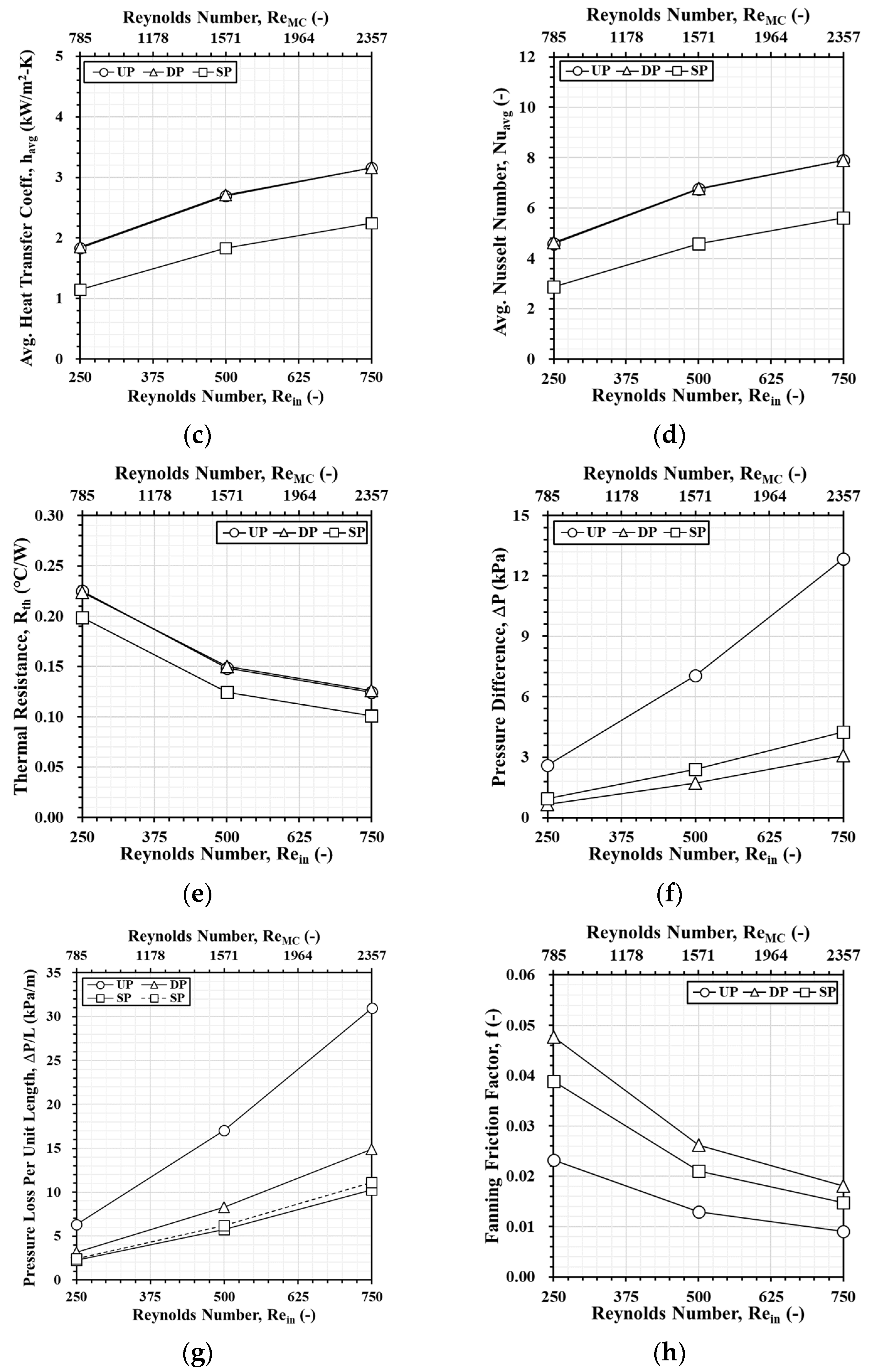
By simulating heat generation in an Intel i9 CPU under high-performance conditions, this study investigates CPU temperature management, which is a critical challenge in computer operation. This study explores the following cooling strategies: (1) varying the flow rate through the heat sinks by adjusting the Reynolds number, (2) integrating aluminum foam into the minichannels, and (3) using nanofluids as alternative cooling fluids. Recognize that the two serpentine channels in the SP model are offset both vertically and horizontally, as shown in Figure 7. The transparent (non-colored) channel is located at the top, whereas the light blue-colored channel is located at the bottom. Since these channels are located in different horizontal planes, their midplanes are designated as planes A-A and B-B where the simulation results will be presented later.

3.1. Pure Water

Figure 8 presents the velocity distribution for three types of heat sinks: UP, DP, and SP channels. The analysis is conducted at various Reynolds numbers using water as the working fluid. Due to the larger cross-sectional area of the flow guide, the local flow velocity increases as the fluid enters the channels. For a specific flow rate into the flow guide, the fluid velocity through the dual channel model is half of that through the single channel. At Reynolds numbers (Rein) of 250, 500, and 750, the velocity trends differ across the models. At Rein = 250, velocity changes are relatively gradual, with the highest velocity in the single channel reaching around 0.5 m/s. As the Reynolds number increases to 500, the velocity in the single channel rises to about 1.3 m/s, while the increase in the staggered channels is insignificant. At Rein = 750, the velocity in the single channel further increases to approximately 2.6 m/s, whereas the staggered channels experience only a small increase to around 1.3 m/s.
Figure 9 shows the temperature distributions for the cases presented in Figure 8. As the Reynolds number increases, the maximum temperature in all three heat sink models decreases significantly, and the temperature distribution becomes more uniform. At a Reynolds number of 250, the maximum temperature in the UP channel is about 89.4 °C, while the DP channel is similar, and the SP channel has a lower maximum of 85.4 °C. An umbrella-shaped temperature distribution appears in the upstream flow guide due to the fact that the fluid entering the flow guide inlet has to squeeze into the smaller channel inlet. The presence of local high pressure before the fluid enters the channel causes a reversal of flow, directly resulting in the umbrella-shaped temperature distribution. As the Reynolds number increases, the umbrella-shaped temperature distribution becomes less pronounced, as higher Reynolds numbers enable the channel to carry away more heat, resulting in a lower and more uniform temperature in the upstream flow guide. At a Reynolds number of 500, the maximum temperature drops significantly. In both the UP and DP channels, it reaches about 67 °C, while the SP channels result in a lower maximum of around 63 °C. As the Rein increases to 750, the temperature distribution becomes even more uniform. The aforementioned maximum temperatures reduce to about 58 °C and around 54 °C, respectively. In brief, the SP channel model exhibits superior heat dissipation at all Reynolds numbers. This is primarily due to the greater contact area between the fluid and the heat sink. This increase in contact area allows for more efficient heat exchange, further enhancing the heat dissipation performance.
Figure 10 compiles the performance of the three types of heat sinks for the cases presented in Figure 8 and Figure 9. In these figures, the primary abscissa represents the Reynolds number (Rein) defined using the conduit diameter, while the secondary abscissa shows the Reynolds number (ReMC) based on the hydraulic diameter of the minichannel. Figure 10a,b show the variation in maximum and average CPU top surface temperatures with respect to Reynolds number. As the Reynolds number increases, the maximum and average temperatures of all three heat sink models decrease. Among them, the maximum and average CPU top surface temperatures of the UP and DP channel models are similar and higher than those of the SP channel at all Reynolds numbers. This confirms that the SP channel model performs the best in terms of heat dissipation. Figure 10c,d show the variation in heat transfer coefficient and Nusselt number with respect to Reynolds number. The heat transfer coefficient and Nusselt number of the UP and DP channel models are similar. Both models increase consistently with the Reynolds number. In contrast, the heat transfer coefficient and Nusselt number for the SP channels are lower at the same Reynolds number and show a smaller increase. At first glance, one might wrongly assume that the SP model performs poorly based on these values. However, one should not jump to conclusions too quickly. In fact, the SP channels have a contact area that is approximately double that of the UP and DP models. This inevitably results in a lower heat transfer coefficient and Nusselt number. Figure 10e shows the corresponding variation in thermal resistance. Again, the thermal resistance of the UP and DP channels is similar and decreases with Reynolds number. The SP channels exhibit the lowest thermal resistance at all Reynolds numbers, indicating better heat dissipation performance. Figure 10f shows the variation in pressure difference between the channel inlet and outlet. As Reynolds number increases, the pressure difference increases. The SP channels exhibit a slightly higher pressure difference than the DP channels. The UP channel exhibits a significantly higher pressure difference, postulating that a two-channel model can effectively reduce the pressure difference, allowing for the use of a lower-power pump and reducing operating costs. On the other hand, Figure 10g shows the variation in pressure loss per unit length. The parameter also consistently increases with Reynolds number, with the UP channel exhibiting the highest values and the SP channels the lowest. Since the lower channel in the SP model is slightly shorter in length, this normalized pressure loss results in a slightly higher pressure loss per unit length in the lower channel (represented by broken lines) compared to the upper channel (solid lines). Figure 10h shows the corresponding variation in the Fanning friction factor. At Reynolds numbers 250, 500, and 750, the Fanning friction factor is the lowest for the UP channel, followed by the SP channels, and highest for the DP channel. Although the Fanning friction factor decreases with the Reynolds number for two-channel models, the SP model does exhibit lower flow resistance than the DP model.

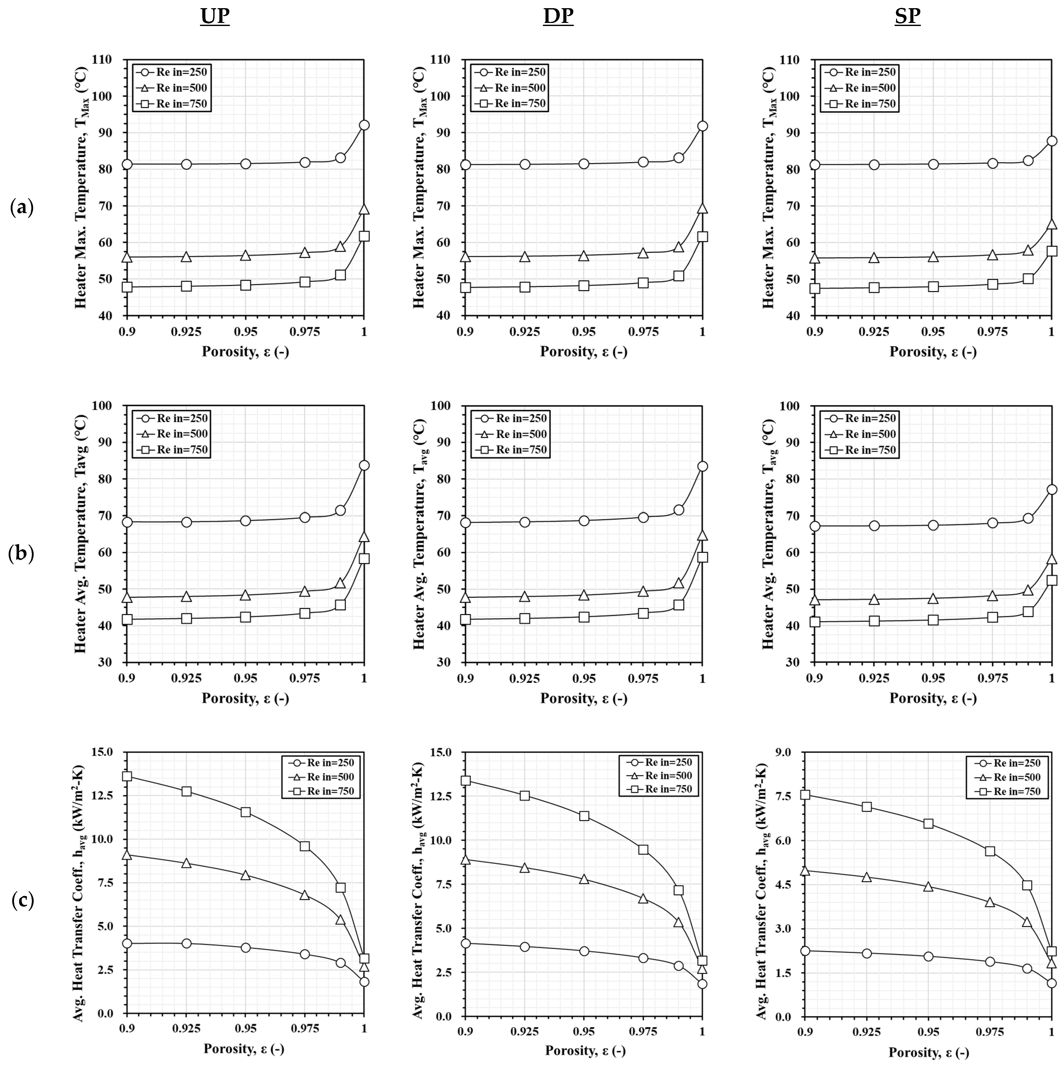
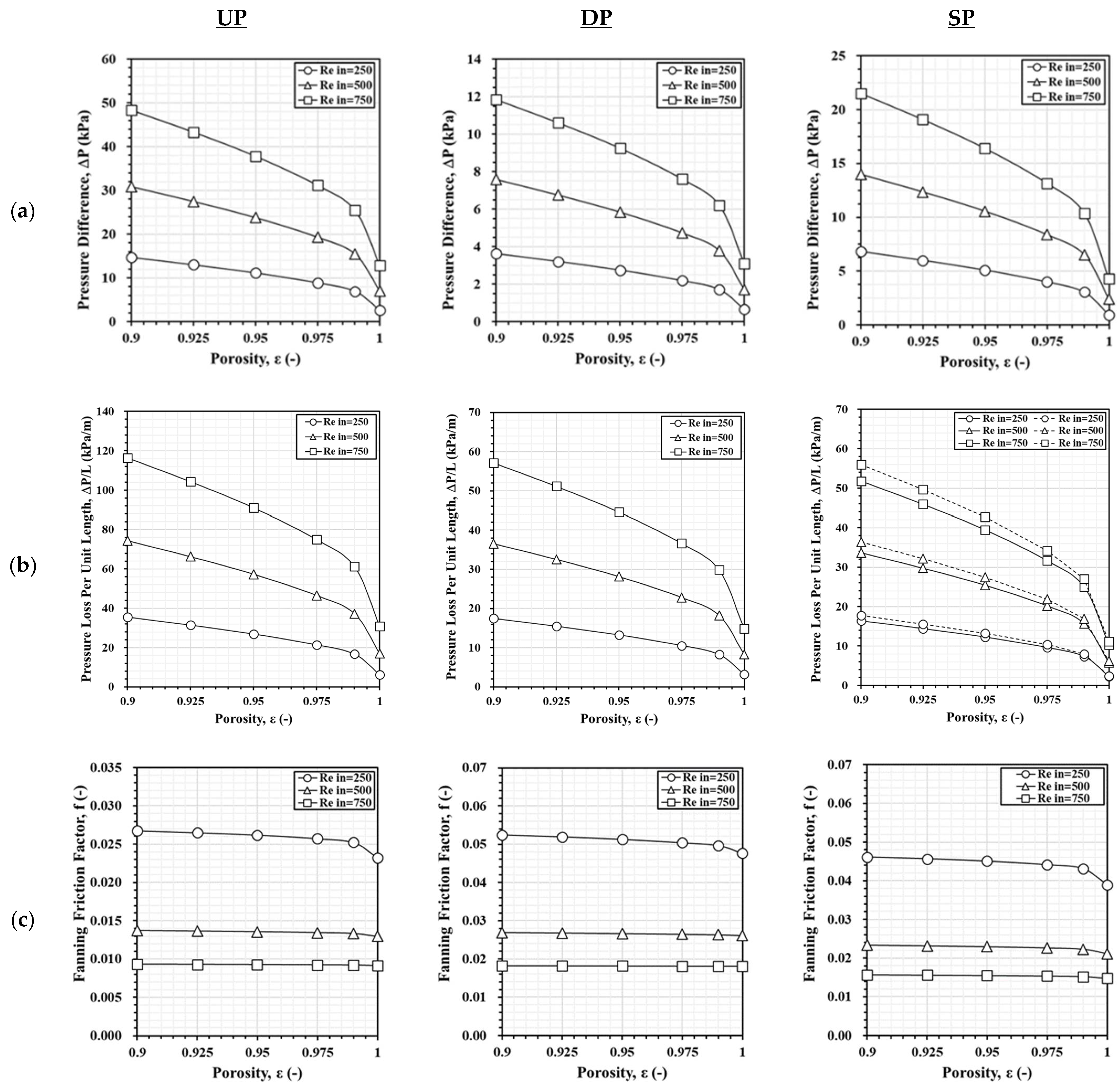
3.2. Pure Water with Aluminum Foam

Figure 11 compares the thermal performance of the three heat sink models using pure water as the fluid, with porosities ranging from ε =1 to 0.9. Figure 11a,b show the variation in the maximum and average CPU top surface temperatures. As Reynolds number increases and porosity decreases, both these temperatures decrease significantly. Observation suggests that at ε = 1, the SP model offers the best heat dissipation, although the difference is not very significant. As porosity decreases, the performance differences among these three models become smaller. Figure 11c,d show the heat transfer coefficient and Nusselt number for different values of porosity and Reynolds number. For all models, as porosity decreases from 1 to 0.9, the heat transfer coefficient and Nusselt number increase. Increasing the Reynolds number further increases their values. Comparison reveals that the heat transfer coefficient and Nusselt number of the UP and DP model are similar whereas those for the SP are clearly much lower. Figure 11e shows that both higher Reynolds number and lower porosity serve to reduce thermal resistance. Apparently, the UP and DP channels exhibit similar thermal resistance. At ε = 1, the SP channels provide the best heat dissipation effect, but as porosity decreases, the differences between these models become less significant.
Figure 12 compares the hydraulic performance of the three heat sink models using pure water as the fluid. Figure 12a,b examine the effects of Reynolds number and porosity on the pressure difference and pressure loss per unit length of the heat sinks. As Reynolds number increases and porosity decreases, both parameters rise for all models. The UP channel has the highest pressure difference and pressure loss per unit length, while the SP channels experience higher values than the DP channels. Evidently, two-channel models can effectively reduce pressure differences, thereby allowing for lower pump power and cost reduction. In the SP configuration, the shorter lower channel exhibits slightly higher pressure loss per unit length due to its reduced path length. Figure 12c shows the Fanning friction factor. As porosity decreases from 1 to 0.9, it increases slightly for all heat sink models. This finding reveals that the SP channels have lower flow resistance than the DP channel.
By now, one should be able to recognize that not all eight parameters need to be examined individually, as some show trends of high resemblance. Unless exact values are required, selecting one of the closely related parameters provides sufficient insight. For brevity, the later part of this paper will focus on the maximum CPU top surface temperature rather than discussing both the maximum and average temperatures. Similarly, the heat transfer coefficient, thermal resistance, and pressure loss are excluded for the same reason.

3.3. Improvement of Al2O3 Nanofluids

Figure 13 compares the performance of UP, DP, and SP channels using Al2O3 nanofluid under different Reynolds numbers and nanofluid volume fractions (Φ = 0–5%). Figure 13a shows that increasing the Reynolds number and nanofluid volume fraction lowers the maximum CPU top surface temperature. However, at volume fractions above 4%, the increase in the nanofluid viscosity actually leads to the reduction in heat dissipation and, therefore, slightly raises the temperatures. The UP and DP channels exhibit similar trends. As the volume fraction increases from 0% to 4%, at Reynolds numbers of 250, 500, and 750, the maximum temperature of the UP and DP channels drops from 92.1 °C to 83.1 °C, 69.2 °C to 58.1 °C, and 61.8 °C to 49.9 °C, respectively, while for the SP channels, it decreases from 87.9 °C to 82.6 °C, 65.1 °C to 57.5 °C, and 57.6 °C to 49.4 °C. A similar trend is observed for the average temperature, which is at most 14 °C lower than the maximum temperature at Rein = 250. In general, the difference between the maximum and average temperatures is less than 10 °C. For pure water, the SP channels provide better heat dissipation. As the nanofluid volume fraction increases, performance differences among the models diminish.
Figure 13b shows the variation in the Nusselt number for the cases previously discussed. For all configurations, the Nusselt number increases with Reynolds number and nanofluid volume fraction. However, when the volume fraction increases from 4% to 5%, the Nusselt number decreases due to the higher fluid viscosity the nanoparticles cause. Both the UP and DP channels exhibit similar trends. As the Reynolds number increases from 250 to 750, the Nusselt number for the UP and DP channels increases from 4.59 to 7.23, from 6.76 to 14.23, and from 7.9 to 19.78. For the SP channels, it increases from 2.88 to 4.07, from 4.59 to 8.33, and from 5.62 to 11.98. The SP channels contribute the lowest Nusselt numbers among these three models owing to their larger heat transfer area.
Figure 13c illustrates that pressure loss per unit length increases for all models as the Al2O3 volume fraction rises from 0% to 5%. The UP channel consistently shows the highest pressure loss per unit length, the SP channels the lowest, and the DP channels fall in between. As Reynolds number increases, this parameter also rises noticeably. For the UP channel, it increases from 6.29 kPa/m to 7.04 kPa/m, from 17.02 kPa/m to 19.18 kPa/m, and from 30.97 kPa/m to 34.85 kPa/m at Reynolds numbers of 250, 500, and 750, respectively. For the DP channels, it rises from 3.15 kPa/m to 3.53 kPa/m, from 8.29 kPa/m to 9.35 kPa/m, and from 14.89 kPa/m to 16.75 kPa/m. In the SP model, the upper channel (solid line) exhibits slightly lower pressure loss than the lower channel (broken line) due to its longer length. Through measurement, the lengths of the upper and lower channels are 0.41 m and 0.38 m, respectively. For the lower channel in the SP model, this parameter increases from 2.26 kPa/m to 2.74 kPa/m, from 5.76 kPa/m to 7.02 kPa/m, and from 10.28 kPa/m to 12.51 kPa/m.
As the volume fraction increases from 0% to 5%, Figure 13d shows that the Fanning friction factor for the UP model changes slightly, ranging from 0.023 to 0.013 and to 0.009 at Reynolds numbers of 250, 500, and 750, respectively. For the DP model, it increases from 0.047 to 0.056, from 0.026 to 0.031, and from 0.018 to 0.021. For the SP model, the Fanning friction factor increases from 0.038 to 0.046, from 0.021 to 0.023, and from 0.014 to 0.016. As the volume fraction decreases and the Reynolds number increases, the Fanning friction factor decreases for all models. The UP model offers a lower Fanning friction factor than the two-channel models. Between the two-channel models, the SP channels offer lower value.

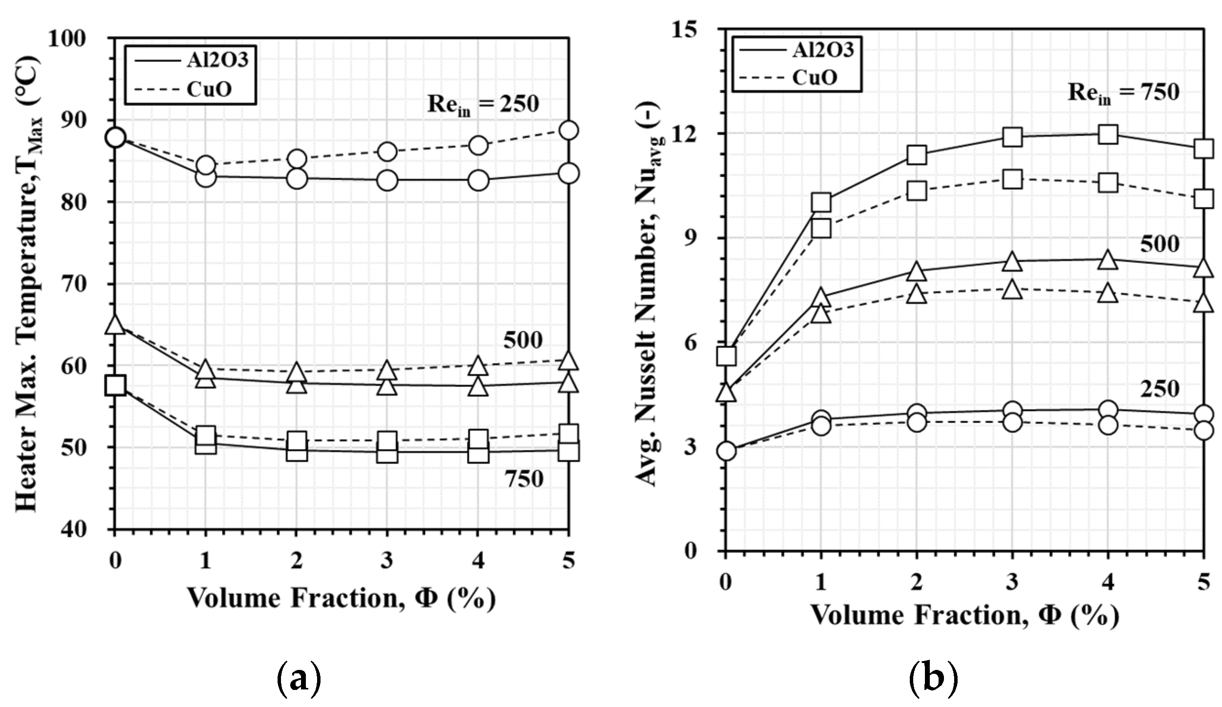
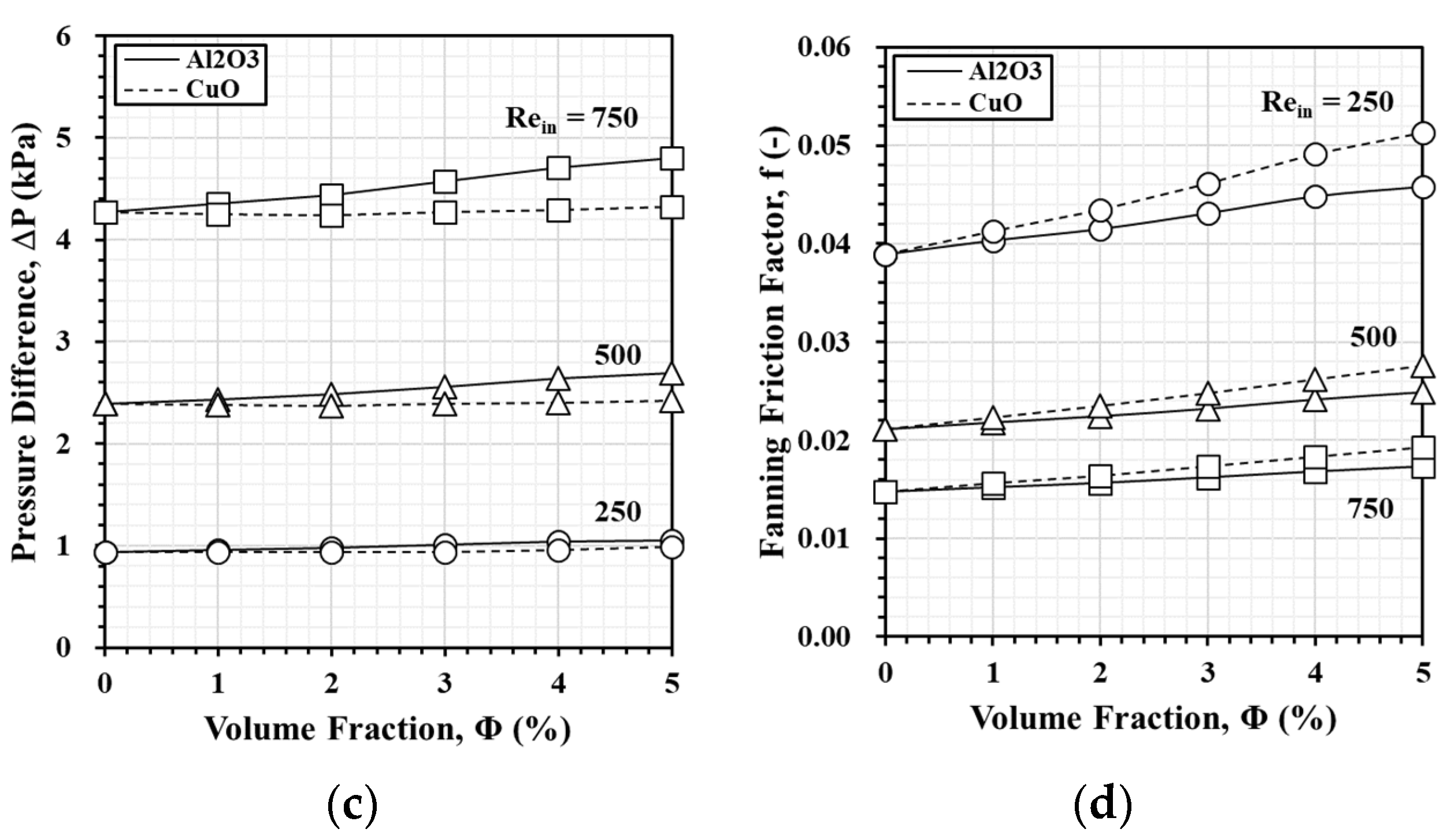
3.4. Comparison of Al2O3 and CuO Nanofluids

Based on the simulation results, the SP model demonstrates the lowest pressure loss per unit length among the models examined, while its maximum and average temperatures are comparable to those of the UP and DP models. Therefore, this model is selected to compare the heat sink performance using two different nanofluids, Al2O3 and CuO, as working fluids at different Reynolds numbers and nanofluid volume fractions (Φ = 0–5%).
The solid lines in Figure 14 refer to the Al2O3 nanofluid, while the broken line refers to the CuO nanofluid. The circular, triangular, and square symbols are intentionally added to each line to indicate different Reynolds numbers. Figure 14a shows the variation in maximum CPU top surface temperature. Within the ranges investigated, as the Reynolds number and nanofluid volume fraction increase, the maximum temperature generally decreases. The lowest maximum temperature occurs at 4% volume fraction for Al2O3 and 2% for CuO. Further increases in volume fraction raise the temperature. Although not shown here, current simulations show that the average temperature and thermal resistance follow similar trends. Having a lower specific heat capacity, CuO nanofluid absorbs heat efficiently at a lower volume fraction, achieving optimal cooling at 2%. Al2O3 requires 4% to reach peak cooling performance because of its comparatively higher specific heat capacity. At the same conditions, Al2O3 results in lower temperatures than CuO, indicating superior heat dissipation. Figure 14b presents the Nusselt number variations for the two nanofluids. The Nusselt number increases with volume fraction and Reynolds number. For Al2O3, it peaks at approximately 4%, while for CuO, the maximum occurs at around 3%. These differences result from the values of their specific heat capacity. Although not shown here, current results show that the average heat transfer coefficient on the CPU top surface follows similar trends. At the same volume fraction and Reynolds number, Al2O3 has a higher heat transfer coefficient and Nusselt number than CuO, confirming its superior heat dissipation performance.
Figure 14c shows the pressure difference between the regions immediately upstream and downstream of the SP channel inlet and outlet for both nanofluids. As the volume fraction increases from 0% to 5%, the pressure difference for Al2O3 nanofluid increases slightly, reaching 1.05 kPa, 2.69 kPa, and 4.81 kPa at Reynolds numbers 250, 500, and 750, respectively. In contrast, the pressure difference for CuO nanofluid remains nearly constant. For both the nanofluids, the pressure difference increases significantly with the Reynolds number. Under the same conditions, Al2O3 exhibits slightly higher pressure differences due to its lower overall density. Figure 14d shows that the Fanning friction factor decreases with increasing Reynolds number or decreasing volume fraction. A higher volume fraction leads to a higher Fanning friction factor. At the same Reynolds number and volume fraction, Al2O3 consistently produces a lower Fanning friction factor than CuO, indicating that Al2O3 nanofluid experiences less frictional resistance and clearly contributes to lower flow resistance.
Although the pressure loss of Al2O3 nanofluid is slightly higher than that of CuO nanofluid, it has consistently demonstrated superior performance in thermal management. Overall, Al2O3 nanofluid demonstrates better cooling capability, making it more suitable as the working fluid for heat dissipation applications in this study. This assertion will be further substantiated by the PEC analysis presented later in the article. Note that the appropriate volume fraction is crucial for enhancing cooling performance. Excessively high volume fractions can negatively impact the heat dissipation effect. It is, therefore, essential to select the optimal volume fraction of nanofluid for efficient cooling performance in practical applications.

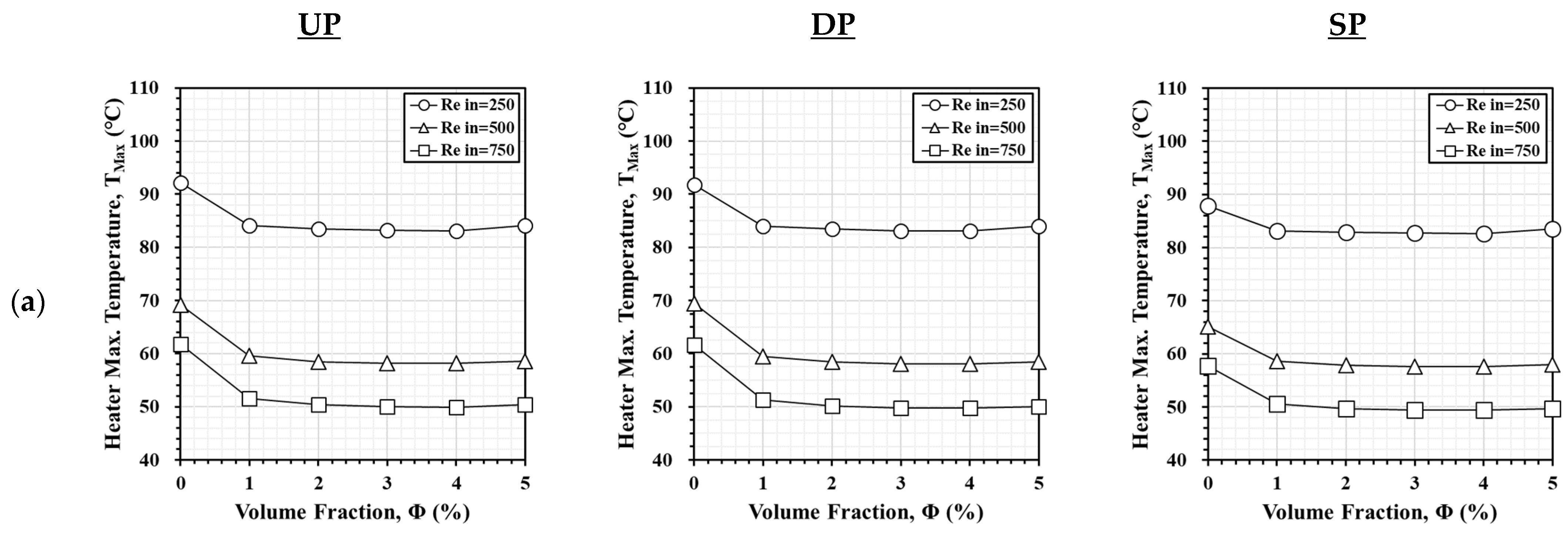
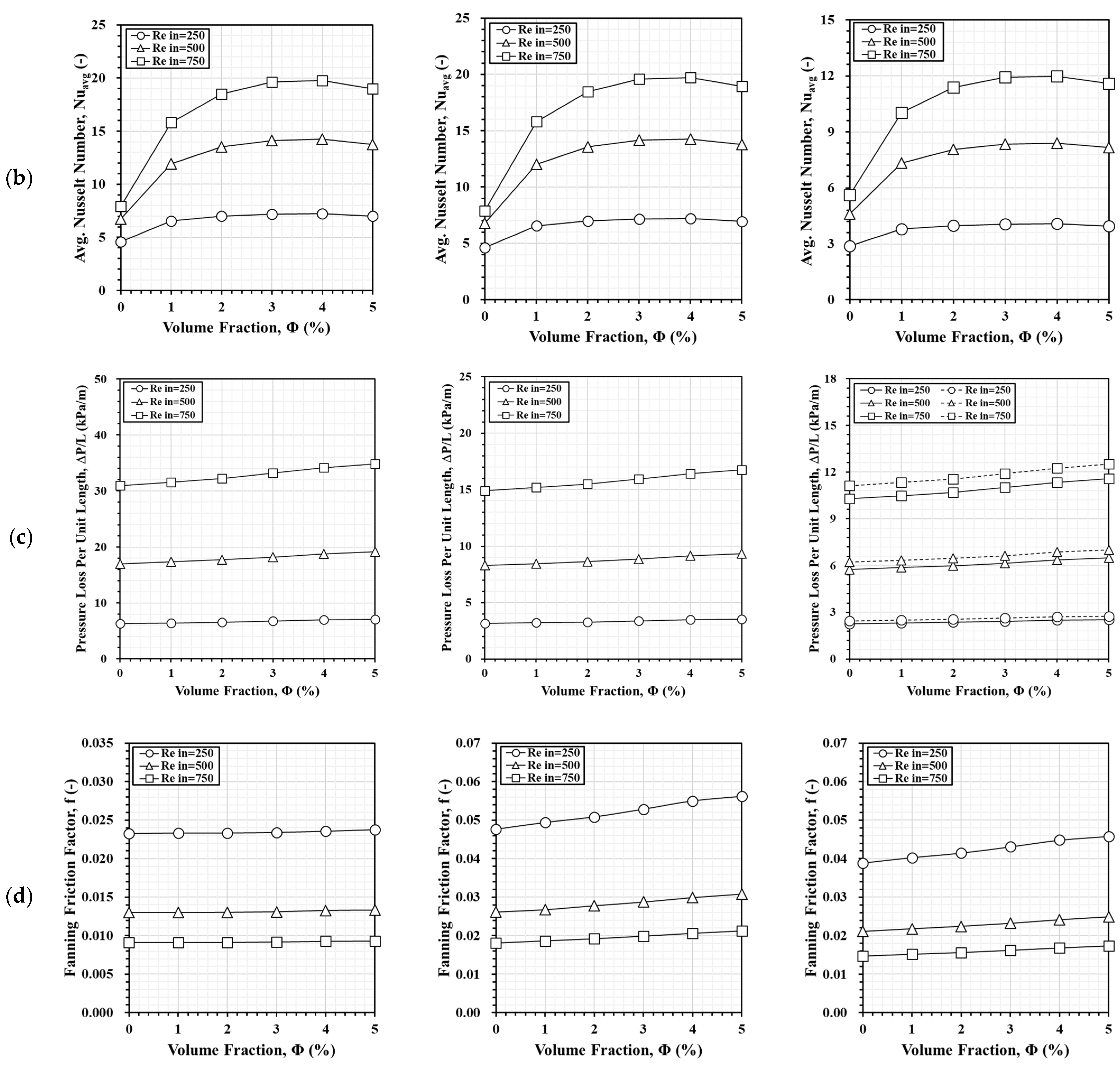
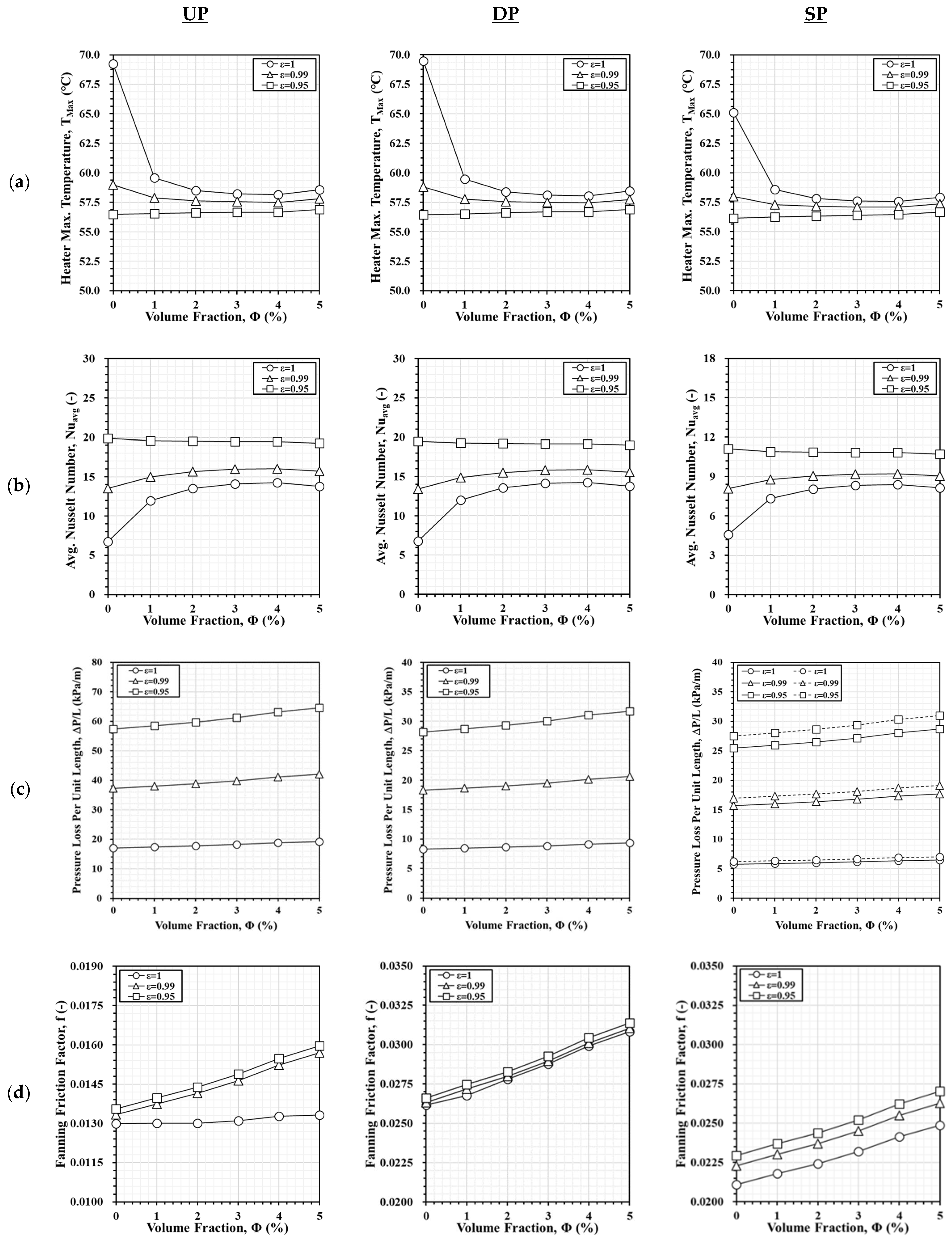
3.5. Combination of Al2O3 Nanofluid with Aluminum Foam

When a computer operates under a high load operation, its i9 CPU temperature should typically range between 65 °C and 80 °C. According to the simulation results in Figure 14, the CPU temperature exceeds this range when Rein = 250, whereas it falls below it when Rein = 750. Introducing nanofluids at these Reynolds numbers is not reasonable. Instead, Rein = 500 appears to correspond to a more nanofluid flow rate. Therefore, Rein = 500 is selected here to investigate the performance of Al2O3 nanofluid at different volume fractions and aluminum foam porosities.
Figure 15a shows that the maximum CPU top surface temperatures for the UP and DP channels are similar, while the SP channels have slightly lower temperatures. When ε = 1, increasing the volume fraction from 1% to 5% lowers the CPU top surface temperature. The maximum value decreases until it reaches its lowest point at 4%, after which it slightly increases. A similar trend appears at a foam porosity of 0.99. When the porosity is 0.95, the variation in maximum temperature becomes quite insignificant. As porosity decreases, the impact of nanofluid volume fraction on cooling weakens. The SP channels consistently show lower maximum temperatures, confirming their superior heat dissipation. The UP and DP channels exhibit similar trends in Nusselt numbers, as shown in Figure 15b. At ε = 1, increasing the volume fraction from 1% to 5% raises the Nusselt number until it peaks at 4% before slightly decreasing. When the porosity is 0.99, the Nusselt number follows the same trend as before, reaching its highest value at a volume fraction of 4% and then slightly decreasing at 5%. The variations are minimal when the porosity is equal to 0.95, though a slight downward trend is observed. These results show that lower porosity reduces the impact of nanofluid volume fraction on heat transfer enhancement.
The variation in pressure loss per unit length with volume fraction and porosity is shown in Figure 15c. As the volume fraction increases, pressure loss per unit length increases for all models, regardless of porosity. Even so, decreasing porosity appears to make pressure loss more sensitive to volume fraction. The UP model has the highest pressure loss, while the SP model has the lowest, with the DP model in between. In this figure, the broken lines (lower channel) are consistently higher than the solid lines (upper channel) for the SP channels due to their different lengths. Figure 15d shows that the Fanning friction factor increases with nanofluid volume fraction and decreases with foam porosity across all models. The UP channel exhibits the lowest Fanning friction factor, while the DP channel has a higher friction factor compared to the SP channel.

3.6. Performance Evaluation

Various parameters, such as CPU temperatures, Nusselt number, pressure losses, and Fanning friction factor, have been previously used to evaluate the major performance of each heat sink model. However, these parameters are incapable of fully reflecting the overall model efficiency. To address this, an overall indexed so-called PEC is thus introduced. The PEC integrates key performance parameters to provide a more comprehensive measure of heat dissipation efficiency that enables a clearer comparison of different heat sink models.
Figure 16 compares the PEC performance of the three heat sink models using pure water as the coolant. The UP heat sink serves as the reference, with its PEC value set to 1 at Reynolds numbers 250, 500, and 750. There are three PEC = 1 values corresponding to the three Reynolds numbers. A PEC value greater than 1 indicates superior performance compared to the UP model (the reference model) at its corresponding Reynolds number. Both the DP and SP heat sinks consistently achieve PEC values greater than 1 across all Reynolds numbers, confirming their enhanced heat dissipation efficiency. Among the three models, the UP model has the lowest PEC, indicating its least effective thermal performance. As the Reynolds number increases, the PEC of the DP model remains stable at approximately 1.6. In contrast, the PEC of the SP model increases from 1.64 to 1.87 as the Reynolds number rises from 250 to 750, highlighting its growing performance advantage over the UP model at higher Reynolds numbers. Overall, the SP model demonstrates the highest heat dissipation performance, followed by the DP model.
Figure 17 compares the PEC performance of the three heat sink models using pure water as the coolant with the channels filled with aluminum foam of different porosities. The result for the UP model at a Reynolds number of 250 is associated with PEC = 1. This PEC value serves as the standard reference point in these figures. It provides a consistent basis for comparing different scenarios. As porosity decreases from 1 to 0.9, the PEC for the UP model increases from approximately 1 to 2.09, 3.32, and 4.27. Following a similar trend, the PEC values for the DP model rise from about 1.59 to 6.07, while the SP model improves from around 1.64 to 6.17. These results indicate that lower porosity and higher Reynolds numbers enhance heat dissipation performance. At the same Reynolds number and porosity, the SP model achieves the highest PEC, followed by the DP model, with the UP model performing the worst. This confirms that the SP model provides the best heat dissipation when using porous aluminum foam and pure water as the coolant.
Integrating aluminum foams into microchannel structures offers significant potential for enhancing CPU cooling by improving the rate of heat removal. The high surface area and flow-disrupting characteristics of aluminum foam promote superior heat transfer, making it an attractive option for electronics cooling. However, several technical challenges must be addressed to enable practical implementation. Achieving precise placement and uniform pore distribution within narrow channels is difficult and may lead to uneven flow or increased pressure drop. Based on current simulation results, the variation in foam porosity does not appear to play a critical role in heat removal effectiveness. Spraying foam directly into the channels is a potential fabrication method, though it may result in incomplete contact with channel walls and reduced thermal performance. Nonetheless, the presence of coolant can help mitigate this imperfection. Additionally, thermal expansion mismatch between the foam and channel materials can lead to mechanical degradation over time. Embedding the foam within a larger metal block may help reduce this risk. Advanced fabrication methods such as in situ foaming, additive manufacturing, surface treatments to improve thermal contact, and tailored material selection offer promising paths to overcome these limitations. With precise control over manufacturing and interface engineering, scalable and reliable integration of metal foams into microchannels is increasingly achievable.
Figure 18 compares the PEC performance of the heat sink models using Al2O3 nanofluid at varying Reynolds numbers and nanofluid volume fractions. When using pure water as the coolant (Φ = 0%), the UP model is treated as the baseline reference for performance comparison at Reynolds numbers 250, 500, and 750. The performance of other configurations or flow conditions is compared against this UP model at the same Reynolds number. Regardless of the heat sink structure, PEC increases with volume fraction and Reynolds number but starts declining at 3–4% volume fraction due to increased effective fluid viscosity that, in turn, hinders heat dissipation. The DP and SP models exhibit higher PEC values than the UP model. At Reynolds numbers 250 and 500, the DP and SP models show similar performance, but at 750, the SP model slightly outperforms the DP model. Once again, the SP model has shown its superiority in terms of PEC performance over the other two models.
Figure 19 compares the PEC performance of the SP model using Al2O3 and CuO nanofluids at different Reynolds numbers and volume fractions (Φ = 0–5%). Once again, the symbols are purposely added to each line to indicate different Reynolds numbers. When pure water (Φ = 0%) is used as the coolant at Reynolds numbers 250, 500, and 750, these cases serve as the baseline references for performance comparison. The performance of individual nanofluid with different volume fractions and flow conditions is then compared against these baseline cases at the same Reynolds number. It is observed that PEC, in general, increases with both volume fraction and Reynolds number. However, it declines when the volume fraction goes beyond 3–4% for Al2O3 and 2–3% for CuO due to their increase in effective fluid viscosity. Because of its lower specific heat capacity, CuO absorbs heat more effectively at lower volume fractions and achieves its maximum PEC earlier. In contrast, Al2O3 requires a greater volume fraction to reach maximum PEC owing to its higher specific heat capacity. Remarkably, the PEC for Al2O3 nanofluid consistently exceeds that for CuO nanofluid under the same Reynolds number and volume fraction. This again confirms that the Al2O3 nanofluid offers better heat dissipation performance.

4. Conclusions

This study predominantly relies on numerical simulations to analyze three heat sink models with UP, DP, and SP channels. In addition to using water as the coolant, the feasibility of using nanofluids (Al2O3 and CuO) and aluminum foam filling is investigated. Due to limited access to laboratory facilities and resources, experimental validation was not feasible during the course of this work. We acknowledge this limitation and recommend that future research incorporate experimental measurements to further validate and support the findings presented. The key conclusions based on the current study are summarized as follows:
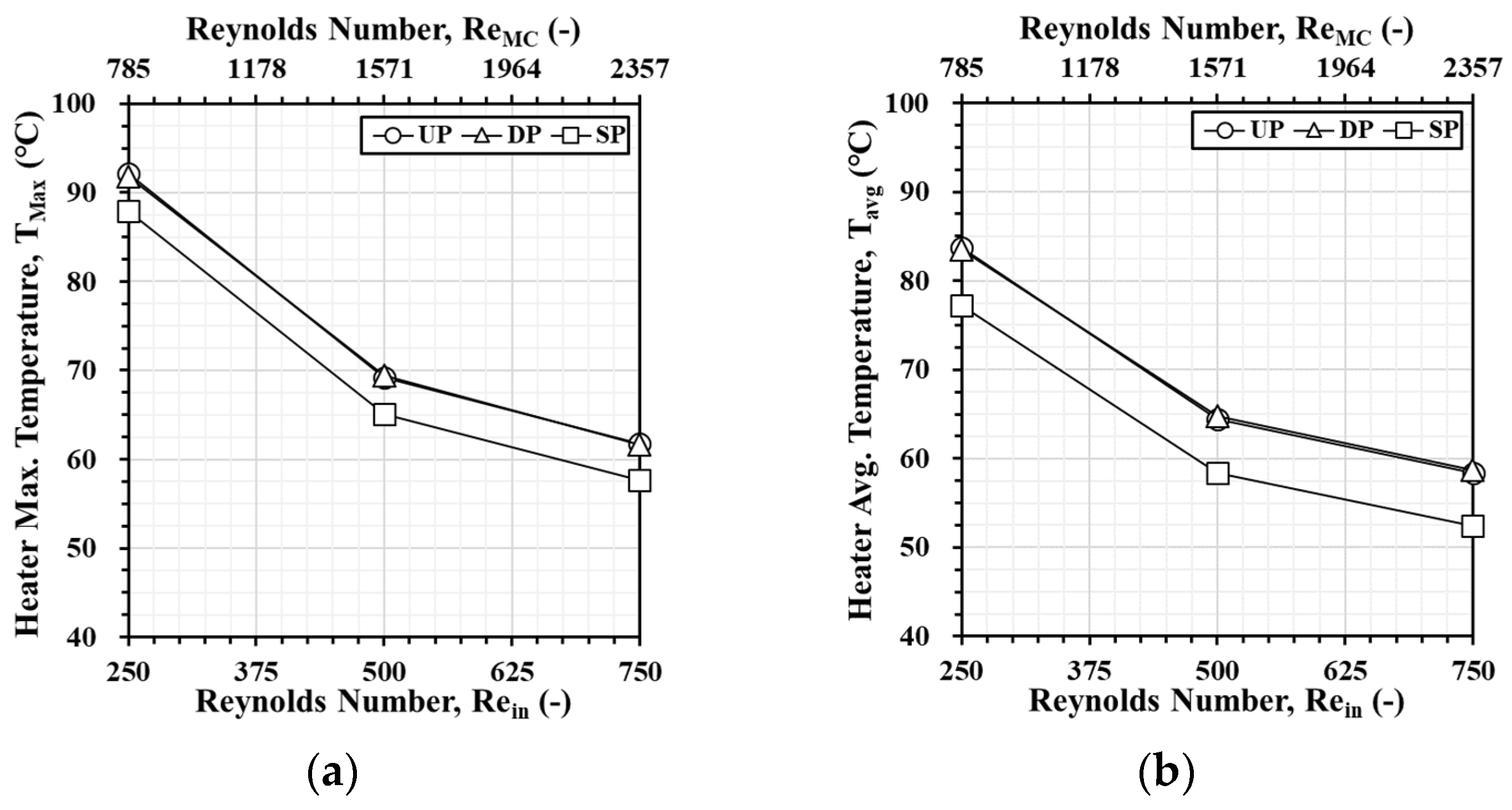
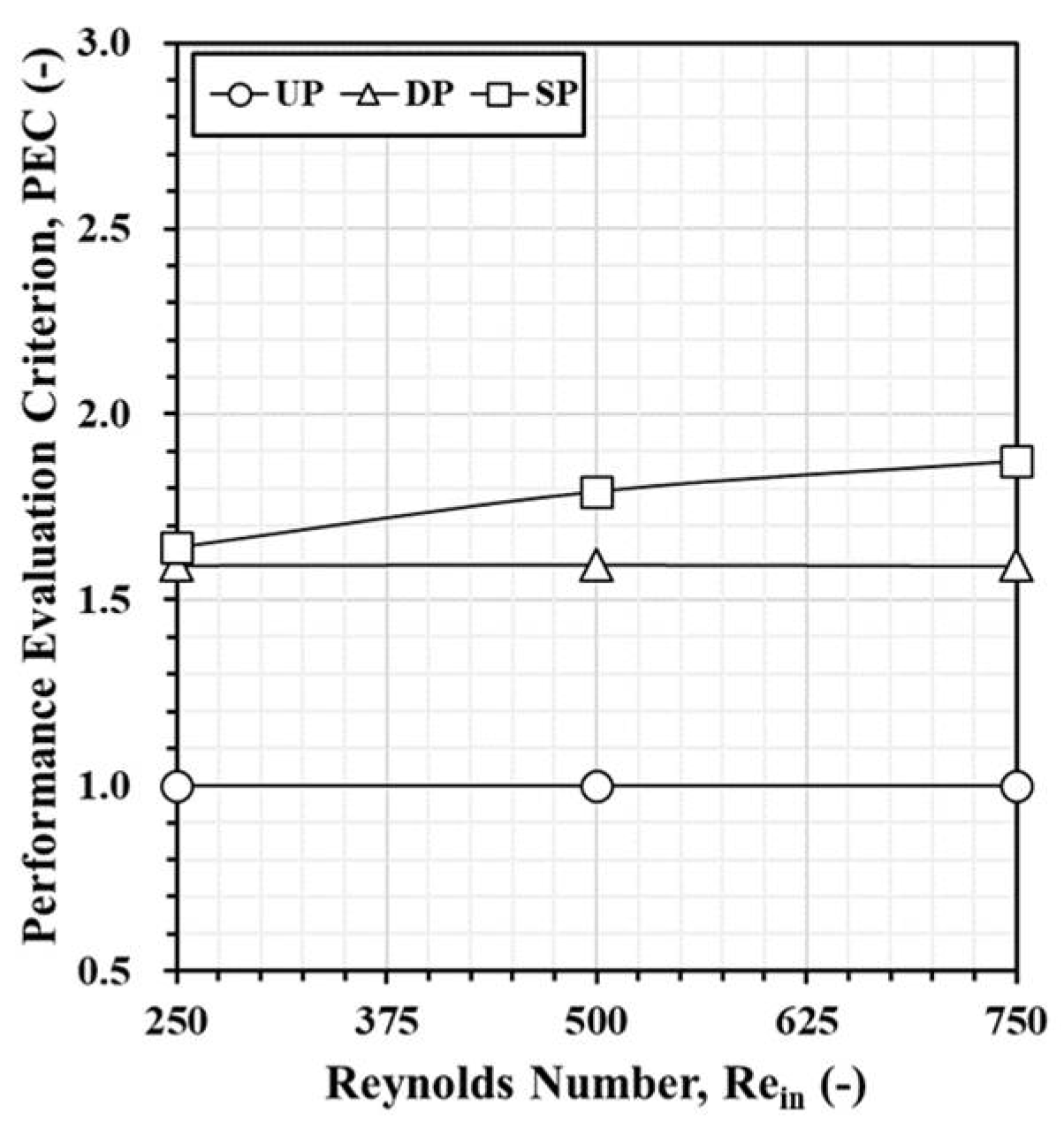
  • The SP model consistently outperforms the UP and DP models for all Reynolds numbers and conditions by offering the highest PEC values, the lowest temperature readings, as well as the lowest pressure loss and frictional resistance. The DP model performs better than the UP model, but it still lags behind the SP model in all performance metrics.
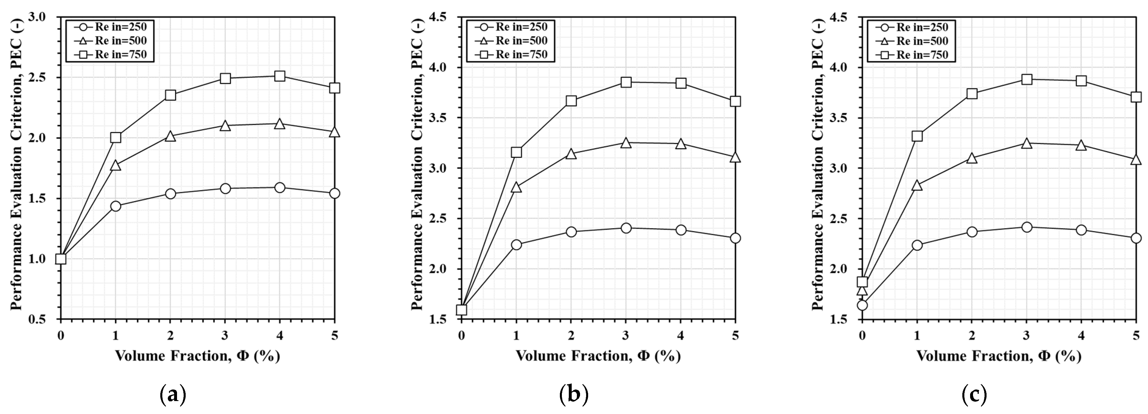
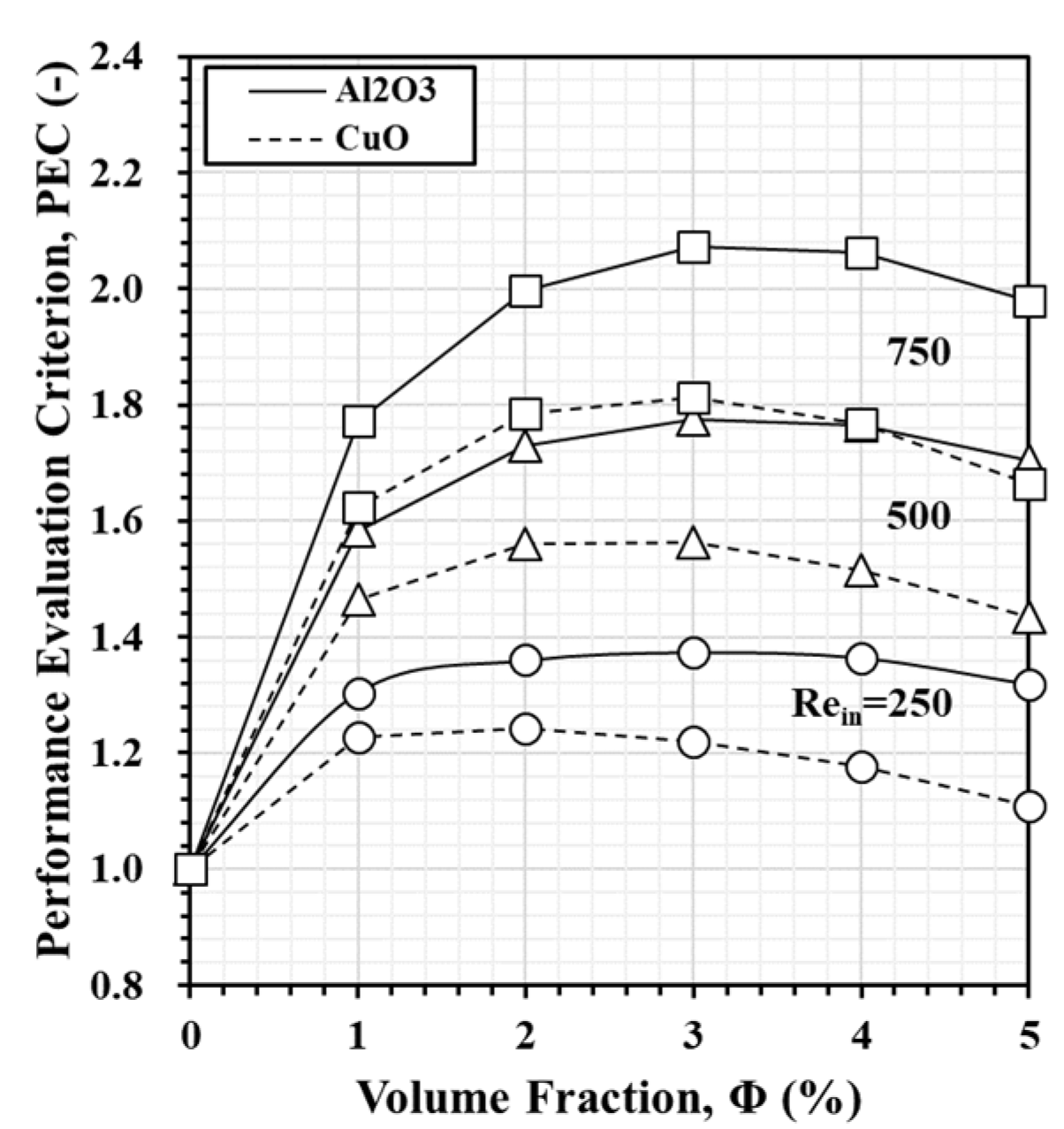
  • Both Al2O3 and CuO nanofluids confirm their significant outperformance over pure water in terms of heat dissipation and PEC. Al2O3 consistently demonstrates better heat dissipation, especially at higher volume fractions. Meanwhile, CuO performs better at lower volume fractions due to its lower specific heat capacity.
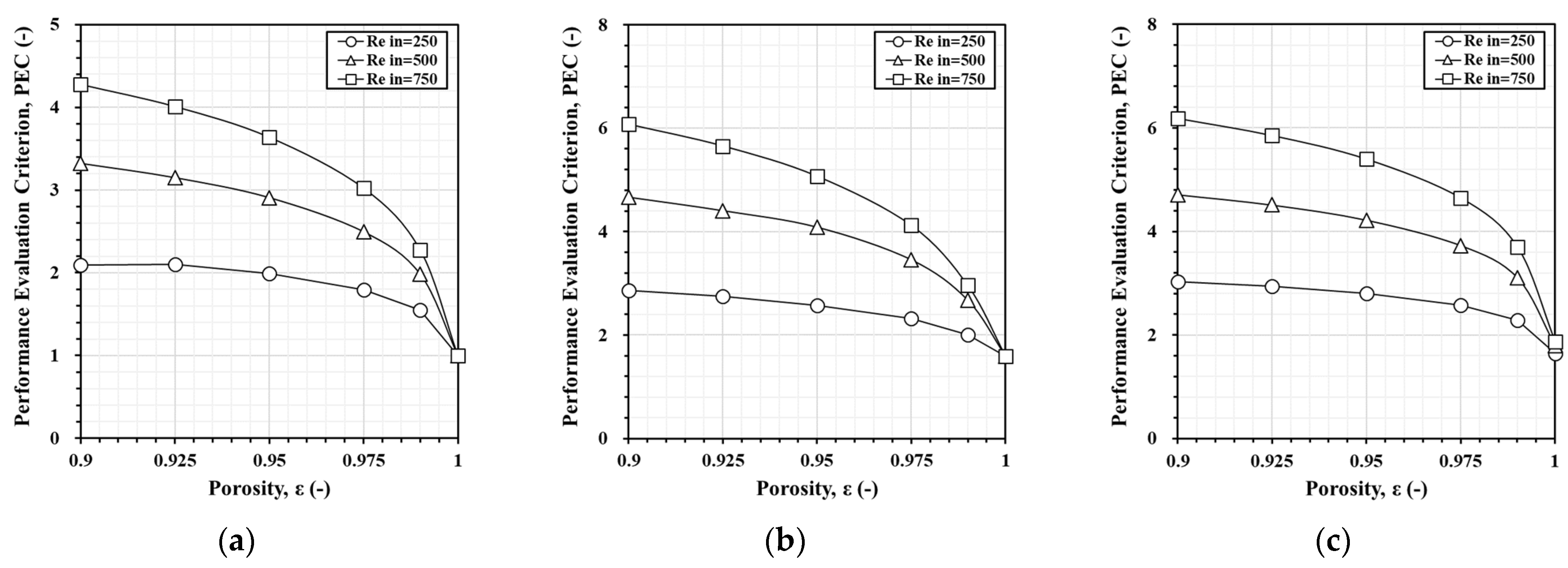
  • Lower foam porosity significantly enhances heat dissipation performance, particularly in the SP and DP models. However, lower porosity increases pressure loss and frictional resistance. Finding the optimal balance between porosity and volume fraction is crucial for efficient heat transfer.
  • Using PEC instead of multiple thermal and flow performance indexes is a better approach, particularly for comparing heat dissipation efficiency across different heat sink models in this study. PEC integrates both thermal performance and flow resistance into a single metric, allowing a more comprehensive and effective evaluation of the overall effectiveness of all three models.
  • Using PEC over a number of thermal and flow performance indexes can be considered a better approach, particularly when comparing the heat dissipation efficiency across different heat sink models in this study. PEC combines both thermal performance and flow resistance into a single metric. This allows a more comprehensive evaluation of the overall effectiveness of all three models.

Author Contributions

Conceptualization, L.L. and J.C.L.; methodology, L.L. and J.C.L.; software, L.L.; data curation, L.L.; writing—original draft preparation, L.L. and J.C.L.; writing—review and editing, J.C.L.; supervision, J.C.L. All authors have read and agreed to the published version of the manuscript.

Funding

This research received no external funding.

Data Availability Statement

The data are contained within the article.

Conflicts of Interest

The authors declare no conflicts of interest.

References

  1. Chu, R.C.; Simons, R.E.; Ellsworth, M.J.; Schmidt, R.R.; Cozzolino, V. Review of cooling technologies for computer products. IEEE Trans. Device Mater. Reliab. 2004, 4, 568–585. [Google Scholar] [CrossRef]
  2. Khalaj, A.H.; Halgamuge, S.K. A Review on efficient thermal management of air-and liquid-cooled data centers: From chip to the cooling system. Appl. Energy 2017, 205, 1165–1188. [Google Scholar] [CrossRef]
  3. Harun, M.A.; Sidik, N.A.C. A review on development of liquid cooling system for central processing unit (CPU). J. Adv. Res. Fluid Mech. Therm. Sci. 2020, 78, 98–113. [Google Scholar] [CrossRef]
  4. Schmidt, R. Challenges in electronic cooling: Opportunities for enhanced thermal management techniques—Microprocessor liquid cooled minichannel heat sink. In Proceedings of the International Conference on Nanochannels, Microchannels, and Minichannels, New York, NY, USA, 24–25 April 2003. [Google Scholar]
  5. Qiu, D.; Cao, L.; Wang, Q.; Hou, F.; Wang, X. Experimental and numerical study of 3D stacked dies under forced air cooling and water immersion cooling. Microelectron. Reliab. 2017, 74, 34–43. [Google Scholar] [CrossRef]
  6. Tuckerman, D.B.; Pease, R.F.W. High-Performance Heat Sinking for VLSI. IEEE Electron Device Lett. 1981, 2, 126–129. [Google Scholar] [CrossRef]
  7. Phillips, R.J. Microchannel heat sinks. Linc. Lab. J. 1988, 1, 31–48. [Google Scholar]
  8. Goodling, J.S. Microchannel heat exchangers: A review. In Proceedings of the SPIE, High Heat Flux Engineering II 1993, San Diego, CA, USA, 11–16 July 1993; SPIE: Washington, DC, USA; pp. 66–82. [Google Scholar]
  9. Steinke, M.E.; Kandlikar, S.G. Single-phase heat transfer enhancement techniques in microchannel and mini-channel flows. In Proceedings of the 2nd International Conference on Microchannels and Minichannels, New York, NY, USA, 17–19 June 2004. [Google Scholar]
  10. Khan, M.G.; Fartaj, A. A review on microchannel heat exchangers and potential applications. Int. J. Energy Res. 2011, 35, 553–582. [Google Scholar] [CrossRef]
  11. Dixit, T.; Ghosh, I. Review of micro-and mini-channel heat sinks and heat exchangers for single phase fluids. Renew. Sustain. Energy Rev. 2015, 41, 1298–1311. [Google Scholar] [CrossRef]
  12. Ramesh, K.N.; Sharma, T.K.; Rao, G.A.P. Latest advancements in heat transfer enhancement in the micro-channel heat sinks: A review. Arch. Comput. Methods Eng. 2021, 28, 3135–3165. [Google Scholar] [CrossRef]
  13. Kandlikar, S.G.; Grande, W.J. Evolution of microchannel flow passages-thermohydraulic performance and fabrication technology. Heat Transf. Eng. 2003, 24, 3–17. [Google Scholar] [CrossRef]
  14. Bhavnani, S.; Narayanan, V.; Qu, W.; Jensen, M.; Kandlikar, S.; Kim, J.; Thome, J. Boiling augmentation with micro/nanostructured surfaces: Current status and research outlook. Nanoscale Microscale Thermophys. Eng. 2014, 18, 197–222. [Google Scholar] [CrossRef]
  15. Sidik, N.A.C.; Muhamad, M.N.A.W.; Japar, W.M.A.A.; Rasid, Z.A. An overview of passive techniques for heat transfer augmentation in microchannel heat sink. Int. Commun. Heat Mass Transf. 2017, 88, 74–83. [Google Scholar] [CrossRef]
  16. Qu, W.; Mudawar, I. Analysis of three-dimensional heat transfer in micro-channel heat sinks. Int. J. Heat Mass Transf. 2002, 45, 3973–3985. [Google Scholar] [CrossRef]
  17. Al-Neama, A.F.; Kapur, N.; Summers, J.; Thompson, H.M. An experimental and numerical investigation of the use of liquid flow in serpentine microchannels for microelectronics cooling. Appl. Therm. Eng. 2017, 116, 709–723. [Google Scholar] [CrossRef]
  18. Zhang, J.F.; Jia, L.; Yang, W.W.; Taler, J.; Oclon, P. Numerical analysis and parametric optimization on flow and heat transfer of a microchannel with longitudinal vortex generators. Int. J. Therm. Sci. 2019, 141, 211–221. [Google Scholar] [CrossRef]
  19. Wang, G.; Chen, T.; Tian, M.; Ding, G. Fluid and heat transfer characteristics of microchannel heat sink with truncated rib on sidewall. Int. J. Heat Mass Transf. 2020, 148, 119142. [Google Scholar] [CrossRef]
  20. Zhang, X.; Ji, Z.; Wang, J.; Lv, X. Research progress on structural optimization design of microchannel heat sinks applied to electronic devices. Appl. Therm. Eng. 2023, 235, 121294. [Google Scholar] [CrossRef]
  21. Choi, S.U.S.; Eastman, J.A. Enhancing thermal conductivity of fluids with nanoparticles. In Proceedings of the ASME International Mechanical Engineering Congress & Exposition, San Francisco, CA, USA, 12–17 November 1995. [Google Scholar]
  22. Lee, J.H.; Hwang, K.S.; Jang, S.P.; Lee, B.H.; Kim, J.H.; Choi, S.U.S.; Choi, C.J. Effective viscosities and thermal conductivities of aqueous nanofluids containing low volume concentrations of Al2O3 nanoparticles. Int. J. Heat Mass Transf. 2008, 51, 2651–2656. [Google Scholar] [CrossRef]
  23. Ho, C.J.; Chen, W.C. An experimental study on thermal performance of Al2O3/water nanofluid in a minichannel heat sink. Appl. Therm. Eng. 2013, 50, 516–522. [Google Scholar] [CrossRef]
  24. Sabaghan, A.; Edalatpour, M.; Moghadam, M.C.; Roohi, E.; Niazmand, H. Nanofluid flow and heat transfer in a microchannel with longitudinal vortex generators: Two-phase numerical simulation. Appl. Therm. Eng. 2016, 100, 179–189. [Google Scholar] [CrossRef]
  25. Arshad, W.; Ali, H.M. Experimental investigation of heat transfer and pressure drop in a straight minichannel heat sink using TiO2 nanofluid. Int. J. Heat Mass Transf. 2017, 110, 248–256. [Google Scholar] [CrossRef]
  26. Moghadasi, H.; Aminian, E.; Saffari, H.; Mahjoorghani, M.; Emamifar, A. Numerical analysis on laminar forced convection improvement of hybrid nanofluid within a U-bend pipe in porous media. Int. J. Mech. Sci. 2020, 179, 105659. [Google Scholar] [CrossRef]
  27. Siricharoenpanich, A.; Wiriyasart, S.; Naphon, P. Study on the thermal dissipation performance of GPU cooling system with nanofluid as coolant. Case Stud. Therm. Eng. 2021, 25, 100904. [Google Scholar] [CrossRef]
  28. Chu, Y.M.; Farooq, U.; Mishra, N.K.; Ahmad, Z.; Zulfiqar, F.; Yasmin, S.; Khan, S.A. CFD analysis of hybrid nanofluid-based microchannel heat sink for electronic chips cooling: Applications in nano-energy thermal devices. Case Stud. Therm. Eng. 2023, 44, 102818. [Google Scholar] [CrossRef]
  29. Hwang, J.J.; Hwang, G.J.; Yeh, R.H.; Chao, C.H. Measurement of interstitial convective heat transfer and frictional drag for flow across metal foams. J. Heat Transf. 2002, 124, 120–129. [Google Scholar] [CrossRef]
  30. Lu, W.; Zhao, C.Y.; Tassou, S.A. Thermal analysis on metal-foam filled heat exchangers. Part I: Metal-foam filled pipes. Int. J. Heat Mass Transf. 2006, 49, 2751–2761. [Google Scholar] [CrossRef]
  31. Li, Y.; Gong, L.; Xu, M.; Joshi, Y. Enhancing the performance of aluminum foam heat sinks through integrated pin fins. Int. J. Heat Mass Transf. 2020, 151, 119376. [Google Scholar] [CrossRef]
  32. Li, Y.; Gong, L.; Ding, B.; Xu, M.; Joshi, Y. Thermal management of power electronics with liquid cooled metal foam heat sink. Int. J. Therm. Sci. 2021, 163, 106796. [Google Scholar] [CrossRef]
  33. Seyf, H.R.; Layeghi, M. Numerical analysis of convective heat transfer from an elliptic pin fin heat sink with and without metal foam insert. J. Heat Transf. 2010, 132, 07140-1–071401-9. [Google Scholar] [CrossRef]
  34. Bayomy, A.M.; Saghir, M.Z.; Yousef, T. Electronic cooling using water flow in aluminum metal foam heat sink: Experimental and numerical approach. Int. J. Therm. Sci. 2016, 109, 182–200. [Google Scholar] [CrossRef]
  35. Alhajaj, Z.; Bayomy, A.M.; Saghir, M.Z.; Rahman, M.M. Flow of nanofluid and hybrid fluid in porous channels: Experimental and numerical approach. Int. J. Thermofluids 2020, 1–2, 100016. [Google Scholar] [CrossRef]
  36. Vafai, K.; Zhu, L. Analysis of two-layered micro-channel heat sink concept in electronic cooling. Int. J. Heat Mass Transf. 1999, 42, 2287–2297. [Google Scholar] [CrossRef]
  37. Wu, J.M.; Zhao, J.Y.; Tseng, K.J. Parametric study on the performance of double-layered microchannels heat sink. Energy Convers. Manag. 2014, 80, 550–560. [Google Scholar] [CrossRef]
  38. Bahiraei, M.; Jamshidmofid, M.; Goodarzi, M. Efficacy of a hybrid nanofluid in a new microchannel heat sink equipped with both secondary channels and ribs. J. Mol. Liq. 2019, 273, 88–98. [Google Scholar] [CrossRef]
  39. Wong, K.-C.; Muezzin, F.N.A. Heat transfer of a parallel flow two-layered microchannel heat sink. Int. Commun. Heat Mass Transf. 2013, 49, 136–140. [Google Scholar] [CrossRef]
  40. Yan, S.; Wang, F.; Hong, J.; Sigmund, O. Topology optimization of microchannel heat sinks using a two-layer model. Int. J. Heat Mass Transf. 2019, 143, 118462. [Google Scholar] [CrossRef]
  41. Lu, B.; Meng, W.J.; Mei, F. Experimental investigation of Cu-based, double-layered, microchannel heat exchangers. J. Micromech. Microeng. 2013, 23, 035017. [Google Scholar] [CrossRef]
  42. Ahmed, H.E.; Ahmed, M.I.; Seder, I.M.; Salman, B.H. Experimental investigation for sequential triangular double-layered microchannel heat sink with nanofluids. Int. Commun. Heat Mass Transf. 2016, 77, 104–115. [Google Scholar] [CrossRef]
  43. Patel, N.; Mehta, H.B. Experimental investigations on a variable channel width double layered minichannel heat sink. Int. J. Heat Mass Transf. 2021, 165, 120633. [Google Scholar] [CrossRef]
  44. Narendran, G.; Mallikarjuna, B.; Nagesha, B.K.; Gnanasekaran, N. Experimental investigation on additive manufactured single and curved double layered microchannel heat sink with nanofluids. Heat Mass Transf. 2023, 59, 1311–1332. [Google Scholar] [CrossRef]
  45. Hung, T.C.; Yan, W.M.; Li, W.P. Analysis of heat transfer characteristics of double-layered microchannel heat sink. Int. J. Heat Mass Transf. 2012, 55, 3090–3099. [Google Scholar] [CrossRef]
  46. Hung, T.C.; Yan, W.M. Enhancement of thermal performance in double-layered microchannel heat sink with nanofluids. Int. J. Heat Mass Transf. 2012, 55, 3225–3238. [Google Scholar] [CrossRef]
  47. Hung, T.C.; Yan, W.M.; Wang, X.D.; Huang, Y.X. Optimal design of geometric parameters of double-layered microchannel heat sinks. Int. J. Heat Mass Transf. 2012, 55, 3262–3272. [Google Scholar] [CrossRef]
  48. Deng, D.; Pi, G.; Zhang, W.; Wang, P.; Fu, T. Numerical study of double-layered microchannel heat sinks with different cross-sectional shapes. Entropy 2018, 21, 16. [Google Scholar] [CrossRef] [PubMed]
  49. Dai, H.; Chen, W. Numerical investigation of heat transfer in the double-layered minichannel with microencapsulated phase change suspension. Int. Commun. Heat Mass Transf. 2020, 119, 104918. [Google Scholar] [CrossRef]
  50. Wang, S.L.; Chen, L.Y.; Zhang, B.X.; Yang, Y.R.; Wang, X.D. A new design of double-layered microchannel heat sinks with wavy microchannels and porous-ribs. J. Therm. Anal. Calorim. 2020, 141, 547–558. [Google Scholar] [CrossRef]
  51. Sarvar-Ardeh, S.; Rafee, R.; Rashidi, S. Hybrid nanofluids with temperature-dependent properties for use in double-layered microchannel heat sink; hydrothermal investigation. J. Taiwan Inst. Chem. Eng. 2021, 124, 53–62. [Google Scholar] [CrossRef]
  52. Derakhshanpour, K.; Kamali, R.; Eslami, M. Improving performance of single and double-layered microchannel heat sinks by cylindrical ribs: A numerical investigation of geometric parameters. Int. Commun. Heat Mass Transf. 2021, 126, 105440. [Google Scholar] [CrossRef]
  53. Thompson, S.M.; Cheng, P.; Ma, H.B. An experimental investigation of a three-dimensional flat-plate oscillating heat pipe with staggered microchannels. Int. J. Heat Mass Transf. 2011, 54, 3951–3959. [Google Scholar] [CrossRef]
  54. Zhai, Y.; Xia, G.; Li, Z.; Wang, H. A novel flow arrangement of staggered flow in double-layered microchannel heat sinks for microelectronic cooling. Int. Commun. Heat Mass Transf. 2016, 79, 98–104. [Google Scholar] [CrossRef]
  55. Leng, C.; Wang, X.D.; Wang, T.H. An improved design of double-layered microchannel heat sink with truncated top channels. Appl. Therm. Eng. 2015, 79, 54–62. [Google Scholar] [CrossRef]
  56. Shen, H.; Jin, X.; Zhang, F.; Xie, G.; Sunden, B.; Yan, H. Computational optimization of counter-flow double-layered microchannel heat sinks subjected to thermal resistance and pumping power. Appl. Therm. Eng. 2017, 121, 180–189. [Google Scholar] [CrossRef]
  57. Shen, H.; Zhang, Y.; Wang, C.C.; Xie, G. Comparative study for convective heat transfer of counter-flow wavy double-layer microchannel heat sinks in staggered arrangement. Appl. Therm. Eng. 2018, 137, 228–237. [Google Scholar] [CrossRef]
  58. Shen, H.; Xie, G.; Wang, C.C. Heat transfer and thermodynamic analysis by introducing multiple alternation structures into double-layer microchannel heat sinks. Int. J. Therm. Sci. 2019, 145, 105975. [Google Scholar] [CrossRef]
  59. Shen, H.; Zhang, Z.; Ge, X.; Liu, H.; Xie, G.; Wang, C.C. Thermal analysis and experimental verification on double-layer microchannel heat sinks with impact jet nested arrays. Int. J. Heat Mass Transfer 2023, 209, 124169. [Google Scholar] [CrossRef]
  60. Srivastava, P.; Patel, R.I.; Dewan, A. A study on thermal characteristics of double-layered microchannel heat sink: Effects of bifurcation and flow configuration. Int. J. Therm. Sci. 2021, 162, 106791. [Google Scholar] [CrossRef]
  61. Liu, L.; Cao, Z.; Xu, C.; Zhang, L.; Sun, T. Investigation of fluid flow and heat transfer characteristics in a microchannel heat sink with double-layered staggered cavities. Int. J. Heat Mass Transf. 2022, 187, 122535. [Google Scholar] [CrossRef]
  62. Li, L.; Zhang, L.; Yu, J.J.; Wu, C.M.; Li, Y.R. A novel microchannel heat sink with staggered inlet and outlet to improve base surface temperature uniformity. Appl. Therm. Eng. 2024, 241, 122365. [Google Scholar] [CrossRef]
  63. Hu, N.; Wang, Q.; Liu, S.; Gu, J.; Li, L.; Lyu, J. A narrow shape double-layer microchannel heat sink (DL-MCHS) designed for high-power laser crystal. Appl. Therm. Eng. 2022, 211, 118456. [Google Scholar] [CrossRef]
  64. Pakrouh, R.; Varedi-Koulaei, S.M.; Rahimi, M. Swarm-based multi-objective optimization of double-layered microchannel heat sink with hybrid solid-porous ribs. Numer. Heat Transf. Part B Fundam. 2024, 1–32. [Google Scholar] [CrossRef]
  65. Zhang, J.; Xu, J.; An, J.; Chen, J.; Liu, Y.; Zhou, Q.; Pan, H.; Lei, L.; Xin, G. Multi objective optimization of manifold microchannel heat sink with staggered microchannels. Int. Commun. Heat Mass Transf. 2024, 159, 108106. [Google Scholar] [CrossRef]
  66. Liu, L.; Zhang, L.; Zhang, X.; Xu, H.; Zhang, H.; Zhou, S.; Cao, Y. Thermohydraulic performance of the microchannel heat sinks with three types of double-layered staggered grooves. Int. J. Therm. Sci. 2024, 201, 109032. [Google Scholar] [CrossRef]
  67. Saidi, M.H.; Khiabani, R.H. Forced Convective Heat Transfer in Parallel Flow Multilayer Microchannels. J. Heat Transf. 2007, 129, 1230–1236. [Google Scholar] [CrossRef]
  68. Zuo, J.W.; Wong, K.C.; Ng, H.K. Thermal performance of three-layered microchannel heat sink with tapered channel profile. J. Adv. Res. Fluid Mech. Therm. Sci. 2019, 56, 147–156. [Google Scholar]
  69. Skandakumaran, P.; Ortega, A.; Jamal-Eddine, J.; Vaidyanathan, R. Multi-Layered Sic Microchannel Heat Sinks—Modeling and Experiment. In Proceedings of the Ninth Intersociety Conference on Thermal and Thermomechanical Phenomena in Electronic Systems (IEEE Cat. No. 04CH37543), Las Vegas, NV, USA, 1–4 June 2004; Volume 1, pp. 352–360. [Google Scholar]
  70. Shao, B.; Wang, L.; Cheng, H.; Li, J. Optimization and numerical simulation of multi-layer microchannel heat sink. Procedia Eng. 2012, 31, 928–933. [Google Scholar] [CrossRef]
  71. Al Siyabi, I.; Khanna, S.; Sundaram, S.; Mallick, T. Experimental and numerical thermal analysis of multi-layered microchannel heat sink for concentrating photovoltaic application. Energies 2018, 12, 122. [Google Scholar] [CrossRef]
  72. Xiao, W.; Li, L.; Cui, W.; Xiao, F. Optimization analysis of multi-layered microchannel heat sink. Numer. Heat Transf. Part B Fundam. 2024, 85, 412–425. [Google Scholar] [CrossRef]
  73. Wang, Z.X.; Tao, W.Q. Heat transfer and pressure drop characteristics of microchannel cold plate in commercial CPU-package cooling system. Int. J. Heat Mass Transf. 2025, 246, 127060. [Google Scholar] [CrossRef]
  74. Naphon, P.; Wiriyasart, S. Liquid cooling in the mini-rectangular fin heat sink with and without thermoelectric for CPU. Int. Commun. Heat Mass Transf. 2009, 36, 166–171. [Google Scholar] [CrossRef]
  75. Naphon, P.; Klangchart, S.; Wongwises, S. Numerical investigation on the heat transfer and flow in the mini-fin heat sink for CPU. Int. Commun. Heat Mass Transf. 2009, 36, 834–840. [Google Scholar] [CrossRef]
  76. Ndao, S.; Peles, Y.; Jensen, M.K. Multi-Objective Thermal Design Optimization and Comparative Analysis of Electronics Cooling Technologies. Int. J. Heat Mass Transf. 2009, 52, 4317–4326. [Google Scholar] [CrossRef]
  77. Alam, M.W.; Bhattacharyya, S.; Souayeh, B.; Dey, K.; Hammami, F.; Rahimi-Gorji, M.; Biswas, R. CPU heat sink cooling by triangular shape micro-pin-fin: Numerical study. Int. Commun. Heat Mass Transf. 2020, 112, 104455. [Google Scholar] [CrossRef]
  78. Bangalee, M.Z.I.; Rahman, M.M.; Zaimi, K.; Ferdows, M. Numerical optimization of a CPU heat sink geometry. CFD Lett. 2021, 13, 1–15. [Google Scholar] [CrossRef]
  79. Koca, F.; Güder, T.B. Numerical investigation of CPU cooling with micro-pin–fin heat sink in different shapes. Eur. Phys. J. Plus 2022, 137, 1276. [Google Scholar] [CrossRef]
  80. Siahchehrehghadikolaei, S.; Gholinia, M.; Ghadikolaei, S.S.; Lin, C.X. A CFD modeling of CPU cooling by eco-friendly nanofluid and fin heat sink passive cooling techniques. Adv. Powder Technol. 2022, 33, 103813. [Google Scholar] [CrossRef]
  81. Rajan, S.K.; Ramakrishnan, B.; Alissa, H.; Kim, W.; Belady, C.; Bakir, M.S. Integrated silicon microfluidic cooling of a high-power overclocked CPU for efficient thermal management. IEEE Access 2022, 10, 59259–59269. [Google Scholar] [CrossRef]
  82. Samudre, P.; Kailas, S.V. Thermal performance enhancement in open-pore metal foam and foam-fin heat sinks for electronics cooling. Appl. Therm. Eng. 2022, 205, 117885. [Google Scholar] [CrossRef]
  83. Attar, M.R.; Kazemi, M.; Salami, B.; Noori, H.; Passandideh-Fard, M.; Hosseinpour, S.; Davoodi, A.; Mohammadi, M. Improving thermal management of CPU by surface roughening of heat sinks. Arab. J. Sci. Eng. 2024, 49, 2153–2164. [Google Scholar] [CrossRef]
  84. Li, J.; Duan, W.; Chen, Y.; Chen, H.; Song, M.; Liao, S.; Shi, E.; Sun, X. Thermal performance of pin fin heat sinks with phase change material for electronic devices thermal management. Appl. Therm. Eng. 2024, 250, 123456. [Google Scholar] [CrossRef]
  85. Singh, R.; Akbarzadeh, A.; Mochizuki, M. Sintered porous heat sink for cooling of high-powered microprocessors for server applications. Int. J. Heat Mass Transf. 2009, 52, 2289–2299. [Google Scholar] [CrossRef]
  86. Zhang, Y.; Long, E.; Zhang, M. Experimental study on heat sink with porous copper as conductive material for CPU cooling. Mater. Today Proc. 2018, 5, 15004–15009. [Google Scholar] [CrossRef]
  87. Neyestani, M.; Nazari, M.; Shahmardan, M.M.; Sharifpur, M.; Ashouri, M.; Meyer, J.P. Thermal characteristics of CPU cooling by using a novel porous heat sink and nanofluids: Comparative experimental study. J. Therm. Anal. Calorim. 2019, 138, 805–817. [Google Scholar] [CrossRef]
  88. Izadi, A.A.; Rasam, H. Thermal management of the central processing unit cooling system using a cylindrical metal foam heat sink under the influence of magnetohydrodynamic nanofluid flow. Int. J. Numer. Methods Heat Fluid Flow 2024, 34, 1–30. [Google Scholar] [CrossRef]
  89. Arshad, A.; Saeed, M.; Ikhlaq, M.; Imran, M.; Yan, Y. Heat and fluid flow analysis of micro-porous heat sink for electronics cooling: Effect of porosities and pore densities. Therm. Sci. Eng. Prog. 2025, 57, 103129. [Google Scholar] [CrossRef]
  90. Bahiraei, M.; Heshmatian, S. Application of a novel biological nanofluid in a liquid block heat sink for cooling of an electronic processor: Thermal performance and irreversibility considerations. Energy Convers. Manag. 2017, 149, 155–167. [Google Scholar] [CrossRef]
  91. Hasan, H.A.; Alquziweeni, Z.; Sopian, K. Heat transfer enhancement using nanofluids for cooling a Central Processing Unit (CPU) system. J. Adv. Res. Fluid Mech. Therm. Sci. 2018, 51, 145–157. [Google Scholar]
  92. Mohammadi, M.; Taheri, A.; Passandideh-Fard, M.; Sardarabadi, M. Electronic chipset thermal management using a nanofluid-based mini-channel heat sink: An experimental study. Int. Commun. Heat Mass Transf. 2020, 118, 104836. [Google Scholar] [CrossRef]
  93. Moita, A.; Moreira, A.; Pereira, J. Nanofluids for the next generation thermal management of electronics: A review. Symmetry 2021, 13, 1362. [Google Scholar] [CrossRef]
  94. El-Khouly, M.M.; El Bouz, M.A.; Sultan, G.I. Experimental and computational study of using nanofluid for thermal management of electronic chips. J. Energy Storage 2021, 39, 102630. [Google Scholar] [CrossRef]
  95. Ghasemi, S.E.; Ranjbar, A.A.; Hoseini, M.J.; Mohsenian, S. Design optimization and experimental investigation of CPU heat sink cooled by alumina-water nanofluid. J. Mater. Res. Technol. 2021, 15, 2276–2286. [Google Scholar] [CrossRef]
  96. Ghadikolaei, S.S.; Siahchehrehghadikolaei, S.; Gholinia, M.; Rahimi, M. A CFD modeling of heat transfer between CGNPs/H2O Eco-friendly nanofluid and the novel nature-based designs heat sink: Hybrid passive techniques for CPU cooling. Therm. Sci. Eng. Prog. 2023, 37, 101604. [Google Scholar] [CrossRef]
  97. Topcu, G.; Ercetin, U.; Timuralp, C. CFD analysis of liquid-cooled heatsink using nanofluids in computer processors. Sci. Iran. 2024, 31, 1916–1925. [Google Scholar] [CrossRef]
  98. Siahchehrehghadikolaei, S.; Ghadikolaei, S.; Gholinia, M.; Ahmadi, G. Application of CNTs/H2O nanofluid and the wavy fin with dimples in thermal management of CPU: A numerical modeling of hybrid passive cooling. Numer. Heat Transf. Part A Appl. 2024, 1–18. [Google Scholar] [CrossRef]
  99. Kim, K.S.; Won, M.H.; Kim, J.W.; Back, B.J. Heat pipe cooling technology for desktop PC CPU. Appl. Therm. Eng. 2003, 23, 1137–1144. [Google Scholar] [CrossRef]
  100. Siricharoenpanich, A.; Wiriyasart, S.; Srichat, A.; Naphon, P. Thermal management system of CPU cooling with a novel short heat pipe cooling system. Case Stud. Therm. Eng. 2019, 15, 100545. [Google Scholar] [CrossRef]
  101. Wang, Y.; Wang, J.; He, X.; Duan, J. Experimental investigation of the thermal performance of a heat sink with U-shaped heat pipes. Appl. Therm. Eng. 2021, 186, 116387. [Google Scholar] [CrossRef]
  102. Motevalizadeh, M.; Rooberahan, A.; Namaghi, M.S.; Mohammadi, M.; Passandideh-Fard, M.; Sardarabadi, M. Cooling enhancement of portable computers processor by a heat pipe assisted with phase change materials. J. Energy Storage 2022, 56, 106074. [Google Scholar] [CrossRef]
  103. Nguyen, T.; Mochizuki, M.; Mashiko, K.; Saito, Y.; Sauciuc, I. Use of heat pipe/heat sink for thermal management of high performance CPUs. In Proceedings of the Sixteenth Annual IEEE Semiconductor Thermal Measurement and Management Symposium, San Jose, CA, USA, 23 March 2000; pp. 76–79. [Google Scholar]
  104. Wang, H.; Gan, Y.; Li, R.; Liu, F.; Li, Y. Experimental study on the thermal performance of a liquid-cooled heat sink integrating heat pipes for dual CPU servers. Appl. Therm. Eng. 2024, 236, 121851. [Google Scholar] [CrossRef]
  105. Zhang, H.Y.; Pinjala, D.; Wong, T.N.; Toh, K.C.; Joshi, Y.K. Single-phase liquid cooled microchannel heat sink for electronic packages. Appl. Therm. Eng. 2005, 25, 1472–1487. [Google Scholar] [CrossRef]
  106. Hong, F.J.; Cheng, P.; Wu, H.Y. Characterization on the performance of a fractal-shaped microchannel network for microelectronic cooling. J. Micromech. Microeng. 2011, 21, 065018. [Google Scholar] [CrossRef]
  107. Madhour, Y.; Olivier, J.; Costa-Patry, E.; Paredes, S.; Michel, B.; Thome, J.R. Flow boiling of R134a in a multi-microchannel heat sink with hotspot heaters for energy-efficient microelectronic CPU cooling applications. IEEE Trans. Compon. Packag. Manuf. Technol. 2011, 1, 873–883. [Google Scholar] [CrossRef]
  108. Koyuncuoğlu, A.; Jafari, R.; Okutucu-Özyurt, T.; Külah, H. Heat transfer and pressure drop experiments on CMOS compatible microchannel heat sinks for monolithic chip cooling applications. Int. J. Therm. Sci. 2012, 56, 77–85. [Google Scholar] [CrossRef]
  109. Korpyś, M.; Al-Rashed, M.; Dzido, G.; Wójcik, J. CPU heat sink cooled by nanofluids and water: Experimental and numerical study. In Computer Aided Chemical Engineering; Elsevier: Amsterdam, The Netherlands, 2013; Volume 32, pp. 409–414. [Google Scholar]
  110. Gaikwad, V.P.; More, S.P. CPU processor cooling by using microchannel heat sink with PCM as coolant. Int. J. Eng. Res. Technol. 2017, 6, 214–219. [Google Scholar]
  111. Tan, H.; Wu, L.; Wang, M.; Yang, Z.; Du, P. Heat transfer improvement in microchannel heat sink by topology design and optimization for high heat flux chip cooling. Int. J. Heat Mass Transf. 2019, 129, 681–689. [Google Scholar] [CrossRef]
  112. Zhuang, D.; Yang, Y.; Ding, G.; Du, X.; Hu, Z. Optimization of microchannel heat sink with rhombus fractal-like units for electronic chip cooling. Int. J. Refrig. 2020, 116, 108–118. [Google Scholar] [CrossRef]
  113. Baig, T.; Rehman, Z.; Tariq, H.A.; Manzoor, S.; Ali, M.; Wadood, A.; Rajski, K.; Park, H. Thermal performance investigation of slotted fin minichannel heat sink for microprocessor cooling. Energies 2021, 14, 6347. [Google Scholar] [CrossRef]
  114. Ji, X.; Yang, X.; Zhang, Y.; Zhang, Y.; Wei, J. Experimental study of ultralow flow resistance fractal microchannel heat sinks for electronics cooling. Int. J. Therm. Sci. 2022, 179, 107723. [Google Scholar] [CrossRef]
  115. Shahsavar, A.; Jafari, M.; Talebizadehsardari, P.; Toghraie, D. Hydrothermal and entropy generation specifications of a hybrid ferronanofluid in microchannel heat sink embedded in CPUs. Chin. J. Chem. Eng. 2021, 32, 27–38. [Google Scholar] [CrossRef]
  116. Nada, S.A.; El-Zoheiry, R.M.; Elsharnoby, M.; Osman, O.S. Enhancing the thermal performance of different flow configuration minichannel heat sink using Al2O3 and CuO-water nanofluids for electronic cooling: An experimental assessment. Int. J. Therm. Sci. 2022, 181, 107767. [Google Scholar] [CrossRef]
  117. Gorzin, M.; Ranjbar, A.A.; Hosseini, M.J. Experimental and numerical investigation on thermal and hydraulic performance of novel serpentine minichannel heat sink for liquid CPU cooling. Energy Rep. 2022, 8, 3375–3385. [Google Scholar] [CrossRef]
  118. Yang, Y.; Du, J.; Li, M.; Li, W.; Wang, Q.; Wen, B.; Zhang, C.; Jin, Y.; Wang, W. Embedded microfluidic cooling with compact double H type manifold microchannels for large-area high-power chips. Int. J. Heat Mass Transf. 2022, 197, 123340. [Google Scholar] [CrossRef]
  119. Wang, J.; Xu, Y.P.; Qahiti, R.; Jafaryar, M.; Alazwari, M.A.; Abu-Hamdeh, N.H.; Issakhov, A.; Selim, M.M. Simulation of hybrid nanofluid flow within a microchannel heat sink considering porous media analyzing CPU stability. J. Pet. Sci. Eng. 2022, 208, 109734. [Google Scholar] [CrossRef]
  120. Peng, Y.H.; Wang, D.H.; Li, X.Y.; Zhang, Y. Cooling chip on PCB by embedded active microchannel heat sink. Int. J. Heat Mass Transf. 2022, 196, 123251. [Google Scholar] [CrossRef]
  121. Arzutuğ, M.E. Design of a CPU heat sink with minichannel-fins & its thermal analysis. Pol. J. Chem. Technol. 2023, 25, 89–100. [Google Scholar]
  122. Fathi, M.; Heyhat, M.M.; Targhi, M.Z.; Bigham, S. Porous-fin microchannel heat sinks for future micro-electronics cooling. Int. J. Heat Mass Transf. 2023, 202, 123662. [Google Scholar] [CrossRef]
  123. Zhou, Y.; Xu, L.; Xi, L.; Ran, H.; Gao, J.; Li, Y. Numerical analysis of enhanced heat transfer and nanofluid flow mechanisms in fan groove and pyramid truss microchannels. Int. J. Heat Fluid Flow 2024, 109, 109559. [Google Scholar] [CrossRef]
  124. Chen, C.H.; Yaji, K. Topology optimization for microchannel heat sinks with nanofluids using an Eulerian-Eulerian approach. arXiv 2025, arXiv:2501.16749. [Google Scholar] [CrossRef]
  125. Hussien, A.A.; Abdullah, M.Z.; Al-Nimr, M.A. Single-phase heat transfer enhancement in micro/minichannels using nanofluids: Theory and applications. Appl. Energy 2016, 164, 733–755. [Google Scholar] [CrossRef]
  126. Harris, M.; Wu, H.; Zhang, W.; Angelopoulou, A. Overview of recent trends in microchannels for heat transfer and thermal management applications. Chem. Eng. Process. Process Intensif. 2022, 181, 109155. [Google Scholar] [CrossRef]
  127. Bhandari, P.; Singh, J.; Kumar, K.; Ranakoti, L. A review on active techniques in microchannel heat sink for miniaturization problem in electronic industry. Acta Innov. 2022, 45, 45–54. [Google Scholar] [CrossRef]
  128. Lu, K.; Wang, C.; Wang, C.; Fan, X.; Qi, F.; He, H. Topological structures for microchannel heat sink applications—A review. Manuf. Rev. 2023, 10, 2. [Google Scholar] [CrossRef]
  129. Joy, A.; Shiblemon, K.V.; Baby, B. Review on fabrication and experimental study of microchannel heat sinks for cooling of electronic components. Mater. Today Proc. 2023, 72, 2985–2991. [Google Scholar] [CrossRef]
  130. Li, Y.; Roux, S.; Castelain, C.; Fan, Y.; Luo, L. Design and optimization of heat sinks for the liquid cooling of electronics with multiple heat sources: A literature review. Energies 2023, 16, 7468. [Google Scholar] [CrossRef]
  131. Yu, Z.Q.; Li, M.T.; Cao, B.Y. A comprehensive review on microchannel heat sinks for electronics cooling. Int. J. Extrem. Manuf. 2024, 6, 022005. [Google Scholar] [CrossRef]
  132. Intel Core i9 Processor 14900K. Available online: https://ark.intel.com/content/www/us/en/ark/products/236773/intel-core-i9-processor-14900k-36m-cache-up-to-6-00-ghz.html (accessed on 25 February 2025).
  133. Sauciuc, I.; Prasher, R.; Chang, J.Y.; Erturk, H.; Chrysler, G.; Chiu, C.P.; Mahajan, R. Thermal performance and key challenges for future CPU cooling technologies. In Proceedings of the ASME International Technical Conference and Exhibition on Packaging and Integration of Electronic and Photonic Microsystems (IPACK2005-73242), San Francisco, CA, USA, 17–22 July 2005. [Google Scholar]
  134. Nield, D.A.; Bejan, A. Convection in Porous Media, 3rd ed.; Springer: New York, NY, USA, 2006. [Google Scholar]
  135. Du Plessis, P.; Montillet, A.; Comiti, J.; Legrand, J. Pressure drop prediction for flow through high porosity metallic foams. Chem. Eng. Sci. 1994, 49, 3545–3553. [Google Scholar] [CrossRef]
  136. Hoang, M.T.; Perrot, C. Identifying local characteristic lengths governing sound wave properties in solid foams. J. Appl. Phys. 2013, 113, 084905. [Google Scholar] [CrossRef]
  137. Yang, X.; Bai, J.; Lu, T. A simplistic analytical model of permeability for open-cell metallic foams. Chin. J. Theor. Appl. Mech. 2014, 46, 982–986. [Google Scholar]
  138. Yang, X.H.; Lu, T.J.; Kim, T. A simplistic model for the tortuosity in two-phase close-celled porous media. J. Phys. D Appl. Phys. 2013, 46, 125305. [Google Scholar] [CrossRef]
  139. Heris, S.Z.; Esfahany, M.N.; Etemad, S.G. Experimental investigation of convective heat transfer of Al2O3/water nanofluid in circular tube. Int. J. Heat Fluid Flow 2007, 28, 203–210. [Google Scholar] [CrossRef]
  140. Koo, J.; Kleinstreuer, C. A new thermal conductivity model for nanofluids. J. Nanopart. Res. 2004, 6, 577–588. [Google Scholar] [CrossRef]
  141. Zeng, S.; Lee, P.S. Topology optimization of liquid-cooled microchannel heat sinks: An experimental and numerical study. Int. J. Heat Mass Transf. 2019, 142, 118401. [Google Scholar] [CrossRef]
  142. Webb, R.L.; Eckert, E.R.G. Application of rough surfaces to heat exchanger design. Int. J. Heat Mass Transf. 1972, 15, 1647–1658. [Google Scholar] [CrossRef]
Figure 1. Geometry and dimensions of the channel heat sinks: (a) UP; (b) DP; (c) SP.
Electronics 14 01922 g001aElectronics 14 01922 g001b
Figure 2. Boundary conditions for current simulations.
Electronics 14 01922 g002
Figure 3. Variation in permeability with porosity.
Electronics 14 01922 g003
Figure 4. Effect of volume fraction on the properties of nanofluids: (a) density; (b) viscosity; (c) specific heat capacity; (d) thermal conductivity.
Electronics 14 01922 g004
Figure 5. Mesh arrangement of UP model: (a) heat sink module; (b) channel.
Electronics 14 01922 g005
Figure 6. Convergence of grid refinement.
Electronics 14 01922 g006
Figure 7. Geometry of the SP model: (a) top view; (b) side view.
Electronics 14 01922 g007
Figure 8. Velocity distribution of pure water flowing through three types of heat sinks.
Electronics 14 01922 g008
Figure 9. Temperature distribution of pure water flowing through three types of heat sinks.
Electronics 14 01922 g009
Figure 10. Performance parameter of the heat sinks using pure water: (a) maximum temperature; (b) average temperature; (c) heat transfer coefficient; (d) Nusselt number; (e) thermal resistance, (f) pressure loss; (g) pressure loss per unit length; (h) Fanning friction factor.
Electronics 14 01922 g010aElectronics 14 01922 g010b
Figure 11. Performance parameter of the heat sinks filled with aluminum foam using pure water: (a) maximum temperature; (b) average temperature; (c) heat transfer coefficient; (d) Nusselt number; (e) thermal resistance.
Electronics 14 01922 g011aElectronics 14 01922 g011b
Figure 12. Performance parameter of the heat sinks filled with aluminum foam using pure water: (a) pressure loss; (b) pressure loss per unit length; (c) Fanning friction factor.
Electronics 14 01922 g012
Figure 13. Performance parameter of the heat sinks using Al2O3 nanofluid: (a) maximum temperature; (b) Nusselt number; (c) pressure loss per unit length; (d) Fanning friction factor.
Electronics 14 01922 g013aElectronics 14 01922 g013b
Figure 14. Performance parameter of the heat sinks using Al2O3 nanofluid: (a) maximum temperature; (b) Nusselt number; (c) pressure loss; (d) Fanning friction factor.
Electronics 14 01922 g014aElectronics 14 01922 g014b
Figure 15. Performance parameter of the heat sinks using Al2O3 nanofluid and aluminum foam: (a) maximum temperature; (b) Nusselt number; (c) pressure loss per unit length; (d) Fanning friction factor.
Electronics 14 01922 g015
Figure 16. PEC performance of heat sink models using pure water.
Electronics 14 01922 g016
Figure 17. Comparison of PEC performance for different heat sink models using pure water and aluminum foam: (a) UP; (b) DP; (c) SP.
Electronics 14 01922 g017
Figure 18. Comparison of PEC performance for different heat sink models using Al2O3 nanofluid: (a) UP; (b) DP; (c) SP.
Electronics 14 01922 g018
Figure 19. PEC performance of SP model using different nanofluids.
Electronics 14 01922 g019
Table 1. Properties of the materials involved in current study.
PropertiesPure AluminumWaterAl2O3 [26]CuO [26]
Density ρ (kg/m3)2719998.239706500
Specific heat capacity Cp (J/kg·K)8174182765540
Thermal conductivity k (W/m·K)202.40.64018
Dynamic viscosity μ (Pa·s)0.001003
Table 2. Statistical summary of mesh quality metrics.
MetricMinimumMaximumAverageStandard Deviation
Skewness1.3037 × 10−20.799890.209630.12234
Orthogonality0.200111.00.787710.11906
Aspect Ratio1.002510.7241.80150.4689
Element Quality0.212831.00.84979.7565 × 10−2
Disclaimer/Publisher’s Note: The statements, opinions and data contained in all publications are solely those of the individual author(s) and contributor(s) and not of MDPI and/or the editor(s). MDPI and/or the editor(s) disclaim responsibility for any injury to people or property resulting from any ideas, methods, instructions or products referred to in the content.

