1. Introduction
In the past decade, the rapid development of the internet, the Internet of Things, and artificial intelligence has greatly promoted the integration and application of these three technologies in the medical field, forming the so-called “Internet of Things”. A notable example of IoMT is connecting medical imaging equipment to medical networks. This connection can quickly deliver medical images, such as X-rays, computed tomography (CT) scans, and magnetic resonance imaging (MRI), captured by medical imaging equipment, to doctors through medical networks. These medical images will help doctors examine patients’ bodies and make diagnoses. However, with the increasing popularity of telemedicine, access to a patient’s medical images through medical networks is no longer limited to the local doctors employed by the original hospital where the images were originally captured. Remote doctors, whether affiliated with the original hospital or another hospital, may access a patient’s personal health record (PHR) with the patient’s consent. However, transmitting medical images over the internet for diagnosis by local or remote doctors exposes these medical images to significant cybersecurity risks. Medical images, such as X-rays, are generated using specialized imaging technologies and equipment, including electromagnetic radiation, operated by trained healthcare professionals. These images are highly confidential and often contain sensitive patient information. Once generated, hospitals are responsible for securely storing them and protecting them from unauthorized access, tampering, and illegal distribution, as such breaches could compromise patient confidentiality and violate privacy standards [
1].
To ensure the protection of medical data, regulations like HIPAA (USA) and GDPR (EU) mandate strict data security protocols [
1]. In response to these requirements, various Medical Image Watermarking Techniques (MIWT) and protection mechanisms have been developed to safeguard image integrity and confidentiality. Based on the literature review by Gull and Parah [
1], MIWT can be categorized into four types: classical watermarking, reversible data hiding, region-of-interest (ROI)-based watermarking, and authentication-based watermarking. Additionally, there are four common applications of MIWT: (a) embedding patients’ Electronic Health Records (EHR) within medical images to ensure their confidentiality; (b) asserting ownership of medical prescriptions; (c) protecting sensitive data such as patient identity, insurance details, and payment information; and (d) verifying ownership or ensuring the authenticity of medical images. Regardless of the specific application, MIWT must meet eight key prerequisites: (a) image fidelity, (b) robustness, (c) payload capacity, (d) watermark invisibility, (e) reliability, (f) reversibility, (g) security, and (h) computational complexity. However, it is generally challenging for a single MIWT to meet all eight prerequisites simultaneously. The specific objectives of the MIWT determine which prerequisites take priority. For instance, in applications focused on asserting ownership or verifying the authenticity of medical images, payload capacity, and reversibility may not be essential performance metrics.
Once the application is defined, the type of hidden data is selected, which may include the hospital’s logo, the patient’s Electronic Health Record (EHR), or other sensitive information. Next, a suitable data hiding strategy is chosen, either frequency-based [
2] or spatial-based [
3]. In frequency-based methods, the targeted data is embedded into coefficients derived from transformations such as Discrete Wavelet Transform (DWT) [
4,
5,
6,
7,
8], Discrete Fourier Transform (DFT) [
9], or Discrete Cosine Transform (DCT) [
10]. On the other hand, spatial-based methods embed data by slightly altering the pixel values of the medical images. One prominent example of this approach is the Least Significant Bit (LSB) substitution method [
11,
12,
13,
14,
15,
16]. Despite the availability of numerous watermarking schemes designed for medical images, it is observed that most existing approaches embed invisible watermarks into the images. This implies that an additional verification process is necessary for doctors to confirm the source and integrity of the received medical images before using them for diagnostic consultations, as illustrated in
Figure 1.
Although an invisible watermarking scheme may include a reversibility function and support self-correction, a restoration process is still required before doctors can verify the source or integrity of the received medical images. This necessity arises because embedding the watermark introduces distortion, and the watermark itself remains invisible. As a result, two key steps must be performed before doctors can use the medical images for diagnosis. First, the watermark must be extracted to reveal the hidden information, which is then used to authenticate the received image. Second, the restoration process must be applied to recover the original image. In short, doctors cannot proceed with diagnosing the patient based on the received images until the verification and restoration processes are fully completed.
Researchers have identified the need for removable visible watermarks in medical imaging. A visible watermark facilitates a more user-friendly verification process while ensuring that the original image can be fully restored once ownership is confirmed. In 2006, Hu et al. [
17] introduced an algorithm for removable visible watermarking. Their approach employs a user-key-dependent structure, which determines both the subset of the watermark to be embedded and the host information used for adaptive embedding. Additionally, the neighbor-dependent embedder adjusts the embedding strength based on the image’s features, making unauthorized removal highly challenging. When the correct user keys are provided, the watermark can be removed through informed detection, restoring the image to its original state. In contrast, unauthorized attempts to remove the watermark often result in over-removal or under-removal due to incorrect estimation of the embedding parameters, causing noticeable visual defects in the processed image.
Subsequently, deep learning-based image watermark removal methods were proposed to retrieve more complementary structural information during the watermark removal process. In 2024, Tian et al. [
18] proposed a self-supervised convolutional neural network (CNN) in image watermark removal. They adopted a self-supervised approach to generate reference watermarked images based on watermark distribution, eliminating the need for paired training samples. A heterogeneous U-Net architecture is employed to enhance the extraction of complementary structural information using simplified components for image watermark removal. To account for texture details, a mixed loss function is utilized to improve the visual quality of the watermark removal process. Their restored images achieved a PSNR of 36.902 dB and an SSIM of 0.989. Although the human visual system has difficulty distinguishing differences between two images when the PSNR value exceeds 30 dB, once medical images are used for diagnosing, doctors still prefer that the original image be completely restored after either its source or integrity is verified or the hidden sensitive data is extracted. To support doctors in performing efficient and accurate verification while ensuring that the crucial region of the medical image used for diagnosis can be fully restored for reference during diagnoses, we propose a visible and user-friendly watermarking scheme for medical images.
The rest of this paper is organized as follows:
Section 2 describes the proposed inpainting algorithm adopted in this paper.
Section 3 outlines our proposed visible and user-friendly watermarking scheme for medical images. The effectiveness of the proposed scheme is experimentally demonstrated in
Section 4. Finally, this paper is concluded in
Section 5.
2. Inpainting Techniques
2.1. Yu et al.’s [19] Image Inpainting Algorithm
In 2018, Yu et al. [
19] proposed a generative image inpainting algorithm with contextual attention. In their model, they designed a unified feed-forward generative network with a novel contextual attention layer to solve the boundary artifacts that existed in other models. In addition, their enhanced model ensures more accurate predictions by generating new image structures and utilizing image features from neighboring regions as references during network training.
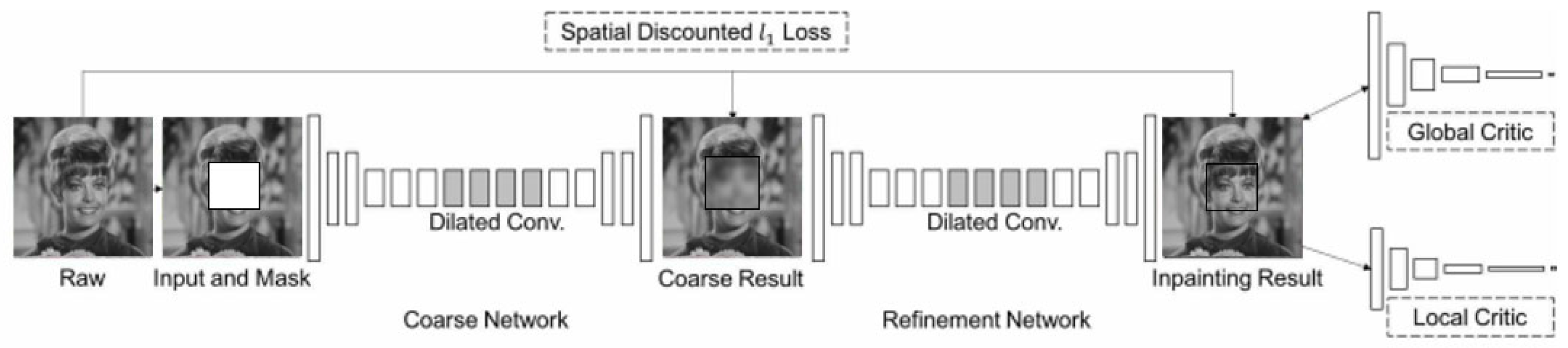
As shown in
Figure 2, their enhanced generative inpainting framework includes two networks: a coarse network and a refinement network. The former is trained in reconstruction loss, and the latter is trained in local and global WGAN-GP adversarial loss and reconstruction loss.
In the coarse network, a straightforward dilated convolutional network is trained with reconstruction loss to fill in the missing data, referred to as foreground, which is initially masked. In contrast, the unmasked portion of an image is termed background. Once the coarse result is obtained, the contextual attention layer is integrated into the refinement network to cooperate with the detailed conventional network. Finally, the inpainting result is obtained. In the contextual attention layer, two operations are included: one is to find features that match the background of the foreground to the background of the surroundings, and the other is attention propagation. During the finding match feature stage, Yu et al. [
19] extracted patches sized 3 × 3 from the background and reshaped them as the conventional filters. The similarity function designed to measure the similarity between foreground patches {
fx,y} and background ones {
bx′,y′} is defined as
where {
fx,y} denotes the foreground patches, {
bx′,y′} denotes the background patches, and
S(x,y),(x′,y′) is the cosine similarity and denotes the similarity between the patches centered in foreground and backgrounds. The second stage involves attention propagation, which is grounded on the observation that a shift occurring in the foreground patch could significantly influence maintaining a similar shift in the background patch. This is because adjacent areas typically preserve the same texture or similar colors. Yu et al. [
19] performed left-to-right propagation from the top-left to the bottom-right in the attention map, using a k-sized matrix as the kernel. Their experimental results confirmed that attention propagation boots either inpainting results in the testing phase or enriches gradients in the training phase.
Based on Yu et al.’s [
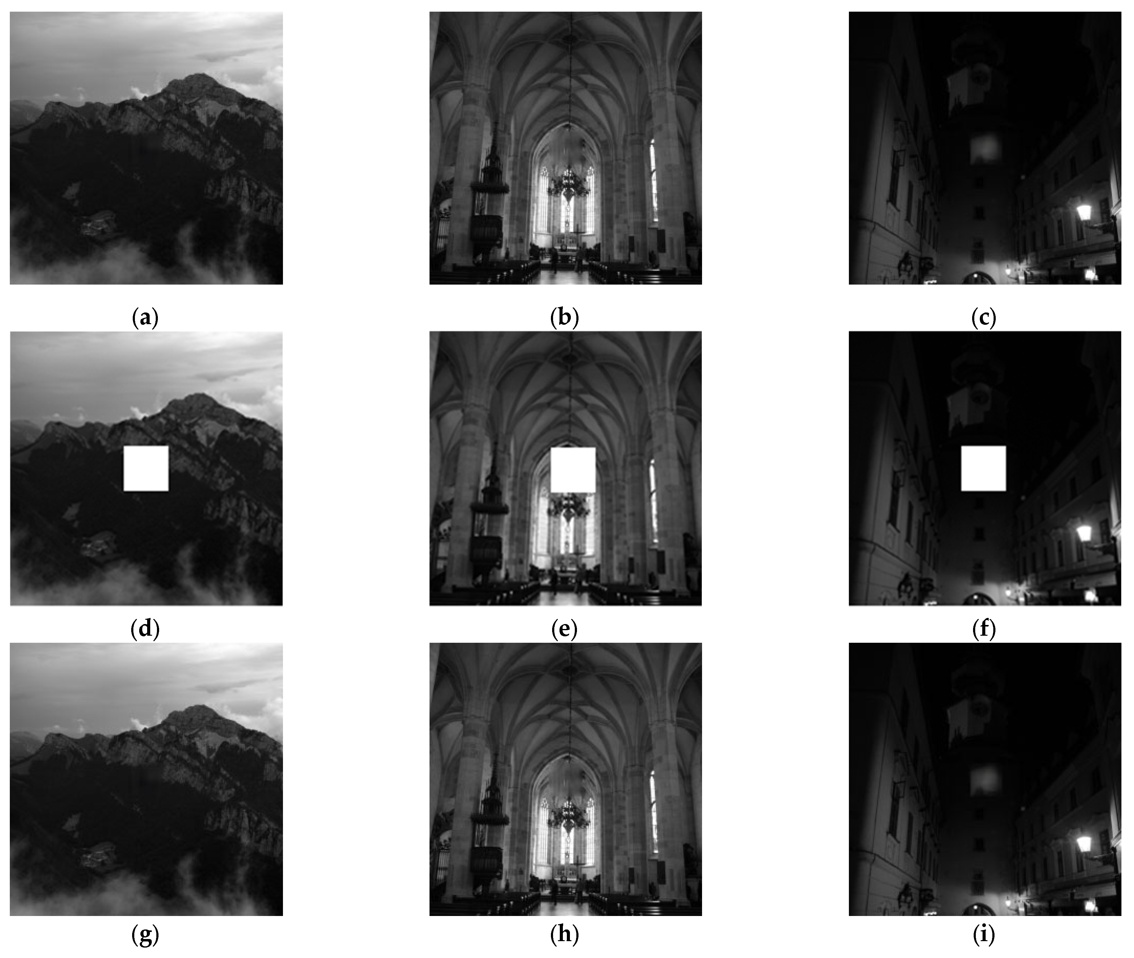
19] model, PSNRs of four selected test images are presented in
Figure 3. The first row presents four raw images with a mask. It is noted the content within the mask is blocked. The second row presents the inpainting results, and the missing content blocked by the mask has been reconstructed by Yu et al.’s [
19] model. The corresponding PSNRs are derived by comparing the original image without mask and the corresponding inpainting result. Notably, the PSNRs of the four test images ranged from 26.45 dB to 54.21 dB. Although the image quality of the inpainting results is diverse it can be found visual quality is still acceptable as shown in
Figure 3.
2.2. Proposed Enhanced Inpainting Scheme
Based on the model architecture of Yu et al.’s [
19] scheme, we propose an enhanced version of the architecture as shown in
Figure 4, aiming to improve further the similarity between the inpainted medical images and the original medical images. In our proposed enhanced model, in addition to maintaining the original method by Yu et al. [
19] with a single coarse network and refinement network, we have added an additional refinement network. The reason is that after processing the refinement network in Yu et al.’s [
19] architecture, some areas still showed inconsistencies in texture repair. Therefore, we hope to refine the initial repair results further to achieve better repair outcomes.
Figure 4a extends the original architecture by taking the results after the first refinement as input for another round of refinement network, and the second one is called an enhancement network. This architecture is used as the generator, which works with the Global Discriminator to form a Generative Adversarial Network.
The coarse network consists of three components: Part-a, responsible for initial feature extraction; Part-b, which employs dilated convolution; and Part-c, which utilizes standard convolution. The part-a stage comprises layers conv1 through conv4. The primary role of conv1 is to extract low-level image features, such as edges and textures. By increasing the number of channels, the ability of conv1 is enhanced and represents the image’s texture. Layers conv2 to conv4 perform down-sampling using a convolutional stride of 2, reducing the feature map size while retaining essential features. These layers also extract higher-level features, enabling the capture of more intricate image structures.
In the part-b stage, layers conv5 and conv6 focus on advanced feature extraction, enabling the feature maps to represent high-level characteristics of the input images. Layers conv7 to conv10 incorporate dilated convolutions, a technique where gaps are introduced within the filters. This approach effectively expands the receptive field without the loss of information typically associated with pooling operations. The receptive field refers to the specific region of input data that influences a neuron in the network. Its size plays a crucial role in determining the network’s ability to interpret and learn from the input data. Smaller receptive fields excel at capturing fine-grained local details, while larger receptive fields are better suited for understanding broader contextual relationships within the image. In the part-c stage, layers conv11 through conv17 are responsible for advanced feature processing, sampling operations, and producing the final output image. Layers conv11 and conv12 focus on extracting additional features while preserving spatial information through relatively small convolutional operations. Subsequently, layers conv13 to conv17, combined with up-sampling techniques such as interpolation, gradually restore the resolution of the feature maps. This step-by-step refinement ultimately leads to the generation of the final output image with enhanced detail and accuracy.
The refinement network is a deep convolutional neural network optimized for generating high-quality images. It comprises convolutional blocks and up/down-sampling operations, commonly applied in tasks such as image restoration and generative adversarial modeling. In the part-a stage, layers conv1 through conv6 are dedicated to extracting low- and mid-level features from the input images. Layers conv2 and conv4 perform down-sampling to reduce the spatial dimensions of the feature maps, while layers conv3, conv5, and conv6 focus on extracting mid-level features. These operations establish a foundation for subsequent contextual attention mechanisms through progressive sampling. In the part-b stage, layers conv7 to conv10 utilize dilated convolutions to expand the receptive field without substantially increasing computational complexity. By leveraging dilated convolutions, these layers enable the model to capture a wider range of contextual information. Layers conv11 and conv12 then refine and integrate the feature maps, enhancing their representational capability before advancing to the next stage.
In the generative adversarial network (GAN) stage, the generator and discriminator are trained adversarially to optimize their performance. The generator strives to create realistic images capable of deceiving the discriminator, while the discriminator works to differentiate between real and generated images accurately. The loss function of the generator combines the L1 loss and the WGAN adversarial loss. Meanwhile, the discriminator’s loss function includes the adversarial loss and a gradient penalty term. The overall GAN loss function integrates the losses from both the generator and the discriminator. The proposed parameters used in the coarse network and the refinement network are presented in
Table 1 and
Table 2, respectively.
3. Proposed Watermarking Scheme
As previously mentioned, there is a strong demand for a visible and user-friendly watermarking scheme in medical applications. “Visible watermarking” refers to the display of a logo representing the original hospital on medical images captured by imaging equipment. “User-friendly watermarking” ensures that once the source or integrity of the medical images is verified, the visible watermark is removed, allowing the doctor to view the clean image for diagnostic purposes. This process helps maintain a high-quality user experience for both the doctor and the patient.
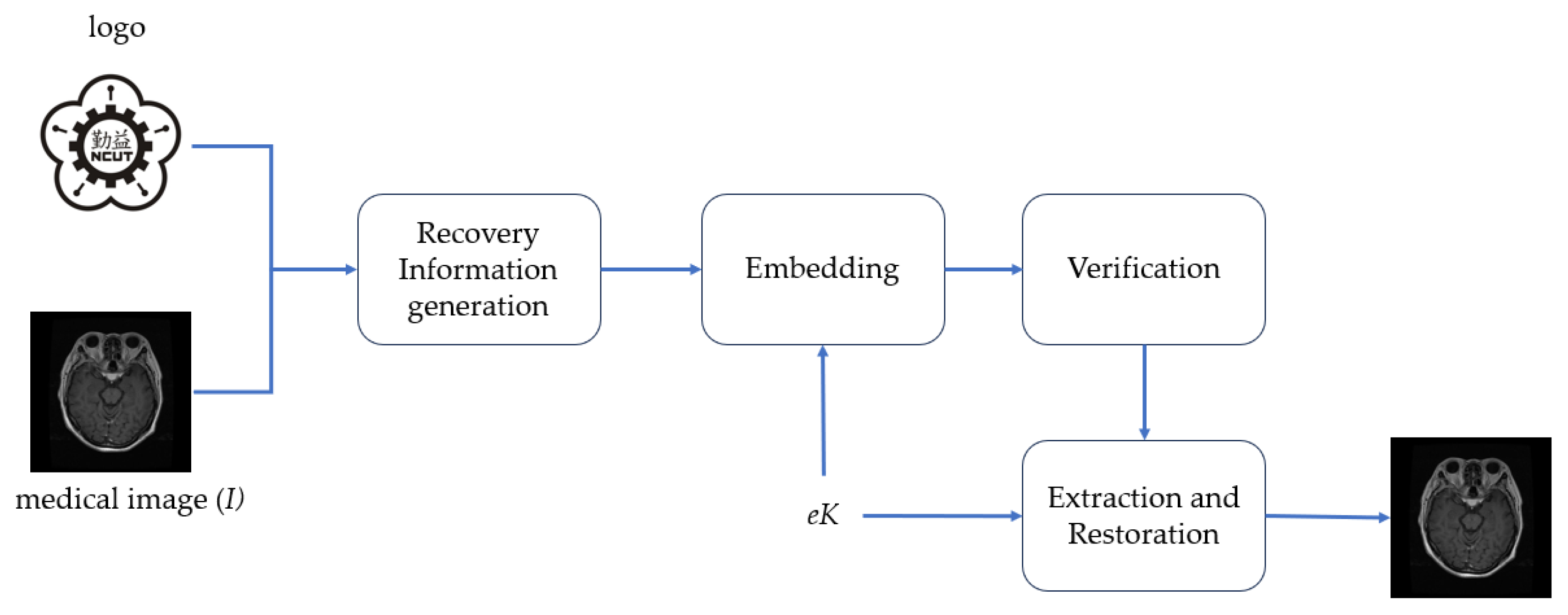
To achieve the above objectives, the framework of our proposed visual and user-friendly medical image watermarking scheme (VUF-MIWS) is presented in
Figure 5. The VUF-MIWS is composed of four phases: recovery information generation, embedding, verification, and watermark removal and restoration. Detailed descriptions of each phase are provided in the following subsections.
3.1. Recovery Information Generation
To ensure the original medical image can be fully restored after watermark verification, the missing information caused by the visible watermark must be collected beforehand and used as recovery information (RI) for the restoration process.
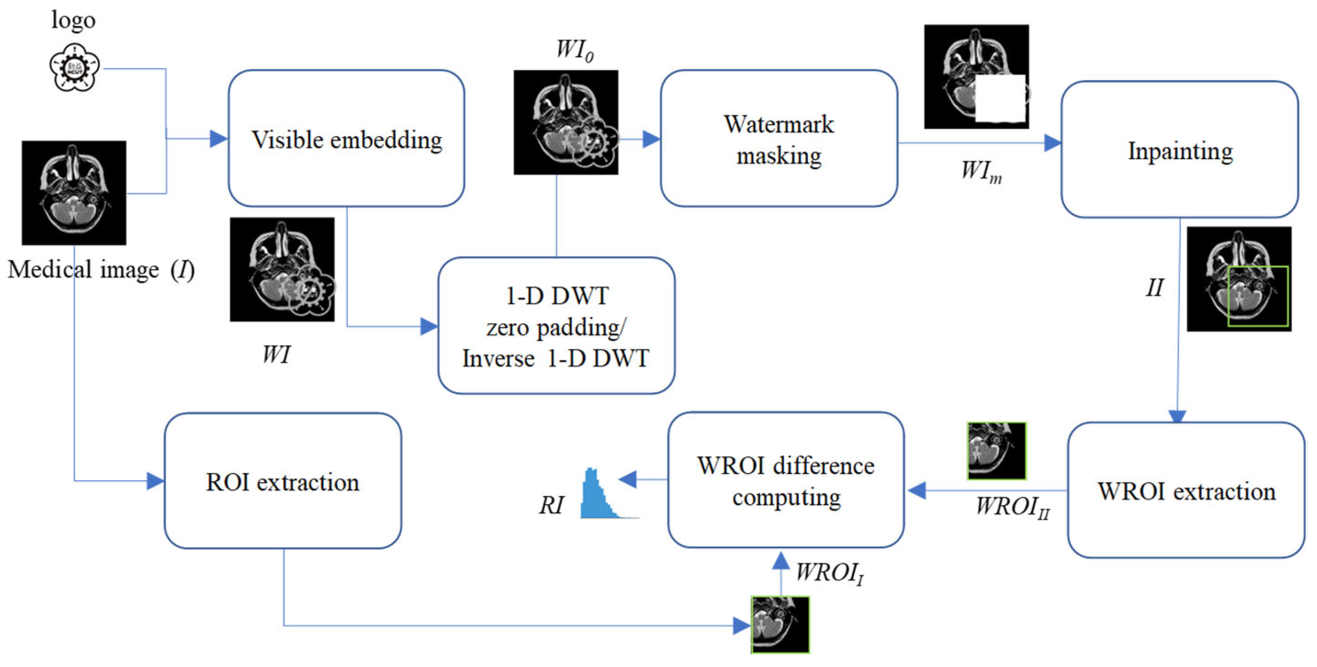
Figure 6 illustrates the seven steps involved in the recovery information generation phase for generating the RI. Detailed descriptions of these steps are provided below.
- Step 1.
Embed the logo into the medical image I by stacking operation or any other visible watermark algorithm, resulting in the generation of a watermarked image WI.
- Step 2.
Perform 1-D DWT on the watermarked image WI.
- Step 3.
Convert coefficients on the LL subband into a binary representation.
- Step 4.
Set the second-to-last bit of the binarized LL coefficients to “0”.
- Step 5.
Perform inverse 1-D DWT to get the zero-padding watermarked image WI0 after zero padding.
- Step 6.
Mask WI0 with a matrix of the same size as the logo to generate the masked medical image WIm.
- Step 7.
Conduct the proposed inpainting operation to generate the reconstructed results for the masked region of WIm.
- Step 8.
Extract the watermark region called WROIII from the inpainting image II.
- Step 9.
Extract the watermark region called WROIII from the original medical image I.
- Step 10.
Compute the difference values between the WROIII and WROII to get the RI for restoration.
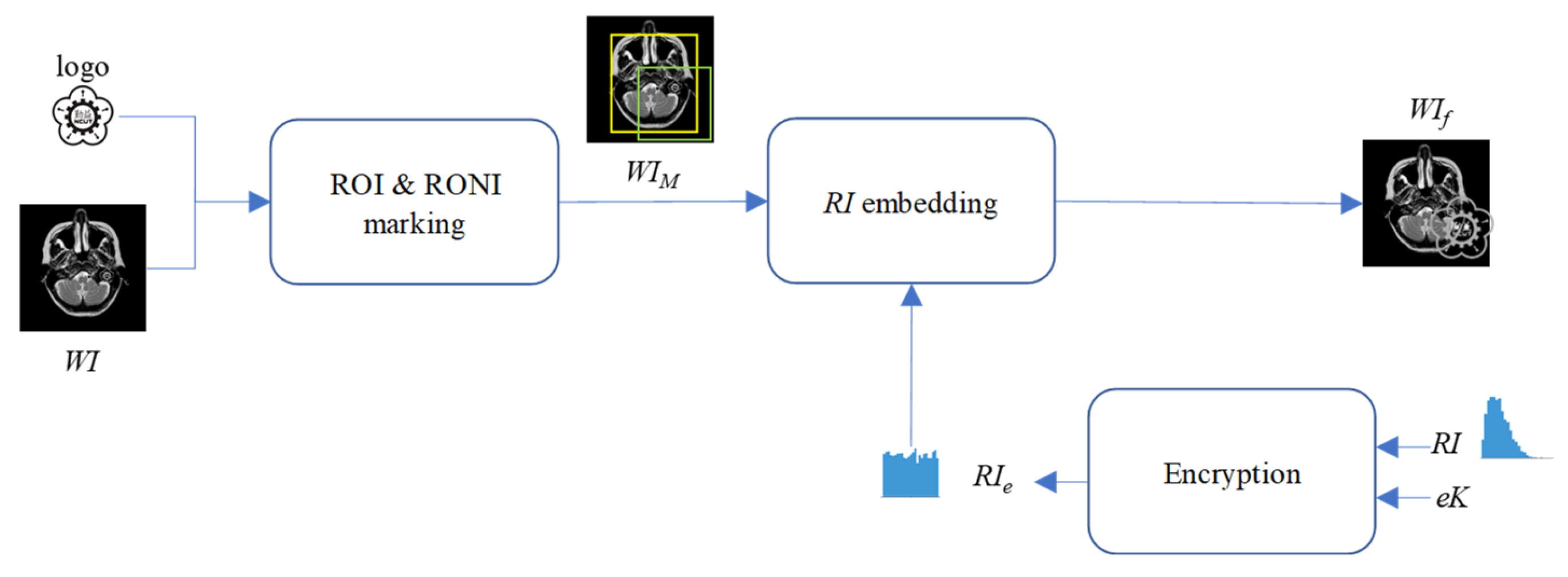
3.2. Embedding
This subsection primarily focuses on embedding the RI to ensure the original medical image can be fully restored after watermark verification. The RI is embedded into the region of non-interest (RONI) of the watermarked medical image WI. The proposed DWT-based RI hiding scheme is shown in
Figure 7. Note that the encryption key
eK can encrypt
RI before hiding it into
WI. The encryption key can be stored in the patient’s health smartcard or in the hospital’s cloud server. In the future, doctors can only download the encryption key from the hospital cloud server once the hospital’s access control system grants them access.
- Step 1.
Mark the ROI and RONI on the watermarked image WI. The ROI is the region critical for the doctor’s diagnosis, and its content must remain undamaged, even after watermarking. The ROI may include part of the visible watermark, meaning the ROI could also be a region of the visible watermark (WROI). The RONI is the area that does not contain either the ROI or the visible watermark, where pixel information can be modified to carry the RI.
- Step 2.
Encrypt the RI. with a pre-shared encryption key eK. To enhance the confidentiality of hidden RI., the symmetric encryption algorithm, Advanced Encryption Standard (AES), is employed with the encryption key eK.
- Step 3.
Perform 1-D DWT on the WI.
- Step 4.
Convert coefficients located at LL subband into a binary representation.
- Step 5.
Convert RIe into a binary representation, denoted as bRIe.
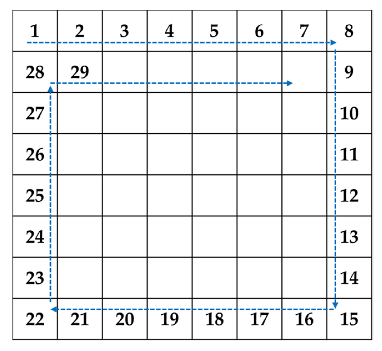
- Step 6.
Decide the circular hiding path as shown in
Figure 8.
- Step 7.
Use LSB substitution to sequentially embed 1-bit of
bRIe into the second-to-last bit of the binary representation of LL coefficients along the concealment path specified in
Figure 8.
- Step 8.
Perform the inverse 1-D DWT on the stego image generated by Step 7 to obtain WIf finally.
3.3. Verification
After embedding RI into WI to obtain WIf, WIf can be shared with the doctor for remote diagnostic consultation. The doctor can use the visible logo embedded in the medical image as a visible watermark to directly assess the reliability and integrity of its source. However, since the region of the watermark (WROI) overlaps with the ROI in the medical image, the doctor requires either the patient’s cooperation and access to the encryption key eK stored in the patient’s health smartcard or permission to download the encryption key eK from the hospital’s cloud server through the hospital’s access control system.
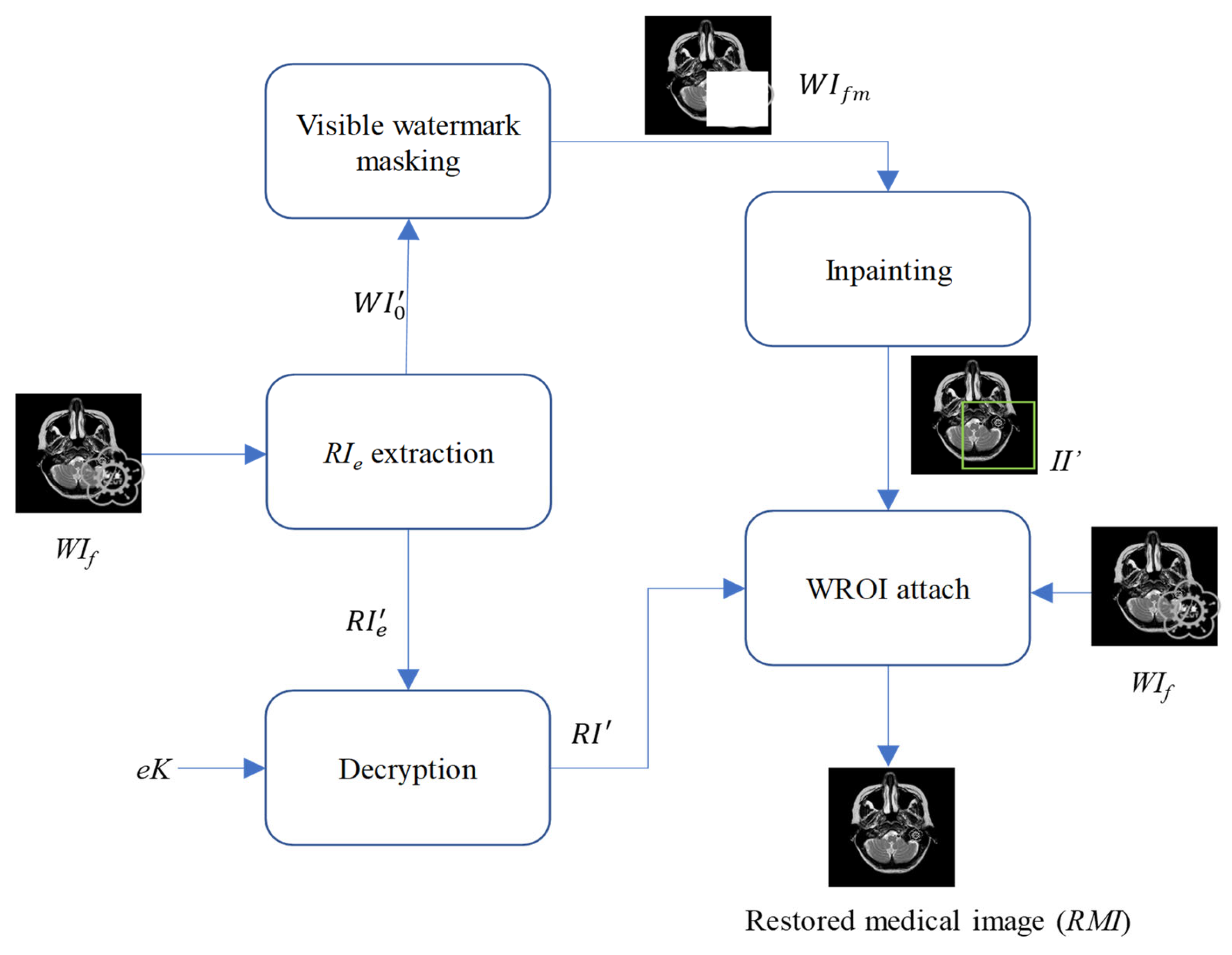
3.4. Watermark Removal and Restoration
After the visible watermark is authenticated, we initiate the watermark removal and restoration phase, as shown in
Figure 9.
- Step 1.
Perform 1-D DWT on the received WIf.
- Step 2.
Read coefficients located at LL subband according to the diagonal pairing hiding path shown in
Figure 8.
- Step 3.
Convert each read coefficient into the binary representation.
- Step 4.
Extract the second-to-last bit from the binary representation of the read coefficient.
- Step 5.
Collect all extracted bits to be the RI’e.
- Step 6.
Convert all LL coefficients into the binary representation.
- Step 7.
Replace all the second-to-last bits of the binarized LL coefficients with “0”.
- Step 8.
Perform the inverse 1-D DWT to get WI′0.
- Step 9.
Decrypt the extracted RI’e with the encryption key eK to get the extracted recovery information RI′.
- Step 10.
Mask the visible watermark on the received WI′0 to obtain the masked image WIfm.
- Step 11.
Use masked image
WIfm as the input to conduct the proposed inpainting operation mentioned in
Section 2.2, and finally get the inpainting result
II′.
- Step 12.
Extract the WROI from II′ and attach WROI to the received watermarked image WIf. Next, add the extracted recovery information RI′ to the pixels of the attached watermark region. Finally, not only the visible watermark is removed but the pixels covered by the visible watermark have been restored.
In other words, the Region of Interest (ROI)—the critical area for a doctor’s diagnosis—can be fully restored and is ready to support accurate medical assessment and treatment.
4. Experimental Results
The experiments were conducted on two systems. The first system ran on Ubuntu 22.04, equipped with an Intel i7-9700KF CPU @ 3.60GHz (8 cores), an Nvidia GeForce RTX 3090 GPU, 32 GB of RAM, and Pytorch (
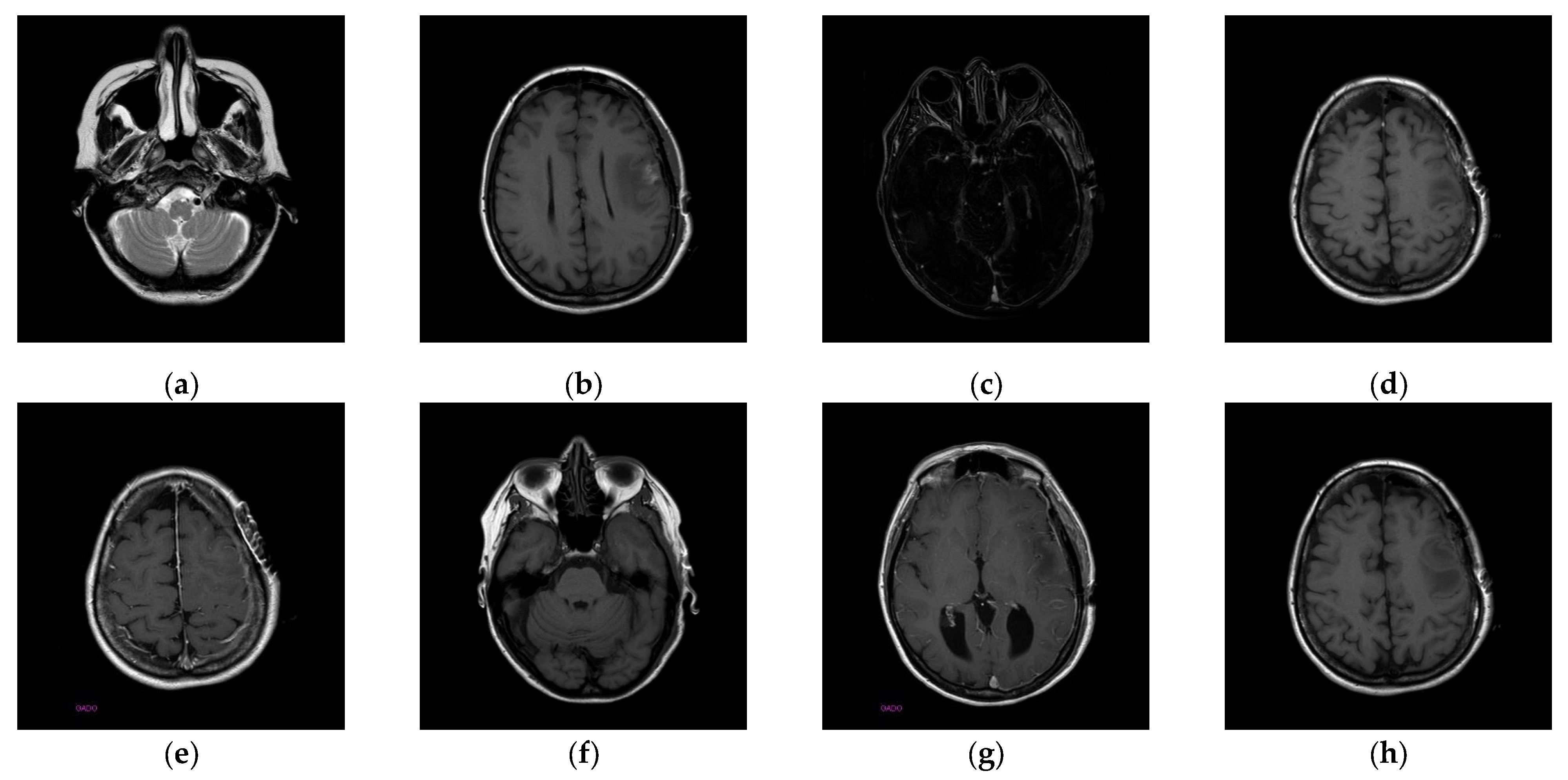
https://pytorch.org/) for the experimentation. The second system, called the Type 1 device, is a notebook with an Intel(R) Core (TM) i7-10510U CPU @1.80 GHz 2.30 GHz, 16.0 GB RAM, 64-bit Windows operation system, and GPU MX 250. The third system, called the Type 2 device, is a notebook with an 11th Gen Intel(R) Core(TM) i5-11400H @ 2.70 GHz 2.69 GHz, 24.0 GB RAM, 64-bit Windows operation system, and GPU Nvidia GeForce 3060. The second system is a notebook that was released around 2019 or early 2020. The third system is also a notebook that was released in early 2021. The two systems were used to simulate resource-constrained environments. Different medical and test images were used as the test images to evaluate the performance of our proposed scheme and to make comparisons between our scheme and Qin et al.’s scheme [
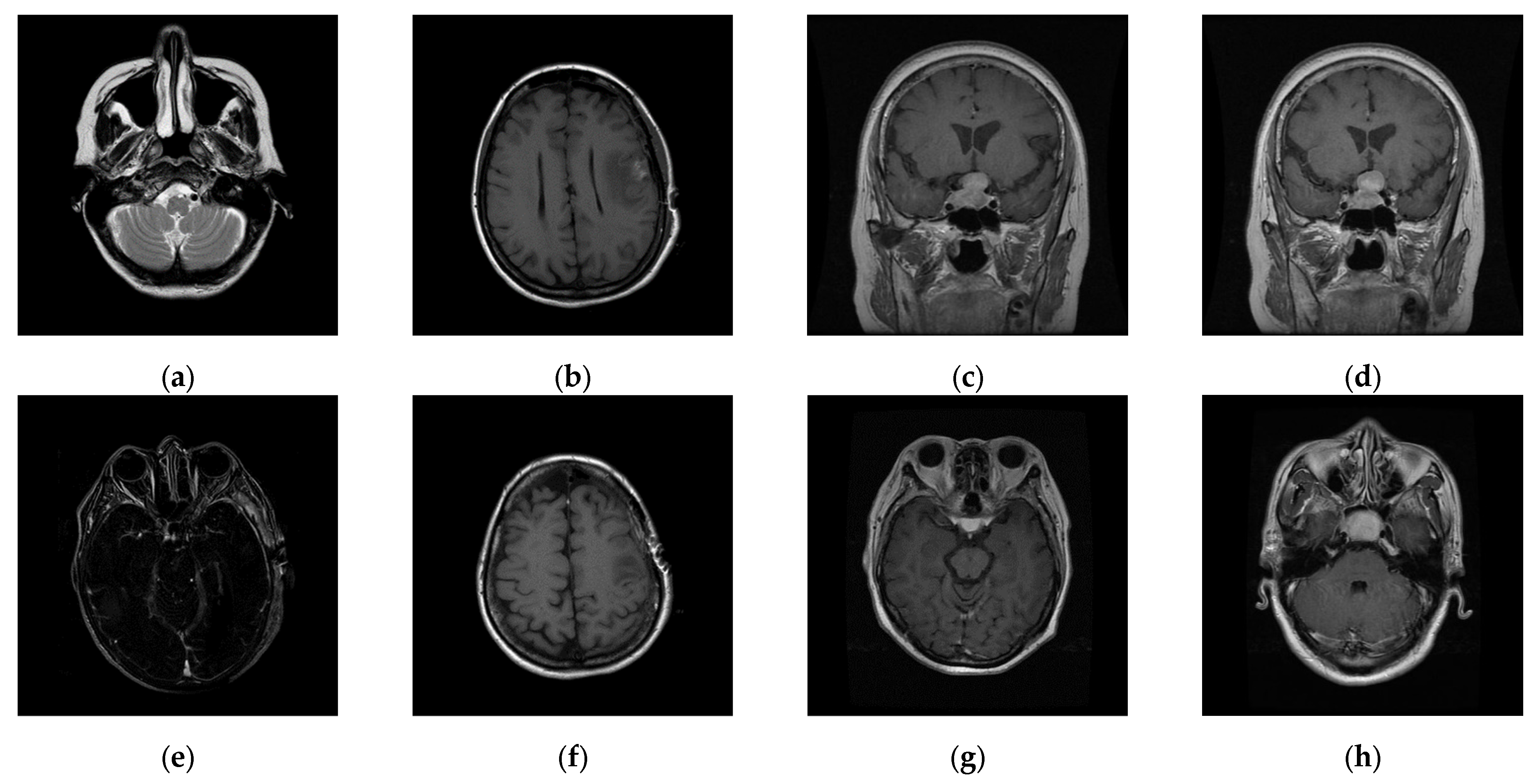
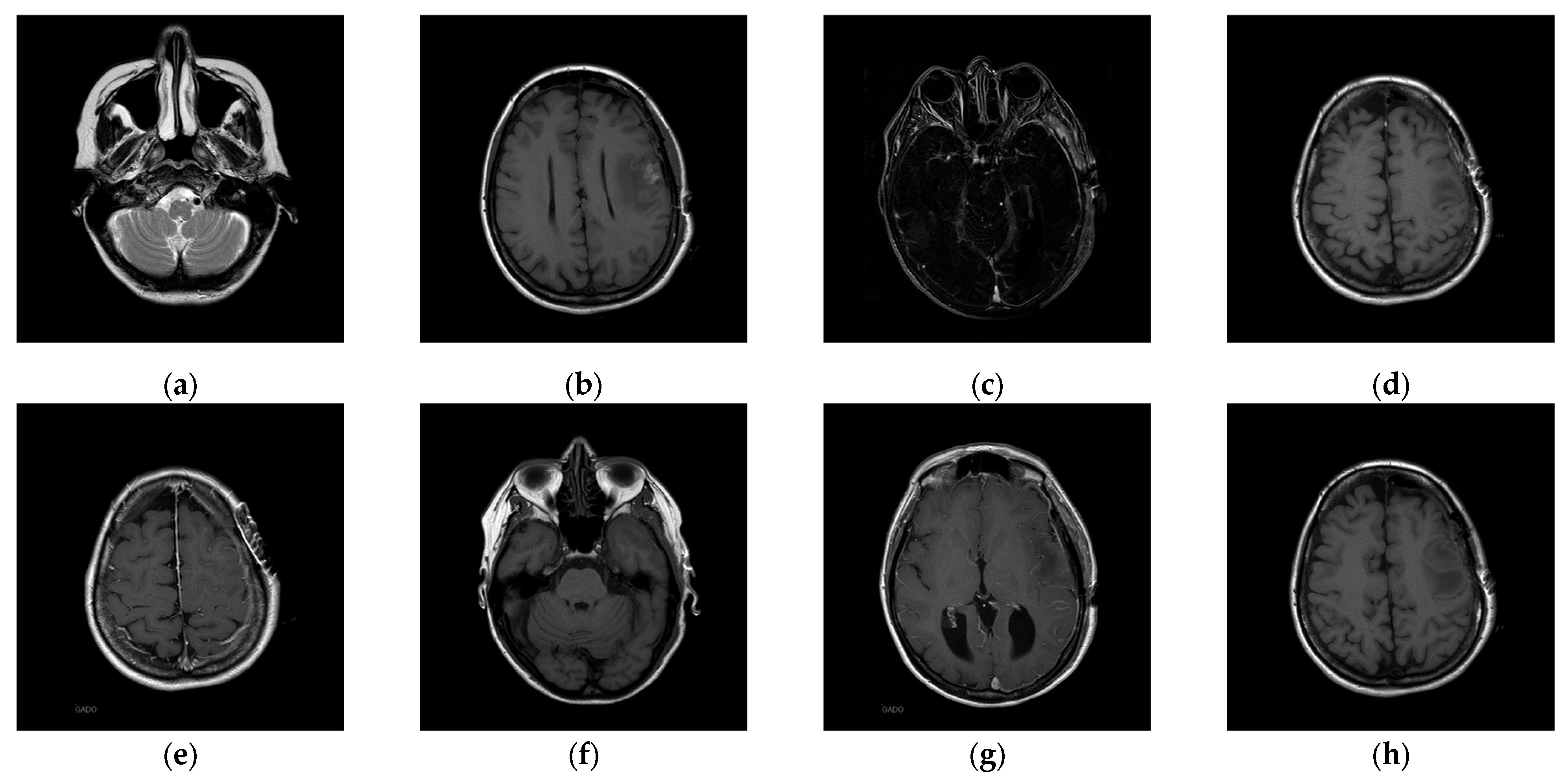
20]. In the first experiment, eight medical images, which are MRI scans of the brain, were randomly selected from the Osirix database [
21] as test images and are presented in
Figure 10 to demonstrate the performance of our proposed scheme in detail. In the second experiment, one hundred medical images, which are also MRI scans of the brain, were randomly selected from the Osirix database [
21] to form Dataset 1 and Dataset 2, as shown in
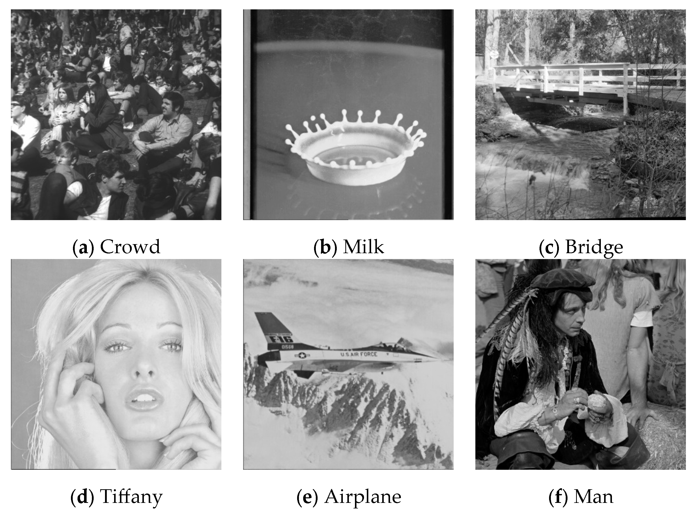
Figure 11, to prove the stable performance of our proposed scheme. In the third experiment, six general grayscale images, sized 512 × 512, demonstrated in
Figure 12, were used to compare with those offered by Qin et al.’s scheme [
20]. The logo depicted in
Figure 13a was used as the watermark for the first and the second experiments and
Figure 13b was used as the watermark for the third experiment.
To better align our VUF-MIWS with the practical needs of clinicians for authenticating medical image sources, we conducted a pilot interview at a regional hospital. In this interview, we defined the critical diagnostic reference area of a medical image as the ROI (Region of Interest) and divided it into nine sub-regions, as shown in
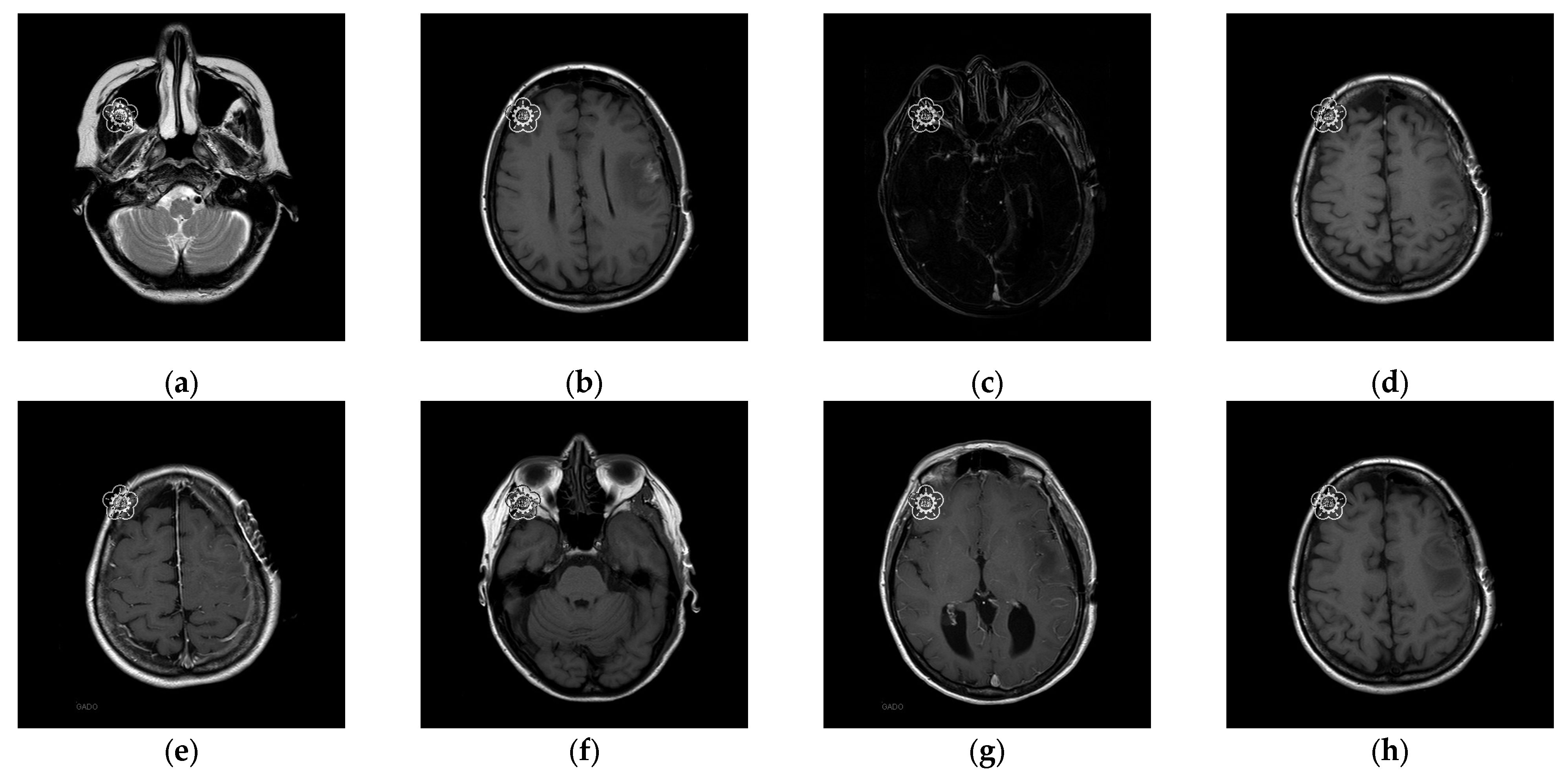
Figure 14. We then asked seven doctors to indicate their two most preferred locations for visible watermarks. Based on the collected feedback, sub-region A received the highest number of votes (a total of nine), followed by sub-regions E and I (both receiving five votes). Therefore, sub-region A was selected as the watermark position for the first and second experiments. The resulting watermarked images for the first experiments are displayed in
Figure 15.
4.1. Performance of the Proposed Scheme
Once the visible watermarked image has been verified, we use the proposed inpainting scheme to remove the visible watermark and restore the original content which contains the completely restored ROI and slightly distorted RONI. The restored images are illustrated in
Figure 16. We can see from
Figure 16 that the restored image appears visually indistinguishable from the original image. To better illustrate the restoration quality, we magnify the restored areas for display, as shown in
Figure 17. We can also observe that the enlarged restored content is visually identical to the original content.
To evaluate the restored image quality, PSNR (peak signal-to-noise ratio) and SSIM (structural similarity index) are used to measure image quality. PSNR is a widely used metric for evaluating the quality of restored images compared to their original versions. It quantifies the ratio between the maximum possible power of image intensity and the power of the noise that affects its representation. The PSNR is defined as
where MSE (mean squared error) is the average squared difference between the pixel values of the original and restored images. In general, a higher PSNR indicates better image quality and lower distortion. When the PSNR exceeds 30 dB, it becomes challenging for the human eye to distinguish between the original and restored images. PSNR is particularly effective when comparing images with similar content, whereas it may not always reflect perceptual quality accurately, especially for images with different visual characteristics.
SSIM is used to measure the perceptual quality of images, focusing on structural information and visual patterns. PSNR only considers pixel-wise differences, while SSIM considers luminance, contrast, and structural information and it is more closely related to human visual perception. In general, SSIM designed to reflect changes in structural information, is defined as:
where
x and
y are two images,
μx and
μy are the average values of
x and
y, respectively,
and
are the variances of
x and
y, respectively, and
σxy is the covariance of
x and
y.
C1 and
C2 are small constants to avoid division by zero. The SSIM value ranges from −1 to 1, where 1 indicates perfect structural similarity between the two images. In other words, SSIM equals 1, indicating the structure of the stego image is the same as that of the original image. Higher SSIM values indicate better perceptual quality, implying that the restored image maintains more significant structural and visual similarity to the original.
Table 3 presents the image quality analysis results: PSNR of the watermarked image comparing the original image and the watermarked image, and PSNR of the restored ROI comparing the restored ROI with the original ROI. Since this is a visible watermarking application, the PSNR of the visible watermarked image is slightly lower, around 28 dB. However, after applying our proposed inpainting method to remove the visible watermark and repair the areas damaged by the visible watermark embedding with the recovery information, the original ROI region can be completely restored, with an SSIM value reaching 1.
Table 3 demonstrates that our proposed scheme can effectively eliminate the visible watermark and restore the original image content. It is noted “∞” indicates the restored ROI is the same as the original ROI.
We also demonstrate the inpainting performance improvements made to the method proposed by Yu et al. [
19]. The test image “16.png” is masked with a 64 × 64 region, and the corresponding inpainting results are presented in
Figure 18. We found that the inpainting results of Yu et al.’s [
19] scheme and the proposed scheme appear visually similar. In the histogram analysis, the original image and the inpainting result of our proposed scheme almost overlap on the histogram. However, in Yu et al.’s [
19] scheme, the original image and the inpainting result show a greater difference in the histogram.
Table 4 compares the inpainting results between the scheme proposed by Yu et al. [
19] and our improved method. Our enhanced scheme achieves a PSNR range of 31.55 dB to 51.13 dB for inpainted images, which is higher than the 29.44 dB to 47.48 dB range of Yu et al.’s [
19] scheme. Additionally, there is a significant difference in SSIM performance.
Table 4 confirms that our enhanced inpainting scheme is more effective at restoring the original image content than Yu et al.’s [
19] scheme, both in terms of PSNR for inpainting and PSNR for WROI inpainting. This improvement is due to the fact that the closer the pixel values of the inpainted image are to the original, the smaller the recovery information becomes. As a result, the distortion caused in the RONI during the embedding of recovery information is significantly reduced.
Based on the experimental results shown in
Table 4, our proposed scheme can effectively assert the copyright of medical images. The proposed visible watermarking scheme makes the watermark visible so that the medical image content is copyrighted or protected, which serves as a deterrent against unauthorized copying or illegal modification during the transmission. After verifying the legitimacy of the medical images, our proposed scheme can successfully remove the visible watermark with our enhanced painting model and later restore the original image content located at ROI with our designed restoration mechanism, which is ready for the doctor’s diagnosis.
4.2. Performance Analysis
To prove the performance reported in
Section 4.1 is stable even when the number of test images is increased and the types of medical images vary, in the second experiment, one hundred medical images randomly selected from the Osirix database [
21] to form Dataset 1 and Dataset 2, as shown in
Figure 11, and were used to evaluate the stability of our performance. Experimental results are listed in
Table 5. It is worth noting that the LSB data hiding strategy is listed alongside our designed DWT-based data hiding strategy in
Table 5 to demonstrate that our proposed VUF-MIWS framework can seamlessly integrate with different data hiding strategies.
Here, the original image refers to the unaltered initial image. The watermarked image represents the image embedded with a visible watermark. The inpainting image denotes the restored version of the watermarked image after the visible watermark has been removed through inpainting. The stego image refers to the inpainting image embedded with recovery information. Finally, the restored image indicates the fully recovered image, reconstructed using the hidden recovery information carried by the stego image. Both data hiding strategies, tested with two datasets containing one hundred test images, ensure that the ROI can be completely restored. Although the RONI of the restored image may exhibit slight differences from the original image due to minor distortions caused by carrying recovery information, the structural integrity of the medical content is preserved, as confirmed by an SSIM value of 1.
The PSNR of the watermarked image and the PSNR of the inpainting image are not influenced by the data hiding strategies. The low image quality, indicated by the PSNR of the watermarked image, confirms that the 64 × 64 visible watermark successfully covers a partial region of the ROI. The average PSNR of the inpainting image, which remains at 42.20 dB across one hundred medical images, confirms the stable performance of our enhanced inpainting method. Furthermore, our proposed VUF-MIWS is designed to assist doctors in visually verifying the authenticity of medical image sources or integrity in the initial stage using the human eye. Once the medical image is authenticated, the visible watermark can be removed through our proposed restoration method. The PSNR of restored WROI and PSNR of restored ROI listed in
Table 5 confirm that our scheme ensures that the critical medical image region (ROI), essential for accurate medical judgment, can be fully restored.
Considering that devices with limited computing resources are often used in medical settings, we simulated a resource-constrained computing environment in the second experiment. This allowed us to evaluate further whether the proposed VUF-MIWS can effectively reconstruct the ROI required for medical diagnosis while maintaining computation performance that meets practical demands. We use two types of laptops with different specifications to simulate the resource-constrained computing environment. Even the Type 1 device deploys a relatively lower computation resource than the Type 2 device; on average, it takes 140 sec to generate an inpainting image.
The visible watermark embedding, including inpainting generation, is always performed on the server side, where computational resources are sufficiently available. Therefore,
Table 6 only presents the computation times required for restoration.
Table 6 shows that the Type 1 device takes between 0.09 s and 0.87 s to restore the image. In contrast, the Type 2 device requires less than 0.34 s to restore the image from the watermarked version when the RAM is up to 24 GB. Experimental results also demonstrate that even in the worst case, our restoration mechanism takes only 0.87 s to restore the medical image. This confirms that our restoration mechanism is both effective and feasible, even in resource-constrained environments at the doctor’s or hospital’s side.
4.3. Comparisons with Qin et al.’s [20] Scheme
In this subsection, we also compare our proposed scheme with Qin et al.’s scheme [
20], which adopts the inpainting approach to achieve the removal of the visible watermark as we did.
Table 7 demonstrates the comparisons between Qin et al.’s [
20] scheme and ours. It is noted that “∞” indicates the ROI is the same as the original ROI.
In Qin et al.’s [
20] scheme, they attempted to reduce the visual impact of the visible watermark by lightening the watermark and minimizing the weight of the watermark’s pixel values when blending with the image content. In contrast, our VUF-MIWS does not lighten the watermark’s pixel values, as our design concept aims to make the verification process easy and user-friendly. The PSNR values of the watermark listed in
Table 7 show that the watermark PSNR in our scheme is relatively lower than that in Qin et al.’s [
20] scheme, confirming that our visible watermark design concept has been effectively implemented.
Regarding the PSNR values of the inpainting, our results are also lower than Qin et al.’s [
20] scheme. This is because our enhanced inpainting model, which was trained on medical images, is directly applied to general images, and the network parameters have not been retained. Even under these conditions, the PSNR values of inpainting from our enhanced model still range from 37.46 dB to 41.07 dB. Finally, the PSNR values of the ROI confirm that both schemes can fully restore the ROI content.
5. Conclusions
This paper introduces a new visible and user-friendly watermarking scheme designed specifically for medical images. Our approach aims to achieve two primary objectives: ensuring the watermark is easily verifiable by doctors while preserving the usability of medical images for high-quality diagnosis and a positive user experience between doctors and patients. To meet these goals, we combine a data hiding strategy with an inpainting technique.
This study is the first work that includes doctors’ opinions for selecting watermark positions when designing a removable-visible watermark for medical images to help doctors authenticate the source of the images they receive. In our VUF-MIWS, we have enhanced Yu et al.’s [
19] scheme to better preserve the texture of medical images, minimizing the difference between the original image and the inpainting result. Both LSB-based data hiding and our designed DWT-based data hiding strategies ensure the full restoration of the ROI (Region of Interest) in medical images. Experiments confirm that both the ROI of the medical image and the watermarked region can be completely restored, which is essential for medical treatment scenarios. Feedback from the doctors interviewed also confirms the key features of our approach: visible authentication, complete restoration of the ROI, and a high SSIM value of 1, which indicates that the structure of the entire image remains unchanged compared to the original.
Although existing watermarking-based medical image studies have not fully addressed ethical concerns or privacy issues, we believe these are critical topics that should be explored in future research. Moving forward, we aim to use our VUF-MIW as a demonstration platform to gather feedback from both doctors and patients, with the goal of identifying areas for improvement and addressing these important concerns. Furthermore, we plan to either incorporate the symmetric structural features of MRI images into our inpainting model to further enhance the quality of the results or extend the application of our proposed scheme to other types of medical images beyond MRI brain scans, thus enhancing its versatility.


