Abstract
This study introduces a groundbreaking antenna system, the directive Metasurface Half-Maxwell Fish-Eye (MHMF) lens antenna, tailored specifically for Internet-of-Things (IoT) networks. Designed to operate at 60 GHz, this antenna ingeniously integrates a dipole antenna within a parallel-plate waveguide to illuminate a Half-Maxwell Fish-Eye (HMFE) lens. The HMFE lens serves as a focal point, enabling a crucial high gain for IoT operations. The integration of metasurface structures facilitates the attainment of the gradient refractive index essential for the lens surface. By employing commercial Ansys HFSS software, extensive numerical simulations were conducted to meticulously refine the design, focusing particularly on optimizing the dimensions of unit cells, notably the modified H-shaped cells within the parallel waveguides housing the beam launchers. A functional prototype of the antenna was constructed using a standard PCB manufacturing process. Rigorous testing in an anechoic chamber confirmed the functionality of these manufactured devices, with the experimental results closely aligning with the simulated findings. Far-field measurements have further confirmed the effectiveness of the antenna, establishing it as a high-gain antenna solution suitable for IoT applications. Specifically, it operates effectively within the 60 GHz range of the electromagnetic spectrum, which is crucial for ensuring reliable communication in IoT devices. The directive HMFE lens antenna represents a significant advancement in enhancing IoT connectivity and capabilities. Leveraging innovative design concepts and metasurface technology, it heralds a new era of adaptable and efficient IoT systems.
1. Introduction
The engineering of advanced microwave lens technologies relies heavily on gradient refractive index (GRIN) media [1,2,3,4,5,6,7,8,9], which allow for precise control of the refractive index [9,10,11,12,13,14,15,16,17,18,19], and the manipulation of electromagnetic waves across various frequencies. This sophisticated control allows for the fabrication of intricate systems and devices, such as invisibility cloaks [1], Fresnel lenses [2,3], metamaterial transmit arrays [2], Maxwell Fish-Eye lenses [5,6,7], GRIN lenses [7,8,9], Luneburg lenses [11,12,13,14,15,16,17,18,19], and beam-shaping lens antennas [9]. Luneburg and Half-Maxwell Fish-Eye lenses have a crucial role in the advancement of modern optical and electromagnetic technologies, as demonstrated by the strategic application of GRIN lenses in these areas [6]. To create GRIN lenses [2], two main approaches are used. The first method makes use of a completely dielectric structure [2], with concentric dielectric rings used to adjust the refractive index in certain areas for the best possible control of the flow of electromagnetic waves [2,3].
Second, a printed circuit board (PCB) with a metallic periodic structure is used as a planar medium in the second method to provide the intended platform to direct the light or electromagnetic wave flow [5,6,7]. For some uses, such as Fresnel [3], Luneburg [4,11,12,13,14,15,16,17,18,19,20], or Maxwell Fish-Eye lenses [5,6,7], this arrangement works well to achieve the required refractive indices. A major improvement in Internet-of-Things (IoT) [10] is the incorporation of GRIN media into microwave lens technology [1,2,3,4,5,6,7,8,9]. For IoT applications to work [10], the transmission and processing of signals must be highly developed to guarantee the smooth interaction of the many interconnected devices. Internet-of-Things devices equipped with GRIN lenses can significantly enhance the accuracy and efficiency of electromagnetic wave propagation [4,11,12,13,14,15,16,17,18,19,20,21,22,23,24,25,26,27,28]. Improving connectivity, reducing signal interference, and increasing the operational range of IoT networks are all critically important goals that must be pursued [10]. More than that, GRIN lens technology used in the IoT networks can lead to the development of devices that enhance integration, performance, and compactness. To illustrate this, IoT communication networks can be made more effective with antennas that use GRIN lenses [1,2], which increase gain and directivity. Furthermore, by utilizing GRIN technology to deploy metamaterial lens structures, signal strength and quality can be greatly enhanced, guaranteeing dependable and strong connectivity amongst IoT systems [10].
In this study, a new millimeter-wave antenna design is presented based on a Half-Maxwell Fish-Eye (HMFE) lens with multiple dipole feeds for beam-switching [5,6,7]. When subjected to end-fire radiation in the 57–64 GHz band, this antenna shows high gain and directive patterns [3]. Because of its passive beamforming approach, the design is simple and efficient, making it ideal for IoT applications [10]. To achieve the desired refractive index [2], the antenna uses metamaterial cells, also known as meta-atoms, which can have their dimensions adjusted. This arrangement allows for the utilization of dipole antennas to evenly illuminate the surface of the lens, which is essentially encased between two parallel plates. This innovative design has the capability to generate six different beam scanning angles through a straightforward mechanism involving the movement of the beam source. The angles range from −37 degrees to +37 degrees, with increments at −19, 0, and +19 degrees. To simplify passive switching with a high-gain output, each dipole antenna shines its own radiation on the Maxwell lens’s surface, redirecting the beam in the opposite direction. Throughout this study, various antenna models suitable for millimeter-wave uses are examined, such as Maxwell lenses [5,6,7], Luneburg lenses [4,11,12,13,14,15,16,17,18,19,20], methods for lens feeding and generating refractive indices [4,11,12,13,14,15,16,17,18,19,20,21,22,23,24,25,26,27,28,29,30,31], and configurations of array antennas [4,14,15,16,17,18,19,20,21,22,23,24,25,26,27,28,29,30,31]. The outcomes from these references have been utilized to enhance the development of this prototype [32,33,34,35,36,37,38,39,40].
In summary, this paper is organized in a way that explains how the Half-Maxwell Fish-Eye (HMFE) lens works, and then how the metamaterial unit cell (H-shaped) contributes to the Maxwell Fish-Eye lens’s desired refractive index. What then follows is a description of a Maxwell Fish-Eye lens prototype, a discussion of possible defocusing problems, and an analysis of the step-by-step designing of the lens mechanism. Careful measurements of the radiation patterns and gain performance of this prototype showed that across the whole 57–64 GHz frequency band, the antenna had a radiation efficiency of 37% and a gain of more than 15 dBi. The results of this study pave the way for future improvements in the IoT communications infrastructure by demonstrating the feasibility of incorporating sophisticated beam-switching capabilities into small and efficient designs.
2. Cell Design for the Simulation of Virtual Permittivity and Refractive Indices
In the field of virtual refractive index design, there are two principal approaches to consider [2,3]. The first involves the use of cells in a free-standing arrangement [2], while the second employs cells integrated within a waveguide configuration. Metamaterial cells [2], especially those constructed into specific configurations such as “H-shaped” structures [5,6,7], are engineered to display distinctive electromagnetic attributes that are absent in naturally occurring materials [6,31,32,33,34,35]. These unique properties include a negative permittivity and refractive indices, which open possibilities for advanced wave manipulation techniques, including cloaking, superlensing, and negative refraction [32,33]. Exploring the impact of different setups on these metamaterial cells—whether they are free-standing [3] or encapsulated between parallel waveguides [2]—is critical for understanding their effectiveness, particularly in relation to their virtual permittivity and refractive indices [2]. We will now examine the pros, cons, and limitations of each scenario.
In a free-standing configuration [3], the metamaterial’s interaction with electromagnetic fields can exhibit a broader range of behaviors due to the absence of confinement [31,32,33,34]. However, this increased flexibility may result in less pronounced negative properties as there are fewer interactions with electromagnetic waves [2], making precise control over the refractive index range more challenging [3]. On the contrary, in setups where cells are enclosed between parallel waveguides [5,6,7], particularly in quasi-TEM modes [5,6], the metamaterials are placed within a controlled electromagnetic environment. This confinement tends to enhance the material’s interaction with electromagnetic waves [2], potentially leading to more distinct refractive indices. Nevertheless, the specific outcomes are heavily influenced by the characteristics of the waveguides [2], the frequency spectrum, and the detailed arrangement of the metamaterial cells [3], especially concerning wave incidence within the structure [5,6,32].
The choice between these two methodologies hinges on the specific demands of the application, including considerations like lens beamforming [2], precise focusing [3,5,6,7,11], and the creation of lenses with geometric profiles such as Luneburg and Maxwell fish-eye lenses. The refractive index distributions of both the Luneburg lens and the Half-Maxwell Fish-Eye lens in Figure 1 showcase the variation in the refractive index from the center to the edge of each lens. In Figure 2, the refractive index gradients of the Half-Maxwell Fish-Eye lens are juxtaposed through graphical representations, elucidating the change in the refractive index from the lens core to its periphery. Moreover, this figure illustrates the discretization of the lens into square cells, underscoring its effectiveness as a focused lens play form [5,6,7]. Numerous factors come into play during the decision-making process, such as the electromagnetic characteristics sought for the lens and practical concerns related to fabrication complexity and the susceptibility to environmental influences. Given the intricate design, which entails over 400 cells and the requirement to achieve a broad spectrum of refractive indices ranging from two down to one for HMFE lens engineering [5,6,7], it is argued that adopting the second strategy, especially in high-frequency scenarios, represents the more feasible option to meet the designated design criteria. This approach is preferred due to its potential to fulfill the design’s rigorous demands more accurately [2,3], leveraging the controlled electromagnetic environment provided by waveguide encapsulation to achieve the precise refractive index modulation essential for HMFE lens functionality [5,7].
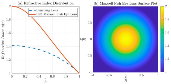
Figure 1.
(a) A plot of the contrasts between the refractive index distributions of the Luneburg lens and the Half-Maxwell Fish-Eye lens, illustrating the change in the refractive index from the center to the periphery of each lens. (b) A surface plot visualization of the refractive index distribution over the surface of the Half-Maxwell Fish-Eye lens [2,5,6,7].

Figure 2.
A comparison of the refractive index gradients of the Half-Maxwell Fish-Eye lens through graphical representations, highlighting the variation in the refractive index from the core to the outer edge of the lens.
The proposed realization of a GRIN lens unit-cell structure integrates a waveguide-enclosed version of modified H-shaped cells [5,6,7,32,33,34], augmented by the inclusion of a rectangular stub. The proposed GRIM unit cell’s geometric configuration is shown in Figure 3. A photograph of the fully constructed MHMF lens is shown in Figure 4. This addition is tailored to finely adjust the refractive index within a specific region across a designated frequency range, particularly within the V-band frequency [2,32]. The dimensions of the rectangular stub incorporated into the H-shaped cells (length and width of the stub) play a pivotal role in determining the medium’s refractive index over this frequency range to achieve the desired lens profile [5,6,7]. This specific structure was chosen for its excellent compatibility with antenna substrates [34], enabling smooth integration without requiring modifications to the antenna’s design profile. For designing the cells within this setup, commercial electromagnetic simulation tools like open-source code or Ansys HFSS [41] can be utilized. In this case, Ansys HFSS was employed to conduct a parametric analysis, aiming to attain the desired refractive index profile effectively [41]. The substrate material selected was Rogers 5880 [42], sourced from the Rogers Corporation’s database, with a thickness of 0.254 mm, a permittivity () of 2.20, and a loss tangent of 0.0009 [42]. This material was opted for due to its low loss properties [34,42].
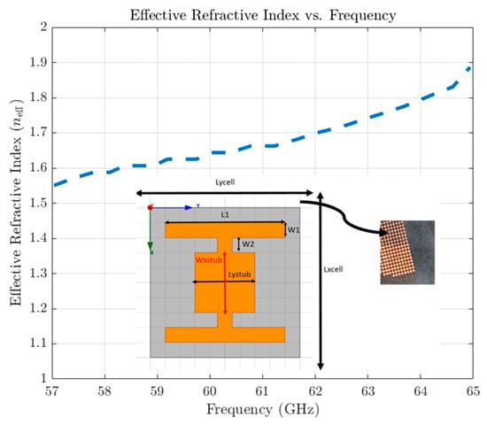
Figure 3.
The proposed GRIM unit cell’s geometric configuration, situated atop a dielectric base. The cell is established on a Rogers RT5880 substrate characterized by a 0.254 mm thickness, a permittivity of 2.3, and a loss tangent of 0.0009. Shown is a detailed view of specified zones featuring designated cells and the effective index of the H-shaped cell configuration, where the dimensions (in mm) are as follows: L1 = 0.61, W2 = 0.08, W1 = 0.073, Wxstub = 0.21, and Lystub = 0.34 [5,6,7,32,33,34].

Figure 4.
A photograph of the fully constructed Metasurface Half-Maxwell Fish-Eye (MHMF) lens, printed on Roger 5880 [42]; the X-axis represents the direction of radiation emitted by the dipole antenna within the structure, aimed toward feeding the lens surface.
3. Metasurface Half-Maxwell Fish-Eye (MHMF) Lens Concept and Mechanism
By applying GRIN principles [11,12,13,14,15,16,17,18,19], we have investigated innovative approaches to refining lens design frameworks focused on enhancing their efficacy [2]. By manipulating the virtual permittivity through metamaterial cells [2,3,5,6,7], lens devices with a range of electrical characteristics can be carefully engineered. Within GRIN lens applications [21,28,29,30,31], integrating customized metamaterial cells presents an exciting departure from traditional dielectric lenses [31,32,33], providing precise control over the permittivity across the lens structure. Recent explorations of GRIN lens advancements, such as the Half-Maxwell Fish-Eye lens [5,6,7] and the Luneburg lens [4,19,20,21,22,23,24,25,26], involve intricate adjustments of the permittivity effects across multi-dimensional configurations.
These studies leverage the unique properties of metamaterial cells to cater to specific focusing requirements [2]. The Half-Maxwell lens [5,6,7], which epitomizes the essence of GRIN optical devices, stands out as a prime example. It demonstrates remarkable enhancements in antenna gain [2,32] and beam shaping [9] within the microwave and millimeter-wave spectrum [3]. Characterized by a radial decline in refractive indices adhering to the range of 1 ≤ n(r) ≤ √2 [2,3], the Half-Maxwell lens exemplifies the successful implementation of GRIN principles to optimize optical performance [5,6,7].
Employing the concept of a spherically symmetric gradient index (GRIN) medium [4,10,11,12,13,14,15,16,17,18,19,20,21], the Half-Maxwell Fish-Eye (HMFE) lens operates within the optical spectrum. Unlike the Luneburg lens [2,22,23,24,25,26], which relies on various wave launchers such as coaxial-to-waveguide launchers, horn antennas [31], hybrid feeds [28], and microstrip beam launchers [5,6,7], the HMFE lens adopts a more compact configuration. Recent studies have explored innovative combinations of wave launchers [5,6,7], like microstrip lines coupled with metamaterial cell designs [28], to effectively manipulate the permittivity of each subzone. The design process of GRIN devices [11,12,13,14,15,16,17,18,19], including the HMFE lens [5,6,7], adheres to the effective medium theory, employing porosity-based, metamaterial-based [5,6,7], and metasurface-based approaches for permittivity control. For precise analysis, this methodology employs periodic porous unit cells, typically with diameters approximately one-tenth of the wavelength. Designers adeptly manipulate the dielectric permittivity by combining theoretical insights with empirical evidence, enabling tailored adjustments to the various subzones comprising the HMFE lens [5,6,7].
Contrasted with the Luneburg lens, the HMFE lens exhibits several advantages. Firstly, its design leads to a more compact structure, diminishing the need for the larger antennas typically required by the Luneburg lens, as demonstrated by the difference in the refractive index profiles in Figure 1. Moreover, the HMFE lens configuration enables more effective management of the virtual permittivity within individual subzones, leading to improved focusing capabilities and enhanced optical performance. This refined design process [5,6,7], guided by effective medium theory and the integration of metamaterial cells [5], empowers designers to make precise adjustments tailored to specific application needs [2,4,5,6,7,10,11,12,13,16,17,18,19,20,21,22].
Presented here is an enhanced version of the printed planar metamaterial GRIN lens antenna, featuring a PCB-based four-layer lens within a parallel-plate waveguide (k), accompanied by a planar dipole feeding platform optimized for 60 GHz applications. These printed sandwiched HMFE lenses are illuminated by a dipole antenna [5], producing a cos10-like pattern that serves as the lens illuminator [2,3]. Consisting of three primary components-printed lenses, dipole antennas [2], and parallel-plate waveguides—the lens antenna achieves meticulous control over the permittivity within modified H-shaped metamaterial cells. Following a comprehensive analytical evaluation of lens parameters, PCB technology is employed during fabrication. As depicted in Figure 5, the H-shaped resonators are etched onto the copper cladding of a 0.4 mm thick Rogers 5880 substrate. In our experiments, the metamaterial planar slab is located within a quasi-transverse electromagnetic (TEM) waveguide, comprising two parallel aluminum plates with dimensions of L = 90 mm, W = 60 mm, and DLens diameter = 62 mm. “The printed HMFE is sandwiched between Rohacell foam spacers at both the top and bottom, which have a permittivity similar to that of air.” The printed HMFE is sandwiched between Rohacell foam spacers at both the top and bottom, which have a permittivity similar to that of air.
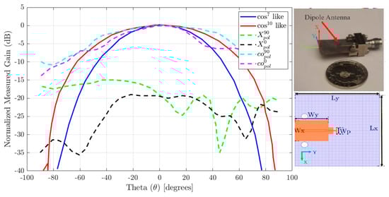
Figure 5.
A single-element lens illuminator along with comparative radiation patterns generated by the beam-launching device, both with and without the inclusion of the perforated lens and parallel plates. It emphasizes a cos10-like pattern specifically at 60 GHz, as detailed in [2,3]. The dimensions of the proposed beam-launching apparatus are Lx = 24 mm, Ly = 24 mm, Wx = 7 mm, Wy = 9.8 mm, and Wp = 2.2 mm. Embedded in the plot is a photograph of the dipole antenna which was fabricated on Roger 5880.
4. Design Approach and Framework
In our study, we created a flat-gradient refractive index framework by employing metamaterial cells [2,5,6,7], intricately engineered for electrical efficiency. This innovative approach resulted in an HMFE [2,5,6,7] lens capable of seamless operation within the 54–64 GHz frequency spectrum, utilizing a specialized configuration of sandwiched H-shaped metamaterial units. The desired gradient index profile of the lens was carefully achieved via a comprehensive arrangement of two-dimensional waveguide assemblies housing the H-shaped metamaterial cells [5,32,33,34]. Emphasis was placed on amalgamating a planar launcher specifically tailored for transverse magnetic (TM) polarized waves, coupled with a printed circuit board dipole antenna serving as the lens’s feed mechanism within a parallel-plate waveguide setup [2,5]. Moreover, the utilization of a planar feed mechanism within the compact lens structure not only ensures optimal integration with the spherical focal points but also streamlines compatibility with RF communication systems, enhancing overall performance and adaptability for IoT devices [10]. Furthermore, the 3D structure serving as an antenna device has undergone careful fine-tuning using a full-wave numerical electromagnetic simulation tool, specifically Ansys HFSS [41], with a specific focus on 60 GHz operation. We recommend employing an HMFE lens model that integrates this methodology [2,5,6,7]. The sequential steps for implementing the design methodology to realize the Half-Maxwell Fish-Eye lens are as follows:
Step 1 initiates with creating a virtual permittivity, a pivotal procedure for engendering a refractive index gradient. This intricately devised method simulates the required optical density variations within the lens material, furnishing precise manipulation over the trajectory and velocity of light as it permeates the lens. Such a technique is paramount for fabricating the specific refractive index gradient vital for the lens’s capability to accurately focus and guide electromagnetic waves.
Figure 1 and Figure 2 vividly illustrate the refractive index contour of a Half-Maxwell Fish-Eye lens [5,6,7] and its segmentation into square units. These figures provide clear insights into two key aspects of optical lens design and examination. Figure 1 depicts and charts the radial refractive index gradient of a Half-Maxwell Fish-Eye lens. Noted for its distinctive refractive index variation, the lens ideally facilitates impeccable focusing and imaging due to its spherical symmetry. The refractive index n(r) modulates with the radius r from the lens’s center, a characteristic prominently displayed in both figures and highlighted with a rainbow color bar to denote distinct zones [2].
In applications where the lens incorporates metamaterial printed cells aligned along the lens direction, it is necessary to discretize the lens diaphragm into the specified cell dimensions. The refractive index profile for the Half-Maxwell Fish-Eye lens [5,6,7] is defined by the equation , where signifies the peak refractive index at the lens’s center, and denotes the lens’s radius [5,6,7]. In this design, is equal to 2 and the lens’s radius is fixed at 31 mm. Such segmentation proves vital for simulations and analyses across various optical design platforms, enabling the lens’s behavior to be approximated in a computationally efficient manner. The process involves partitioning the lens into a matrix of squares and ascertaining the refractive index for each segment [2].
Figure 6 depicts a comprehensive schematic workflow that outlines the sequential process, starting from the generation of a virtual permittivity and culminating in the accurate segmentation of a Half-Maxwell Fish-Eye lens for thorough computational analysis. This detailed sequence highlights the important steps in creating a refractive index gradient [3], which includes first creating a virtual permittivity that is customized to mimic specific variations in optical density within the lens material [5]. This diagram provides a detailed overview of the complex process involved in conceptualizing, designing, and simulating advanced optical lenses.
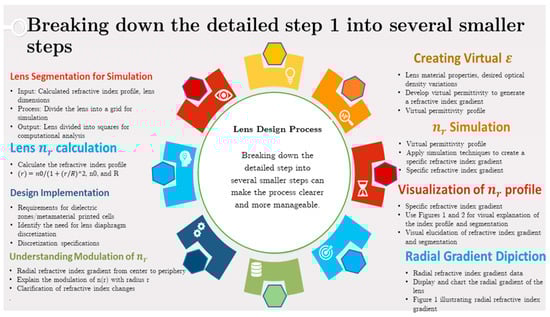
Figure 6.
A schematic workflow illustrating the progression from virtual permittivity creation through to the segmentation of a Half-Maxwell Fish-Eye lens for computational analysis. This sequence highlights the critical steps in generating a refractive index gradient, visualizing the refractive index profile, and preparing the lens design for simulation and practical implementation for step 1.
Step 2 focuses on the meticulous design and simulation of the cellular structure, aiming to align it with the specific direction of the incoming wave. For this purpose, simulation tools such as Ansys HFSS are employed [41], which can conduct in-depth full-wave numerical electromagnetic simulations. These simulations are carefully tailored for optimal performance at the desired frequency specifically for this lens using Ansys HFSS [41]. This process is versatile and can be extended to accommodate the design requirements of any type of lens [2,3,4,5,6,7,8,9,10,11,12,13,14,15,16,17,18,19]. In our quest to fine-tune the refractive index, we utilize modified H-shaped cells strategically sandwiched between waveguides [21,23,24,25,26,27,28,29,30,31,32,33,34]. By varying the thickness of these H-shaped cells [32], we can precisely calibrate the dimensions required for achieving the target virtual permittivity within each cell. The orientation of the incident wave or beam launcher [3] is crucial in feeding the metamaterial cells, significantly influencing the design process, and contributing to the development of the final prototype and the realization of the ultimate gradient index (GRIN) lens structure. In our design, modified H-shaped cells with an added stub enclosed between aluminum waveguides play a pivotal role [2]. Therefore, achieving the desired virtual permittivity and refractive index [3] requires careful consideration of the configuration of these waveguides in our single-cell simulations [7,18,19].
To bridge the gap between the aluminum plates [5,6,7], we employ spacers made from Rohacell foam [43], known for its low permittivity (with a value of 1 at 60 GHz). The selection of this material enables the dipole antenna to be effectively suspended in the air, facilitating a clear passage for the transmission of electromagnetic waves through the structured design. Additionally, the minimal thickness of the GRIN lens necessitates the use of this foam to maintain the lens’s alignment between parallel waveguides.
Step 3 entails the evaluation and documentation of cell dimensions following the simulations, specifically tailored to achieve the desired refractive index profile for the HMFE lens. This process results in identifying the precise dimensions of cells capable of yielding a refractive index range. These critical specifications are cataloged in a database, ensuring that each cell size corresponding to the desired refractive indices is systematically recorded and accessible for future reference and application in the construction of the HMFE lens [7,18,19].
Step 4 begins with creating a comprehensive graphical representation of the Half-Maxwell Fish-Eye lens diaphragm in MATLAB R2017 [44], with the goal of precisely defining its contour according to a predetermined radius. This visualization is crucial for understanding the lens’s geometric dimensions and ensuring adherence to the design specifications. Each cubic cell is precisely dimensioned to 0.8 × 0.75 × 0.254 mm3, crafted according to Aperture Pixel Modeling principles. This approach, executed in MATLAB [44], allows the lens layout to be segmented into discrete cells. These cells are then accurately positioned using the HFSS MATLAB API [44], in line with the predefined design, to boost the HMFE lens’s performance. The workflow from the creation of the virtual permittivity is depicted in Figure 7. This process, which can be iteratively refined to perfection or improved through optimization techniques such as genetic algorithms, is crucial for ensuring precise cell alignment within the lens structure.

Figure 7.
A schematic workflow illustrating the progression from virtual permittivity creation.
The design process entails discretizing the lens’s profile by utilizing stored cell dimensions from our database. This facilitates the analysis and filling of four specific lens layers with custom-designed metamaterial cells. This pivotal step serves as the foundation for constructing the GRIN lens, which is then targeted for simulation in MATLAB R2017. The goal is to tailor the permittivity profile of the HMFE lens to optimize its functionality specifically at 60 GHz, as depicted in Figure 4.
The HMFE lens exhibits a distinctive refractive index distribution, peaking at the center and gradually decreasing toward the edges. Its design aims to direct incoming waves toward a focal point on the opposite side, ensuring the convergence of rays through a common focal point before diverging. This refractive behavior distinguishes the HMFE lens from other types such as the Eaton and Fresnel lenses, emphasizing its unique design philosophy and optical performance.
Step 5 entails the selection of an appropriate beam launcher to effectively couple energy to the lens surface. Within the scope of available options [2,5,6,7], the Vivaldi antenna and the dipole antenna stand out as viable candidates [32,33,34]. Given the emphasis on compact design and efficient integration, the dipole antenna emerges as the preferred choice for this application. This beam launcher is meticulously engineered using a 0.254 mm thick Rogers 5880 dielectric substrate [43]. On this substrate, the microstrip dipole and its corresponding ground components are precisely fabricated to fine-tune the antenna’s characteristics, thereby generating a radiation pattern that mirrors a cos10-like beam. This pattern is essential for achieving accurate signal transmission. The integration of the dipole antenna is further optimized by its placement between two pieces of Rohacell foam [43]. This setup not only secures the antenna in place but also guarantees that its alignment with the lens surface is both stable and perpendicular. Such an arrangement significantly enhances the efficiency of beam emission, optimizing the overall performance of the lens in transmitting signals.
Step 6 involves a critical phase of simulations aimed at finalizing the lens design, with a particular focus on optimizing directivity and enhancing the lens’s radiation patterns. This stage often requires revisiting the considerations outlined in Step 4, especially those related to the primary source’s performance characteristics. The selection of the dipole antenna as the primary source for this design underscores its significance. Following the antenna’s design, a key parameter—referred to as the value—must be determined. This parameter is pivotal for accurately positioning the lens within the phase center, ensuring the HMFE lens is illuminated effectively. Through rigorous computational analysis, a notable discrepancy was identified: a deviation of approximately 1.88 mm in the phase center of the dipole antenna relative to the predetermined boundary of the lens. In this study, we have the capability to design a lens with an internal phase center by adjusting its refractive index profile; however, this approach was not adopted in our design methodology. This discovery necessitated adjustments to the lens design to better accommodate the dipole antenna, thereby crafting an HMFE lens that, while improved, introduced the need for additional refinements to address aperture phase errors. This step is fundamental in refining the lens’s performance characteristics, ensuring that it meets the desired specifications for optimal functionality.
Step 7 outlines an advanced strategy to improve the HMFE lens’s performance by refining its refractive index profile to reduce aberrations and enhance beam directionality [31]. At the heart of this approach is a perforated lens structure analyzed using a novel refraction function, , where is a complex formula that incorporates —a measure that normalizes the distance between an external point source and the lens’s core [31]. This technique, drawing on Cheng’s research on defocused lenses, enables precise control over electromagnetic interactions, facilitating the positioning of external point sources like dipole antennas to form planar wavefronts, thus improving integration and efficiency [31]. The approach involves recalibration of the lens’s refractive properties for better wave transmission, continuous updates for reducing design aberrations, and strategic placement of the point source for improved electromagnetic coupling [31]. This procedure markedly enhances the design and functional efficiency of the HMFE lens, highlighting the essential nature of precise refractive index modifications and accurate placement of point sources in refining lens performance for intricate applications, as demonstrated by Equation (2) [31].
Step 8 involves a comprehensive evaluation and the subsequent fabrication of the lens prototype, ensuring it aligns with the predefined electromagnetic design specifications. Initially, a detailed analysis is necessary to scrutinize the prototype’s adherence to the stipulated electromagnetic criteria, emphasizing the necessity of meeting the design’s rigorous requirements. Following this evaluation, the prototype’s construction employs cutting-edge printed circuit board technology [43] to carefully manufacture the lens with precision. This construction phase is marked by a thorough inspection process, aimed at verifying the flawless production of the printed cells and their exact compliance with the design parameters. To facilitate precise measurements and validate the prototype’s performance, a Southwest Microwave end-launch connector (model no. 1893-03A-5) was utilized [45]. Together, these steps not only ensure the prototype’s structural and functional integrity but also highlight the attention to detail required in the development of advanced optical devices, from theoretical design to practical realization.
5. Results and Discussion
The innovative design of a single-feed Half-Maxwell Fish-Eye lens antenna introduces the capacity for a circular feed using the identical dipole, thereby enabling multibeam functionalities tailored for IoT applications. This antenna is ingeniously integrated with aluminum parallel waveguides, leveraging a design methodology that incorporates modified H-shaped metamaterial unit cells along with a strategically positioned rectangular stub between the prongs of the H-shaped cells.
The construction of the lens adheres to the design approach, previously outlined, which employs these metamaterial cells to achieve the desired electromagnetic behavior. The fabrication of this lens was successfully completed, and its operational performance was subsequently evaluated. Figure 3 shows a photograph of the fabricated antenna.
To ascertain the antenna’s reflection coefficient (S11) at the operational frequency of 60 GHz, simulations were conducted utilizing the Ansys HFSS software [41], renowned for its precision in electromagnetic analysis. These simulations were complemented by empirical measurements executed with the aid of an Anritsu 3739C Vector Network Analyzer. The measurement process for S11 employed beam launchers, specifically microstrip dipole antennas, connected by a 1.85 mm end-launch connector provided by Southwest Microwave, as referenced in document [45]. Figure 8 presents a comparative analysis of the measured versus simulated results, illustrating the congruence between the two datasets.
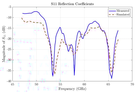
Figure 8.
Reflection coefficients, both measured and simulated, of the proposed Half-Maxwell Fish-Eye lens encased in parallel waveguides.
The antenna demonstrates excellent impedance matching to a 50 ohm system over the frequency range of 57–65 GHz, indicating a robust and efficient design. Displayed in Figure 9 are the radiation patterns of the lens antenna within the E-plane and H-plane at frequencies of 60 GHz and 63 GHz. These patterns are recorded at two distinct azimuthal angles: 0 degrees, corresponding with the lens’s primary axis, and 90 degrees, examining its orthogonal response. At 60 GHz with phi = 0 (co-polarization), as depicted in Figure 9b, the lens’s performance along its principal axis is clearly observed, showcasing its ability to maintain focus and directionality effectively. Meanwhile, at 60 GHz with phi = 90 (cross-polarization), as illustrated in Figure 9c, the radiation emissions perpendicular to the primary direction demonstrate the lens’s effectiveness in isolating the main beam from side lobes and other undesired emissions. Expanding the analysis to 63 GHz, both phi = 0 and phi = 90 are examined, as shown in Figure 9d. This comparison across different operational frequencies allows for the assessment of the stability and consistency of the lens’s performance across its operational bandwidth. It ensures that the lens meets the application-specific requirements consistently across its frequency range. The radiation patterns showcase the lens’s ability to emit radiation directionally, providing valuable insights into the antenna’s operational effectiveness and its suitability for applications necessitating precise directional control.
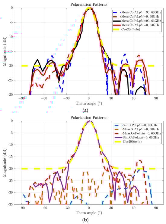
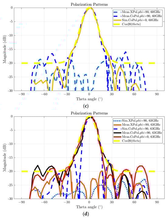
Figure 9.
The radiation patterns for the Half-Maxwell Fish-Eye (HMFE) lens, fabricated on a PCB and enclosed within parallel waveguides, are illustrated at 60 GHz and 63 GHz. (a) The radiation behavior of the lens in both the E-plane and H-plane is depicted at azimuthal angles of 0 degrees and 90 degrees. The 0-degree setting corresponds to emissions along the lens’s principal axis, offering insights into its peak directional performance. Conversely, the 90-degree setting evaluates the lens’s orthogonal emissions, crucial for assessing off-axis rejection and side-lobe levels, which are essential for applications requiring precise directional control and minimal interference. (b) Both simulated and empirical data are presented for co-polarization and cross-polarization patterns at 60 GHz when phi = 0, demonstrating primary emission characteristics and polarization purity directly forward. (c) Simulated and measured data for co-polarization and cross-polarization at 60 GHz with phi = 90 are provided, offering insights into the lens’s performance on its orthogonal plane. This assessment is vital for evaluating the lens’s ability to maintain polarization integrity and minimize cross-polarization leakage. (d) Similar datasets for 63 GHz, evaluated at both phi = 0 and phi = 90, enable an assessment across a slightly broader frequency range, indicating the stability of the lens’s performance and its operational consistency.
These comprehensive multi-angle and multi-frequency evaluations are essential for assessing the lens’s ability to maintain consistent radiation patterns and polarization integrity under diverse operational conditions, thereby confirming its reliability for advanced beamforming applications within densely populated electromagnetic environments. The detailed assessments demonstrate the antenna’s side-lobe level (SLL) in the H-plane, which remains below −10 dB at both 60 GHz and 63 GHz, ensuring minimal interference from undesired directions. Additionally, in the E-plane, the antenna exhibits cross-polarization levels greater than −19 dB at these frequencies, indicating effective polarization isolation. The radiation efficiency of the antenna, recorded as 38% at 60 GHz, is quantified by comparing the measured antenna gain with the theoretical directivity, as depicted in Figure 10. This measured efficiency reflects the performance characteristics and the inherent challenges associated with the lens design, particularly influenced by the defocused feeding mechanism utilized. Unlike traditional designs that often employ contact-based feeding strategies for lens surfaces, such as those reported for Luneburg and other lens types in Refs. [2,5,6,7], the MHFE lens antenna uses a non-contact feed, which may contribute to slightly reduced efficiency. The observed discrepancy between the actual and simulated gain could be attributed to dielectric and metal losses inherent in the substrate material, alongside potential variances introduced during the manufacturing process, affecting the overall efficacy of the antenna system.
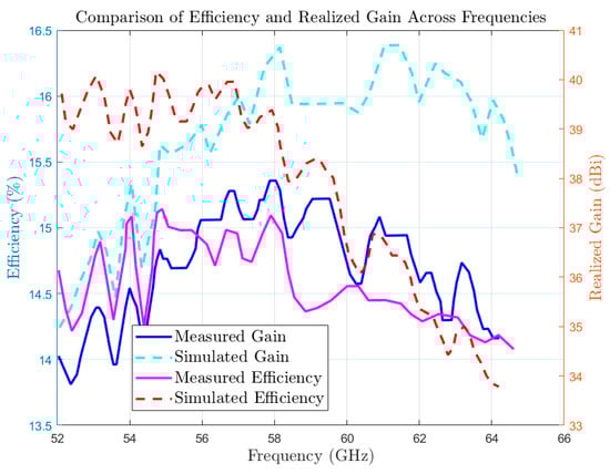
Figure 10.
Realized gain and efficiency over the operating band. This figure presents a comparison of the measured (solid lines) and simulated (dashed lines) realized gain and efficiency of the proposed Maxwell Fish-Eye lens antenna across its operational frequency range.
Figure 11 provides a detailed empirical visualization of the lens antenna’s radiation pattern, demonstrating its performance across a phi = 0 polarization state for all designated ports (from port B4 to B0). The illustration highlights how adjusting the dipole antenna position in 6 mm increments facilitates the creation of six distinct beams at the operational frequency of 60 GHz. Precise angular measurements at −37 (B4), −19 (B2), 0 (B0), +19 (B1), and +37 (B3) degrees are depicted, showcasing the antenna’s proficiency in managing radio wave emissions across a wide range of orientations. These observations are essential for understanding the antenna’s angular response and maintaining directional stability, which are critical for effective beamforming operations. The graphical representation in this figure is instrumental in assessing the antenna’s precise control and flexibility, features indispensable for applications requiring targeted and efficient radio frequency distribution.
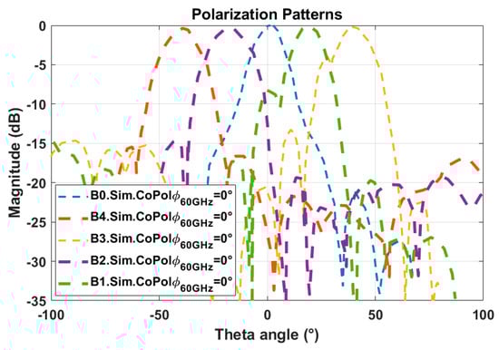
Figure 11.
Comprehensive empirical visualization of the antenna’s radiation pattern, capturing its performance in a phi = 0 polarization state across all designated ports (from port B5 to B1). It specifically showcases the impact of shifting the dipole antenna as an illuminator in 6 mm increments, resulting in the generation of six distinct beams at the operational frequency of 60 GHz. This configuration facilitates detailed measurements of directional emissions at angles of −37, −19, 0, +19, and 37 degrees, highlighting the antenna’s effectiveness in handling radio wave emissions across a diverse orientation spectrum. These measurements provide valuable insights into the antenna’s angular response and directional stability, which are essential for optimizing beamforming conditions. The graphical representation in this figure is important for evaluating the precise control and adaptability of the antenna’s emissions, which are key for applications requiring targeted and efficient radio frequency management.
The lens architecture, comprising over 400 H-shaped cells, exactly coordinates the necessary virtual permittivity, showcasing a model of engineering precision. Both simulations and experimental validations emphasize a consistent alignment between theoretical predictions and actual performance metrics. Analysis of the electric field distribution highlights that the intense radiation from the beam launcher effectively obscures the field around the wave launcher, presenting challenges in visualizing the electric field within this configuration. As incident waves traverse the lens, they transition from cylindrical waves to quasi-plane waves upon reaching the opposite boundary of the dielectric lens, yielding highly focused illumination.
Through extensive mathematical analysis and full-wave simulations, the optimal placement for the lens feed phase center, aligned with the dipole antenna, was determined to be approximately 1.8 mm from the edge of the lens. The construction of the airgap, utilizing 1 mm thick Rohacell foam [43], is highlighted as crucial for achieving the desired effective medium characteristics surrounding the Half-Maxwell Fish-Eye (HMFE) lens [5,6,7], with any deviation in thickness potentially impacting the lens’s intended performance significantly.
Figure 12 encapsulates the comprehensive eight-step process for the design and optimization of the HMFE lens, mapping out the journey from conceptualization to final construction. It delineates each critical development phase, covering design simulations, material selections, refinement of refractive index profiles, integration of the antenna, and analytical assessment of the prototype to ensure peak performance and meticulous precision in the completed lens.

Figure 12.
The eight-step process for designing and optimizing the HMFE Lens. Each step represents a critical phase in the development, from the initial concept, design simulations, and material selection to the refinement of refractive index profiles, antenna integration, and final prototype analysis, ensuring optimal performance and precision in the lens’s final construction.
6. Comparative Analysis and Design Evolution
Historically, the design of GRIN lens antennas [2], specifically those utilizing Maxwell Fish-Eye lenses [4,5,46,47,48,49,50,51], focused on traditional dielectric materials, which presented substantial challenges in design and analysis due to their inherent limitations and inefficiencies [2]. However, the evolution of manufacturing technologies such as 3D printing [2,8], which leverages porosity techniques [2,3,6] and material reduction strategies [2], alongside innovations in printed circuit board (PCB) metamaterial cells [4,5,7], has revitalized interest in these structures due to their cost-effectiveness and practical implementation potential [4,5,7].
Despite these advancements [2], both mentioned implementation approaches come with their own set of technical and design limitations [4,5,7]. This presents a significant research opportunity to focus on GRIN structures [2,9,33,34], particularly through the application of metasurface cells [4,5,7,33,34]. These cells align incident waves parallel to the cell structure [4,5,7], differentiating from prior work where perpendicular incident waves were typically used for focusing, which are reported in [32,33,34,35]. Our study is among the few to explore the application of parallel incident waves with meta-cells at millimeter-wave frequencies [4]. These types of cells are notably sensitive and have narrowband characteristics, which is why we employ a sandwiched parallel quasi-TEM implementation for their realization.
At the heart of the antenna’s design is the HMFE lens, renowned for its precise focusing capabilities of electromagnetic waves [2,3]. Integrating a dipole antenna within a parallel-plate waveguide to illuminate this lens underscores a sophisticated design strategy aimed at maximizing directional emission [4,5]. Selecting 60 GHz is strategic, situating the antenna within the millimeter-wave (mmWave) spectrum [46]. This choice is advantageous for IoT applications [45], offering a high data transmission rate and reduced device interference in the operating area. The employment of metasurface technology enables the precise manipulation of wavefronts, which is vital in densely populated IoT settings [46]. This technology enhances the lens’s ability to direct wavefronts accurately to desired focal points, thereby boosting signal strength and quality. In scenarios like smart cities, industrial environments, or smart agricultural farms [46], maintaining robust and reliable connections among numerous devices is essential.
In the mentioned scenarios, the antenna’s ability to dynamically guide beams can significantly reduce energy consumption and enhance network efficiency by targeting specific areas or devices when needed. By managing beam direction and strength effectively [46,47,48,49,50,51], the antenna supports a higher number of simultaneous connections without compromising network performance. Additionally, the precise control over electromagnetic waves minimizes loss and interference, challenges that are prevalent in urban and industrial IoT deployments [46].
The MHMF lens antenna’s directivity marks a substantial advance in IoT communications technology. Its innovative design not only addresses but also effectively resolves several critical challenges within densely interconnected environments, such as signal degradation, interference, and network congestion. Consequently, this antenna not only improves the performance and connectivity of IoT networks but also broadens the scope for future IoT applications requiring dependable and efficient communication across diverse and challenging settings. As this technology evolves, it is poised to play a pivotal role in advancing smart platform infrastructures and industrial IoT solutions, establishing it as a significant innovation in the field of advanced antenna systems.
Comparison
The assessment of Maxwell Fish-Eye lens antenna designs centers on critical electrical performance metrics such as realized gain, typical bandwidth, and the incorporation of multibeam capabilities or specialized feed networks. These elements are crucial for their effectiveness at millimeter-wave frequencies. To date, our investigations have not uncovered any documented implementations of printed Half-Maxwell Fish-Eye (HMFE) lenses operating at 60 GHz as described here. The prevailing studies in this area, noted in references [46,47,48,49,50,51], primarily discuss dielectric-based implementation approaches [2]. Comparatively, the antenna designs that most closely match the performance characteristics of our high-gain lens antenna are array antennas. Nonetheless, a notable benefit of our lens antenna design, as highlighted in references [34,35,36,37,38,39,40], is its capacity to address and overcome several significant challenges commonly associated with array antennas, as compared in Table 1.

Table 1.
Evaluating the proposed HMFE lens against other antenna arrays in millimeter-wave frequency bands and a single X-band lens.
Specifically, lens antennas avoid the necessity for extensive, expensive millimeter-wave substrates and intricate [34], costly manufacturing processes. Moreover, they eliminate the need for complex feed network designs [34,35,36,37,38,39,40], which simplifies the overall antenna implementation and significantly reduces associated costs. This simplification not only streamlines the development process but also enhances the economic viability of deploying advanced lens antennas in millimeter-wave applications.
The bowtie arrays [34,36] and Vivaldi arrays [35,37,38,39,40] exemplify a combination of high directional gains and noteworthy bandwidths. For example, a 1 × 8 bowtie array at 62 GHz delivers a 20.0 dBi gain with a 16.3% bandwidth, utilizing an SIW feeding network that improves power distribution and integration, alongside beamforming capabilities enabled by a beamforming feed network. Similarly, Vivaldi arrays [35], particularly those with SIW feed networks, present a well-rounded performance, with gains up to 15.9 dBi and bandwidths extending to 14.7%. The necessity for a feed network suggests a possible rise in design complexity but also indicates their suitability for high-performance applications. Notably, radiation efficiency is reported exclusively in [34] as 82% at a single frequency, so this study does not employ efficiency as a comparative metric.
Regarding lens-based mechanisms [6,7], these antenna designs represent a significant shift from traditional array configurations. The Dielectric Sphere Fish antenna [6] achieves the highest gain among the studies referenced in Table 1, notably 21 dBi at 82 GHz, despite its relatively limited bandwidth of 6.37%, due to its operational high frequency. In contrast, the Maxwell Fish-Eye lens [5,7] displays an encouraging balance between gain and bandwidth, reaching a 15 dBi gain and a 16.95% bandwidth at 62 GHz. This underscores its capability for wideband applications and the potential for multibeam operations by incorporating different beam sources or moving source mechanisms.
The analysis of these antenna designs reveals crucial trade-offs among gain, bandwidth, and the challenges linked to feed networks and multibeam capabilities. The selection between array and lens-based designs is largely determined by the specific requirements of the application, such as the need for directional communication, bandwidth requirements, and system integration complexities. Array antennas [34,35,36,37,38,39,40] are noted for their versatility and the ability for beam steering and shaping, which are essential in dynamic communication settings. Their performance is significantly boosted by SIW feed networks or microstrips, which optimize power distribution and integration.
Lens-based antennas, including our design and those referenced in [5,6,7], offer unique benefits in precisely focusing and directing electromagnetic waves. Their performance in the mmWave domain, particularly in terms of bandwidth and dynamic beam steering (as demonstrated by the inclusion of moving sources), positions them as strong candidates for mobile and stationary communication systems, as well as IoT applications requiring high efficiency and adaptability.
In conclusion, although pursuing higher gains in the mmWave spectrum with array structures introduces complexity and the potential for loss, investing in the design of reliable structures can yield significant benefits in terms of bandwidth, efficiency, gain, and directivity.
7. Internet-of-Things Detailed Scenario: Smart Agriculture System Using Directive MHMF Lens Antenna
The deployment of the directive Metasurface Half-Maxwell Fish-Eye (MHMF) lens antenna within a smart agriculture IoT system illustrates the revolutionary impact of cutting-edge antenna technology on farming practices. This advanced system is particularly effective in extensive agricultural fields and incorporates a comprehensive suite of sensors, including soil moisture sensors, temperature gauges, nutrient-level detectors, and crop health monitors. These sensors can be integrated into a variety of farm equipment, such as harvesters, laser weed control devices, or tractors, making the MHMF antenna a crucial component for data collection. The flexibility of the system’s configuration allows for customization to meet specific agricultural requirements or budget constraints, offering the possibility to expand data collection capabilities by adding more machines and sensors.
Operating at 60 GHz, the MHMF antenna minimizes interference from the typical rural wireless frequencies that are occupied by other devices, which generally operate at lower frequencies. This selection of a higher frequency facilitates larger bandwidths, thus enabling greater data throughput essential for the rapid transmission of complex sensor data and the receipt of detailed control commands. Moreover, the system features dynamic beam steering, which permits the lens antenna to alter the direction and focus of each beam in real time. This capability can be adjusted according to operational demands, directional needs, and sensor locations, thereby optimizing signal strength and minimizing interference. This dynamic adaptability ensures that the system maintains high performance and reliability, crucial for the precise and efficient operation of modern smart farming technologies.
In this extensive setup, the directive MHMF lens antenna is crucial, positioned strategically either at a central point, which can be a movable machine such as a tractor and robotic devices, or across multiple high points on the farm to ensure comprehensive coverage, as shown in Figure 13. This strategic placement significantly enhances the system’s capacity to monitor and manage agricultural operations effectively. Mounted on either robotic or humanoid-driven machinery equipped with ancillary devices for tasks such as watering, fertilizing, or weed control, the antenna enables real-time monitoring and precise intervention capabilities. It is configured for multibeam output, which allows it to sustain communication links with various devices simultaneously, efficiently covering different areas of the farm, as shown in Figure 13 and Figure 14. As depicted in Figure 14, tractors are equipped with various units specifically designed for data gathering and operational feedback. This illustration emphasizes the role of these tractors as dynamic mobile data collection platforms which are fully integrated into the farm’s extensive data acquisition and management system, maintaining constant communication links with sensors. Reflecting the scenario presented in Figure 13, among the essential sensors utilized in this IoT network are the soil moisture sensors, which are crucial in both simple and complex IoT setups. Strategically positioned at various depths across the farm, highlighted with white nodes, these sensors diligently monitor moisture levels to effectively manage irrigation systems. This is particularly vital for optimizing water usage and enhancing the growth of high-value crops such as lavender and asparagus.
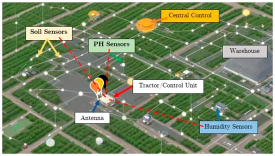
Figure 13.
This figure depicts the directive MHMF lens antenna positioned centrally and strategically distributed throughout the farm to ensure comprehensive coverage. This setup facilitates dynamic beam steering, allowing multiple beams to be adjusted in real time based on sensor feedback and operational requirements. These real-time adjustments are essential for optimizing signal strength, minimizing interference, and enhancing the accuracy and efficiency of data transmission. The white node links represent either wired or wireless connections, connecting specific sensors to a central control unit, which acts as the decision-making hub. The data collected by tractors equipped with various antennas are transmitted back to this central unit, enabling timely and informed responses to field conditions [52].
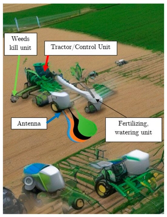
Figure 14.
This figure depicts tractors equipped with various units designed to collect data and provide operational feedback [52].
Expanding on the scenario presented in Figure 13, temperature and humidity sensors are strategically placed across the farm to monitor micro-climatic conditions impacting crop growth. These sensors can also be mounted on machinery for site-specific data collection. pH sensors, indicated by white squares, are directly embedded in the soil to provide precise real-time monitoring. As machinery traverses the farm, it collects pH data and adjusts soil treatments promptly by applying necessary chemicals to modify soil acidity. This process is crucial for maintaining optimal soil conditions and enhancing nutrient uptake. Furthermore, nutrient sensors are utilized to monitor key elements such as nitrogen, phosphorus, calcium, and potassium levels in the soil, offering essential data for precise fertilization strategies. Additionally, crop health sensors, equipped with cameras or spectral sensors, assess plant health and detect diseases or deficiencies, enabling targeted actions like accurate pesticide application or focused nutrient supplementation. These sensors can be strategically distributed across different areas of the farm, as highlighted by the white nodes in Figure 13.
All of these sensors are equipped with wireless capabilities, utilizing low-energy technologies such as LoRaWAN or Zigbee to enable efficient communication with the central unit or the MHMF antenna mounted on tractors or robotic machines, as illustrated in Figure 14. To guarantee continuous operation with minimal maintenance, these sensors are typically either solar-powered or equipped with long-lasting batteries, enhancing the sustainability and reliability of the system. This robust integration of advanced sensors and communication technologies significantly elevates agricultural productivity and sustainability, illustrating the vast potential of modern farming operations powered by sophisticated IoT solutions.
Complementing the comprehensive sensor integration, drones and automated vehicles constitute another vital component of this smart agriculture IoT system. Utilizing low-speed drones, copter drones, or a combination of these drones with robotic tractors enables aerial imaging and detailed data collection, which are invaluable for efficiently monitoring expansive areas. Automated ground vehicles are deployed for specific field tasks such as seeding, weed control, pesticide spraying, and harvesting, each optimized according to real-time data received from the system.
These vehicles and drones are equipped with embedded communication modules that seamlessly interact with the MHMF antenna or control unit, allowing for real-time control, operational adjustments, and efficient data transfer. This ensures that all autonomous activities are coordinated and managed centrally. For example, automated irrigation systems in this setup include controllable valves, pumps, and sprinklers directly linked to soil moisture sensors. These systems adjust water distribution based on real-time moisture data, markedly optimizing water use and reducing wastage.
The backbone of this smart agriculture system is a robust data management and analytics platform that processes large volumes of data generated by the various sensors and devices. Running on advanced analytics software, either hosted on cloud platforms or local servers, this platform is designed to handle the data demands of very large farms. This system’s analytics capabilities provide actionable insights, forecast trends, and issue alerts or adjustments directly to the connected devices, ensuring that all farm operations are data-driven and responsive to changing conditions. The communication network, centered around the MHMF antenna, is primarily wireless, leveraging IoT-friendly protocols that support low-power operations. This setup might require the addition of repeaters or secondary antennas, especially in extensive or complex terrains, to ensure uninterrupted coverage across the entire farm. However, our analysis indicates that dedicating specific frequencies for sensors, which then gather data via the lens antenna and transmit it to the central control unit—highlighted in yellow in Figure 13—results in low interference and a more reliable performance. Therefore, in terms of scaling, adjustments are only needed in the communication links to accommodate different farm sizes.
The user interface (UI) of this system, accessible via a web portal or mobile app, allows farmers to easily access real-time data, receive notifications, and manually adjust system parameters as needed. The UI includes features such as real-time monitoring dashboards, historical data analysis, and automated reporting tools, which provide a comprehensive overview of farm operations and facilitate informed decision-making.
In conclusion, this smart agriculture system offers significant advantages over conventional farming methods by reducing resource wastage and enhancing crop yields through optimized growing conditions. Such improvements not only lower operational costs but also contribute to increased profitability. Furthermore, by optimizing resource application and minimizing waste, the system upholds sustainable farming practices, addressing global environmental concerns. The scalability of the system’s design allows for the integration of additional sensors and equipment without extensive changes, simply by adjusting the antenna’s beamforming capabilities to extend coverage as needed. By leveraging the directive MHMF lens antenna, this advanced technology setup exemplifies how innovative solutions can transform traditional farming into a more efficient, profitable, and sustainable operation, demonstrating the profound potential of integrating cutting-edge antenna technology into agricultural practices.
8. Conclusions
In conclusion, this study not only presents a significant advancement in antenna technology with the development of the directive Metasurface Half-Maxwell Fish-Eye (MHMF) lens antenna but also highlights its revolutionary impact on IoT networks and specifically on smart agriculture systems. Operating at the critical frequency of 60 GHz, this antenna system, designed with a dipole antenna integrated into a parallel-plate waveguide, effectively illuminates an HMFE lens to achieve the high gain essential for robust IoT operations. The incorporation of metasurface structures to create a gradient refractive index on the lens surface, alongside meticulous design and optimization of the antenna’s unit cells, underscores a pioneering approach to enhancing IoT connectivity and network capabilities. The antenna’s operational efficacy, confirmed through extensive numerical simulations and further validated by the construction and testing of a functional prototype, aligns closely with the anticipated high-gain performance. This validation not only verifies the antenna’s role as an indispensable component of IoT infrastructure but also exemplifies the seamless integration of metasurface technology and sophisticated design methodologies in the development of efficient, high-performance antenna systems.
Furthermore, the adaptability of gradient refractive index materials in crafting state-of-the-art microwave lens technologies is demonstrated, showing that precise manipulation of electromagnetic wave propagation can profoundly influence the development of innovative devices like the directive MHMF lens antenna. This study leverages novel design concepts to create adaptable, high-gain antenna solutions, marking a significant achievement in the quest for improved connectivity and performance in IoT systems.
Specifically, in the field of smart agriculture, the directive MHMF lens antenna enhances agricultural productivity and sustainability by enabling real-time monitoring and precise management of farming operations. Its strategic placement on farm machinery or at high points on the farm ensures comprehensive coverage and dynamic beam steering, adapting to operational demands and sensor locations to optimize signal strength and minimize interference. This advanced technology setup transforms traditional farming into a more efficient, profitable, and sustainable operation, showcasing the profound potential of integrating cutting-edge antenna technology into agricultural practices. The scalability of the system’s design allows for the integration of additional sensors and equipment without extensive changes, simply by adjusting the antenna’s beamforming capabilities to extend coverage as needed.
Author Contributions
Conceptualization, J.P. and T.A.D.; methodology, J.P.; software, J.P.; validation, J.P., T.A.D. and B.S.V.; investigation, J.P.; resources, J.P.; data curation, J.P.; writing—original draft preparation, J.P. and B.S.V.; writing—review and editing, J.P. and B.S.V.; visualization, J.P. and B.S.V.; supervision, T.A.D.; project administration, J.P. and T.A.D.; funding acquisition, T.A.D. All authors have read and agreed to the published version of the manuscript.
Funding
This research received no external funding.
Data Availability Statement
The data are contained within the article.
Acknowledgments
The authors extend their sincere gratitude to https://www.presentationgo.com/ (accessed on 1 March 2024) for their generous provision of a block diagram template at no charge, which was instrumental in facilitating our academic research. This document represents the culmination of comprehensive doctoral research undertaken with the support of a full scholarship from INRS-EMT. For those seeking further details on this field of research, Ref. [10] provides an in-depth discussion in Chapter 4 (pages 78–92). We are deeply thankful to INRS for providing the academic environment and support that enabled us to conduct this significant research project. Our heartfelt appreciation also goes to Rohacell USA for supplying various foam thicknesses that were critical for our project, meeting our academic needs from 2014 to 2018. Additionally, we are grateful to https://deepai.org/ (accessed on 1 March 2024) for supplying the templates for Figure 11 and Figure 12. These templates allowed us to add specific details and effectively illustrate the application scenario for a smart agriculture IoT system.
Conflicts of Interest
The authors declare no conflicts of interest.
References
- Schurig, D.; Mock, J.J.; Justice, B.J.; Cummer, S.A.; Pendry, J.B.; Starr, A.F.; Smith, D.R. Metamaterial electromagnetic cloak at microwave frequencies. Science 2006, 314, 977–980. [Google Scholar] [CrossRef] [PubMed]
- Pourahmadazar, J. New Millimetric Lens Antennas Using Periodic Porous Plastic Structures. Ph.D. Thesis, Université du Québec, Institut National de la Recherche Scientifique, Montreal, QC, Canada, 2018. (In English). [Google Scholar]
- Pourahmadazar, J.; Denidni, T.A. Towards Millimeter-wavelength: Transmission-Mode Fresnel-Zone Plate Lens Antennas using Plastic Material Porosity Control in Homogeneous Medium. Sci. Rep. 2018, 8, 5300. [Google Scholar] [CrossRef] [PubMed]
- Dhouibi, A.; Burokur, S.N.; de Lustrac, A.; Priou, A. Low-Profile Substrate-Integrated Lens Antenna Using Metamaterials. IEEE Antennas Wirel. Propag. Lett. 2013, 12, 43–46. [Google Scholar] [CrossRef]
- Dhouibi, A.; Burokur, S.N.; de Lustrac, A.; Priou, A. Broadband metamaterial-based half Maxwell fish-eye lens antenna. In Proceedings of the 2013 IEEE Antennas and Propagation Society International Symposium (APSURSI), Orlando, FL, USA, 7–13 July 2013; pp. 1294–1295. [Google Scholar] [CrossRef]
- Fuchs, B.; Lafond, O.; Rondineau, S.; Himdi, M.; Le Coq, L. Design and characterisation of half Maxwell Fish Eye lens antenna in 76–81 Ghz band. Electron. Lett. 2006, 42, 261–263. [Google Scholar] [CrossRef]
- Dhouibi, A.; Burokur, S.N.; de Lustrac, A.; Priou, A. Metamaterial-based half Maxwell fish-eye lens for broadband directive emissions. Appl. Phys. Lett. 2013, 102, 024102. [Google Scholar] [CrossRef]
- Pourahmadazar, J.; Sahebghalam, S.; Aghdam, S.A.; Nouri, M. A Millimeter-Wave Fresnel Zone Plate Lens Design Using Perforated 3D Printing Material. In Proceedings of the 2018 IEEE MTT-S International Microwave Workshop Series on Advanced Materials and Processes for RF and THz Applications (IMWS-AMP), Ann Arbor, MI, USA, 16–18 July 2018; pp. 1–3. [Google Scholar] [CrossRef]
- Ding, T.; Yi, J.; Li, H.; Zhang, H.; Burokur, S.N. 3D field-shaping lens using all-dielectric gradient refractive index materials. Sci. Rep. 2017, 7, 782. [Google Scholar] [CrossRef]
- Andrews, J.G.; Buzzi, S.; Choi, W.; Hanly, S.V.; Lozano, A.; Soong, A.C.; Zhang, J.C. What Will 5G Be? IEEE J. Sel. Areas Commun. 2014, 32, 1065–1082. [Google Scholar] [CrossRef]
- Li, Y.; Ge, L.; Chen, M.; Zhang, Z.; Li, Z.; Wang, J. Multibeam 3-D-Printed Luneburg Lens Fed by Magnetoelectric Dipole Antennas for Millimeter-Wave MIMO Applications. IEEE Trans. Antennas Propag. 2019, 67, 2923–2933. [Google Scholar] [CrossRef]
- Thornton, J. Lens antenna for multi-satellite and multi-frequency band communications on trains. IET Conf. Proc. 2007, 95–103. [Google Scholar] [CrossRef]
- Diallo, C.D.; Girard, E.; Legay, H.; Sauleau, R. All-metal Ku-band Luneburg lens antenna based on variable parallel plate spacing Fakir bed of nails. In Proceedings of the 2017 11th European Conference on Antennas and Propagation (EUCAP), Paris, France, 19–24 March 2017; pp. 1401–1404. [Google Scholar] [CrossRef]
- Hay, S.G.; Archer, J.W.; Timms, G.P.; Smith, S.L. A beam-scanning dual-polarized fan-beam antenna suitable for Millimeter wavelengths. IEEE Trans. Antennas Propag. 2005, 53, 2516–2524. [Google Scholar] [CrossRef]
- Park, Y.-J.; Wiesbeck, W. Offset cylindrical reflector antenna fed by a parallel-plate Luneburg lens for automotive radar applications in millimeter-wave. IEEE Trans. Antennas Propag. 2003, 51, 2481–2483. [Google Scholar] [CrossRef]
- Demmerle, F.; Kern, S.; Wiesbeck, W. A bi-conical multibeam antenna for space division multiple access. IEEE Trans. Antennas Propag. 1997, 2, 1082–1085. [Google Scholar] [CrossRef]
- Lee, J.J. Lens Antennas. In Antenna Handbook; Lo, Y.T., Lee, S.W., Eds.; Springer: Boston, MA, USA, 1988. [Google Scholar] [CrossRef]
- Peeler, G.; Archer, D. A two-dimensional microwave luneberg lens. Trans. IRE Prof. Group Antennas Propag. 1953, 1, 12–23. [Google Scholar] [CrossRef]
- Rondineau, S.; Himdi, M.; Sorieux, J. A sliced spherical Luneburg lens. IEEE Antennas Wirel. Propag. Lett. 2003, 2, 163–166. [Google Scholar] [CrossRef]
- Sato, K.; Ujiie, H. A plate Luneberg lens with the permittivity distribution controlled by hole density. Electron. Comm. Jpn. Pt. I 2002, 85, 1–12. [Google Scholar] [CrossRef]
- Xin, H.; Liang, M. 3-D-Printed Microwave and THz Devices Using Polymer Jetting Techniques. Proc. IEEE 2017, 105, 737–755. [Google Scholar] [CrossRef]
- Liang, M.; Yu, X.; Sabory-García, R.; Ng, W.-R.; Gehm, M.E.; Xin, H. Direction of arrival estimation using Luneburg lens. In Proceedings of the 2012 IEEE/MTT-S International Microwave Symposium Digest, Montreal, QC, Canada, 17–22 June 2012; pp. 1–3. [Google Scholar] [CrossRef]
- Dhouibi, A.; Burokur, S.N.; de Lustrac, A.; Priou, A. Compact Metamaterial-Based Substrate-Integrated Luneburg Lens Antenna. IEEE Antennas Wirel. Propag. Lett. 2012, 11, 1504–1507. [Google Scholar] [CrossRef]
- Liang, M.; Ng, W.-R.; Chang, K.; Gbele, K.; Gehm, M.E.; Xin, H. A 3-D Luneburg Lens Antenna Fabricated by Polymer Jetting Rapid Prototyping. IEEE Trans. Antennas Propag. 2014, 62, 1799–1807. [Google Scholar] [CrossRef]
- Gbele, K.; Liang, M.; Ng, W.-R.; Gehm, M.E.; Xin, H. Millimeter wave luneburg lens antenna fabricated by polymer jetting rapid prototyping. In Proceedings of the 2014 39th International Conference on Infrared, Millimeter, and Terahertz Waves (IRMMW-THz), Tucson, AZ, USA,, 14–19 September 2014; p. 1. [Google Scholar] [CrossRef]
- Liang, M.; Xin, H. Design of additive manufactured Luneburg Lens working at W-band. In Proceedings of the 2015 USNC-URSI Radio Science Meeting (Joint with AP-S Symposium), Vancouver, BC, Canada, 19–25 July 2015; p. 354. [Google Scholar] [CrossRef]
- Petosa, A.; Gagnon, N.; Ittipiboon, A. Effects of Fresnel lens thickness on aperture efficiency. In Proceedings of the 2004 10th International Symposium on Antenna Technology and Applied Electromagnetics and URSI Conference, Ottawa, ON, Canada, 20–23 July 2004; pp. 1–4. [Google Scholar] [CrossRef]
- Pfeiffer, C.; Grbic, A.; Printed, A. Broadband Luneburg Lens Antenna. IEEE Trans. Antennas Propag. 2010, 58, 3055–3059. [Google Scholar] [CrossRef]
- Zhang, S.; Arya, R.K.; Pandey, S.; Vardaxoglou, Y.; Whittow, W.; Mittra, R. 3D-printed planar graded index lenses. IET Microw. Antennas Propag. 2016, 10, 1411–1419. [Google Scholar] [CrossRef]
- Liang, M.; Xin, H. Three-Dimensionally Printed/Additive Manufactured Antennas. In Handbook of Antenna Technologies; Chen, Z., Ed.; Springer: Singapore, 2015. [Google Scholar] [CrossRef]
- Cheng, D. Modified luneburg lens for defocused source. IRE Trans. Antennas Propag. 1960, 8, 110–111. [Google Scholar] [CrossRef]
- Dadgarpour, A.; Zarghooni, B.; Virdee, B.S.; Denidni, T.A. Beam tilting antenna using integrated metamaterial loading. IEEE Trans. Antennas Propag. 2014, 62, 2874–2879. [Google Scholar] [CrossRef]
- Dadgarpour, A.; Zarghooni, B.; Virdee, B.S.; Denidni, T.A. Beam deflection using gradient refractive-index media for 60-GHz end-fire antenna. IEEE Trans. Antennas Propag. 2015, 63, 3768–3774. [Google Scholar] [CrossRef]
- Dadgarpour, A.; Antoniades, M.A.; Sebak, A.; Kishk, A.A.; Sorkherizi, M.S.; Denidni, T.A. High-Gain 60 GHz Linear Antenna Array Loaded With Electric and Magnetic Metamaterial Resonators. IEEE Trans. Antennas Propag. 2020, 68, 3673–3684. [Google Scholar] [CrossRef]
- Liu, P.; Zhu, X.; Jiang, Z.H.; Zhang, Y.; Tang, H.; Hong, W. A compact single-layer q-band tapered slot antenna array with phaseshifting inductive windows for endfire patterns. IEEE Trans. Antennas Propag. 2019, 67, 169–178. [Google Scholar] [CrossRef]
- Park, S.-J.; Shin, D.-H.; Park, S.-O. Low Side-Lobe Substrate-Integrated-Waveguide Antenna Array Using Broadband Unequal Feeding Network for Millimeter-Wave Handset Device. IEEE Trans. Antennas Propag. 2016, 64, 923–932. [Google Scholar] [CrossRef]
- Zhu, S.; Liu, H.; Wen, P. A new method for achieving miniaturization and gain enhancement of Vivaldi antenna array based on anisotropic metasurface. IEEE Trans. Antennas Propag. 2019, 67, 1952–1956. [Google Scholar] [CrossRef]
- Liu, P.; Zhu, X.; Wang, X.; Tian, L. A SIW-based Vivaldi array antenna for 5G wireless communication systems. In Proceedings of the IEEE International Symposium on Antennas and Propagation USNC/URSI National Radio Science Meeting, San Diego, CA, USA, 9–14 July 2017; pp. 529–530. [Google Scholar] [CrossRef]
- Li, A.; Luk, K.-M.; Li, Y. A dual linearly polarized end-fire antenna array for the 5G applications. IEEE Access 2018, 6, 78276–78285. [Google Scholar] [CrossRef]
- Sun, M.; Chen, Z.N.; Qing, X. Gain enhancement of 60-GHz antipodal tapered slot antenna using zero-index metamaterial. IEEE Trans. Antennas Propag. 2013, 61, 1741–1746. [Google Scholar] [CrossRef]
- Ansys HFSS Software. Available online: https://www.ansys.com/ (accessed on 1 March 2024).
- Roger, R.T. Duroid 5880, 5870laminates, USA, 2018. Available online: https://www.rogerscorp.com/advanced-electronics-solutions/rt-duroid-laminates/rt-duroid-5880-laminates (accessed on 1 March 2024).
- High-performane Foam Cores for Sandwich Structures Rohacell. Available online: https://composites.evonik.com/en/products-services/foams/rohacell (accessed on 1 March 2024).
- MATLAB for Artificial Intelligence. Available online: https://www.mathworks.com/ (accessed on 1 March 2024).
- Southwest Microwave. Available online: https://southwestmicrowave.com/ (accessed on 1 March 2024).
- Cai, Z.; Zhou, Y.; Qi, Y.; Zhuang, W.; Deng, L. A Millimeter Wave Dual-Lens Antenna for IoT-Based Smart Parking Radar System. IEEE Int. Things J. 2021, 8, 418–427. [Google Scholar] [CrossRef]
- Yang, X.; Ji, Y.; Hu, J.; Ge, L.; Li, Y.; Luk, K.M. Wideband Quasi-Spherical Lens Antenna Module with 2-D Switched Beams for 5G Millimeter-Wave IoT Applications. IEEE Int. Things J. 2024, 11, 1217–1227. [Google Scholar] [CrossRef]
- Pourahmadazar, J.; Virdee, B.S.; Denidni, T.A. Advancing into Millimeter Wavelengths for IoT: Multibeam Modified Planar Luneburg Lens Antenna with Porous Plastic Material. Electronics 2024, 13, 1605. [Google Scholar] [CrossRef]
- Fuchs, B.; Lafond, O.; Rondineau, S.; Himdi, M. Design and characterization of half Maxwell fish-eye lens antennas in millimeter waves. IEEE Trans. Microw. Theory Tech. 2006, 54, 2292–2300. [Google Scholar] [CrossRef]
- Huang, M.; Yang, S.; Gao, F.; Quarfoth, R.; Sievenpiper, D. A 2-D Multibeam Half Maxwell Fish-Eye Lens Antenna Using High Impedance Surfaces. IEEE Antennas Wirel. Propag. Lett. 2014, 13, 365–368. [Google Scholar] [CrossRef]
- Fuchs, B.; Lafond, O.; Palud, S.; Le Coq, L.; Himdi, M.; Buck, M.C.; Rondineau, S. Comparative Design and Analysis of Luneburg and Half Maxwell Fish-Eye Lens Antennas. IEEE Trans. Antennas Propag. 2008, 56, 3058–3062. [Google Scholar] [CrossRef]
- DeepAI. Available online: https://deepai.org/ (accessed on 1 March 2024).
Disclaimer/Publisher’s Note: The statements, opinions and data contained in all publications are solely those of the individual author(s) and contributor(s) and not of MDPI and/or the editor(s). MDPI and/or the editor(s) disclaim responsibility for any injury to people or property resulting from any ideas, methods, instructions or products referred to in the content. |
© 2024 by the authors. Licensee MDPI, Basel, Switzerland. This article is an open access article distributed under the terms and conditions of the Creative Commons Attribution (CC BY) license (https://creativecommons.org/licenses/by/4.0/).