Communication

Experimental Study of Magnetron’s Power-Pulled Characteristic to Realize a Quasi-Dual-Frequency Microwave Output

1
School of Electronics and Information Engineering, Sichuan University, Chengdu 610064, China
2
Yibin Industrial Technology Research Institute of Sichuan University, Yibin 644000, China
*
Author to whom correspondence should be addressed.
Electronics 2024, 13(7), 1323; https://doi.org/10.3390/electronics13071323
Submission received: 25 February 2024 / Revised: 25 March 2024 / Accepted: 28 March 2024 / Published: 1 April 2024

Abstract

:
This article presents experimental evidence demonstrating the feasibility of implementing a quasi-dual-frequency microwave signal generator using a 1 kW commercial magnetron. The injection-pulled magnetron may generate quasi-dual-frequency output with nearly identical amplitudes by injecting signal at specific powers and frequencies out of the Adler locking band. This generator offers the advantage of developing a large-power and tunable quasi-dual-frequency signal at low cost and with simple implementation. In the present study, a tunable quasi-dual-frequency signal with a frequency interval ranging from 0.48 MHz to 13.74 MHz is generated experimentally. Furthermore, the effects of anode voltage ripples on the dual-frequency outputs are experimentally investigated. An empirical relationship between the frequency interval and injection ratio is obtained and presented. In addition, neither the output power nor the efficiency of the magnetron in the dual-frequency mode decreases. This research is promising for improving microwave heating uniformity in large-scale industrial applications.

1. Introduction

Microwave heating has become increasingly popular in food processing, plastic manufacturing, and other forms of industrial production due to its advantages related to time and energy efficiency [1,2,3]. The most widely used microwave heating devices are single-frequency microwave generators. However, realizing uniformity in microwave heating is challenging [4,5].
Recently, multi-frequency heating has attracted significant attention due to its ability to improve the uniformity of microwave heating [6,7,8]. Current research on multi-frequency heating is dominated by experimental studies that combine several solid-state sources at different operating frequencies [9,10]. However, the increasing cost and relatively low efficiency of this method limit its large-scale industrial application.
Magnetrons, given their low price point, high efficiency, and high output power, are promising candidates for large-scale microwave heating [11,12,13]. Their spectral characteristics may be improved by injection-locking techniques [14,15,16]. Chen et al. proposed a method to control the anode voltage ripple of an injection-locked magnetron using an adjustable capacitor module. They demonstrated that the spectrum of the magnetron output changed under various voltage ripples [17]. Ha et al. experimentally explored the effects of three switching-mode power supplies with different voltage ripples on the magnetron outputs. Using power supplies with various voltage ripples resulted in significant differences in the magnetron outputs [18].
The technology of multi-frequency heating using magnetrons has also been investigated in recent years. Yang et al. proposed that frequency-scanning heating schematics at frequencies shifting between 2.43 and 2.45 GHz can significantly improve microwave heating uniformity [19]. Du et al. demonstrated that multi-frequency magnetrons can efficiently improve heating uniformity. A frequency interval between 3.6 and 10 MHz efficiently improved heating uniformity and performance in their study [20]. However, high system costs and design complexity are still barriers to large-scale industrial application. This paper proposes a simple, cost-effective method to generate tunable quasi-dual-frequency microwaves using a single commercial magnetron. This approach may enhance the performance of microwave heating.
In this paper, an injected-pulled magnetron is utilized to generate a quasi-dual-frequency microwave output with adjustable frequency intervals. The tuning of the dual-frequency microwave output’s characteristics is achieved by modifying the power and frequency of the injected reference signal. Two sets of comparison experiments are also conducted using different anode voltage ripples to investigate the effect of voltage ripples on the resulting dual-frequency output. As the injection power increases from 32 to 47 dBm, the dual-frequency interval of the quasi-dual-frequency output can be tuned within the range of 0.48 to 13.74 MHz. Additionally, the output power of the quasi-dual-frequency magnetron does not decrease. This study is of significant importance in enhancing heating uniformity in microwave heating.

2. Theoretical and Numerical Analysis

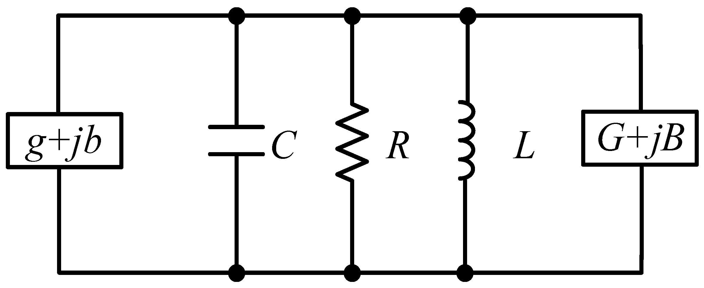
2.1. Injection Locking of a Magnetron

As a large-power oscillator, a magnetron usually oscillates near its resonant angular frequency. According to Slater’s research, a magnetron operating in a single mode can be equivalent to a parallel resonant resistor-inductor-capacitor (RLC) circuit [21,22,23].
As shown in Figure 1, R is the equivalent resistance, L is the equivalent inductance, and C is the equivalent capacitance. g + jb is regarded as the equivalent magnetron admittance, and G + jB is the equivalent load admittance. The circuit equation of the magnetron at the free-running state is therefore obtained as:
g + j b C ω 0 = j ω ω 0 ω 0 ω + 1 Q 0 + G + j B Q e x t
where ω is the magnetron’s output frequency, ω0 is the angular frequency of the resonant cavity, and Q0 and Qext are the intrinsic quality factor and external quality factor, respectively, of the resonant circuit.
When a low-power reference signal at a frequency around ω0 is injected, the injected signal can be equivalent to the parallel load of the magnetron. The current conversion of the circuit model can be written as:
g + j b V R F = V R F R + V R F j ω L + j ω C V R F + C ω 0 G + j B + ρ e j θ Q e x t V R F
where VRF is the instantaneous microwave output amplitude, which has a fast temporal component ejωt, and θ is the phase difference between the reference signal and magnetron output. Thus, VRF = VRF(t)cos(ωt). Allowing both VRF and θ to vary in time slowly, Equation (2) is decoupled into two normalized slowly time-varying first-order differential equations:
d θ d t + 1 ω 1 = ρ 2 Q e x t s i n θ
d V R F d t + V R F Q 0 1 1 V R F = - V R F ρ 2 Q e x t c o s θ
where all the frequencies are normalized by ω0, ω1 is the normalized angular frequency of the injected signal, and ρ = (Pin/P0)1/2 is the injection power ratio.
Equation (3) describes the phase change rate of the magnetron output when an external signal is injected into the magnetron. For the magnetron’s steady state, dθ/dt must be zero, then the locking condition is:
1 ω 1 ρ 2 Q e x t
Then, the famous Adler’s locking equation is achieved [24]. The condition dθ/dt = 0 can be satisfied when r = 2 Qext|1 − ω1|/ρ ≤ 1. This condition corresponds to the injection-locking state. The present work is interested specifically in values of r > 1. The magnetron will present an amplitude-frequency modulated characteristic called the injection-pulled state.
According to Equations (3) and (4), the injection frequency and injection power ratio mainly affect the output microwave voltage and phase of the magnetron. Thus, shifting the injection signal frequency and varying the injection power will significantly affect the magnetron output performance, e.g., spectrum and phase noise.

2.2. Numerical Analysis

The injection-pulling state can also be considered the middle state of the magnetron, between the magnetron’s free-running state and injection-locked state. When the frequency of the injected signal exceeds the injection locking frequency range defined by the Adler equation, the magnetron will present a periodical oscillation state in the injection-pulling state [25,26]. A series of harmonic components will be shown in the magnetron output spectrum.
Based on previous research, the output state of the magnetron can be altered by injecting an external reference signal. Then, the output power spectrum of the injection-locked magnetron is numerically calculated. In the time domain, Equations (3) and (4) are solved based on the fourth-order Runge-Kutta method, and Fast Fourier Transformation (FFT) is used to calculate its spectrum. In the calculation, Q0 is set as 1200, and ρ/2 Qext is defined as the injection intensity, which is increased from 0.002 to 0.008. The normalized injection frequency ω1 is then tuned outside of the Adler locking bandwidth to investigate the quasi-dual-frequency characteristics of the magnetron.
As depicted in Figure 2, the injection intensity and the normalized injection frequency ω1 are 0.002 and 0.9975, respectively. There are two significant output power peaks at f1 and f2. These peaks are identifiable by adjusting the injection-locking signal’s power and frequency. The frequencies of these peaks are represented by f1 and f2, with the frequency interval denoted as Δf. f1 equals the injection frequency. In other words, an extra weak signal can pull the magnetron output power to the injection frequency f1.
Then, the dual-frequency output spectra are calculated under various injection intensities and frequencies. The results are shown in Figure 3. The injection intensities are set to 0.002, 0.004, 0.006, and 0.008, respectively.
The numerical calculations indicate that the frequency interval of the resulting dual-frequency output increases as the injection power increases. Therefore, tuning the dual-frequency frequency interval by adjusting the injection power and frequency is feasible. Based on the above analysis and results, the research methodology and experimental objectives are clarified. Unlike in the injection-locking technique, an additional small signal is injected into the magnetron outside the Adler locking range. The injection frequency and power are adjusted to achieve a quasi-dual-frequency output with tunable frequency intervals, and the quasi-dual-frequency output characteristics are further analyzed.

3. Experimental Configuration

An injection-locked experimental system is constructed to verify the feasibility of the proposed quasi-dual-frequency realization method through experimental measurements. The experimental system and its block diagram are shown in Figure 4. A 2.45 GHz continuous-wave magnetron (2M210-M1 from Panasonic , Osaka, Japan) is driven by a power supply (WELAMP 2000F from Magmeet, Shenzhen, China) to output an 800 W microwave. The injected reference signal is generated by a microwave signal generator (HMC-T2220 from Hittite, Chelmsford, MA, USA) and amplified by a solid-state power amplifier (ZHL-30W-262 from Mini-Circuits, New York, USA).
Circulators provide a transmission path to inject the amplified reference signal and protect the amplifier from reflections. A coupler measures the magnetron output power with an AV2433 power meter and the spectrum with a spectrum analyzer (FSP from R&S, Munich, Germany). An oscilloscope (DPO-7254 from Tektronix, Beaverton, OR, USA.) measures the anode voltage ripple via a high-voltage probe. A water-cooled dummy load absorbs the output microwave power.
Anode voltage ripple is a key influencing factor in magnetrons, and it is necessary to explore the effect of voltage ripple on the quasi-dual frequency output of the magnetron. Chen proposed that, in an injection-locked magnetron, various anode voltage ripples can be realized using a capacitor module with different capacitance values to obtain multiple output power spectra [17]. Similarly, a parallel capacitor module is used in the experiment to control the anode voltage ripple of the magnetron. By adding the controlling module, the magnetron anode voltage ripple dramatically decreases from 280 V to 48 V with the peak-peak values, i.e., relatively from 7% to 1.2%. The filament current is turned off after the magnetron works stably, significantly affecting noise suppression [27,28,29].

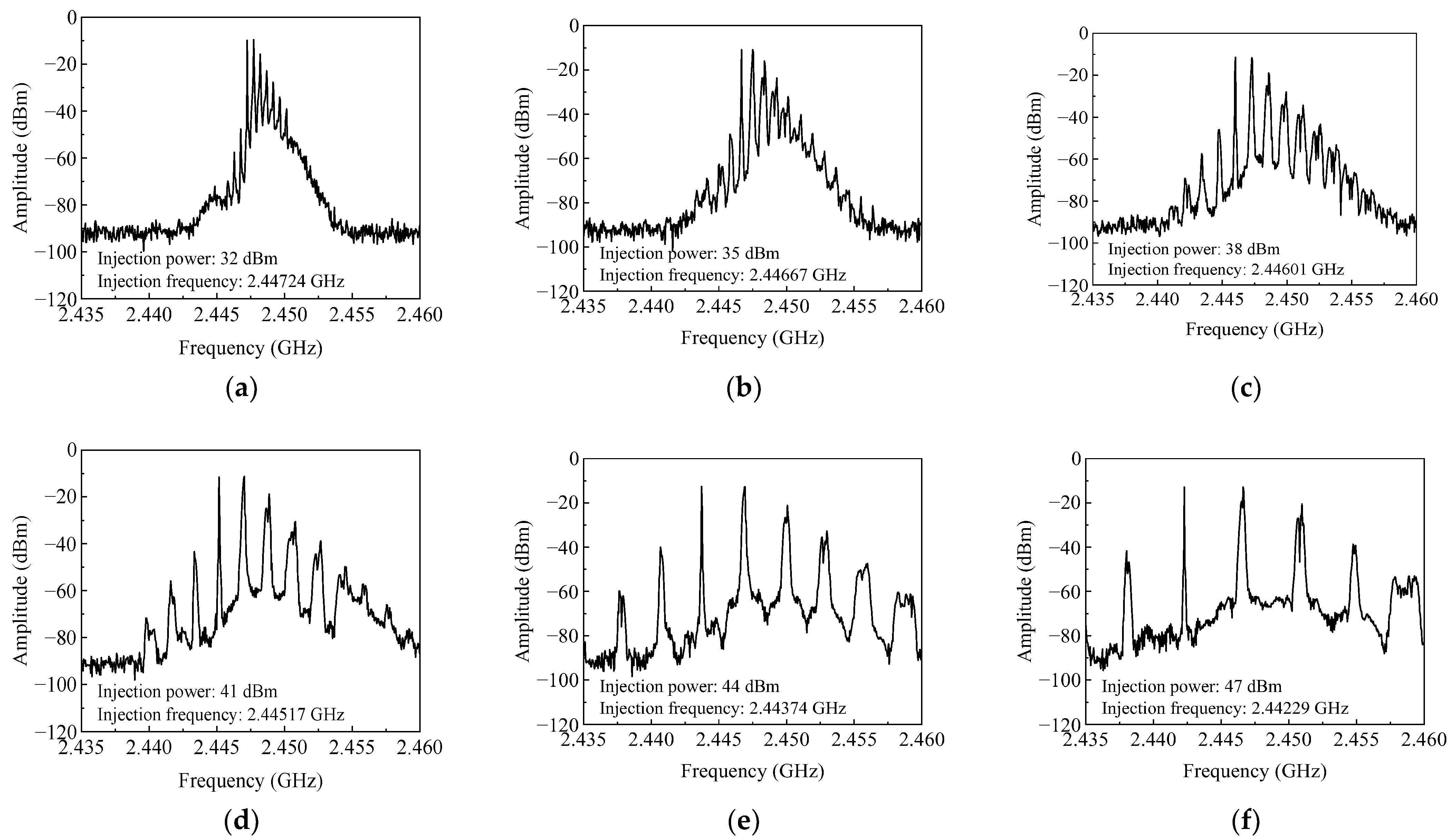
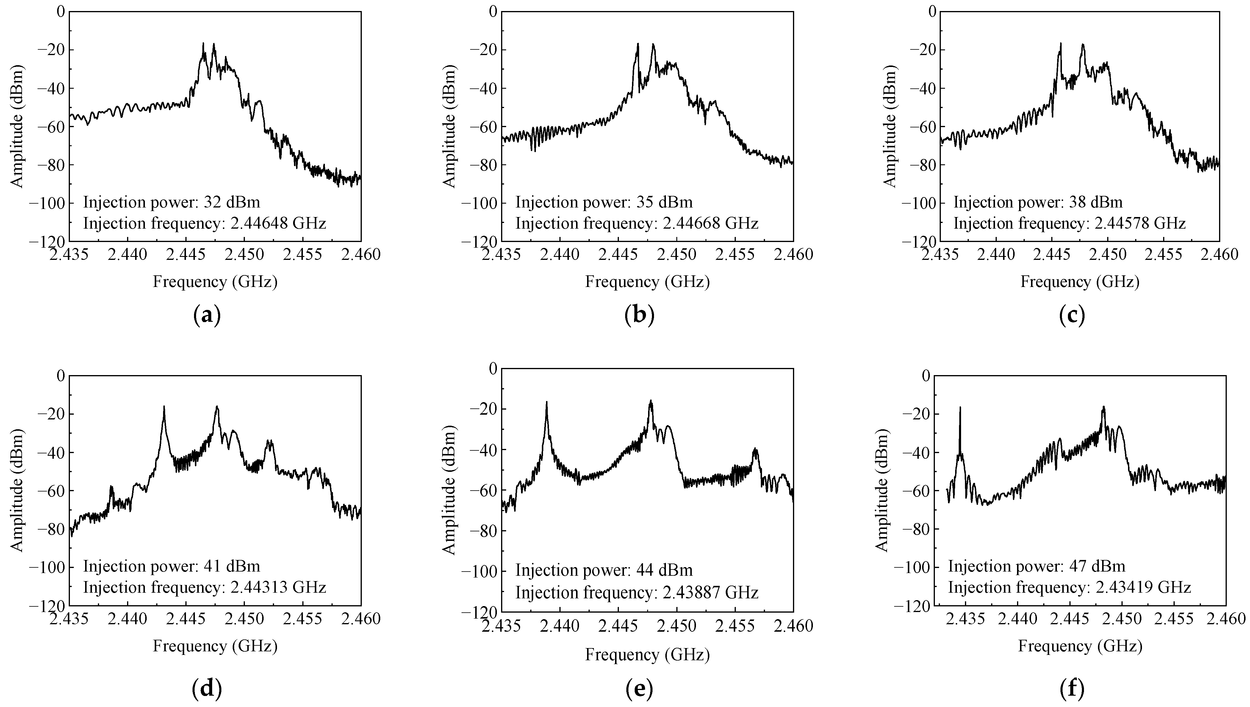
4. Results and Discussion

A series of contrasting experiments are conducted at the lower edge of the injection locking bandwidth. Different frequencies and power levels of injection signals are used to make the magnetron generate dual-frequency output. The output spectra are shown in Figure 5. The frequencies and corresponding normalized amplitudes of the two primary frequencies are labeled.
As shown in Figure 5, when the anode voltage ripple is 1.2%, the left peak frequencies and dual-frequency intervals are (f1, Δf), as (2447.24, 0.48 MHz), (2446.67 0.83 MHz), (2446.02, 1.26 MHz), (2445.16, 1.86 MHz), (2443.75, 3.21 MHz), and (2442.29, 4.34 MHz), respectively. f1 and f2 = f1 + Δf are the dual frequencies of microwave outputs.
To investigate the effects of anode voltage ripples on the output characteristics of quasi-dual frequency, the same experimental process is repeated using the original power supply with a 7% voltage ripple. The obtained spectra of dual-frequency output are shown in Figure 6, and the feasibility and tunability of generating quasi-dual-frequency signals are also reflected. The frequency intervals are 0.91 MHz, 1.26 MHz, 1.95 MHz, 4.53 MHz, 8.87 MHz, and 13.74 MHz, respectively. Compared with the previous results in Figure 5, the frequency intervals of dual-frequency outputs are more remarkable, and there is much less power distribution at other frequencies.
In the magnetron’s output spectra, the left power peaks’ frequencies match the injected signals’ frequencies. Furthermore, as the frequency of the injected signal approaches the edge of the locking bandwidth, the required injection power decreases significantly, and the magnetron’s output frequency interval becomes smaller. As the injection power increases, the power pulling of the injected signal on the magnetron becomes stronger, leading to a much greater frequency interval. It is proved that the frequency tunability of the dual-frequency microwave generator can be achieved by adjusting the frequency and power of the injected signal. The frequency interval of the magnetron output can also be tuned within a specific range. This is consistent with the results of numerical calculations.
The instantaneous output power of the magnetron during the experiments is measured using the power meter, and the results present that the magnetron’s output powers are nearly equal before and after adding the capacitor control module. Moreover, a numerical integration of the power spectral distributions is performed, as shown in Figure 5 and Figure 6. The results show that the numerical integration results at different voltage ripples are nearly identical under identical injection powers. This implies that the output power of the magnetron does not change with various anode voltage ripples. Thus, it is shown that changing the anode voltage ripples does not decrease the magnetron’s efficiency.
Table 1 compares the tunable frequency interval ranges of dual-frequency outputs under various voltage ripples. With the voltage ripple parameter increasing from 1.2% to 7%, the tuning range of frequency intervals increases from 0.48–4.34 MHz to 0.91–13.74 MHz as the injection power ratio ρ increases from 0.045 to 0.250. This suggests that by injecting an additional signal at the same power level, the tunable range of the quasi-dual-frequency output can be improved by increasing the anode voltage ripple. The difference in frequency intervals under two voltage ripples is up to 9.40 MHz, which indicates that the effects of voltage ripples become much more significant as the Injection power increases.
As seen in Table 2, the free-running magnetron’s central frequency and output power are almost equal under different voltage ripples. The quasi-dual-frequency output generated by the proposed method has a greater tunable range and a more obvious dual-frequency characteristic when the voltage ripple is higher. Meanwhile, the efficiency of the quasi-dual-frequency magnetron is not affected.
In principle, the free-running magnetrons distribute the power around a fixed operating frequency. However, a single frequency may not be suitable for microwave heating applications, due to poor heating uniformity. On the other hand, generating quasi-dual frequencies pulls more power to other frequencies by injecting an extra signal. As the injection frequency varies, the power distribution in the frequency domain is different. Distributing power at more frequencies is beneficial for improving heating performance. We will pursue further research on this method to address diverse heating needs and scenarios and conduct comprehensive studies to broaden its applications across various fields.

5. Conclusions

This paper presents a new method of using a single magnetron as a quasi-dual-frequency microwave generator. The method has several benefits, including simplicity of implementation, low system cost, controllability, and high output power.
A quasi-dual-frequency output with tunable dual-frequency frequency interval in the range of 0.48–13.74 MHz has been successfully realized through experiments. Moreover, the effects of magnetron anode voltage ripples on the quasi-dual-frequency output are verified, revealing that quasi-dual-frequency microwave outputs can be generated using this method with anode power supplies with different voltage ripples while maintaining the magnetron’s efficiency. The frequency interval of the dual-frequency output is observed to increase with higher voltage ripple levels.
This work has promising implications for improving microwave heating uniformity in industrial applications.

Author Contributions

Conceptualization, C.L. and S.W.; methodology, S.W., and Y.Z.; validation and writing—original draft, Y.Z.; writing—review and editing, Z.H. and C.L.; supervision, L.Y. and C.L. All authors have read and agreed to the published version of the manuscript.

Funding

This research is supported in part by the National Nature Science Foundation of China U22A2015 and 62071316.

Data Availability Statement

All relevant data have been presented in the article.

Conflicts of Interest

The authors declare no conflicts of interest.

References

  1. Gonzalez Rivera, J.; Pulidori, E.; Pelosi, C.; Ferrari, C.; Bernazzani, L.; Tinè, M.R.; Bramanti, E.; Duce, C. 20 Years of Microwave Technology Developments Using a Coaxial Antenna: From Human Health to Green Chemistry Applications. Curr. Res. Green Sustain. Chem. 2022, 5, 100337. [Google Scholar] [CrossRef]
  2. Ye, J.; Zhang, C.; Zhu, H. A Temperature-Control System for Continuous-Flow Microwave Heating Using a Magnetron as Microwave Source. IEEE Access 2020, 8, 44391–44399. [Google Scholar] [CrossRef]
  3. Ikenaga, K.; Inoue, T.; Kusakabe, K. Hydrolysis of PET by Combining Direct Microwave Heating with High Pressure. Procedia Eng. 2016, 148, 314–318. [Google Scholar] [CrossRef]
  4. Bae, S.-H.; Jeong, M.-G.; Kim, J.-H.; Lee, W.-S. A Continuous Power-Controlled Microwave Belt Drier Improving Heating Uniformity. IEEE Microw. Wirel. Compon. Lett. 2017, 27, 527–529. [Google Scholar] [CrossRef]
  5. Li, Z.Y.; Wang, R.F.; Kudra, T. Uniformity Issue in Microwave Drying. Dry. Technol. 2011, 29, 652–660. [Google Scholar] [CrossRef]
  6. Antonio, C.; Deam, R.T. Comparison of Linear and Non-Linear Sweep Rate Regimes in Variable Frequency Microwave Technique for Uniform Heating in Materials Processing. J. Mater. Process. Technol. 2005, 169, 234–241. [Google Scholar] [CrossRef]
  7. Du, Z.; Wu, Z.; Gan, W.; Liu, G.; Zhang, X.; Liu, J.; Zeng, B. Multi-Physics Modeling and Process Simulation for a Frequency-Shifted Solid-State Source Microwave Oven. IEEE Access 2019, 7, 184726–184733. [Google Scholar] [CrossRef]
  8. Ku, H.S.-L.; Yusaf, T. Processing of Composites Using Variable and Fixed Frequency Microwave Facilities. Prog. Electromagn. Res. B 2008, 5, 185–205. [Google Scholar] [CrossRef]
  9. Bows, J.R. Variable Frequency Microwave Heating of Food. J. Microw. Power Electromagn. Energy 1999, 34, 227–238. [Google Scholar] [CrossRef]
  10. Yakovlev, V.V. Frequency Control over the Heating Patterns in a Solid-State Dual-Source Microwave Oven. In Proceedings of the 2015 IEEE MTT-S International Microwave Symposium, Phoenix, AZ, USA, 17–22 May 2015; IEEE: Piscataway, NJ, USA, 2015; pp. 1–4. [Google Scholar] [CrossRef]
  11. Chen, X.; Yang, B.; Shinohara, N.; Liu, C. Low-Noise Dual-Way Magnetron Power-Combining System Using an Asymmetric H-Plane Tee and Closed-Loop Phase Compensation. IEEE Trans. Microw. Theory Techn. 2021, 69, 2267–2278. [Google Scholar] [CrossRef]
  12. Huang, H.; Yang, B.; Shinohara, N.; Liu, C. Coherent Power Combining of Four-Way Injection-Locked 5.8-GHz Magnetrons Based on a Five-Port Hybrid Waveguide Combiner. IEEE Trans. Microw. Theory Techn. 2024, 1–10. [Google Scholar] [CrossRef]
  13. Liu, Z.; Chen, X.; Yang, M.; Wu, P.; Huang, K.; Liu, C. Experimental Studies on a Four-Way Microwave Power Combining System Based on Hybrid Injection-Locked 20-kW S-Band Magnetrons. IEEE Trans. Plasma Sci. 2019, 47, 243–250. [Google Scholar] [CrossRef]
  14. Wang, S.; Shen, Y.; Liao, C.; Jing, J.; Liu, C. A Novel Injection-Locked S-Band Oven Magnetron System Without Waveguide Isolators. IEEE Trans. Electron Devices 2023, 70, 1886–1893. [Google Scholar] [CrossRef]
  15. Liu, C.; Wang, S.; Yan, L. Injection-Locked Magnetron System Based on Filament Injection. U.S. Patent No. 11,842,878, 12 December 2023. [Google Scholar]
  16. Yang, B.; Mitani, T.; Shinohara, N. Evaluation of the Modulation Performance of Injection-Locked Continuous-Wave Magnetrons. IEEE Trans. Electron Devices 2019, 66, 709–715. [Google Scholar] [CrossRef]
  17. Chen, X.; Yu, Z.; Lin, H.; Zhao, X.; Liu, C. Improvements in a 20-kW Phase-Locked Magnetron by Anode Voltage Ripple Suppression. IEEE Trans. Plasma Sci. 2020, 48, 1879–1885. [Google Scholar] [CrossRef]
  18. Ha, C.-S.; Kim, T.-H.; Jang, S.-R.; Kim, J.-S.; Han, S.-T. Experimental Study on the Effect of the Characteristics of a Switching-Mode Power Supply on a Phase-Locked Magnetron. IEEE Electron Device Lett. 2022, 43, 619–622. [Google Scholar] [CrossRef]
  19. Yang, F.; Wang, W.; Yan, B.; Hong, T.; Yang, Y.; Zhu, H.; Wu, L.; Huang, K. Sweep Frequency Heating Based on Injection Locked Magnetron. Processes 2019, 7, 341. [Google Scholar] [CrossRef]
  20. Du, M.; Zhang, Z.; Huang, J.; Zhu, H.; Yang, Y. Study of Multi-Frequency Heating Based on the Nonlinear Response Characteristics of Magnetron to Improve Uniformity. J. Microw. Power Electromagn. Energy 2023, 57, 71–88. [Google Scholar] [CrossRef]
  21. Slater, J.C. The phasing of magnetrons. In Research Laboratory of Electronics; MIT: Cambridge, MA, USA, 1947; Volume 35. [Google Scholar]
  22. Chen, S.C. Growth and Frequency Pushing Effects in Relativistic Magnetron Phase-Locking. IEEE Trans. Plasma Sci. 1990, 18, 570–576. [Google Scholar] [CrossRef]
  23. Wang, S.; Zhao, Y.; Chen, X.; Liu, C. A Novel Stability Improvement Method of S-Band Magnetron Systems Based on Its Anode Current Feature. IEEE Trans. Microw. Theory Techn. 2024, 1–10. [Google Scholar] [CrossRef]
  24. Adler, R. A Study of Locking Phenomena in Oscillators. Proc. IRE 1946, 34, 351–357. [Google Scholar] [CrossRef]
  25. Gourary, M.M.; Rusakov, S.G.; Ulyanov, S.L.; Zharov, M.M. Injection Locking/Pulling Analysis of Oscillators under Fractional Excitation Frequency. In Proceedings of the 2011 20th European Conference on Circuit Theory and Design (ECCTD), Linkoping, Sweden, 29–31 August 2011; IEEE: Piscataway, NJ, USA, 2011; pp. 524–527. [Google Scholar] [CrossRef]
  26. Hong, B.; Hajimiri, A. A General Theory of Injection Locking and Pulling in Electrical Oscillators—Part II: Amplitude Modulation in LC Oscillators, Transient Behavior, and Frequency Division. IEEE J. Solid-State Circuits 2019, 54, 2122–2139. [Google Scholar] [CrossRef]
  27. Brown, W.C.; Eves, E.E. Beamed Microwave Power Transmission and Its Application to Space. IEEE Trans. Microw. Theory Techn. 1992, 40, 1239–1250. [Google Scholar] [CrossRef]
  28. Wang, S.; Zhao, Y.; He, Z.; Lan, J.; Yan, L.; Liu, C. Experimental Study on Spurious Suppression Techniques of S-Band Magnetrons. In Proceedings of the 2023 IEEE 7th International Symposium on Electromagnetic Compatibility (ISEMC), Hangzhou, China, 20 October 2023; IEEE: Piscataway, NJ, USA, 2023; pp. 1–3. [Google Scholar]
  29. Tahir, I.; Dexter, A.; Carter, R. Noise Performance of Frequency- and Phase-Locked CW Magnetrons Operated as Current-Controlled Oscillators. IEEE Trans. Electron Devices 2005, 52, 2096–2103. [Google Scholar] [CrossRef]
Figure 1. Equivalent circuit of the magnetron with a load.
Electronics 13 01323 g001
Figure 2. Output spectrum of the injection-pulled magnetron by numerical calculation.
Electronics 13 01323 g002
Figure 3. Results of numerical calculations: Spectra of the quasi-dual-frequency microwave output with different injection intensities and frequencies. The normalized injection frequencies are labelled by arrows in Figure. The injection intensities are (a) 0.002, (b) 0.004, (c) 0.006, and (d) 0.008.
Electronics 13 01323 g003
Figure 4. (a) Block diagram and (b) photo of the experimental system. The names of the experimental instruments and devices in the figure are annotated with arrows.
Electronics 13 01323 g004
Figure 5. Measured spectra of the generated dual-frequency microwave output when the ripple parameter of anode voltage ripples is 1.2%. The injection powers are (a) 32 dBm, (b) 35 dBm, (c) 38 dBm, (d) 41 dBm, (e) 44 dBm, and (f) 47 dBm.
Electronics 13 01323 g005
Figure 6. Measured spectra of the generated dual-frequency microwave output when the ripple parameter of anode voltage ripples is 7%. The injection powers are (a) 32 dBm, (b) 35 dBm, (c) 38 dBm, (d) 41 dBm, (e) 44 dBm, and (f) 47 dBm.
Electronics 13 01323 g006
Table 1. Comparison of tunable frequency interval.
Injection Power (dBm)Injection Ratio ρFrequency Interval Δf (MHz)
1.2% Ripple7% Ripple
320.0450.480.91
350.0640.831.26
380.0901.261.95
410.1281.864.53
440.1783.218.87
470.2504.3413.74
Table 2. Comparison of results under different voltage ripples.
Injection Power:
32–47 dBm
Low Voltage RippleHigh Voltage Ripple
Voltage ripple Vp-p48 V280 V
Ripple parameter1.2%7.0%
Central frequency (GHz)2.448042.44805
Adjustable frequency interval (MHz)4.3413.74
Average power (W)790790
Free-running power (W)788790
Disclaimer/Publisher’s Note: The statements, opinions and data contained in all publications are solely those of the individual author(s) and contributor(s) and not of MDPI and/or the editor(s). MDPI and/or the editor(s) disclaim responsibility for any injury to people or property resulting from any ideas, methods, instructions or products referred to in the content.

