Broadband Beam-Scanning Phased Array Based on Microwave Photonics
Abstract
1. Introduction
2. Configuration and Working Mechanism
2.1. Configuration and Mechanism of the Antenna and TR Module
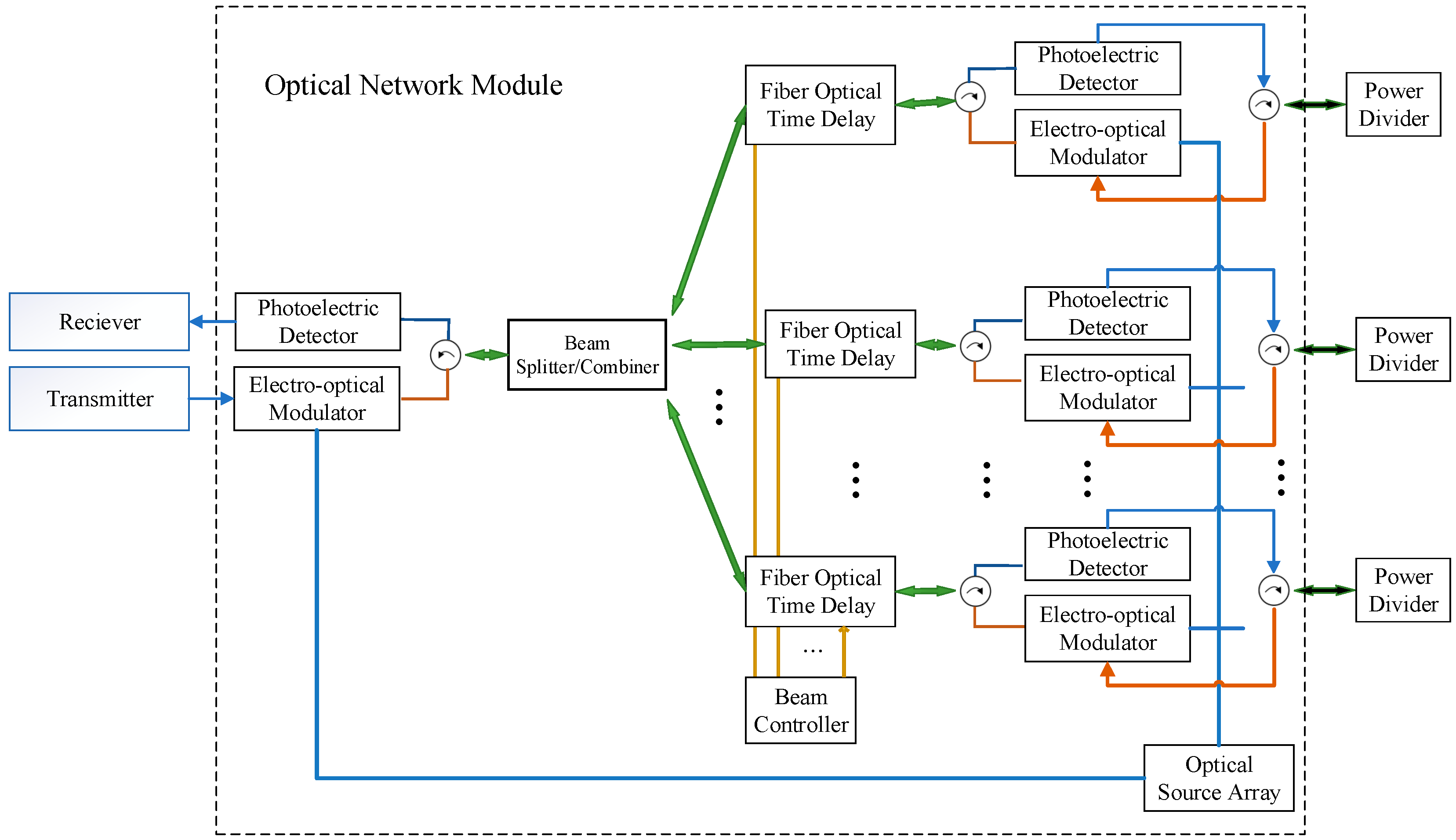
2.2. Configuration and Mechanism of the Optical Network Module
3. Simulated and Measured Results
4. Conclusions
Author Contributions
Funding
Data Availability Statement
Conflicts of Interest
References
- Parker, D.; Zimmermann, D.C. Phased arrays—Part 1: Theory and architectures. IEEE Trans. Microw. Theory Tech. 2002, 50, 678–687. [Google Scholar] [CrossRef]
- Parker, D.; Zimmermann, D.C. Phased arrays-part II: Implementations, applications, and future trends. IEEE Trans. Microw. Theory Tech. 2002, 50, 688–698. [Google Scholar] [CrossRef]
- Hansen, R.C. Phased Array Antennas; John Wiley & Sons: Hoboken, NJ, USA, 2009. [Google Scholar]
- Fenn, A.J.; Hurst, P.T. Ultrawideband Phased Array Antenna Technology for Sensing and Communications Systems; MIT Press: Cambridge, MA, USA, 2015. [Google Scholar]
- Yang, G.; Li, J.; Wei, D.; Xu, R. Study on wide-angle scanning linear phased array antenna. IEEE Trans. Antennas Propag. 2018, 66, 450–455. [Google Scholar] [CrossRef]
- Han, G.; Du, B.; Wu, W.; Yang, B. A novel hybrid phased array antenna for satellite communication on-the-move in Ku-band. IEEE Trans. Antennas Propag. 2015, 63, 1375–1383. [Google Scholar] [CrossRef]
- Hashemi, H.; Xiang, G.; Komijani, A.; Hajimiri, A. A 24-Ghz Sige phased-array receiver-LO phase-shifting approach. IEEE Trans. Microw. Theory Tech. 2005, 53, 614–626. [Google Scholar] [CrossRef]
- Zihir, S.; Gurbuz, O.D.; Kar-Roy, A.; Raman, S.; Rebeiz, G.M. 60-ghz 64- and 256-elements wafer-scale phased-array transmitters using full-reticle and subreticle stitching techniques. IEEE Trans. Microw. Theory Tech. 2016, 64, 4701–4719. [Google Scholar] [CrossRef]
- Kibaroglu, K.; Sayginer, M.; Phelps, T.; Rebeiz, G.M. A 64-element 28-ghz phased-array transceiver with 52-dBm eirp and 8–12-Gb/s 5G link at 300 meters without any calibration. IEEE Trans. Microw. Theory Tech. 2018, 66, 5796–5811. [Google Scholar] [CrossRef]
- Ku, B.H.; Schmalenberg, P.; Inac, O.; Gurbuz, O.D.; Lee, J.S.; Shiozaki, K.; Rebeiz, G.M. A 77–81-ghz 16-element phased-array receiver ±50º beam scanning for advanced automotive radars. IEEE Trans. Microw. Theory Tech. 2014, 62, 2823–2832. [Google Scholar] [CrossRef]
- Zhang, H.; Yang, S.; Chen, Y.; Guo, J.; Nie, Z. Wideband dual-polarized linear array of tightly coupled elements. IEEE Trans. Antennas Propag. 2018, 66, 476–480. [Google Scholar] [CrossRef]
- Zhang, H.; Yang, S.; Xiao, S.; Chen, Y.; Qu, S. Low-profile, lightweight, ultra-wideband tightly coupled dipole arrays loaded with split rings. IEEE Trans. Antennas Propag. 2019, 67, 4257–4262. [Google Scholar] [CrossRef]
- Zhang, L.; Gao, S.; Luo, Q.; Li, W.; He, Y.; Li, Q. A wideband circularly polarized tightly coupled array. IEEE Trans. Antennas Propag. 2018, 66, 6382–6387. [Google Scholar] [CrossRef]
- Wu, W.; Yan, Y.; Wang, S.; Ma, Y.; Yuan, N. An ultrathin Low-profile tightly coupled dipole array fed by compact zigzagging baluns. Electronics 2023, 12, 2752. [Google Scholar] [CrossRef]
- Li, W.; Qiu, T.; Wang, J.; Zheng, L.; Jing, Y.; Jia, Y.; Wang, H.; Han, Y.; Qu, S. Programmable coding metasurface reflector for reconfigurable multibeam antenna application. IEEE Trans. Antennas Propag. 2021, 69, 296–301. [Google Scholar] [CrossRef]
- Zhang, N.; Chen, K.; Zhao, J.; Hu, Q.; Tang, K.; Zhao, J.; Jiang, T.; Feng, Y. A dual-polarized reconfigurable reflectarray antenna based on dual-channel programmable metasurface. IEEE Trans. Antennas Propag. 2022, 70, 7403–7412. [Google Scholar] [CrossRef]
- Li, P.; Ren, J.; Chen, Y.; Ren, X.; Xu, K.D.; Yin, Y.Z.; Shen, M. Design of low-cost single-layer 2-bit reflective programmable metasurface based on folded ground. IEEE Trans. Microw. Theory Tech. 2023, 71, 3455–3465. [Google Scholar] [CrossRef]
- Lee, J.-G.; Lee, J.-H. Low-profile high-efficiency transmitarray antenna for beamforming applications. Electronics 2023, 12, 3178. [Google Scholar] [CrossRef]
- Teodorani, L.; Vernì, F.; Giordanengo, G.; Gaffoglio, R.; Vecchi, G. experimental demonstration of beam scanning of dual-metasurface antenna. Electronics 2023, 12, 1833. [Google Scholar] [CrossRef]
- Esteban Eraso, U.; Sánchez-Azqueta, C.; Aldea, C.; Celma, S. A 19.5 ghz 5-bit digitally programmable phase shifter for active antenna arrays. Electronics 2023, 12, 2862. [Google Scholar] [CrossRef]
- Bai, Y.Y.; Xiao, S.; Liu, C.; Wang, B.Z. A hybrid IWO/PSO algorithm for pattern synthesis of conformal phased arrays. IEEE Trans. Antennas Propag. 2013, 61, 2328–2332. [Google Scholar] [CrossRef]
- Bray, M.G.; Werner, D.H.; Boeringer, D.W.; Machuga, D.W. Optimization of thinned aperiodic linear phased arrays using genetic algorithms to reduce grating lobes during scanning. IEEE Trans. Antennas Propag. 2002, 50, 1732–1742. [Google Scholar] [CrossRef]
- Villegas, F.J. Parallel genetic-algorithm optimization of shaped beam coverage areas using planar 2-D phased arrays. IEEE Trans. Antennas Propag. 2007, 55, 1745–1753. [Google Scholar] [CrossRef]
- Boeringer, D.W.; Werner, D.H. Particle swarm optimization versus genetic algorithms for phased array synthesis. IEEE Trans. Antennas Propag. 2004, 52, 771–779. [Google Scholar] [CrossRef]
- Munson, R. Conformal microstrip antennas and microstrip phased arrays. IEEE Trans. Antennas Propag. 1974, 22, 74–78. [Google Scholar] [CrossRef]
- Daly, M.P.; Bernhard, J.T. Directional modulation technique for phased arrays. IEEE Trans. Antennas Propag. 2009, 57, 2633–2640. [Google Scholar] [CrossRef]
- Valavan, S.E.; Tran, D.; Yarovoy, A.G.; Roederer, A.G. Planar dual-band wide-scan phased array in X-band. IEEE Trans. Antennas Propag. 2014, 62, 5370–5375. [Google Scholar] [CrossRef]
- Wang, R.; Wang, B.Z.; Ding, X.; Yang, X.S. Planar phased array with Wide-angle scanning performance based on image theory. IEEE Trans. Antennas Propag. 2015, 63, 3908–3917. [Google Scholar] [CrossRef]
- Liu, C.M.; Xiao, S.Q.; Tu, H.L.; Ding, Z. Wide-angle scanning low profile phased array antenna based on a novel magnetic dipole. IEEE Trans. Antennas Propag. 2017, 65, 1151–1162. [Google Scholar] [CrossRef]
- Bai, Y.Y.; Xiao, S.; Tang, M.C.; Ding, Z.F.; Wang, B.Z. Wide-angle scanning phased array with pattern reconfigurable elements. IEEE Trans. Antennas Propag. 2011, 59, 4071–4076. [Google Scholar] [CrossRef]
- Moon, S.M.; Yun, S.; Yom, I.B.; Lee, H.L. Phased array shaped-beam satellite antenna with boosted-beam control. IEEE Trans. Antennas Propag. 2019, 67, 7633–7636. [Google Scholar] [CrossRef]
- Ding, Y.R.; Cheng, Y.J.; Sun, J.X.; Wang, L.; Li, T.J. Dual-band shared-aperture two-dimensional phased array antenna with wide bandwidth of 25.0% and 11.4% at ku- and ka-band. IEEE Trans. Antennas Propag. 2022, 70, 7468–7477. [Google Scholar] [CrossRef]
- Pan, S.; Zhang, Y. Microwave photonic radars. J. Light. Technol. 2020, 38, 5450–5484. [Google Scholar] [CrossRef]
- Pan, S.; Ye, X.; Zhang, Y.; Zhang, F. Microwave photonic array radars. IEEE J. Microw. 2021, 1, 176–190. [Google Scholar] [CrossRef]
- Attygalle, M.; Stepanov, D. Photonic technique for phase control of microwave to terahertz signals. IEEE Trans. Microw. Theory Tech. 2014, 62, 1381–1386. [Google Scholar] [CrossRef]
- Tang, Z.; Pan, S. A reconfigurable photonic microwave mixer using a 90° optical hybrid. IEEE Trans. Microw. Theory Tech. 2016, 64, 3017–3025. [Google Scholar] [CrossRef]
- Tulchinsky, D.A.; Matthews, P.J. Ultrawide-band fiber-optic control of a millimeter-wave transmit beamformer. IEEE Trans. Microw. Theory Tech. 2001, 49, 1248–1253. [Google Scholar] [CrossRef]
- Yu, Y.; Shang, Q.; An, S.; Zhang, Y.; Su, Y.; Yao, J. Tunable silicon photonic RF phase shifter with low RF power variation based on constructive interference of an add-drop ring resonator. IEEE Photonics J. 2018, 10, 1–8. [Google Scholar] [CrossRef]
- Zhang, Y.; Pan, S. Broadband microwave signal processing enabled by polarization-based photonic microwave phase shifters. IEEE J. Quantum Electron. 2018, 54, 1–12. [Google Scholar] [CrossRef]
- Zhou, P.; Zhang, F.; Pan, S. Generation of linear frequency-modulated waveforms by a frequency-sweeping optoelectronic oscillator. J. Light. Technol. 2018, 36, 3927–3934. [Google Scholar] [CrossRef]
- Wang, M.; Yao, J. Tunable 360° photonic radio-frequency phase shifter based on polarization modulation and all-optical differentiation. J. Light. Technol. 2013, 31, 2584–2589. [Google Scholar] [CrossRef]
- Zhang, X.; Hosseini, A.; Lin, X.; Subbaraman, H.; Chen, R.T. Polymer-based hybrid-integrated photonic devices for silicon on-chip modulation and board-level optical interconnects. IEEE J. Sel. Top. Quantum Electron. 2013, 19, 196–210. [Google Scholar] [CrossRef]
- Bui, L.A.; Mitchell, A.; Ghorbani, K.; Chio, T.-H.; Mansoori, S.; Lopez, E.R. Wide-band photonically phased array antenna using vector sum phase shifting approach. IEEE Trans. Antennas Propag. 2005, 53, 3589–3596. [Google Scholar] [CrossRef][Green Version]
- McKenna, T.P.; Nanzer, J.A.; Clark, T.R. Photonic beamsteering of a millimeter-wave array with 10-Gb/s data transmission. IEEE Photonics Technol. Lett. 2014, 26, 1407–1410. [Google Scholar] [CrossRef]
- Meijerink, A.; Roeloffzen, C.G.H.; Meijerink, R.; Zhuang, L.; Marpaung, D.A.I.; Bentum, M.J.; Burla, M.; Verpoorte, J.; Jorna, P.; Hulzinga, A.; et al. Novel ring resonator-based integrated photonic beamformer for broadband phased array receive antennas—Part I: Design and performance analysis. J. Light. Technol. 2010, 28, 3–18. [Google Scholar] [CrossRef]
- Zhuang, L.; Roeloffzen, C.G.H.; Meijerink, A.; Burla, M.; Marpaung, D.A.I.; Leinse, A.; Hoekman, M.; Heideman, R.G.; Etten, W.V. Novel ring resonator-based integrated photonic beamformer for broadband phased array receive antennas—Part II: Experimental prototype. J. Light. Technol. 2010, 28, 19–31. [Google Scholar] [CrossRef]
- Tsokos, C.; Andrianopoulos, E.; Raptakis, A.; Lyras, N.K.; Gounaridis, L.; Groumas, P.; Timens, R.B.; Visscher, I.; Grootjans, R.; Wefers, L.S.; et al. True time delay optical beamforming network based on hybrid inp-silicon nitride integration. J. Light. Technol. 2021, 39, 5845–5854. [Google Scholar] [CrossRef]
- Zheng, P.; Wang, C.; Xu, X.; Li, J.; Lin, D.; Hu, G.; Zhang, R.; Yun, B.; Cui, Y. A seven bit silicon optical true time delay line for ka-band phased array antenna. IEEE Photonics J. 2019, 11, 1–9. [Google Scholar] [CrossRef]
- Paula, I.L.d.; Bogaert, L.; Caytan, O.; Kerrebrouck, J.V.; Moerman, A.; Muneeb, M.; Brande, Q.V.d.; Torfs, G.; Bauwelinck, J.; Rogier, H.; et al. Air-filled SIW remote antenna unit with true time delay optical beamforming for mmWave-Over-fiber systems. J. Light. Technol. 2022, 40, 6961–6975. [Google Scholar] [CrossRef]
- Carey, V.A.; Konkol, M.R.; Shi, S.; Mercante, A.J.; Shreve, K.; Wright, A.A.; Schuetz, C.A.; Prather, D.W. Millimeter wave photonic tightly coupled array. IEEE Trans. Antennas Propag. 2021, 69, 4488–4503. [Google Scholar] [CrossRef]
- Ross, D.D.; Konkol, M.R.; Shi, S.; Harrity, C.E.; Wright, A.A.; Schuetz, C.A.; Prather, D.W. Low-profile high-power optically addressed phased array antenna. J. Light. Technol. 2017, 35, 3894–3900. [Google Scholar] [CrossRef]
- Shi, S.; Bai, J.; Schneider, G.J.; Zhang, Y.; Nelson, R.; Wilson, J.; Schuetz, C.; Grund, D.W.; Prather, D.W. Conformal wideband optically addressed transmitting phased array with photonic receiver. J. Light. Technol. 2014, 32, 3468–3477. [Google Scholar] [CrossRef]


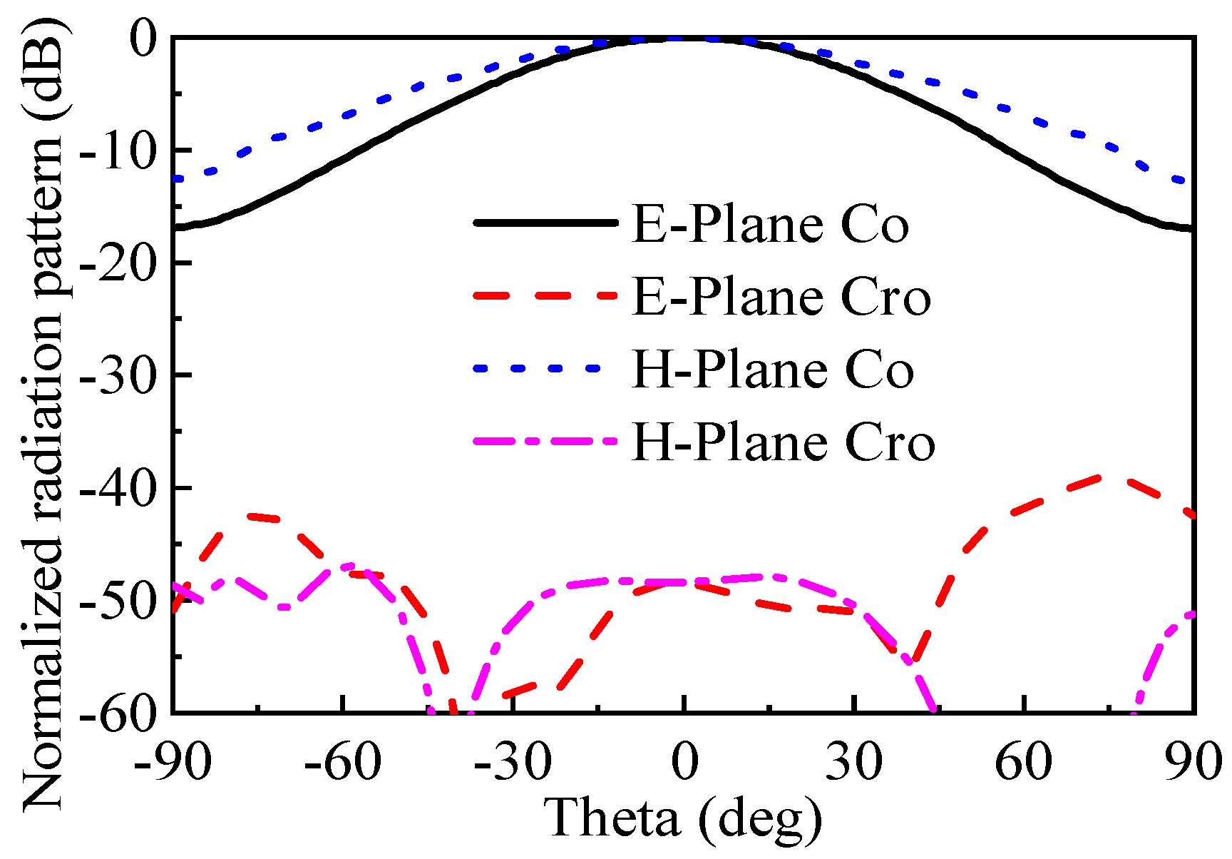
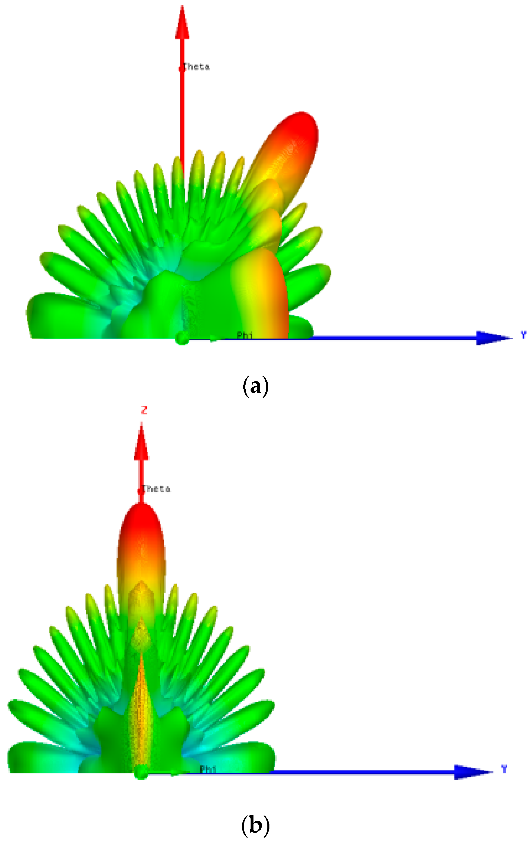
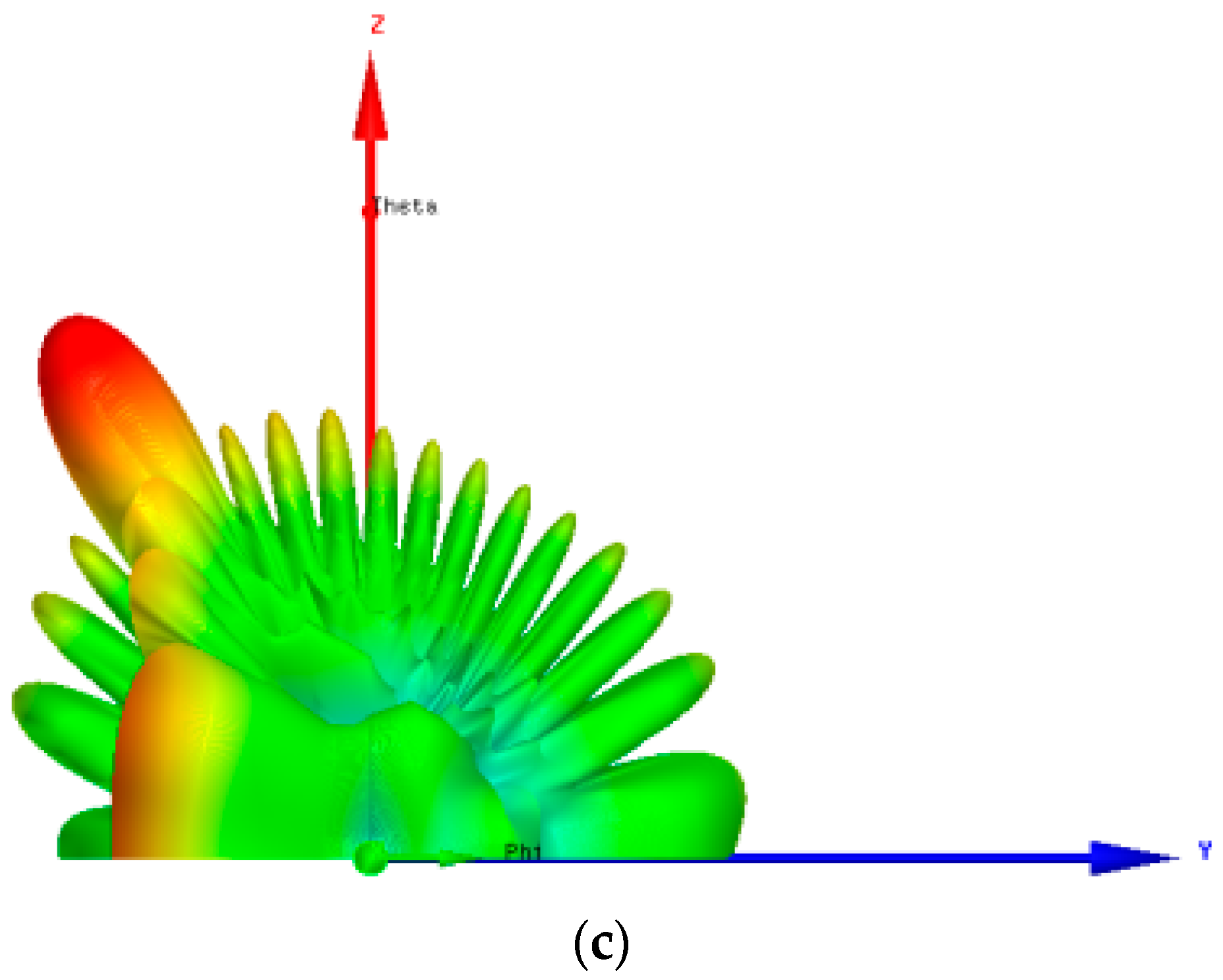




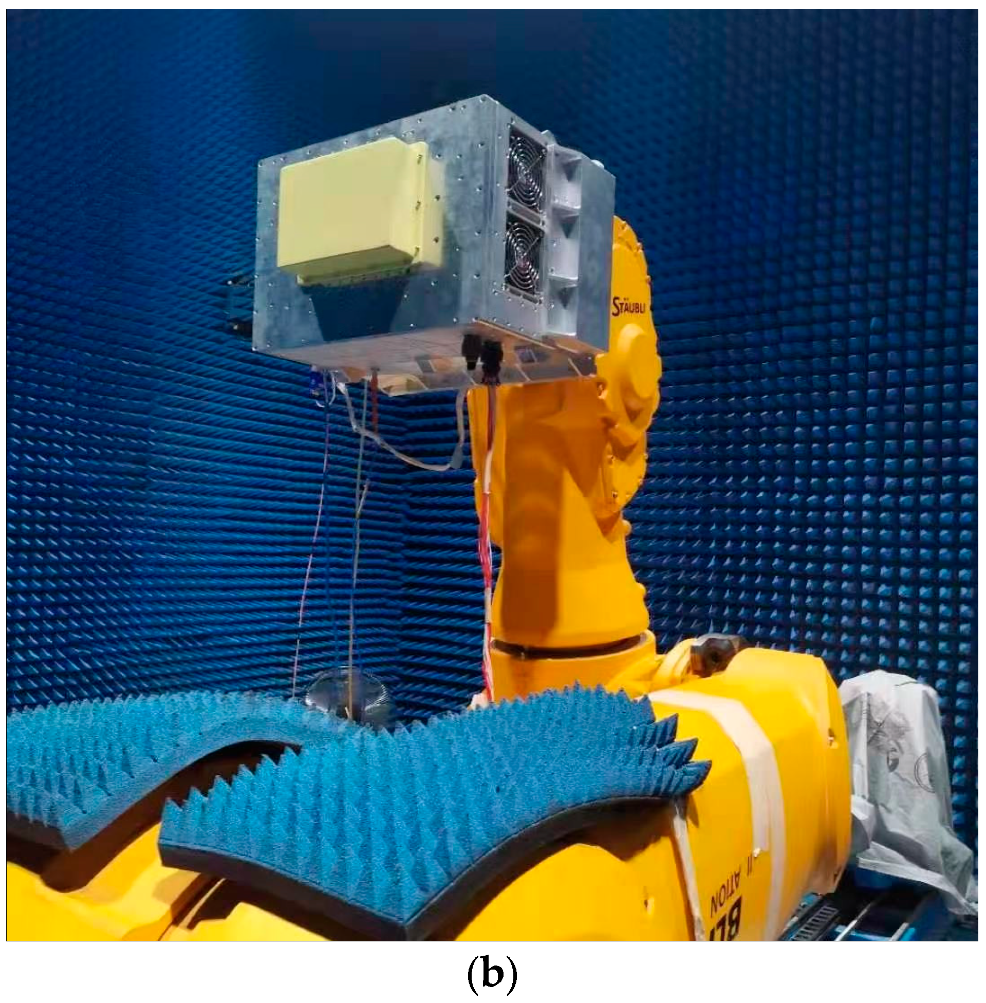
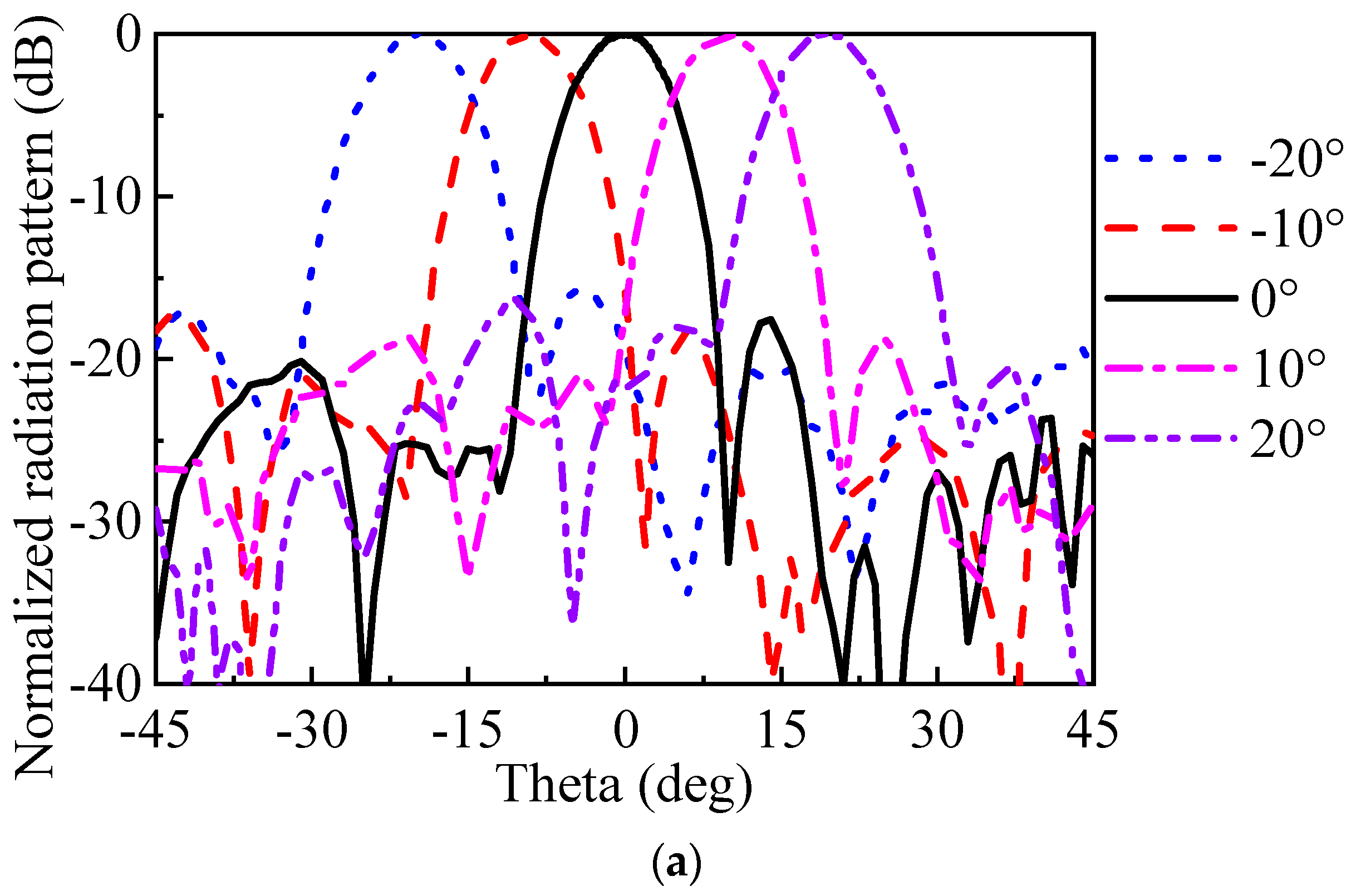
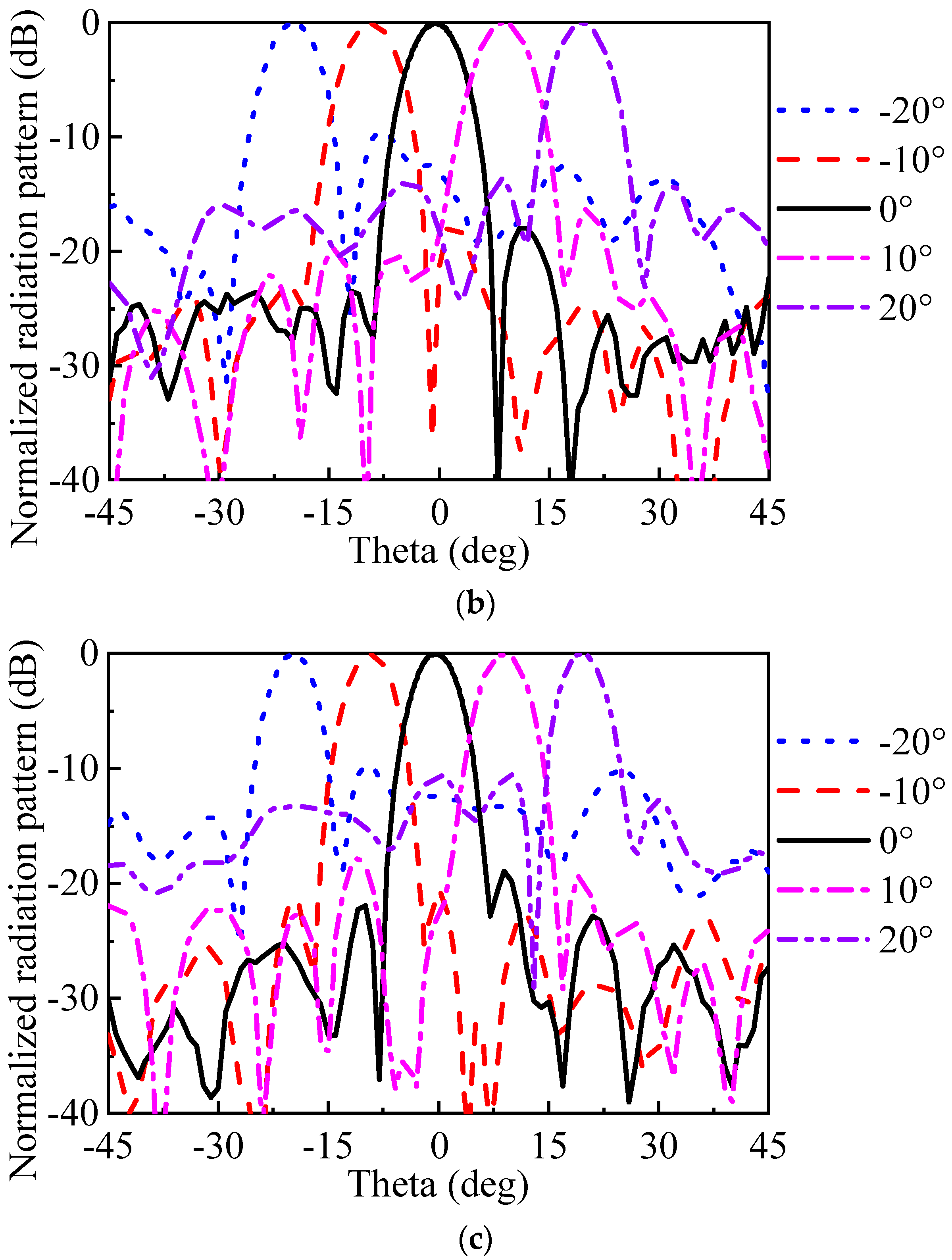
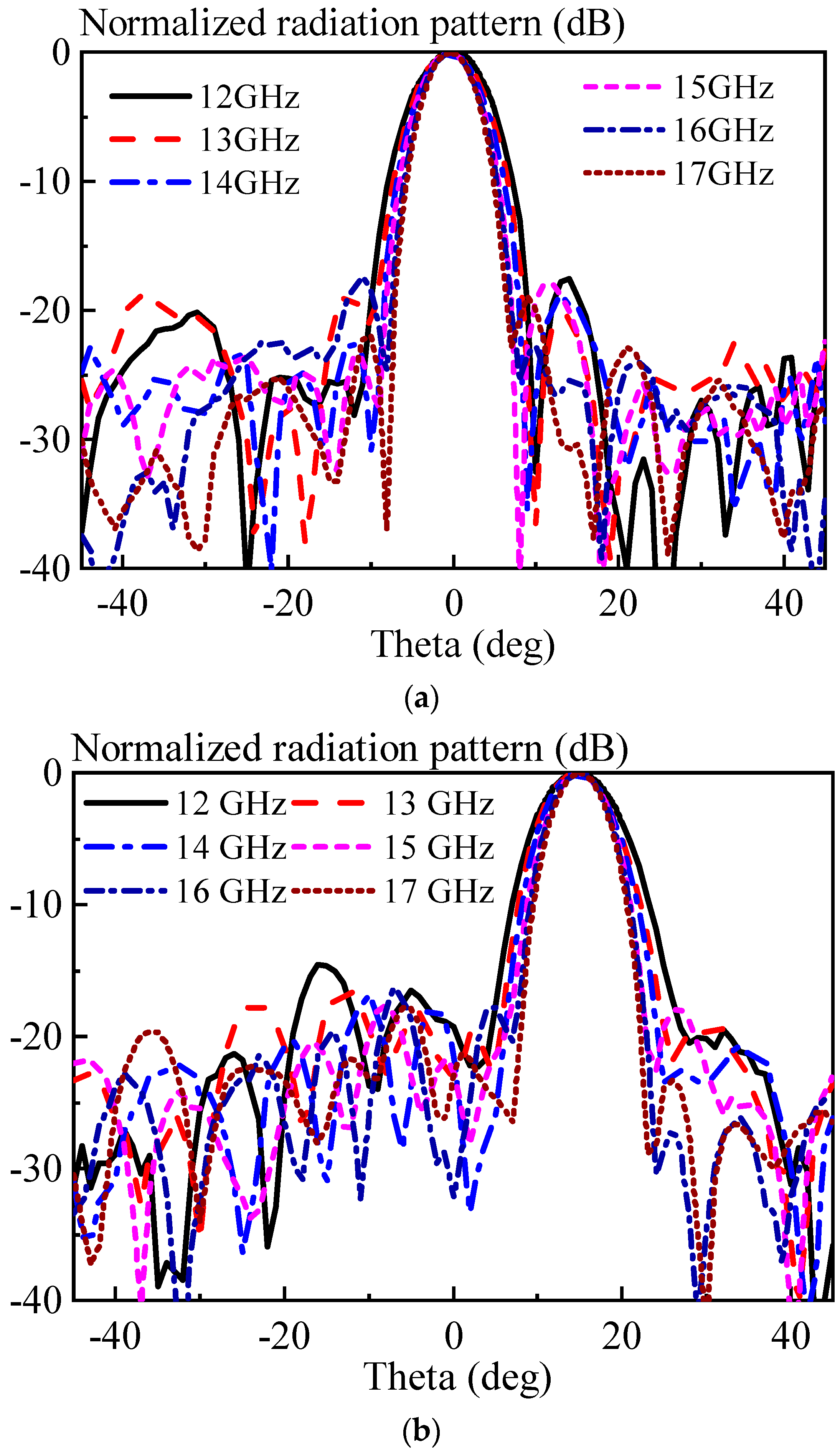
| Temperature Degree | Channel 1 | Channel 2 | Channel 3 | Channel 4 |
|---|---|---|---|---|
| −10° | 65 | 64.4 | 65.6 | 66.9 |
| 0° | 65.6 | 64.4 | 65 | 66.3 |
| 10° | 65 | 63.8 | 65.6 | 66.3 |
| 20° | 65 | 64.4 | 65.6 | 66.3 |
| 30° | 65 | 65 | 65.6 | 66.9 |
| Ref. | Operating Band (GHz) | BW (%) | Scanning Angle | No. of Elements | Antenna Type | Temperature Control | PQ |
|---|---|---|---|---|---|---|---|
| [43] | 10–14 | 33.3 | ±30° | 16 (4 × 4) | Vivaldi antenna | No | NM |
| [44] | 85–91 | 6.8 | ±35° | NM | NM | No | 4 bit |
| [51] | 6–17 | 95.6 | ±30° | 8 (1 × 8) | Dipole antenna | No | NM |
| [52] | 34–38 | 11.1 | ±40° | 16 (4 × 4) | Patch antenna | No | NM |
| This work | 12–17 | 34.3 | ±30° | 16 (1 × 16) | Horn antenna | Yes | 9 bit |
Disclaimer/Publisher’s Note: The statements, opinions and data contained in all publications are solely those of the individual author(s) and contributor(s) and not of MDPI and/or the editor(s). MDPI and/or the editor(s) disclaim responsibility for any injury to people or property resulting from any ideas, methods, instructions or products referred to in the content. |
© 2024 by the authors. Licensee MDPI, Basel, Switzerland. This article is an open access article distributed under the terms and conditions of the Creative Commons Attribution (CC BY) license (https://creativecommons.org/licenses/by/4.0/).
Share and Cite
Luan, Y.; Yang, T.; Ren, J.; Li, R.; Zhang, Z. Broadband Beam-Scanning Phased Array Based on Microwave Photonics. Electronics 2024, 13, 1278. https://doi.org/10.3390/electronics13071278
Luan Y, Yang T, Ren J, Li R, Zhang Z. Broadband Beam-Scanning Phased Array Based on Microwave Photonics. Electronics. 2024; 13(7):1278. https://doi.org/10.3390/electronics13071278
Chicago/Turabian StyleLuan, Yuchen, Tian Yang, Jian Ren, Ruoming Li, and Zhuo Zhang. 2024. "Broadband Beam-Scanning Phased Array Based on Microwave Photonics" Electronics 13, no. 7: 1278. https://doi.org/10.3390/electronics13071278
APA StyleLuan, Y., Yang, T., Ren, J., Li, R., & Zhang, Z. (2024). Broadband Beam-Scanning Phased Array Based on Microwave Photonics. Electronics, 13(7), 1278. https://doi.org/10.3390/electronics13071278


