1. Introduction
With the rapid proliferation of inverter-based resources (IBRs) globally, the utilization of thermal power plants is poised for a decline. While IBRs may not match synchronous generation in all operational aspects, their integration with a consistent source, such as a battery energy storage system (BESS), enables them to offer frequency regulation, increased system inertia, and superior voltage and frequency ride-through capabilities compared to synchronous generation [
1]. The diminishing availability of fault currents may give rise to prevalent weak grid issues, resulting in broader disturbances than previously observed. Weak grid issues encompass voltage instability, harmonic resonance, sub-synchronous oscillations, voltage flicker, and other stability challenges [
2].
The most significant impact can be attributed to the reduction in the short-circuit current in IBR-dominated grids, as fault currents are now supplied by IBRs. In comparison to synchronous machines, which typically provide 5–8 per unit (p.u.), the short-circuit current of inverters is considerably smaller. A manifestation of low system strength revolves around compromising system stability. Historical consensus on IBRs points to their inability to handle network faults, resulting in small oscillatory behaviors and post-disturbance recovery. Fault currents generated by conventional generators are influenced to some extent by the impedance between the generator terminal and the fault location. In contrast, fault currents from inverters, commonly regulated by the current, exhibit minimal to no dependency on network impedance. Conventional protection studies often overlook the short-circuit response of IBRs. Their current limiter significantly influences the steady-state fault current, while the inverter filter and voltage disturbance severity largely dictate the initial transient spike in the fault current [
3,
4,
5]. This reduction may desensitize protection settings, causing delays in protection operation times or even lowering the sensed current to below the minimum relay sensing values, rendering them ineffective–even in distance relays, the mainstream transmission line protection scheme. This is characterized by the researchers of [
6,
7,
8] and the references therein. References [
6,
7] provide a comprehensive overview of these challenges, with a focus on the transmission system and utilizing IEEE test systems. The authors of [
8], conversely, provide a comprehensive overview of the impact of IBRs on overcurrent protection, which is a scheme used primarily in distribution systems but also as a backup scheme in transmission systems.
The Puerto Rico grid comprises a transmission network with voltages of 115 kV and 230 kV, along with a subtransmission system at 38 kV. Puerto Rico’s legislation mandates a transition to a 40% renewable energy mix by 2025 and complete reliance on 100% renewable energy by 2050 [
2]. In the short term, grid strength is anticipated to significantly decrease, with photovoltaic (PV) systems exhibiting capacity factors of around 20% in this region. Consequently, the system is expected to experience 100% instantaneous IBR generation in the very short term, necessitating rapid investments in the grid infrastructure, the specifics of which need to be comprehensively understood.
A prior study [
9] in Puerto Rico assessed the potential short-circuit reduction, focusing on replacing the entire existing generation fleet with IBRs of the same rating. The authors concluded that certain segments of the 230 kV backbone could experience reductions in total three-phase short-circuit levels exceeding 60%. However, this analysis was limited to the total three-phase short-circuit levels (SCMVA) of system buses, and no direct impact on protective relaying was quantified. Building upon this previous work, the authors propose extending the analysis to line currents for both three-phase and single-line-to-ground (SLG) faults at the midpoint of the line to directly understand the impact on protective relays and quantify their sensitivity to reduced fault flows. Although distance protection, which is the mainstream line protection scheme in most lines (followed by current line differential), is not affected by short-circuit reductions from the source standpoint, its microprocessor-based relays necessitate minimum current sensing to effectively detect through faults, typically around 0.5 A at the relay terminal block. With high CT ratios, such as 2000:5, these reductions in short-circuit levels may pose challenges, suggesting the potential need for numerous upgrades.
A consensus among researchers is that a decrease in system strength can hinder fault detection, but adjustments such as modifying settings or replacing electromechanical relays with microprocessor-based counterparts can help mitigate this impact. If these improvements are not sufficient, the protection philosophy may need to be modified, for instance, by replacing line distance protection with line current differential protection schemes. Our paper’s key discovery is that, despite short-circuit levels dropping by up to 80% in certain grid regions, current protection philosophies remain effective for foreseeable scenarios, necessitating only setting adjustments. To further this work, the authors also identify, size, and allocate synchronous condensers and static synchronous compensators (STATCOMs) to quantify their contribution to increasing fault currents flowing through line breakers during faults and determine how they can generally strengthen the grid. The authors would like to emphasize that this research only analyzed fault current levels and did not address stability or dynamic issues. These need to be addressed as well.
2. IBR Sequence Networks and Impact on Short-Circuit Levels
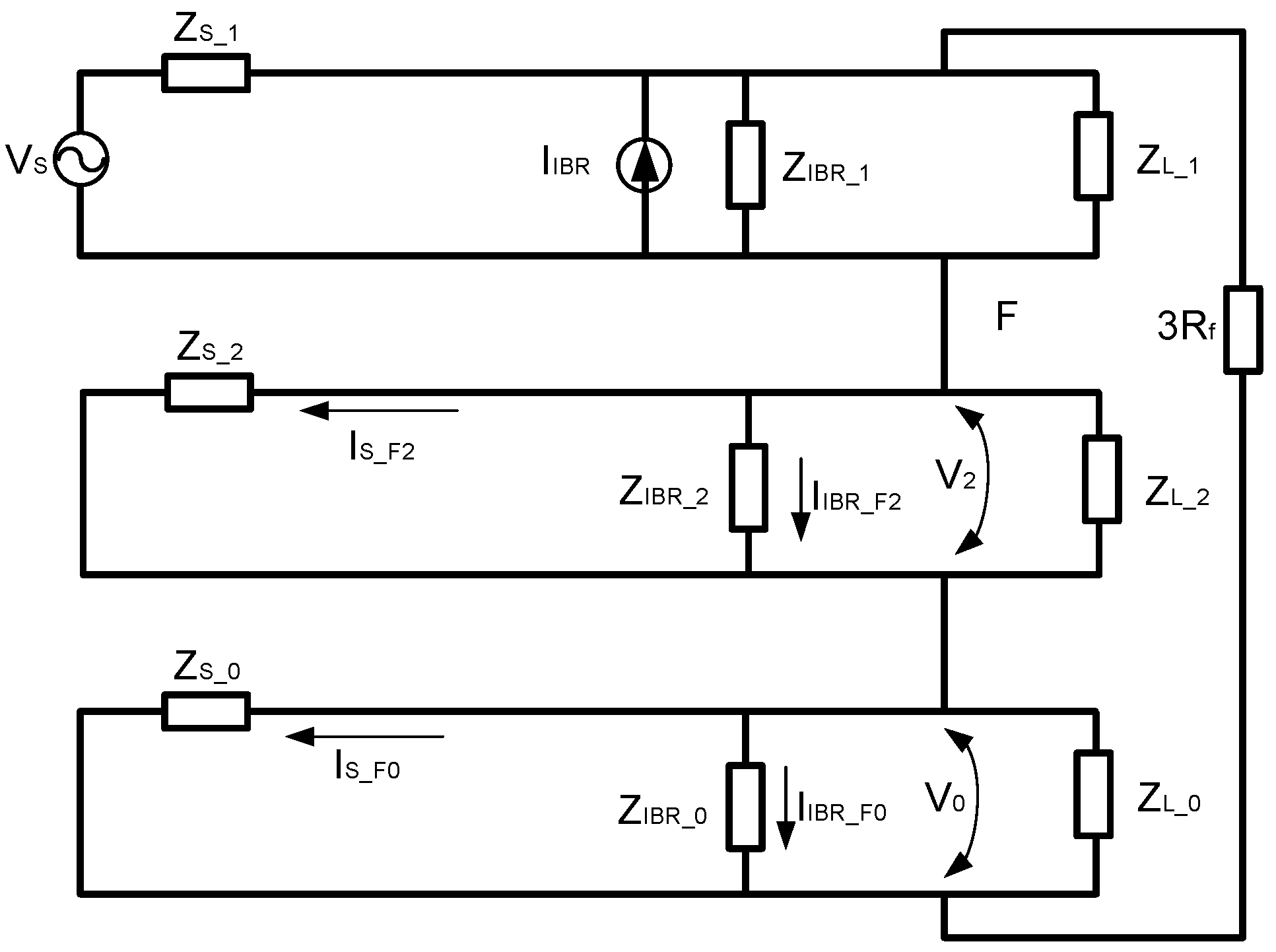
The design and functionality of inverter-based resources (IBRs) are rooted in the Voltage Source Converter (VSC) topology. Despite this foundation, adherence to grid codes necessitates their operation as constant current sources. This alignment with constant current behavior is imperative for facilitating voltage regulation and ensuring optimal controllability for system operators. Consequently, IBRs are conventionally modeled and represented as current sources within the power system framework. When analyzing a conventional power system integrated with an IBR and exposed to a ground fault characterized by impedance
Rf, a comprehensive depiction is required, as illustrated in
Figure 1. The power system under consideration receives its supply from an equivalent source (S) situated in a substation, caters to a designated load (L), and is interconnected with the IBR. Subscripts 0, 1, and 2 are employed to denote the zero-, positive-, and negative-sequence networks, contributing to a representation of the system dynamics. This representation enhances our comprehension of the interplay between the power system components and the IBR, particularly when confronted with challenging scenarios such as ground faults. The emphasis on these technical nuances underscores the significance of accurate modeling and representation for the effective analysis and operation of power systems incorporating IBRs.
2.1. Positive Sequence
An IBR exhibits a sophisticated control strategy focused on regulating its output current to uphold a constant active power generation profile. This distinctive characteristic positions the IBR as a controlled current source within the power system. The dynamics of modern inverters manifest in their high-speed switching capabilities, enabling rapid adjustments to the current control within a fraction of a cycle. This swift response is embedded in contemporary inverter designs, allowing for enhanced precision and adaptability in dynamic power system scenarios.
Delving into the IBR’s behavior, consider the equivalent positive sequence, denoted as
ZIBR_1. Remarkably,
ZIBR_1 exhibits a substantially higher magnitude when compared to traditional synchronous generators. This discrepancy is a direct result of the unique characteristics inherent in the inverter-based architecture, which diverge from the conventional attributes associated with synchronous generators. The elevated magnitude of
ZIBR_1 underlines the distinct impedance characteristics introduced by IBRs into the power system landscape. This carries profound implications for system stability, fault analysis, and overall grid performance. The fault contribution of an IBR is contingent upon its control scheme, which involves the switching of power electronics [
10]. As elucidated in Reference [
11], the impedance of an IBR during a fault is constrained to a maximum range between 1.0 and 1.5 per unit (p.u.).
2.2. Zero Sequence
Older IBRs have an essentially floating neutral or are grounded through a very high impedance. This distinctive feature serves the primary purpose of enabling ground protection within the power system architecture. The details of a neutral configuration become increasingly relevant when considering the evolution of inverter designs over time. Notably, recent advancements in IBR technology have seen a departure from the conventional approach, with many modern inverters lacking the capacity for zero-sequence generation. Even when the neutral is bonded to the step-up transformer neutral, stringent control mechanisms within these inverters prevent any manifestation of zero-sequence current imbalance. This restriction is characteristic of the control strategies implemented in state-of-the-art IBRs.
A key attribute characterizing modern IBRs is their tendency to exhibit a zero-sequence impedance that effectively appears infinite. This control objective prevents the emergence of zero-sequence currents. However, this seemingly infinite zero-sequence impedance introduces specific challenges and necessitates mitigation strategies. One effective method for mitigating the infinite zero-sequence impedance challenge involves the incorporation of grounding transformers. By strategically integrating grounding transformers into the system, engineers can tailor the neutral configuration and address potential issues related to zero-sequence impedance. This technical approach underscores the importance of planning and mitigation strategies to ensure the seamless integration and performance of modern IBRs.
In summary, IBRs are engineered to abstain from contributing any zero-sequence current to the system, resulting in
Z0 = ∞. Mitigating this issue involves managing zero-sequence source equivalents through appropriate step-up transformer configurations, such as low-side delta and high-side grounded wye configurations, or by connecting grounding sources (transformers can effectively circumvent this limitation, ensuring an effectively grounded system [
12,
13,
14]).
2.3. Negative Sequence
The determination of the negative-sequence equivalent is important and intertwined with the inverter control algorithm. The sophistication of modern control algorithms allows for the intentional disabling of negative-sequence current generation, resulting in an equivalent infinite negative-sequence impedance. Conversely, a different facet of inverter designs unveils a scenario where inverters lack dedicated regulation for a negative-sequence current. Instead, the positive-sequence current regulator takes precedence, boasting a wide bandwidth that inherently dominates the system dynamics. Consequently, this design approach yields an equivalent negative-sequence impedance that can be controlled to be of a very large magnitude. The interplay between positive- and negative-sequence regulators underscores the diverse strategies employed by inverter manufacturers to tailor IBR characteristics.
Further complexity arises from the variation in positive-sequence regulator responsiveness among different inverters. In instances where positive-sequence regulators exhibit sluggish responses and fail to address current imbalances promptly, a very small equivalent negative-sequence impedance ensues. This dynamic characteristic poses challenges in accurately modeling IBRs. In response, many manufacturers are now proactively supplying negative-sequence impedance characteristics. This trend highlights the industry’s need to provide engineers with data for more accurate modeling and analysis. It is imperative to acknowledge the consequence posed by an infinite equivalent negative-sequence impedance. The negative-sequence impedance of an IBR is heavily dependent on the implemented control strategy, resulting in the suppression of
I2. This can lead to protection issues during unbalanced faults, as a negative-sequence current cannot be inherently generated by passive components, unlike in the case of a zero-sequence current, where transformer grounding configurations can create
I0 during a ground fault. To address this, grid codes mandate a certain level of negative-sequence current injection by IBRs to mitigate ground fault overvoltage (GFOV) and obviate the need for protection replacement [
14,
15]. In particular, IEEE Standard 2800 [
15], which is based on developments in other parts of the world such as Germany [
14], suggests that the equivalent negative-sequence impedance should not exceed twice that of its positive-sequence counterpart [
15,
16]. This is a guideline that utilities may follow for new utility-scale interconnection, and it is the premise adopted in this manuscript:
Z2 = 2
xZ1. Field demonstrations have underscored the problem and its associated risks [
17].
3. Methodology
The base case study utilized for this analysis involves an updated model of the transmission line system in Puerto Rico, predominantly powered by synchronous machines, with approximately 4% constituted by inverter-based resources (IBRs). This corresponds to a total generation capacity of approximately 2.5 GW. A second scenario was formulated to depict a generation mix comprising 40% renewables, achieved by converting select synchronous generation plants into IBR systems. Additionally, a third scenario was developed, representing the worst-case scenario, where all synchronous generators are transformed into IBRs (reflecting realistic minimum IBR nameplate values and the absence of synchronous generation in the instantaneous mix). The fourth scenario encompasses all procurement tranches (Tranches 1–6 [
1]) in operation, totaling 5.25 GW (3.75 GW of photovoltaic (PV) and 1.5 GW of battery energy storage system (BESS)). While this capacity may not sustain the system indefinitely, given typical capacity factors, it serves as a near-term goal and a credible representation of instantaneous generation mixes. The fifth and final case introduced in this paper outlines a hypothetical system allowing for 100% renewable energy, estimated by the authors to be approximately 15 GW of IBRs (11.25 GW of PV and 4.5 GW of BESS). In all these studies, IBRs were strategically placed in the vicinity of existing generation plants, considering the uncertainty regarding the locations where developers may choose to establish their renewable developments in the future.
All short-circuit analyses presented in this study are performed using SIEMENS PSS/E version 34. To compute short circuits at every bus and intermediate line, the authors develop fault simulation scripts in Python that interact with PSS/E through APIs. In this analysis, which assesses grid strength, three-phase bus faults, three-phase mid-line faults, and single-line-to-ground impeded mid-line faults are introduced at each bus and line in the transmission and subtransmission systems. This helps quantify the system’s short-circuit capacity and the current contributions of generators. The fault analysis conditions are based on IEC 60909 calculations [
18], which are relevant for buses with nominal voltages below 550 kV. According to the IEC 60909 Standard, an equivalent voltage source is assumed at the fault location where the short-circuit current needs to be determined. This equivalent voltage source is determined by voltage factor
c, which is based on maximum fault currents. During this analysis, the equivalent voltage source is the only active source in the system, with all other network components replaced by their internal impedances. The fault current is then computed using symmetrical component theory [
19,
20].
Model validation is also a highly significant concern, and there are numerous inaccuracies in the transmission system model within PSS/E. The existing model has been thoroughly validated by the transmission and distribution operator to the best of their ability. These inaccuracies have been addressed through field validations and comparisons with other databases (such as geographic information systems, GISs) and by utilizing the impedance calculations provided by PSS/E rather than user-defined ones wherever feasible.
3.1. Short-Circuit MVA (SCMVA)
The initial parameter employed in this study to assess the influence on short-circuit capacity is the Short-Circuit MVA (SCMVA), computed for a three-phase fault occurring at any location within the system. It can be succinctly expressed through the following equation:
The Short-Circuit MVA (SCMVA) serves as a quantitative metric for evaluating system strength, determined by inducing faults at midpoints along all transmission and subtransmission lines and subsequently computing the aggregate positive-sequence current [
13]. Additionally, the SCMVA incorporates considerations of inverters connected in proximity to the point of interconnection (POI) where the SCMVA computation is conducted.
3.2. Fault Current–Three Calculations
The fault current plays a pivotal role in assessing the impact of inverter-based resources (IBRs) on short-circuit capacity, thereby influencing protection systems. To gauge this impact on protection, each transmission line undergoes consecutive fault simulations, including three-phase faults, single-line-to-ground (SLG) faults, and SLG faults, with a fault resistance of 5 Ω. This examination aims to ascertain whether line protective relays can effectively detect faults in the system, especially in SLG fault scenarios, where currents might fall below the breaker’s current rating. Notably, all current transformer (CT) ratios of the 115 kV and 230 kV transmission lines have a 2000:5 transformation, while those of the 38 kV subtransmission lines have a 1200:5 transformation.
As anticipated, the most significant reduction occurs in the case of a 2.8 GW IBR (representing the minimum IBR-only generation scenario), with expected short-circuit reductions surpassing 60% in certain lines. In specific instances, the short-circuit current in the 115 kV and 230 kV lines drops below 1000 A, equivalent to below 0.5 A (based on a 2000:5 transformation), as perceived by the line distance relay. Similarly, in the 38 kV lines, certain buses witness currents dipping below 100 A, translating to below 0.5 A (based on a 1200:5 transformation).
As IBRs are further deployed, there is a subsequent increase in the Short-Circuit MVA (SCMVA). It can be inferred that lines situated farther from IBR plants undergo substantial changes in their capacity, indicating that short-circuit levels are already low in these locations.
4. Evaluation of the IBR Impact
4.1. Scenario Definition
At the time of drafting this manuscript, Puerto Rico’s generation mix consists of approximately 450 MW of installed nameplate utility-scale IBR, representing around 11% of the total installed MW capacity of the island. The operation of these resources contributes to about 4% of the total energy supplied by IBRs, with the majority coming from photovoltaic (PV) generation. Puerto Rico’s mission is to reach 100% renewable energy generation by 2050 with intermediate milestones, in particular, the 40% milestone of procuring 40% by 2025. This is shown in
Table 1 [
21,
22].
Table 2 provides a summary of the generation mix, encompassing real power, including conventional synchronous generating plants powered by heavy oil, diesel, and natural gas. The generation mixes of scenarios 2–5 include the addition of existing PV and BESS resources. Additionally, the table includes the existing IBR-based PV generation, wind generation, and energy storage. The current battery energy storage systems, totaling approximately 40 MW, were installed to facilitate compliance with the older version of the Minimum Technical Requirements (MTRs) [
22], particularly addressing the ramp rate requirement for PV and wind renewable generation plants.
Table 2 also presents the future scenarios analyzed in this research. Most of Puerto Rico’s conventional generation infrastructure is situated in the southern part of the island, while the majority of the load is concentrated in the north. Although there is some generation in the north, the plants are relatively small. The summary further discloses that the peak load, encompassing all instantaneous forms of generation, reaches approximately 2.5 GW, with over 90% supplied by conventional heavy oil, diesel, and gas generation plants.
4.2. Reduction in the System SCMVA
Due to the inherent characteristics of inverter-based resources (IBRs) leading to a reduced fault current contribution, there is a substantial alteration in the Short-Circuit MVA (SCMVA) capacity of the system, as depicted in
Figure 2. At 38 kV, the change in the SCMVA is comparatively less pronounced, attributed to the system’s diminished strength as the reference point shifts to this lower voltage level. Notably, major generation plants directly step up to 230 kV or 115 kV. In the 115 kV–230 kV network, the base case exhibits an average SCMVA reduction of approximately 50% when compared to the fourth scenario (all Tranches 1–6 in service), representing around 5 GW of the IBRs.
As anticipated, the most significant SCMVA reduction occurs in the scenario with 2.8 GW IBR (the minimum IBR-only generation case), where short-circuit reductions exceeding 60% are projected in certain lines. In specific instances, the short-circuit current in the 115 kV and 230 kV lines drops below 1000 A, equivalent to below 0.5 A (based on a 2000:5 transformation), as observed by the line distance relay. Similarly, at 38 kV, certain buses witness currents dipping below 100 A, translating to below 0.5 A (based on a 1200:5 transformation).
As IBRs are further deployed, there is an observable increase in the SCMVA. It can be inferred that lines situated far from IBR plants will undergo significant capacity changes, indicating that short-circuit levels are already low in these locations.
4.3. Three-Phase Fault Current Analysis
As elucidated in Section II of this paper, the short-circuit contribution of an inverter-based resource (IBR) fluctuates within the range of 1.1–1.5 per unit (p.u.) for the positive-sequence network.
Figure 3a,b present a comprehensive overview of the fault levels across all 115 kV and 230 kV transmission lines. These findings quantitatively articulate the diminution in the short-circuit current traversing through the entirety of the transmission lines, with the extent of the reduction becoming more pronounced as the IBR plant’s distance increases. In
Figure 3c, the analysis delves into the worst-case scenario featuring 2.8 GW of inverter-based resources (IBRs), revealing a reduction surpassing 65% in the highest fault locations and approximately 30% in the lowest fault locations. The percent change used to derive Figure 2c was introduced in [
9] and is described in the equation below:
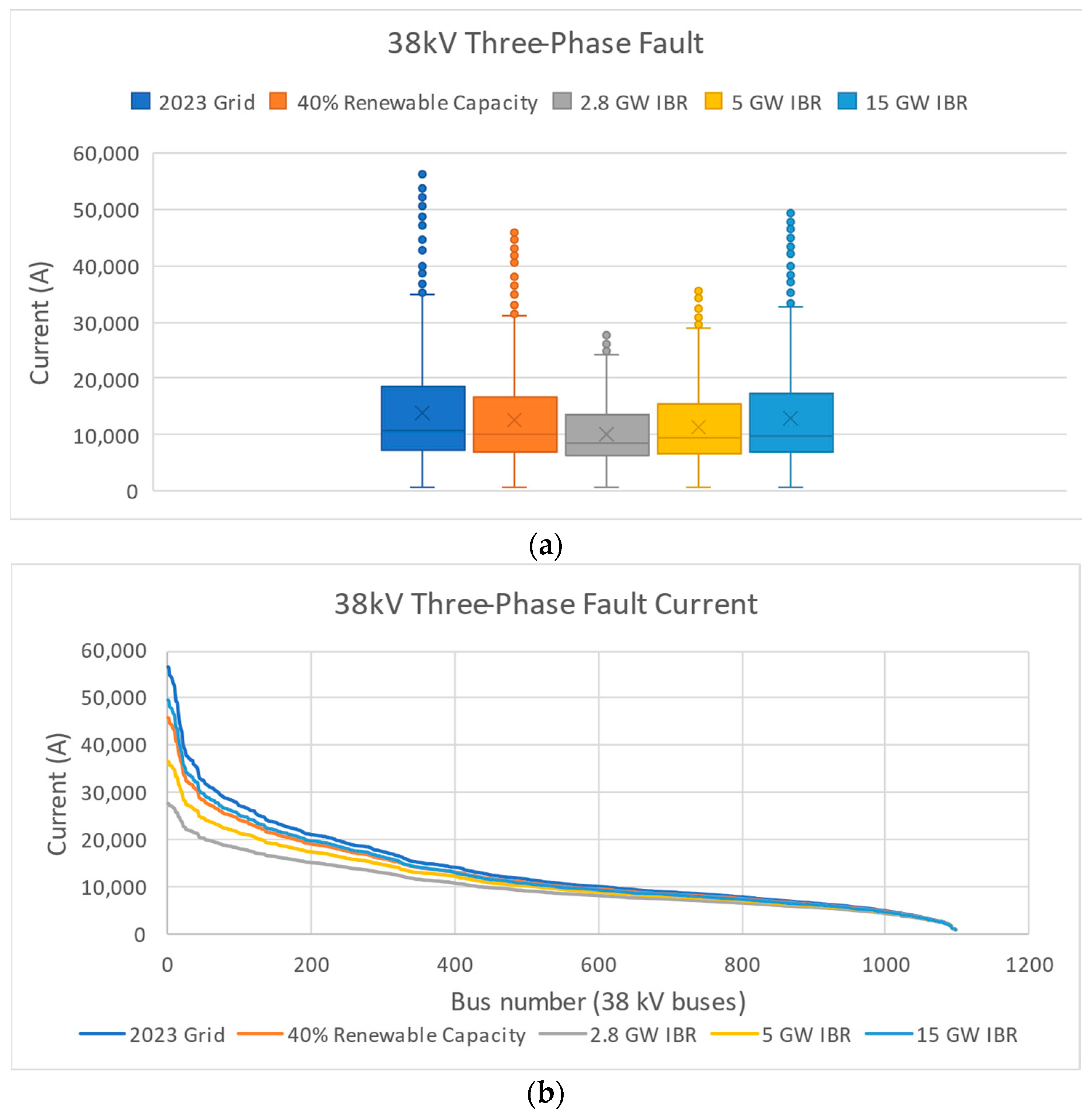
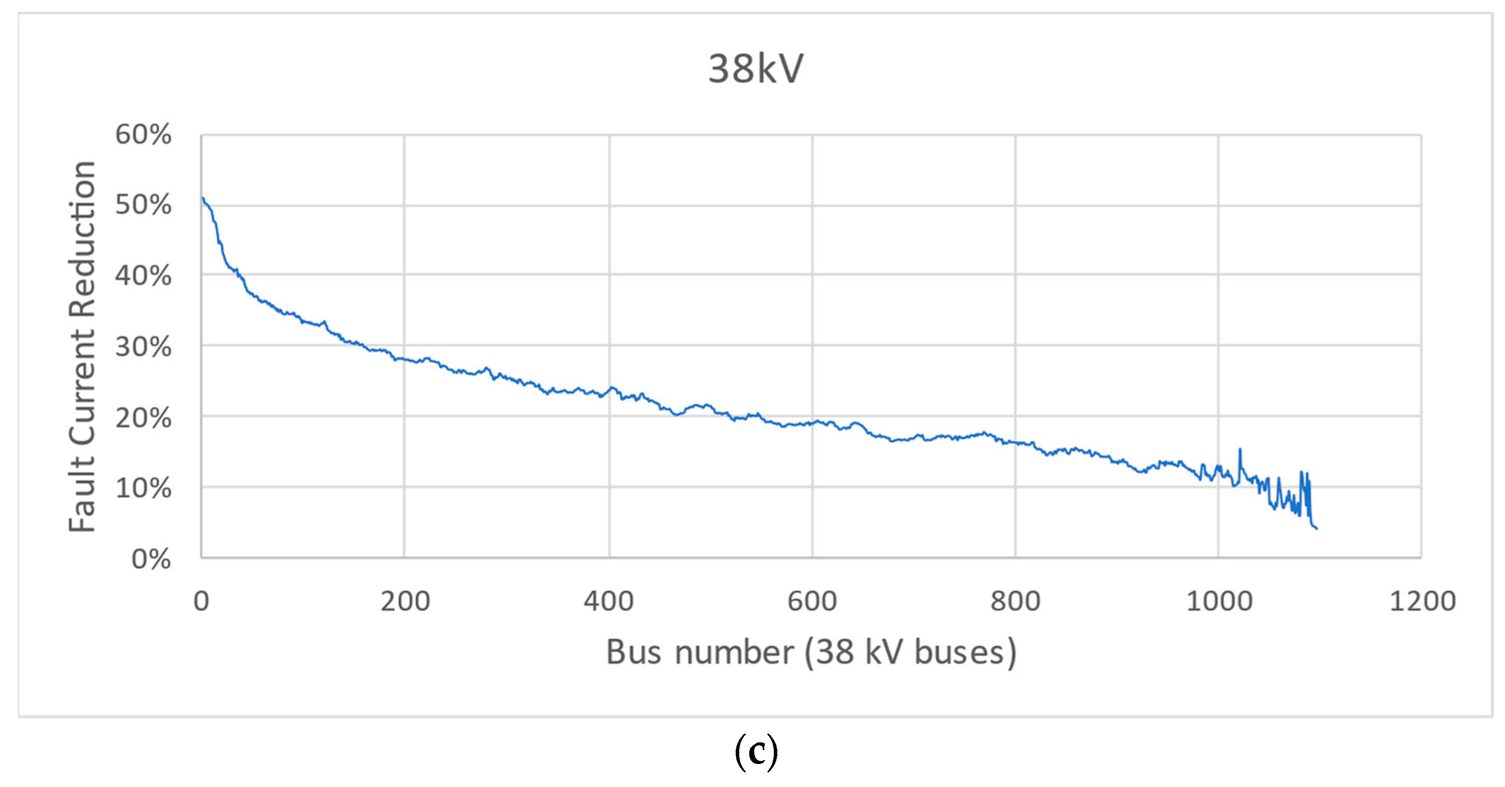
Figure 3c and
Figure 4a,b present an analogous analysis of the 38 kV subtransmission system, facilitating the derivation of parallel conclusions. Specifically, buses exhibiting a greater inherent strength undergo reductions in short-circuit levels of approximately 50%, while those situated in weaker segments of the grid observe more modest reductions, around 10%.
4.4. Single-Line-to-Ground Fault Current Analysis
In the context of a single-phase analysis, the authors presuppose that all IBRs adhere to the specifications outlined in [
15], incorporating negative-sequence injections equivalent to 50% of their positive-sequence counterparts. This assumption holds significance given that negative-sequence source impedances influence ground current injections, directly impacting the sensing of protective relaying systems. Single-line-to-ground (SLG) faults, being the predominant fault type, typically exhibit lower current contributions than three-phase faults (excluding those in close proximity to synchronous generation plants).
Figure 5a,b display a parallel analysis of the results presented in the preceding subsection, focusing on the 115 kV and 230 kV transmission system. Similar conclusions can be inferred, along with the associated risks to protective relaying. Concluding the analysis,
Figure 5c,d delve into the case of the 38 kV subtransmission system, as initially emphasized by the authors in [
9], highlighting potentially diminished impact due to the inherently weaker nature of the subtransmission system.
4.5. Potential Improvement of Synchronous Condensers and STATCOMs
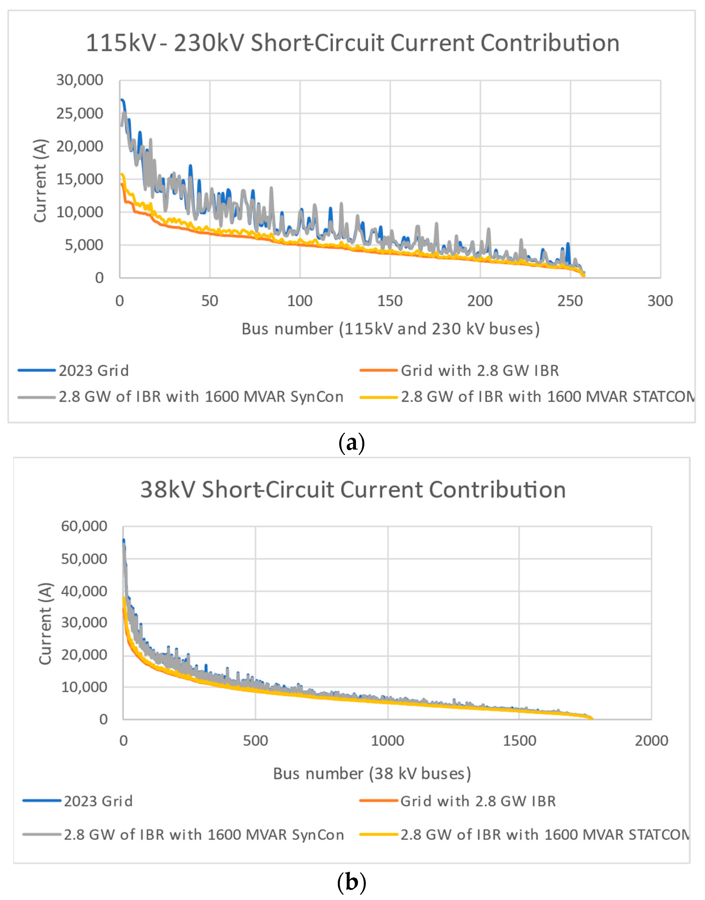
Further analysis in this paper includes replacing the existing synchronous generation fleet with synchronous condensers (SynCons). These were added to the case of the minimum IBR-only scenario (2.8 GW of IBR nameplate). The sizing method for SynCons was derived from trial and error until the same short-circuit levels experienced in the base case were achieved. The amount of SynCons that resulted from this analysis was about 1600 MVAR. For further comparison, the authors also added 1600 MVAR of STATCOMs in the same locations as where the SynCons were studied (existing synchronous generation plants) to quantify their impact. The results are shown in
Figure 6a (115 kV and 230 kV networks) and
Figure 6b (38 kV network). In this paper, only the LLL case was observed to limit the number of results and keep the text concise. As expected, the addition of SynCons counterbalanced the weakening of the grid very well due to synchronous generation plant retirement. However, the STATCOMs cannot provide significant improvements, as they too are IBR-based, and their short-circuit current contributions are limited.
4.6. Model Limitations
Enhancing modeling accuracy is imperative for ongoing research, and this aspect will be integrated into forthcoming efforts. Subsequent investigations should encompass comprehensive power flow scenarios for upcoming phases of IBR installations. These scenarios involve a transition to elevated levels of both renewable energy generation and battery storage, replacing decommissioned units while expanding the overall generation fleet. Moreover, the Puerto Rico grid features hydroelectric units that were omitted from this study due to their unreliable availability. Currently, these units primarily function as synchronous condensers, offering reactive power support. Future considerations may explore leveraging the hydroelectric generators to bolster grid resilience by augmenting short-circuit current levels.
5. Conclusions
As the Puerto Rico generation mix undergoes a transition towards achieving 100% renewable energy, the imminent shift to instantaneous 100% IBR generation is anticipated to transpire within the next 2–3 years. This evolution introduces a noteworthy impact stemming from the minimal instantaneous IBR generation in the mix, marked by the deactivation of all synchronous machines. The consequences manifest as substantial reductions in system strength, with a notable implication being the compromised reliability of several relays in detecting faults within transmission and subtransmission lines.
The addition of 1600 MVAR of synchronous condensers installed in the same location of existing synchronous generation plants is sufficient to offset the short-circuit reduction caused by the retirement of the entire synchronous generation fleet; however, these units have a very large cost. These system investments will likely be required to ensure protection dependability and selectivity. The authors also studied the impact of STATCOMs as an alternative to synchronous condensers; however, STATCOMs are also based on bi-directional inverters and have similar limitations to IBRs themselves. As a result, STATCOMs, while being able to provide many other grid services, cannot re-sensitize transmission fault current levels.
Fortunately, the most significant reductions in both three-phase and single-line-to-ground fault currents are expected in regions characterized by high fault currents. Although these reductions can exceed 80%, the minimum fault levels are still higher than what is required to be detected by microprocessor-based relays. Conversely, areas where the issue is more pronounced are those that already exhibit low fault currents, but the minimum levels are also sufficient to allow relays to sense faults. This outcome offers valuable insights, warranting further in-depth exploration and rigorous analysis to empower the transmission operator in comprehending the full extent of the problem and devising effective solutions. This encompasses initiatives such as fuse replacements to address the challenges associated with this evolving scenario. However, the impacts of short-circuit ratios and effective short-circuit ratios (SCRs and ESCRs) are very significant. SCR ratios can drop, accordingly, by up to 80% in some regions of the grid. This can create instability for grid-following IBRs (essentially all utility-scale PV and wind power plants). This dynamic behavior and corresponding study were not addressed in this paper and will be a subject of the authors’ future work.


