1. Introduction
The global positioning service (GPS) has become a very important technology, especially in the military and commercial fields. Global positioning systems can be used to monitor and manage traffic congestion, parking, street lighting and urban noise in real time. However, satellite signals fade near buildings or due to other factors [
1,
2,
3,
4]. Heterogeneous networks can be used for environmental monitoring, military surveillance and target tracking [
5]. The 5G system provides device to device (D2D) communication capabilities to obtain real-time location information to cope with the increase in road traffic [
6,
7,
8]. Indoor or outdoor positioning services, such as the location-based service (LBS), are widely used for software computation [
9]. GPS can be widely used, especially outdoors [
10]. Contrastingly, indoors, radio waves from satellites are blocked, and indoor environments are susceptible to interference from multipath effects and fading caused by moving objects. Therefore, indoor positioning system technology is becoming more important [
11,
12,
13,
14].
Indoor positioning technologies include Bluetooth, RFID, Wi-Fi, ZigBee and UWB. UWB technology can achieve better accuracy, at centimeter level, the iBeacon protocol can incur an error of 1 to 2 m, whereas Wi-Fi accuracy ranges from 2 to 3 m [
15]. The fine timing measurement (FTM) method can provide better location information for mobile device positioning [
16]. The round-trip time (RTT) allows the receiver to measure the time it takes the signal to travel to and from nearby wireless access points. The measurement signal timestamp is recorded in nanoseconds, with an error within 1 to 2 m [
16]. The RSSI signals from different wireless access points and different transmission distances cause signal fading. When the received signal is fading, the distance between the receiving point and individual wireless access points is estimated, and the coordinates of the receiving point are calculated by using a triangulation algorithm. The signal is subject to different shadow fading effects [
17], and the radio channel method can locate the long-term evolution (LTE) system [
18].
The positioning algorithms can be divided into ranging methods, such as the angle of arrival (AOA), time of arrival (TOA), time difference of arrival (TDOA), round trip time (RTT) and RSSI, and the currently implemented method for positioning in Wi-Fi wireless networks is non-ranging positioning signal fingerprints. The AOA method calculates the position of the receiving point by using an antenna array to receive the angles of the directional antennas from two or more transmitting points. The disadvantage is that there are large errors in non-viewing angle environments, requiring the configuration of the antenna array. The TOA method calculates the distance between each transmitter and the receiver by using the time required by each transmitter signal to reach the receiver. Its disadvantage is that time synchronization must be maintained between the receiver and the transmitter. Otherwise, the signal transmission speed can reach the speed of light, even if it is 1 us. A difference of seconds will cause an distance error of 300 m, necessitating extremely high requirements for time synchronization. The TDOA method measures the time difference between receiving points and different transmitting points. If there are three transmitting points, two sets of TDOA hyperbolas can be obtained to calculate the position of the receiving point. The disadvantage is that the transmitting points must maintain time synchronization with each other.
The RSSI method involves the receiving point receiving wireless signals from different wireless access points. Different levels of signal fading occur due to different transmission distances. Therefore, the distance between the receiving point and individual wireless access points can be estimated by the degree of received signal fading, followed by the use of the triangulation algorithm to calculate the coordinates of the receiving point. The disadvantage is that it is easily affected by factors such as people walking in the environment and indoor blockings, resulting in additional fading of the signal. The signal fingerprint method is divided into two stages: the offline stage and online stage. First, using a mobile device to select measurement points within the experimental range allows for the measurement of a large amount of RSSI information from surrounding APs for later use in the offline stage to establish a radio map. In the online stage, the mobile device measures the RSSI value at an unknown location and compares it with the radio map of the previous stage to estimate the current location. The disadvantage is that any changes in the environment may change the signal fingerprint corresponding to each measurement point.
Due to the high complexity of the indoor environment, wireless signals have multi-path propagation and multi-path reflections that make the strength and quality of wireless signals difficult to predict [
19]. The factors causing signal loss in the channel propagation of wireless signals are the propagation path loss model, the large scale propagation model and the small scale propagation model [
20]. After the wireless signal is sent out from the transmitter, it spreads in all directions in space. In different environments, the power of the received signal is inversely proportional to the square of the distance [
21,
22,
23]. In the free space propagation model, there is no additional loss between the transmitter and the receiver.
The strength of the received signal is a random variable affected by the shadowing effect caused by various obstacles in the signal propagation. The shadowing effect causes the received signal power to follow a log-normal distribution. The factors affecting small-scale fading are both multipath fading and the Doppler effect. Multipath fading occurs when the signal from the transmitter propagates to the receiver. When the path is non-line-of-sight, the wireless signal is affected by different obstacles, causing the signal to produce reflection, refraction, scattering, diffraction, etc. It causes the receiving point to receive the signal of each path. Since the signal of each path is affected by different obstacles, it presents different fading and delays.
However, this paper used RSSI with a different calculation method compared to cumulative distribution function (CDF), hybrid, Kalman filtering (KF) and threshold filtering (threshold) with testing samples and APLE. This paper used the CDF method to filter the RSSI data of each AP, trying to find the RSSI of each AP in the entire sample, based on CDF statistics ranging from 15% to 85%. RSSI is used as the threshold for signal screening to remove the strongest and weakest parts of the signal and replace them with the previous RSSI. This paper was also processed by the KF to reduce the estimated distance errors caused by surge signals. A threshold based on the average and standard deviation of the RSSI was used. This threshold directly removed the RSSI values that did not meet the conditional expression from the samples. Based on the threshold and KF, the original RSSI of each TP was filtered through the threshold filter. This filtered out the surge signal and the RSSI was replaced with the RSSI from the previously filtered signal. Then, the KF was used to smooth the filtered RSSI.
2. System Model
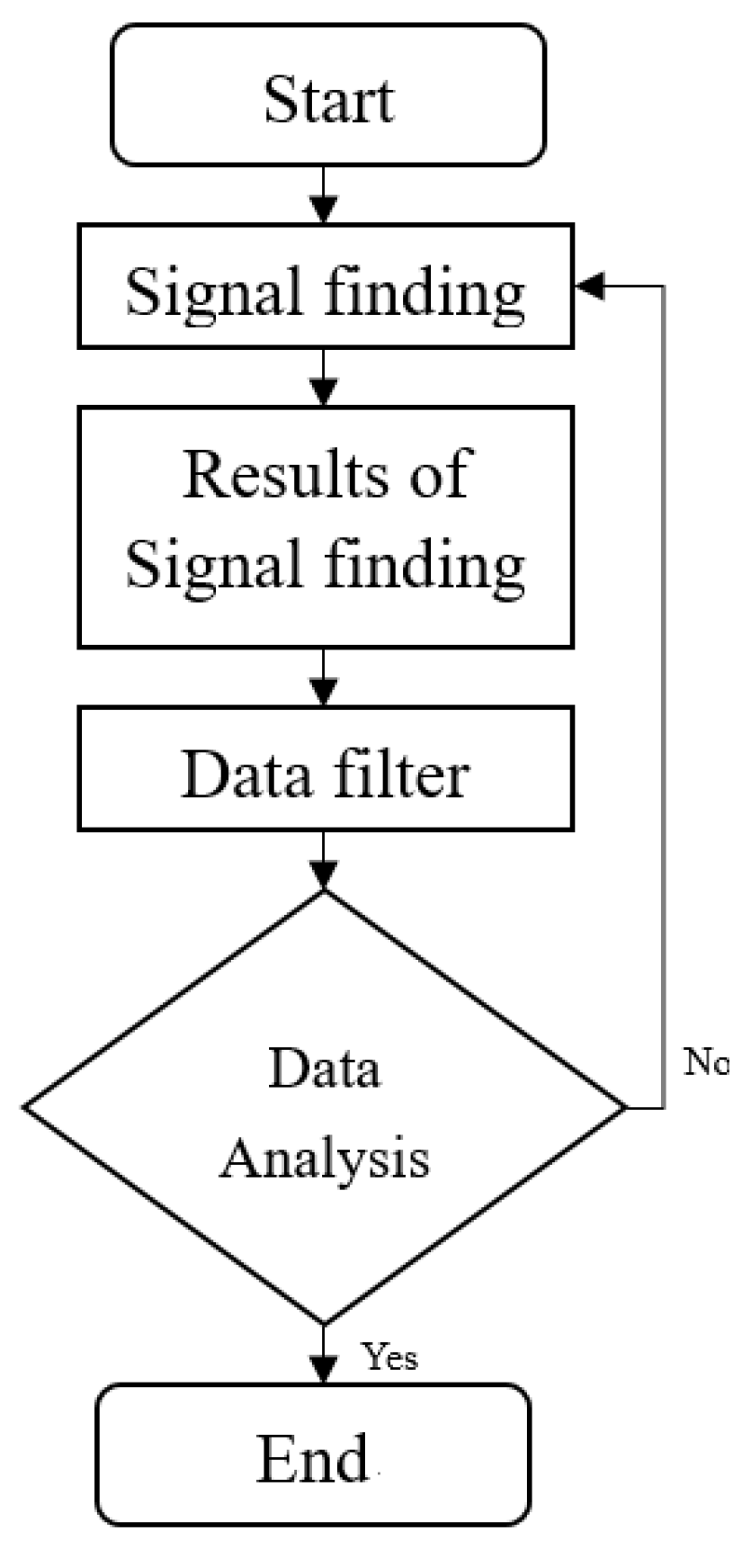
Figure 1 shows the flow chart of signal measurement, where the mobile device measures APs, with three values being obtained at each measurement point: delay time, total number of measurements and file name. The delay time is set in per second to collect the BSSID and RSSI of all APs in the environment and then filter out the RSSI of the three APs. The Wi-Fi frequency band is divided into two frequency bands: 2.4 GHz and 5 GHz, tested at
n testing points through mobile devices. Each method reads the data of the testing samples individually and extracts the data, such as RSSI, BSSID and the reference AP coordinates.
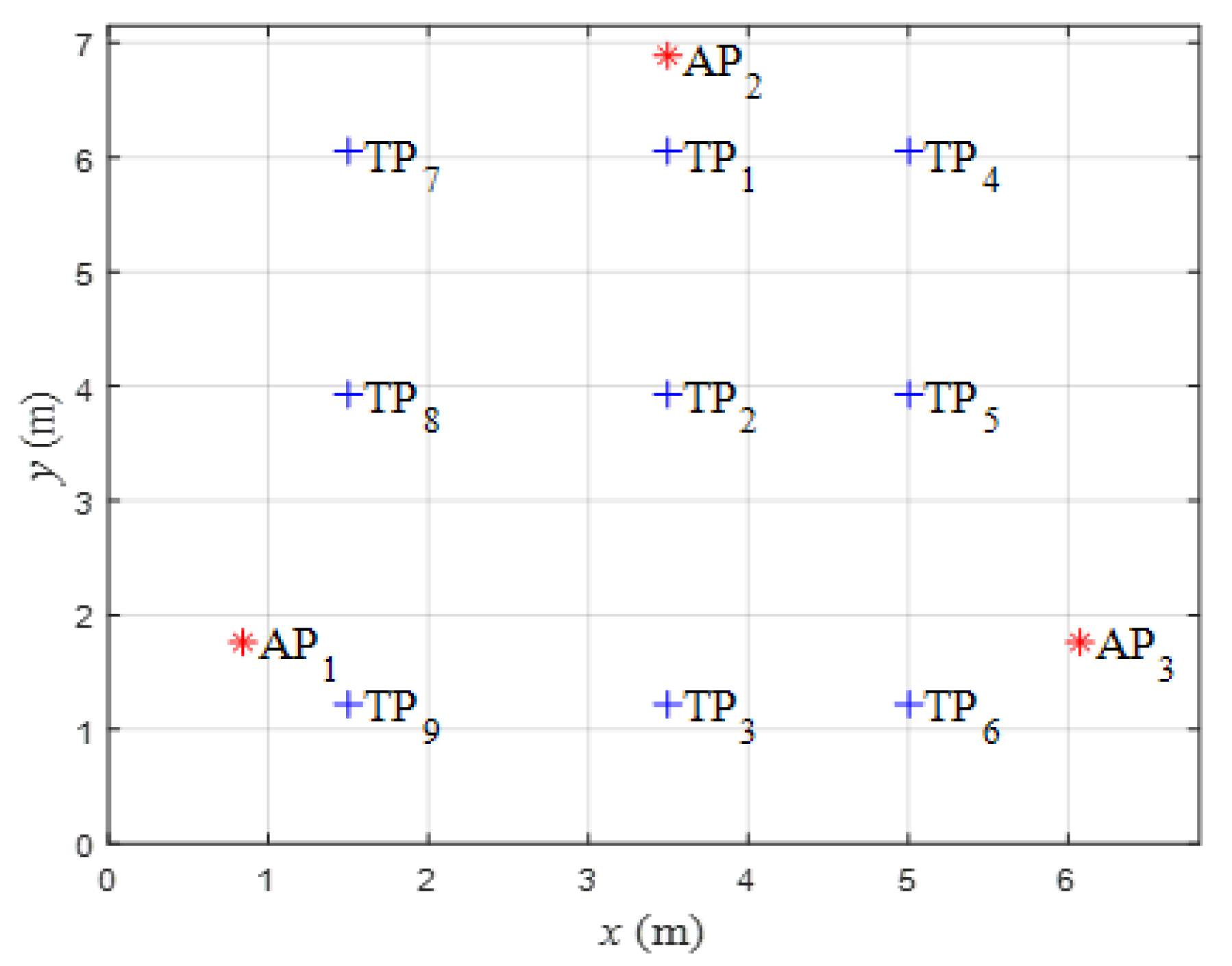
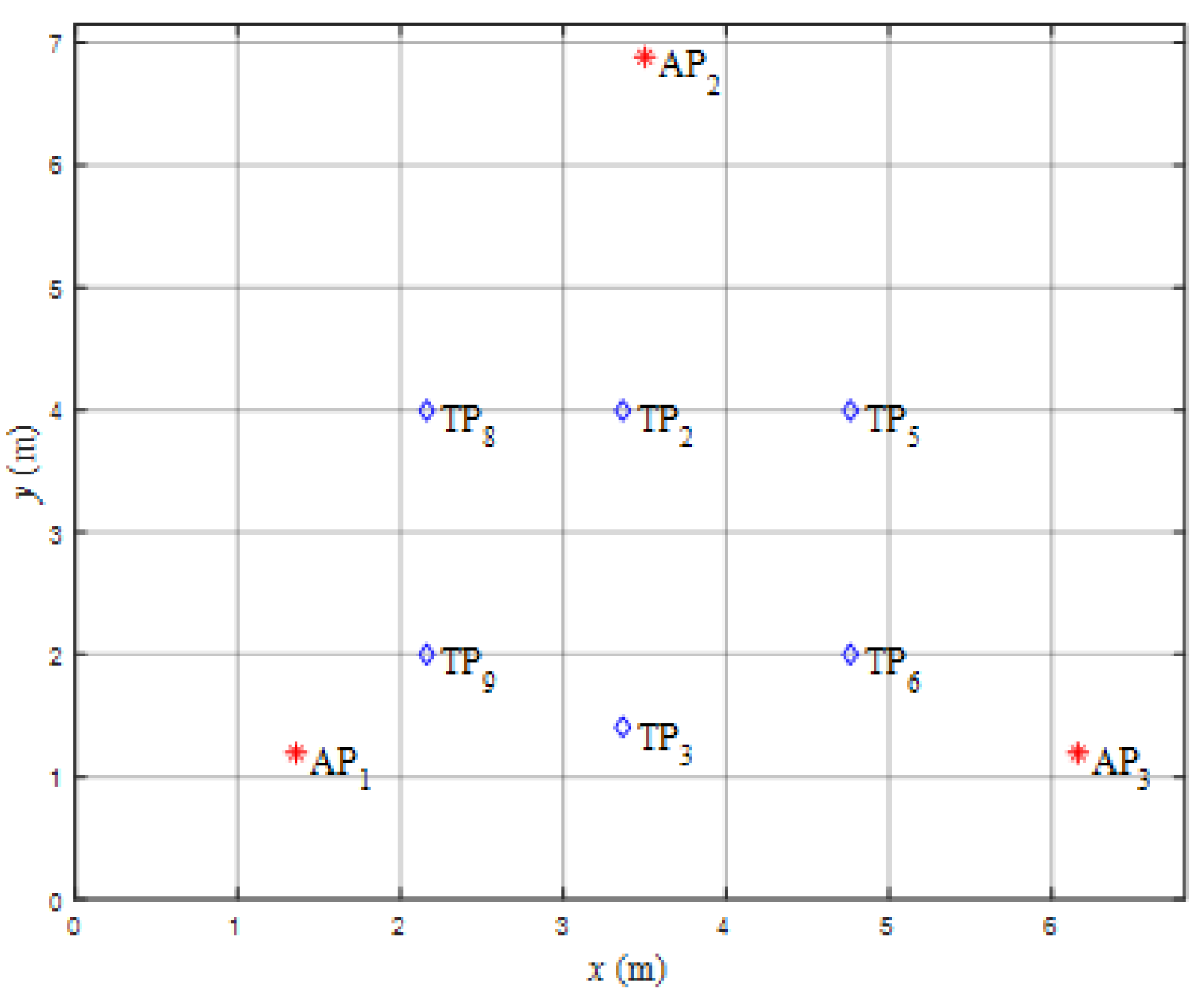
Figure 2 shows that there are
n testing nodes, TP
1, TP
2 … TP
n, and three reference points of wireless access points AP
1, AP
2 and AP
3.
Table 1 shows that there are 300 samplings, and PLE (
n) is from 1.2 to 3. The locations for AP
1, AP
2 and AP
3 are as follows: AP
1 (0.84 m, 1.76 m), AP
2 (3.50 m, 6.88 m) and AP
3 (6.08 m, 1.76 m). The testing points for each are shown in
Table 1.
In
Table 2, the reference signal strength of RSSI is represented by
P(
d0) where the reference distance,
d0 is 1 m. This is used to estimate the TP
n of each node RMSE, with
n ring from 1 to 9.
P(
d0) functions on both 2.4 GHz and 5 GHz frequencies, corresponding to 3 APs. We set
d0 = 1 m away from the APs to measure the
P(
d0) corresponding to each TP.
With a random variable, the propagation path loss model can be expressed as
where
Xσ represents shadowing fading with a log-normal distribution with a zero mean, and its standard deviation,
σ, ranges from 4 to 10 dB.
The estimated distance between the
mth testing point of TP
m and the
jth AP is denoted as AP
j.
is the received power at the
mth testing point of TP
m, and can be expressed [
24,
25,
26] as
where
is the estimated distance between the
mth testing point of TP
m and the
jth AP, AP
j.
P(
d0) is the received power at the distance
d0 from AP
j.
is the received power at the
mth testing point of TP
m from
jth wireless access point AP
j. The symbol
n represents the path loss exponent of the wireless channel.
The Kalman filter (KF) is a recursive algorithm widely used in path navigation and indoor positioning [
27]. In the prediction stage, the estimated value and the covariance matrix of the previous stage are used to predict the estimated value of the current stage, expressed as
and
where
is the estimated value, at time
k,
is the estimated value of the previous stage,
Pk is the covariance matrix,
F is the transformation matrix, and
Q is the estimation error matrix.
In the update stage, the measured value of the current stage is used to update the estimated value of the prediction stage to obtain an estimated value expressed as
and
respectively, where
zk is the measured value at time
k,
R is the measurement error matrix,
Hk is the measured parameter matrix, and I is the identity matrix.
In the prediction stage, Equation (3) shows that is set to APj, the starting value of the signal, and F is the unit matrix. Pk−1 in Equation (4), is the covariance of the APj signal, serving as the estimated covariance matrix of the next sample.
The PLE is used to measure the distance between TP
m and AP
j, with as
n ranging from 1.2 to 3. This is done to determine the RMSE of each PLE and select the smallest error value as the adaptive PLE (APLE) of TP
m. The RMSE distance is expressed as
where
N is the total number of the measurements. The symbol
is the actual distance between the
mth testing point, TP
m and the
jth wireless access point, AP
j. The APLE can be obtained from the minimum distance error,
, for the channel between the
mth testing point TP
m and the
jth wireless access point AP
j by the following equation:
where
is the APLE for the channel between the
mth testing point of TP
m and the
jth wireless access point, AP
j.
The triangulation positioning algorithm establishes a wireless channel model in the environment to substitute the received signal strength in determining the distance between the testing device and each AP. This substitution is aimed at reducing the number of positioning points to no more than two, through the signals provided by three APs. The minimum positioning error was achieved by calculating the distance using the three APs that intersect at a single point.
The RSSI is used to estimate the distance between the position and the wireless access point. The triangulation algorithm is used to minimize the positioning error [
12]. The estimated distance of the testing position (
x0,
y0) is expressed as
where (
x0,
y0) is the estimated coordinate of the testing node, (
xk,
yk) are the coordinates of the
k reference APs and
is the estimated distance between the testing node and the
kth AP node. When the reference node is 3, the equations can be derived based on Equation (10) as follows:
and
To express the coordinates of the testing node, the least squares estimates are obtained as follows:
where
and
According to Equation (13), the estimated coordinates and actual coordinates of the
mth testing point are calculated, and the positioning error is calculated according to the RMSE method expressed as
where
and
are the actual coordinates of the
mth testing point, TP
m, and
and
are the estimated coordinates.
The positioning error calculated by Equation (16) was compared. The sample positions of the signals generated by each AP were different. Therefore, the sample position of the signal is determined by using both the previous samples and a fixed PLE changed into APLE. The final RSSI was converted into an estimated distance, and the estimated coordinates were calculated by Equation (13), with reference to the coordinates of the AP.
3. Surge Processing
During the time a signal is received or transmitted, it changes rapidly due to environmental obstruction, the movement of people and other factors. These signals cause a significant increase in the estimated distance value, resulting in a significant increase in positioning errors.
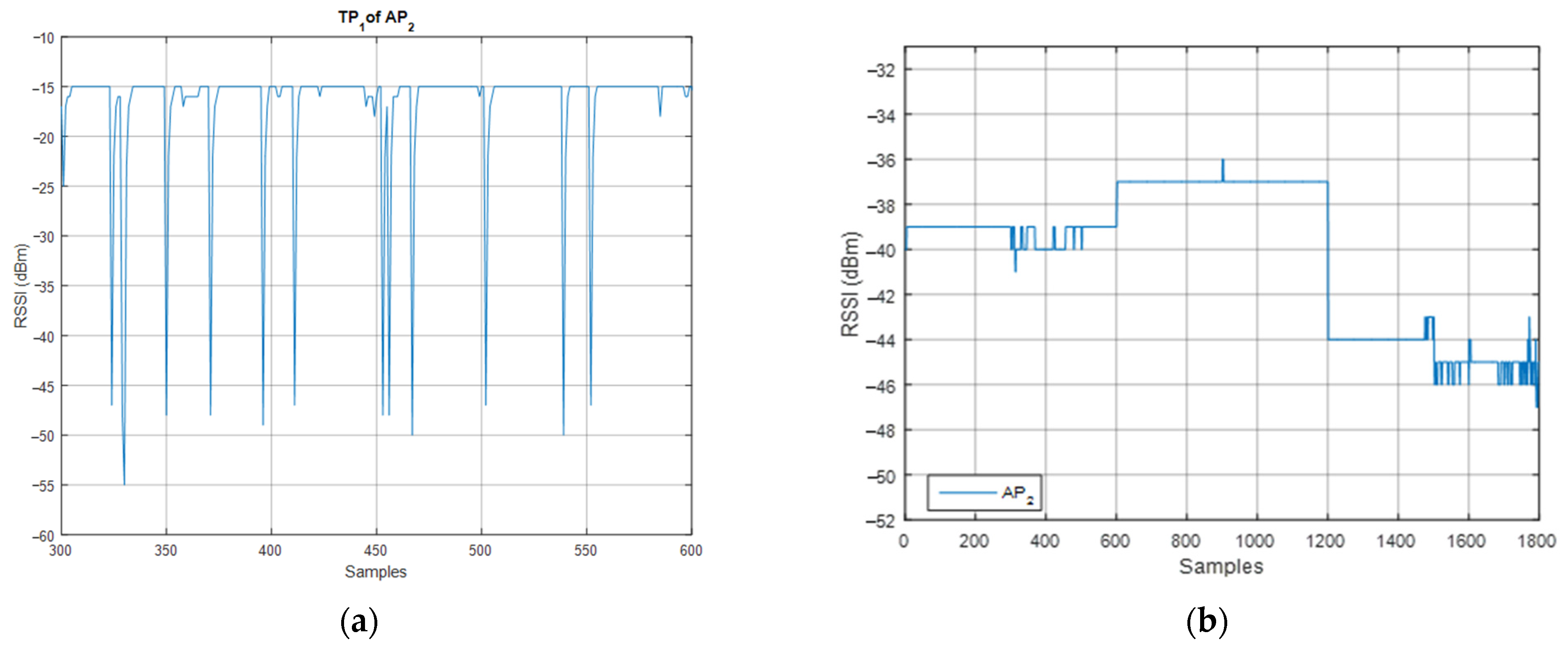
Figure 3a,b show the basic signal of 2.4 GHz and 5 GHz in RSSI.
Figure 3a shows the RSSI data for AP
2 at TP
1, at 2.4 GHz, representing a total of 6 days of signal collection.
Figure 3b depicts the signal at 5 GHz. Although the signal received by AP
2 at the testing point is stable compared to the 2.4 GHz signal, there are some small amplitude differences. The signal can be removed through signal fading.
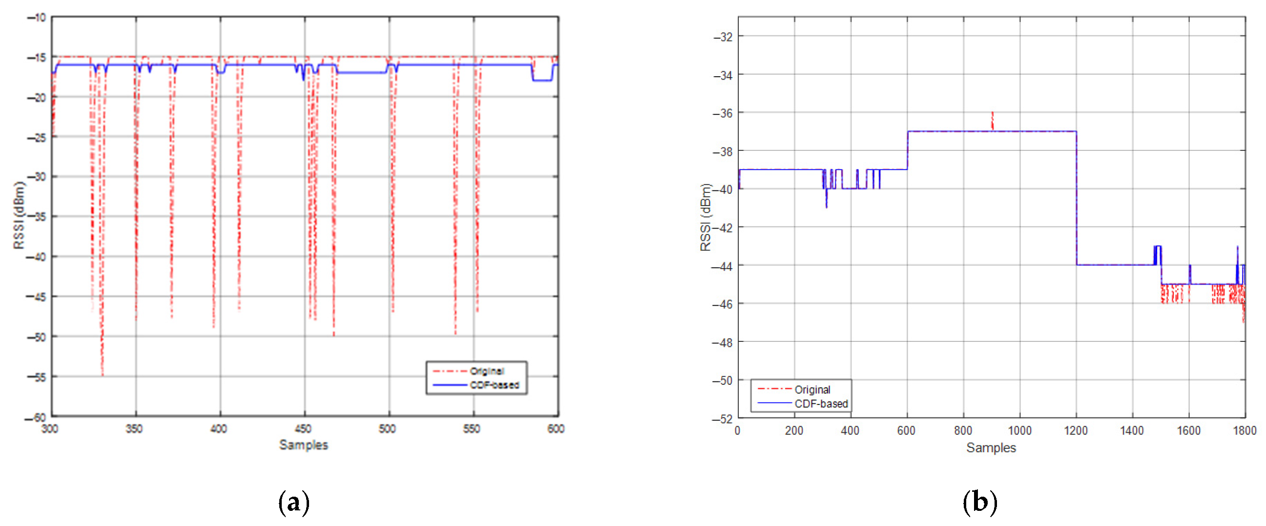
This paper used the CDF method to filter the RSSI data for each AP. The RSSI values closer to the 15% and 85% range were determined based on the CDF statistics of each AP in the entire sample. The strongest and weakest parts of the signal were removed and replaced with the previous RSSI. The results are shown in
Figure 4a,b, which illustrates the comparison between the 2.4 GHz and 5 GHz data for AP
2 at TP
1, using CDF signal filtering and the original signal, respectively.
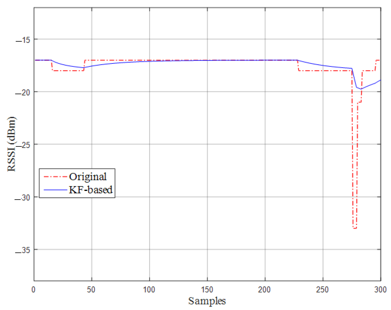
This paper also used the KF to reduce the estimated distance errors. The RSSI for AP
j at each TP in the sample obtained a smoother signal and removed the influence of the signal by using the KF.
Figure 5 shows the comparison of the RSSI data for AP
2 at TP
1 using signal samples after applying the KF and the original data. This greatly reduced both the part of the surge signal and the distance estimation error of APLE.
By using positioning samples, a threshold was used on the average and standard deviation of the sample. The threshold range was determined based on the average and standard deviation. It directly removed the RSSI values that did not meet the conditional expression. Based on the RSSI of the sample, the parameter “
α” adjusts the sampling range as expressed below:
where α > 0,
Pj(
n) is the RSSI data,
Pj,avg is the average data, and σ
j is a derivation datum.
The PLE of the three APs is set to 2 to calculate the estimated distance values based on the RSSI after signal processing. The actual distance between the TP and AP was calculated using Equation (17) as a measurement of performance comparison.
In
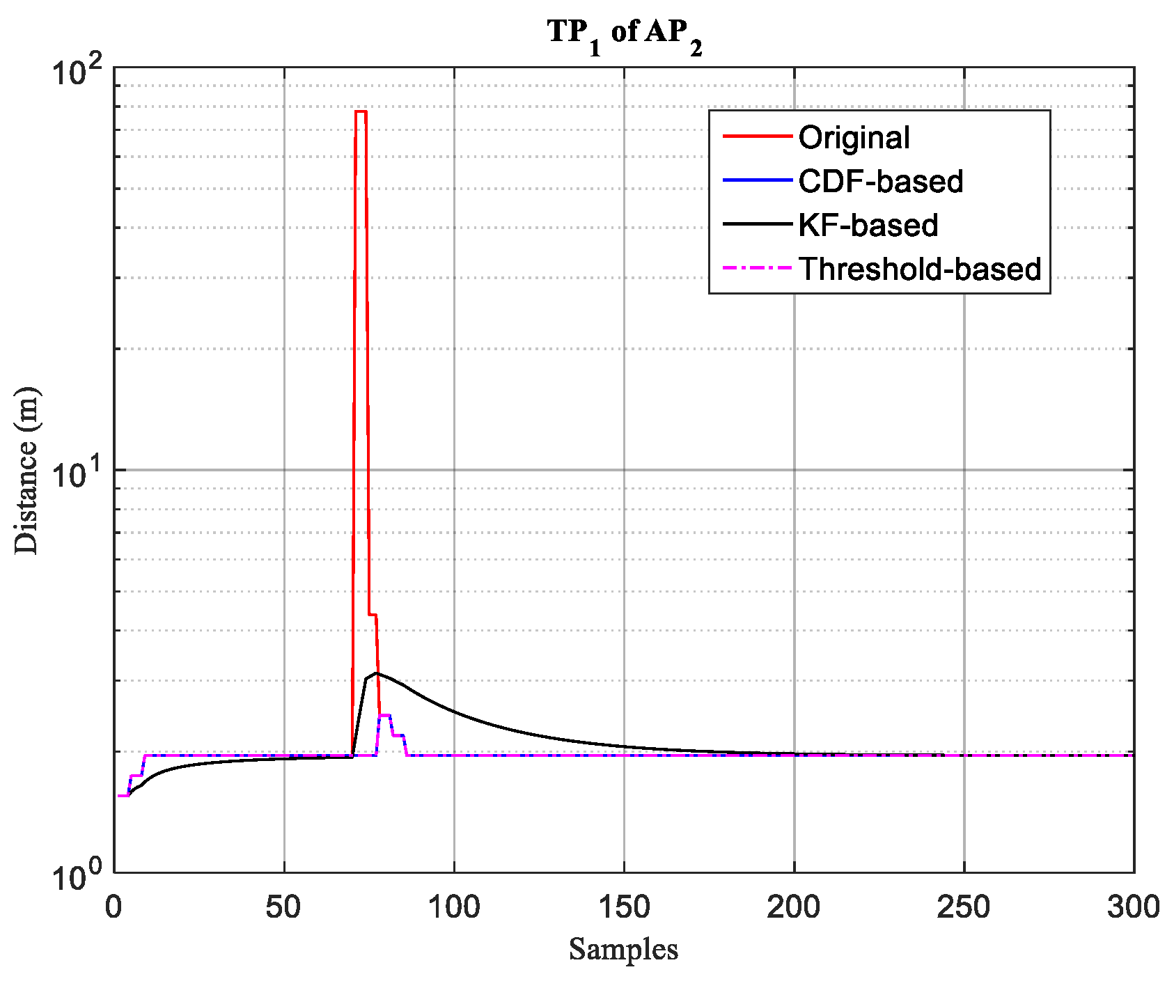
Figure 6, the distance estimation between AP
2 and TP
1 was compared with the original signal through various processing steps. The abnormal RSSIs between 50 and 100 samples were removed to reduce the distance error. The RSSIs have been filtered by CDF signals and the threshold methods, resulting in a distance error of 1.13 m, while the distance error through KF is 1.27 m, and the distance error of the original signal is 4.02 m.
The signal processing is further modified based on a threshold and a KF to filter the signal. This involves passing the signal through the threshold and replacing the original RSSI of AP
j for each TP with the RSSI of the previous filtered signal. To smooth the filtered RSSI by the KF and to calculate individual estimated distance error values through different PLEs, Equation (16) was used. Using Equation (17), the minimum error value as the TP
m APLE of AP
j can be found.
Figure 7 used the hybrid method to process the RSSI data from TP
7 and AP
3 in 2.4 GHz and compared the APLE using the threshold method.
4. Experimental Results
This paper used two different signal bands, 2.4 GHz and 5 GHz. A mobile device sent out Wi-Fi scans at 9 testing points, every second. The mobile device then received the results and sent data to the cloud.
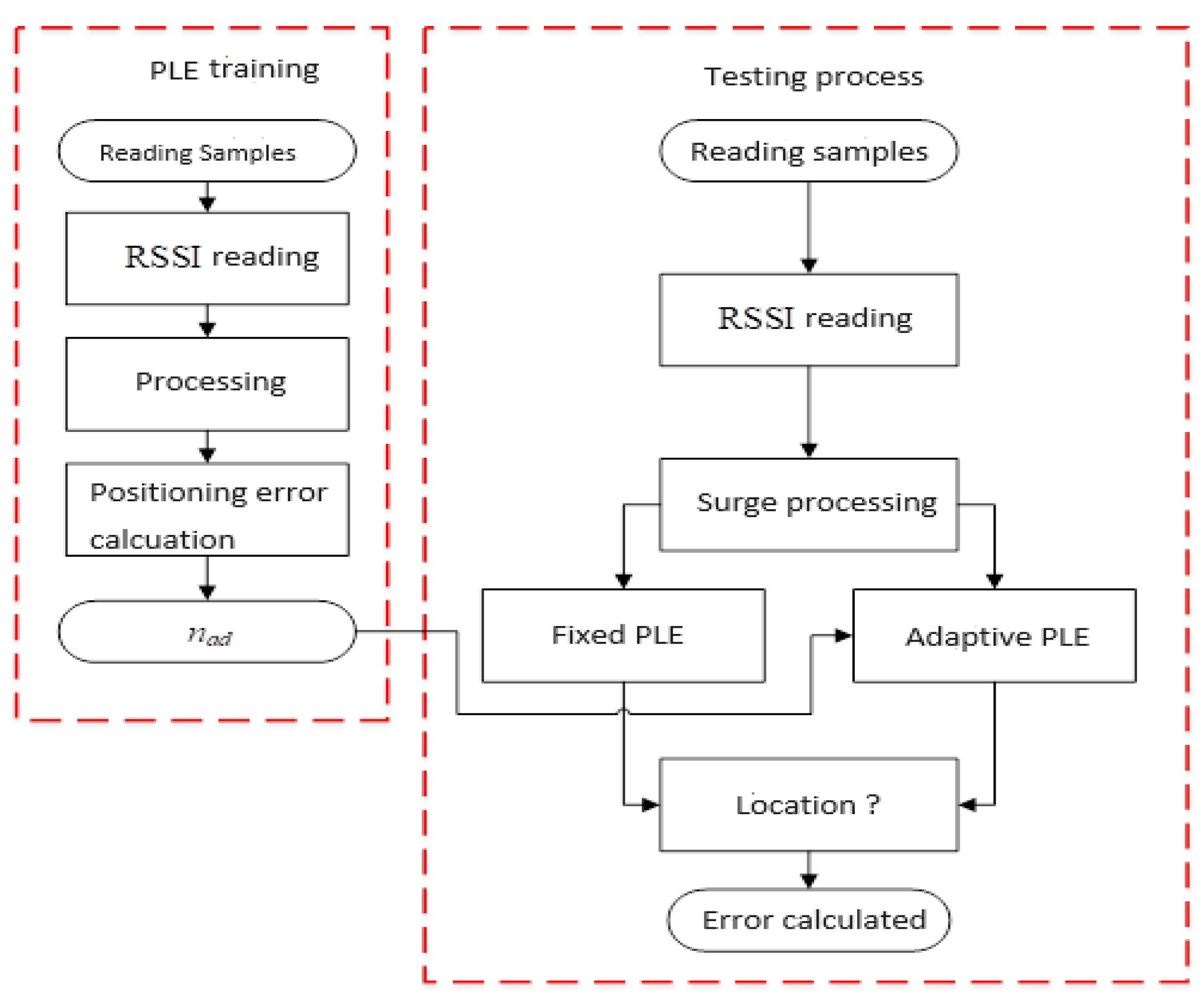
Figure 8 shows the positioning flow chart, which includes 4 types of surge processing. Each type reads the data of all testing samples individually and extracts data such as RSSI, BSSID and the coordinates of the reference AP. The surge processing uses the CDF, KF and threshold methods to reduce RSSI surge signals. The simple positioning skips the surge processing block and directly uses fixed PLE or APLE to calculate the estimated coordinates. CDF was performed on individual APs in the entire set of testing samples. The sample locations of surge signals were different for each AP. Once the sample location of the surge signal was found, the previous sample was used to fill it. The fixed PLE and APLE were used to convert the filtered RSSI into the estimated distance. The estimated coordinates were calculated with the coordinates of the reference AP. The APLE calculated the estimated distances of the three APs and, finally, used the aforementioned distances to calculate the estimated coordinates and combined them with the coordinates of the actual measurement points to obtain the positioning error.
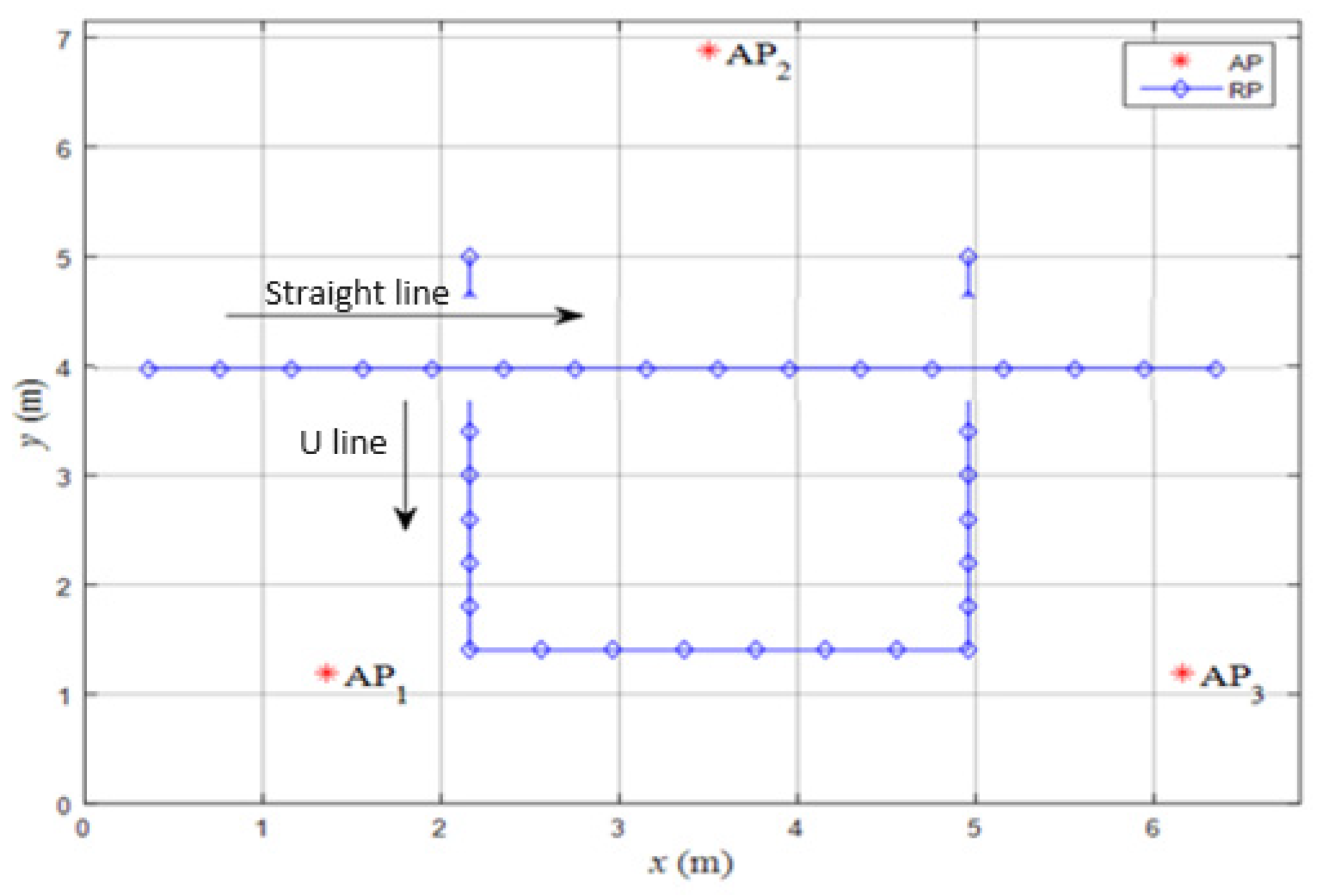
Figure 9 is a real-time positioning area where the coordinates of three APs are set. In this area, the starting point is first set to the TP coordinates, and the RSSI received by the mobile device was transmitted through the WebSocket protocol. The mobile device was used to receive the three APs, and the RSSI data of the AP were sent to Matlab R12 software for real-time positioning calculation. The real-time positioning parameters are shown in
Table 3 for calculating the estimated distance and positioning coordinates. Any position beyond the positioning area will replace the current positioning coordinates with the last positioning coordinates.
Table 4 and
Table 5 show comparisons of positioning errors
em (m) for different methods, at 2.4 GHz and 5 GHz, respectively. The APLEs are obtained through the four surge signal reduction methods: the CDF, hybrid, KF and threshold.
Table 4 shows that the average positioning error obtained by CDF in the PLE training method is lower than that achieved by other methods.
Table 5 shows that the average positioning error obtained by using the CDF is lower compared to other methods.
The testing point transmitted 2.4 GHz RSSID and RSSI information to Matlab R12 software through the triangulation positioning algorithm to obtain the estimated point. The positioning procedure was performed every 3 s, producing 110 positioning data points every one minute and 30 s. The APLE is calculated based on the first 10 data points to enable real-time positioning for the remaining 100 data points.
After using the hybrid, KF and threshold methods for signal processing, real-time positioning was performed.
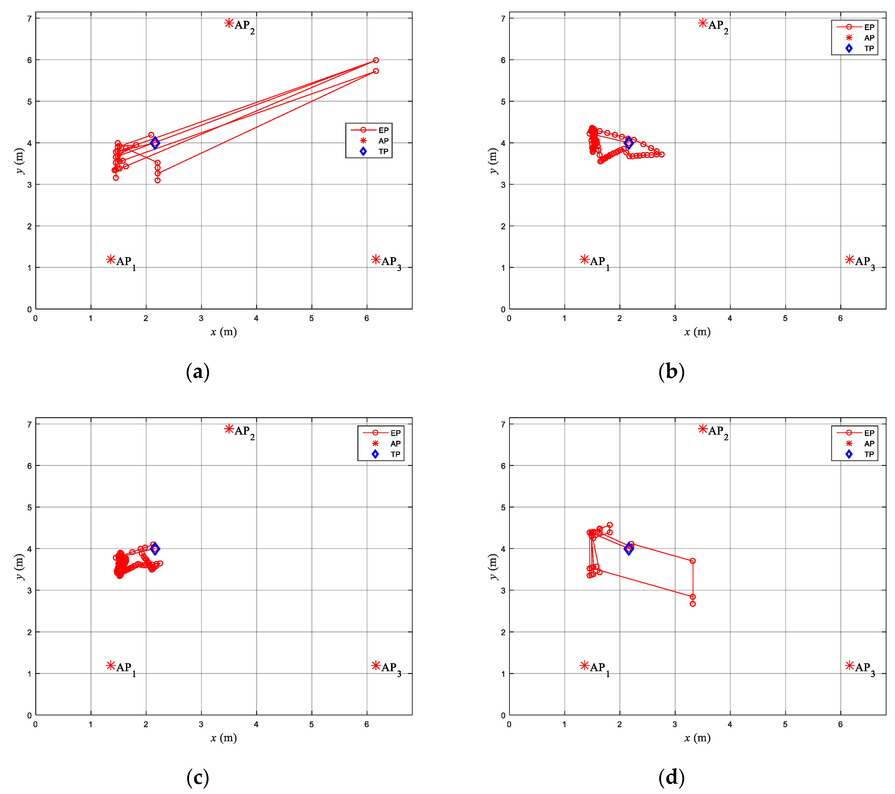
Figure 10a–d show a lower estimated error value compared to the simple method, in which the adaptive PLE was used. In
Figure 10, the positioning has been changed to TP
2. The signal is processed according to the simple, hybrid, KF and threshold methods.
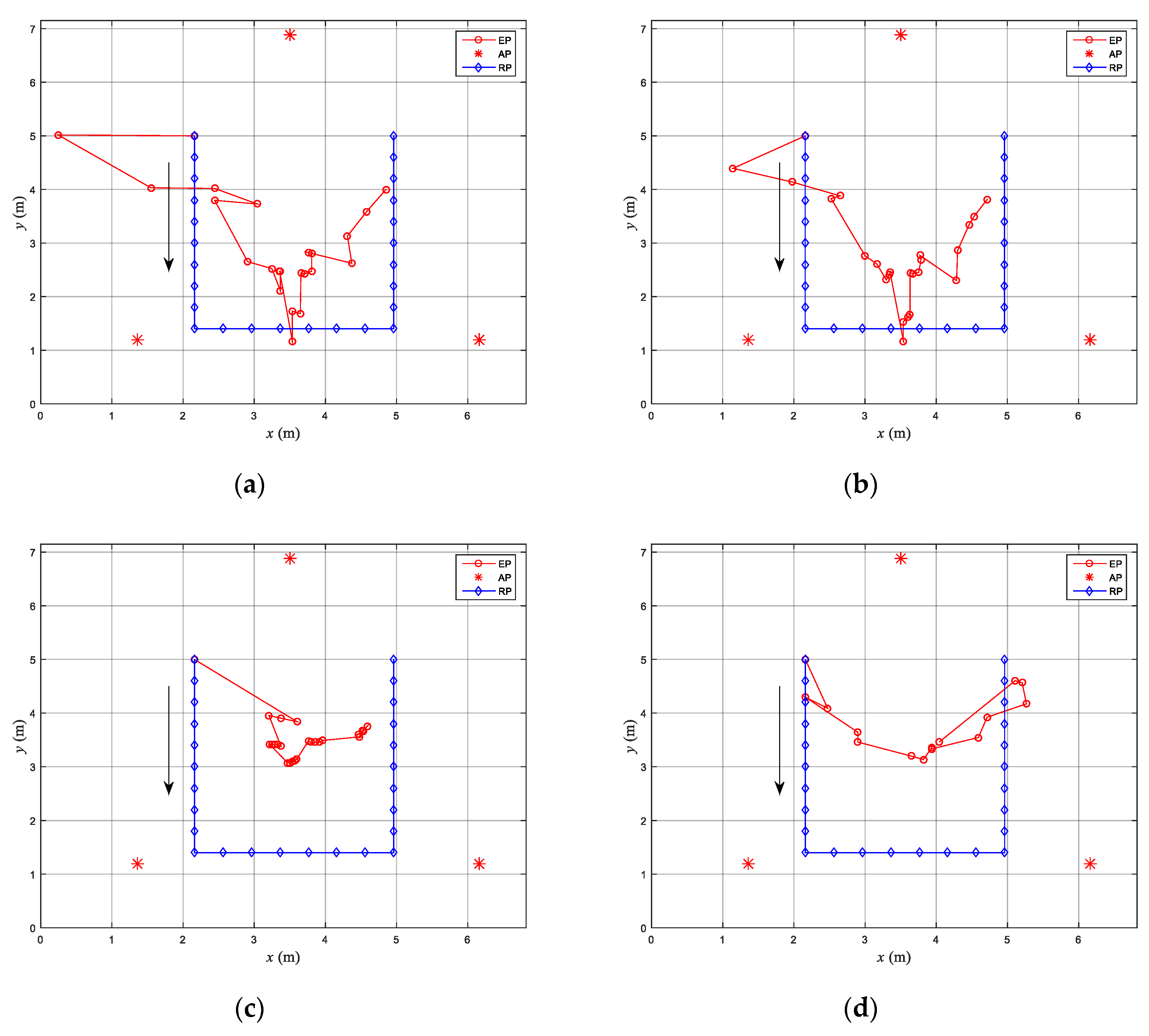
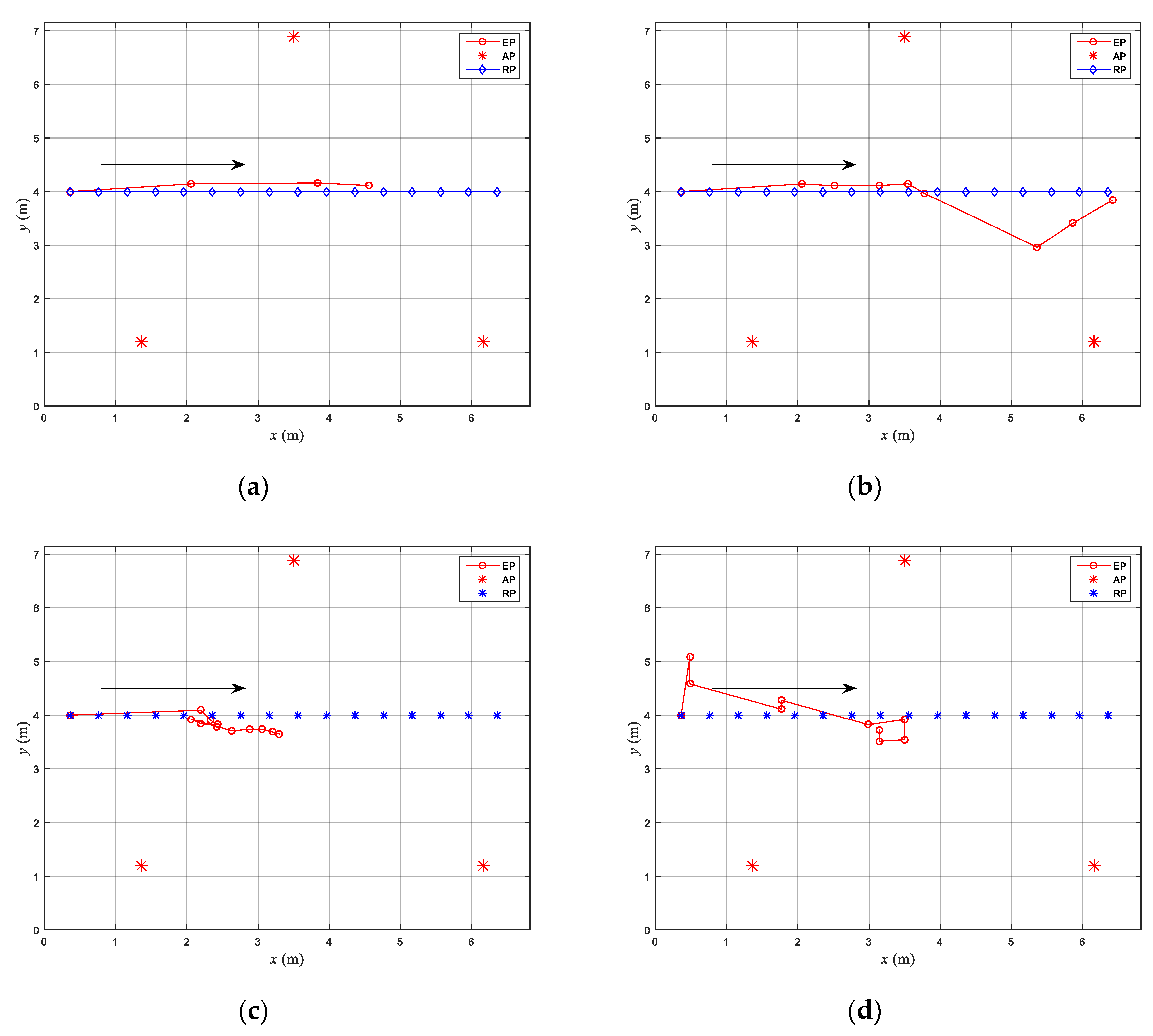
Figure 11 shows the dynamic real-time positioning path. There are two types of the actual path (RP). On is the straight line is the RP and the other is U line is the RP. The arrow direction represents the positioning walking direction. The straight line is the arrow direction from left to right. The U line is the arrow direction from up to down. The starting point is the first RP coordinate, followed by a waiting time for the mobile device to transmit the AP information for positioning calculations.
Using the RP path to perform dynamic real-time positioning and the RSSI from three APs, the triangulation positioning algorithm obtained the EP coordinates. In this process, the PLE used the APLE from
Table 4 and the
P(
d0) from
Table 2 to perform positioning operations. The hybrid and threshold methods also require setting a threshold value, which is recorded every second. The data collected within 1 min is set as the threshold value. The remaining positioning data is positioned after signal processing.
Figure 12 removed the starting point and calculated the positioning error from the estimated coordinates and RP coordinates across 25 sets of data. The positioning error of
Figure 12a is 0.96 m,
Figure 12b is 0.95 m,
Figure 12c and
Figure 12d are 1.4 m and 1.29 m, respectively. In
Figure 13, the first time was set as the starting point and was ignored. The positioning coordinates of the remaining 15 sets of data, as well as the coordinates of RP, were estimated to calculate their relationship. The positioning error in
Figure 13a is 0.93 m, in
Figure 13b it is 0.88 m, while the positioning errors in
Figure 13c and
Figure 13d are 1.46 m and 1.77 m, respectively.
Table 6 shows the comparison of experimental results for the positioning error of the proposed four methods. From
Table 6, it is observed that the best positioning testing point is TP
3. The positioning error,
em, for TP
3 is 0.73 m, 0.41 m in the CDF method, 0.89 m and 0.62 in the hybrid method, 0.72 m and 0.18 m in the KF method and 0.72 m and 0.15 m in the threshold method for
n = 2 and
n =
nad, respectively. The average positioning error is 1.985 m and 0.9975 m for
n = 2 and
n =
nad, respectively. Therefore, with the proposed APLE the position accuracy can be improved by 50% compared to the free space model for six TPs.
