1. Introduction
The design of electrical machines belongs to the most general branch of mathematical optimisation problems [
1,
2,
3], where the optimal machine’s type and final shape depends on the design criteria, viz., the objective of the optimisation. Currently, one of the most important objectives for a newly manufactured electrical machine is, even now, to maximise the power/mass ratio. Due to global warming, other aspects should be considered during the optimisation process, which would support other new ecological aspects, such as applying recyclable materials and reducing material waste during mass manufacturing. The European Commission released a plan to facilitate transitions to the circular economy model, where the goal is to improve the product’s energy and resource efficiency, empower remanufacturing, and reduce the carbon footprint of products [
4,
5,
6].
Synchronous reluctance machines (SynRMs) have become the focus of many researchers and market players in recent years [
7,
8,
9]. Despite the promising characteristics that create competitive drives for small electric vehicles, this machine type does not contain rare earth magnets, of which the mining and production processes of can significantly harm the environment despite its price and long-term accessibility [
10,
11,
12]. This machine type has a great potential to decrease the carbon footprint of electrical machines in the case of some e-mobility applications, which are designed in mind with a life cycle assessment [
13].
A frequently asked question in the literature is how the remanufactured stator’s competitiveness with aluminium-based windings when using different metrics compares to the original copper windings. Copper has several advantages over aluminium as a winding material as aluminium has a ∼65% higher resistivity (2.83
cm), a ∼47% lower thermal conductivity (210
C), and a ∼41% and higher thermal expansion coefficient (19.63 mm/mm) when considering pure metals [
14].
The application of aluminium windings can significantly increase the DC resistance of the electrical machine if the same geometrical properties of the wires are maintained. However, rewinding does not automatically cause a significant decrease in the operational efficiency of the electrical machine. Most modern electrical machines are fed with kHz range frequency sources, where the AC resistance can be successfully decreased by applying higher resistivity materials [
15]. One of these materials is aluminium. Due to its applicable higher skin depth, the slot filling factor can be increased in the case of the same slot size, or different winding layouts can be applied, which can successfully compensate the DC resistance even to the point where it can approximate the DC resistance of the original copper winding [
16]. It has been shown in experiments that the decreased efficiency caused by aluminium-based windings is less than their economic benefits [
16]. However, aluminium has a significantly 70% lower mass density (2.7 g/c
), which aids in reducing the weight of the machine and is especially important in electric vehicle applications. The ∼39% lower melting point (660
C) of aluminium eases the natural separation from electrical steel during recycling via the melting processes, and it does not pollute it as copper does [
17,
18,
19,
20]. The corrosion resistance of pure aluminium improves as the metal’s purity increases. For example, 1050 is aluminium with a minimum purity of 99.5%, and it maintains a high corrosion resistance [
21]. It is also possible to use an electrolytic oxide coating on aluminium for low-voltage electric insulation, which also has the advantage of protecting the aluminium from further corrosion [
22,
23]. The price of aluminium and copper showed historically similar trends between 2011 and 2021, but the cost of aluminium is significantly lower by ∼67% [
24]. When comparing the carbon footprint of final copper products made in the United States consumption mix (3217 kg/ton), as well as of the wrought aluminium made in the North American consumption mix (primary + secondary + scrap: 9871 kg/ton) and the cast aluminium made the North American consumption mix (1284 kg/ton)—when based on greenhouse gas emissions, regulated emissions, and the energy use in transportation (GREET) model [
25]—it can be deducted that the environmental impact heavily depends on the input material and the end product. Nevertheless, it has been found that, through a comparison of the life cycle assessment of induction machines made with copper cage or aluminium cage rotors, the environmental impacts of construction and end-of-life copper cage rotors are worse than that of an aluminium ones [
26]. In the automotive sector, the exceptionally high relevance impact categories for production and use phases are also human toxicity and ecotoxicity [
27], where aluminium provides more favourable results [
28].
There are several papers covering the different aspects of remanufacturing, and most of them have a similarity in highlighting the lack of standard processes guiding the identification of machines. The motivation for these is mostly the need to reduce consumption to increase efficiency. The batch remanufacturing of electric motors faces significant challenges due to limited knowledge about specific electric machines and high costs. Moreover, there is low user recognition, thereby making it difficult to establish a market orientation for remanufactured electric motors. Most users prefer to purchase new electric motors. For example, in China, state-owned enterprises prefer to purchase new products, whereas private enterprise’s decision depends on their economic situation and the availability of government funds [
29]. Regarding end users, remanufactured products exist in primary and secondary markets. Within the primary market, they can serve as a perfect substitute for new products as original equipment manufacturers (OEMs) often remanufacture their used products to a quality standard that is on par with new products. These remanufactured products are sold at a lower price alongside new products. In the secondary market, remanufactured products are popular among customers with financial restrictions. Generally, third-party remanufacturers produce these. However, the quality standard and price of these remanufactured products tend to be lower than that of newly manufactured products [
30]. Businesses must understand the tipping point at which a product’s price/quality and performance balance becomes critical for its extended life purchase. While business-to-business customers are sensitive to this balance, cultural factors influence private consumers more. Product returns offer considerable opportunities for remanufacturing, refurbishment, repair, or direct reuse. However, accessibility is key, and creating norms and new practices for return has a social component. Many people prefer to keep using their products for as long as they are secure and may only want to upgrade occasionally. To change the perception of remanufacturing, targeting young people who are trend leaders and early adopters can significantly impact increasing the adoption of sustainable practices [
31].
Regarding the legislation and policies of the European Union, resource conservation and the demand for local labour have been identified as factors that can benefit both the environment and society. Healthy competition can accelerate innovation and contribute to sustainability objectives in remanufacturing marketing systems. However, the ever-increasing component specificity and protectability, strict property rights, and increasing information asymmetries may pose a threat to the benefits of the overall marketing system. While protecting products from third-party manipulation is considered a safety issue, increased control over resources can lead to shortages and establish market barriers. Policymakers must observe market developments before intervening, and marketers should identify conflicting models hindering circular product flows. It can also help policymakers design interventions that promote sustainability and protect marketing system benefits [
32]. The 2012/19/EU directive [
33] aims to reduce the environmental impact of waste; promote the recovery, reuse, and recycling of waste electrical and electronic equipment (WEEE), including electric motors; and set targets for minimum recovery and preparation for reuse and/or recycling. The directive requires their separate collection from other WEEE to ensure environmentally friendly treatment of electric motors. The directive sets a target of at least 85% by weight of the WEEE to be recovered and at least 80% of WEEE to be prepared for reuse and/or recycling. The 2000/53/EC directive [
34] requires manufacturers to take responsibility for their products after their useful life has ended, whether through reuse, recycling, or remanufacturing.
Implementing regulations and standards is crucial to encourage the recycling of electric motors. One significant issue is that electric motors are mainly designed for performance and durability rather than recyclability, thereby leading to less efficient and less profitable recycling processes. Creating specific requirement specifications for designing electric motors with a focus on recycling electric machines would provide a well-structured approach to the recycling process, and it would also encourage sustainable and environmentally friendly practices [
35]. There are significant differences between any motor; as such, the number of functional tests and the amount of measuring and machining differs for each one regarding identification. To ensure thorough standardisation, policymakers must carefully evaluate their current framework of laws, guidelines, and incentives [
36]. The Transport and Environment Reporting Mechanism (TERM2018) [
37] report suggested similar expectations, where recycling must be considered during the design process of vehicles and their components to ensure the responsible use of resources. The results of the Sustainable Use of Materials through Automotive Remanufacturing (SMART) [
38] research project, which was conducted in order to understand how to boost resource efficiency in road transport systems, also suggested that implementing measures aimed at promoting “design for remanufacturing” is crucial, including incentivising ease of disassembly and the modularity of products. Digitalisation and automation are key enablers for remanufacturing processes, thus making them more competitive. However, with technology rapidly evolving, as well as vehicles and components becoming increasingly complex, identifying recurring fault patterns has become more challenging. The lack of dependable information on existing remanufacturing operations only adds to the complexity.
Implementing the circular economy concept has faced criticism due to unclear guidelines and a lack of published methodologies for identifying suitable electric machines for remanufacturing at the end-of-life stages [
13,
39]. Some recent papers have discussed this question, and they have presented some case studies. The first step of the process, the disassembly, is crucial in setting the foundation for all subsequent steps in the process chain, and its effectiveness significantly impacts the economic feasibility of remanufacturing. Erdmann et al. [
40] determined the ease of disassembly of electric bicycle motors, as well as examined their suitability for remanufacturing by implementing the ease of disassembly metric (eDiM). Apart from assessing the technical feasibility of the non-destructive or semi-destructive disassembly of electric bicycle motors, evaluating the economic viability of their potential remanufacturing is crucial. This evaluation would depend on several factors, including the value, availability, and level of wear of the components, as well as the disassembly time. By incorporating these parameters into the eDiM, it would be possible to estimate the costs of remanufacturing the electric bicycle motors more precisely. Liu et al. [
41] investigated the high-efficiency remanufacturing (HER) of low-efficiency asynchronous motors to permanent magnet synchronous motors. The elimination of end-of-life machines from the industry raises the issue of a lack of high-value recycling, but the environmental benefits of remanufacturing are unclear. To solve this, a novel dynamic assessment model that integrates life cycle assessments and lifetime distribution modelling to evaluate the environmental benefits of motor remanufacturing was created, and different scenarios were investigated. The results show that remanufacturing offers considerable material savings (36–73%), energy savings (28–63%), water savings (34–88%), environmental impact (20–63%), and less carbon emissions (27–65%). Chengrui et al. [
42] investigated a similar scenario but added the remanufacturing process of a synchronous reluctance machine that was aiming for IE4 efficiency according to the Electrical Commission (IEC) 60034-30 standard [
43]. The results showed a significant increase in efficiency (IM: 79%, PMSM: 91.4%, and SynRM: 86.3%), as well as highlighted the financial benefits by presenting the payback period (PMSM: 2.6 months and SynRM: 2.1 months). Tawfiq et al. [
44] examined the performance of a three-phase SynRM and compared the performance results of a five-phase SynRM that was remanufactured from an initial machine. Two different methods of manufacturing were presented: one was in replacing the stator, and the other was in replacing the winding. The results showed that, at an optimal current angle and rated condition, the first method yielded better performance in terms of rated torque, with a 11.8% higher torque being when compared to a three-phase reference machine. However, it also exhibited a 25% higher torque ripple. On the other hand, the second method produces a 6.6% increase in rated torque and a 17% lower torque ripple. Although Li et al. [
45,
46] established the remanufacturing process for an asynchronous machine—using its usable components and replacing the bearings, windings, and rotor with new, high-efficiency parts—the procedure for identifying the electric machine parameters for modelling was not presented. In the case of remanufacturing, it is essential to identify these parameters to build up a proper simulation model if those parameters are unknown.
However, redesigning and remanufacturing these electrical machines requires accurate measurements and advanced numerical methods to model the existing processes and optimise the missing parts with the required accuracy. The high computational demand of the design process increases towards the consideration of the tolerances, which limits the selection of optimal designs that are insensitive to manufacturing uncertainties [
1,
47,
48].
These newly developed optimisation methodologies and numerical simulation methods need to be validated and benchmarked for some openly accessible problems. The Compumag Society’s TEAM (Testing Electromagnetic Analysis Methods [
49]) provides 36 real electromagnetic problem-based benchmarks to support this mission. This benchmark problem list contains an induction motor and a spherical motor analysis, where the induction motor example has one- and three-phase variants. All of these three problems have an analytical solution. Due to the exact solution of the proposed problems being known, the accuracy of the proposed numerical solvers can be tested on these problems [
50,
51]. However, the geometry of these machine designs is simple and contains many other simplifications, which affect the calculated torque and loss parameters. Calculating small and sharp elements can also be challenging for a numerical solver, and precise calculation is necessary for benchmarking not only the numerical analysis, but also robust design analysis problems, where it is crucial to know the effect of the tolerances on the designed parameters. Moreover, during the design of an actual electrical machine, there is a need to resolve the connection between thermal, mechanical, and magnetic fields. The most straightforward way to test these interrelations requires a validation and comparison of the novel numerical methods that are to be measured.
There have been many calculations and benchmark papers published in the literature on the topic of electrical machine analysis [
52,
53,
54]; however, some of them contain openly accessible information from the performed measurements, as well as on the modelled geometry and the applied materials. There are some openly accessible measurements and geometries, like the Toyota Prius’s electrical machine [
55,
56,
57,
58,
59,
60] that have been published in the literature. However, these measurements do not have detailed descriptions for these designs, which can be problematic if one wants to reproduce the numerical analysis. Moreover, the design of these machines has fast evolved in recent years, and small changes can be found in the used geometric design.
The goal of this paper is twofold: On the one hand, it would like to show the parameter analysis of a synchronous machine and publish the measurement results with the exact geometrical and electromagnetic parameters of the analysed machine. On the other hand, the proposed analysis will be the first step for remanufacturing and redesigning the electrical machine winding system, which will be replaced after the analysis. The analysed synchronous machine resulted from a previously abandoned academic project in the Department of Power Electronics and Electric Drives’ laboratory at Széchenyi István University, which provided two machines with the same parameters. One had a faulty winding system, which was replaced with aluminium-based winding. This paper will show the measurements and the numerical analysis of the current machine, as well as the winding scheme and winding properties of the rewound machine for comparison purposes.
2. Identification of the Experimental Electric Machine
Synchronous reluctance machines are cost-effective electric motors that demonstrate high efficiency without permanent magnets. Unlike other motor types, the rotor structure of SynRMs is made of laminations that generate torque using the reluctance principle. Although SynRMs were introduced in the 1920s, they were not widely used due to the popularity of other technologies, such as permanent magnet-based synchronous machines that offered higher power/mass ratios. However, SynRMs have gained popularity in recent years due to their cost effectiveness [
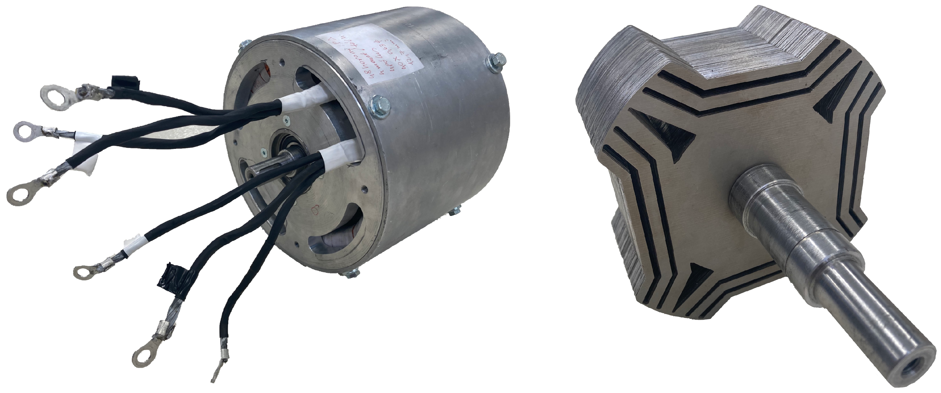
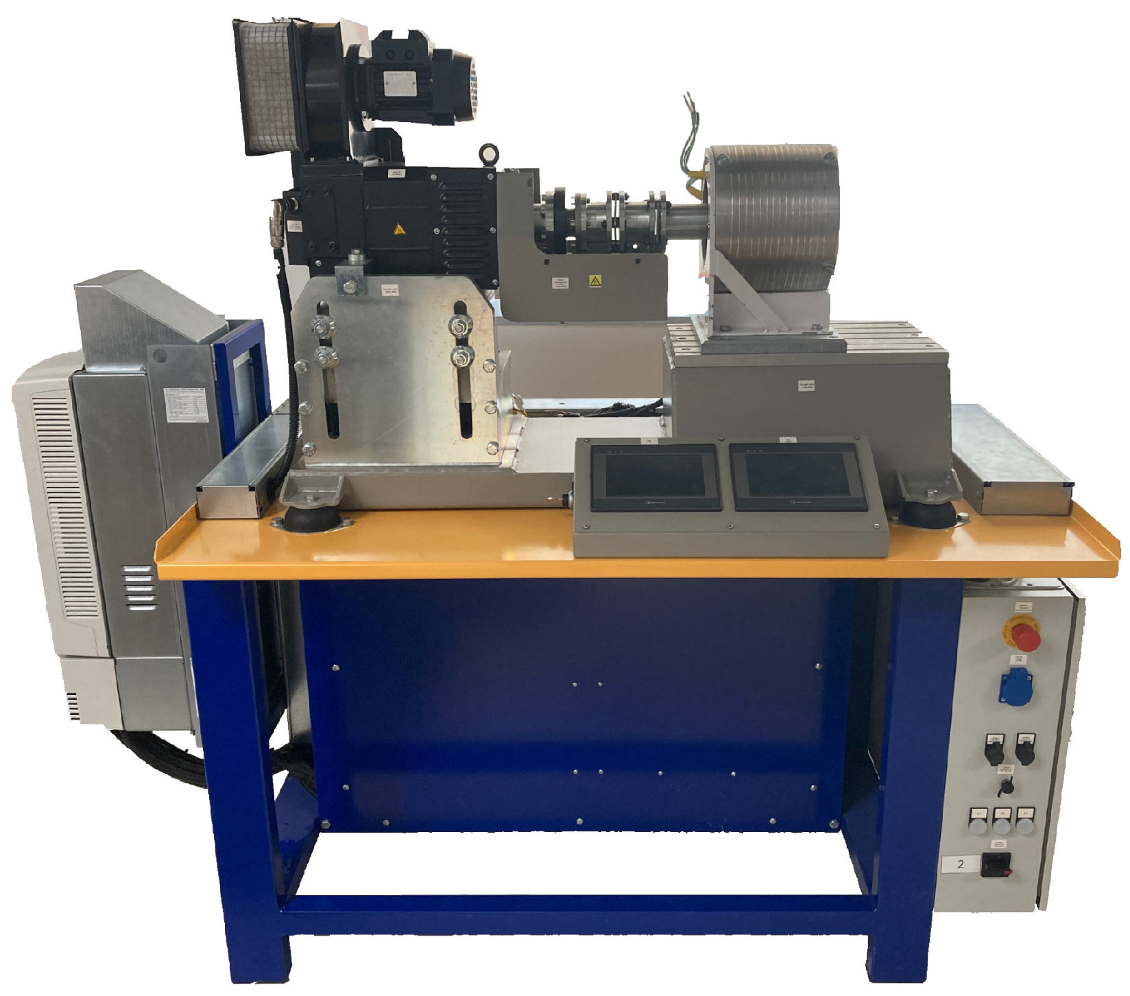
61]. The investigated electric machine, as presented in
Figure 1, is an experimental, Machaon-type synchronous reluctance machine without an active cooling system. Two identical electric machines were built with the same stator and rotor parameters. One was used for parameter identification and the other for control measurements. In addition, the geometry of the electrical machines was known from the blueprints, but the built-in iron core materials were changed during the manufacturing process. Therefore, the torque capabilities, the losses, the winding scheme, and the geometrical information were not precisely known. This section explains the necessary identification process steps to specify the winding scheme, geometry, and material characteristics of the investigated electric machine. The 2D CAD drawing of the winding scheme, the blueprint, the measurement data for the B–H curve for the iron material, and the 2D model of the machine’s topology can all be found
https://github.com/Toroid-project/SynRM/ (accessed on 6 February 2024). The measured models and the proposed papers will be available on the connected repository, and they are intended as an improving and openly accessible benchmark.
Table 1 summarises the identified parameters of the examined machine. The following rated parameters are examined in this paper: rated power (
), rated voltage (
), rated current (
), rated torque (
), rated speed (
) and power factor (
).
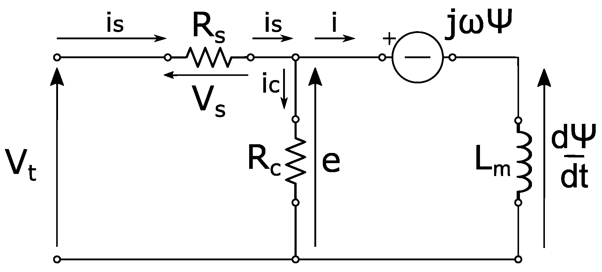
To approximate the equivalent circuit of a SynRM—i.e., the equivalent circuit of the PMSM that gives the basis of where the excitation caused by the magnets is left out—the following model can be used and derived, as shown in
Figure 2 and Equation (
1).
In
Figure 2, the signs note the following parameters:
: Terminal voltage [V];
: Armature current [A];
: Winding resistance [];
: Flux linkage [Vs];
: Electrical angular velocity [];
e: Back-electro motive force (EMF) [V];
: Rotor inductance [Vs].
The flux linkage (
) according to the armature current (
) can be defined as follows in Equation (
2) (where
is the totalwinding leakage):
As such, in the steady state
of Equations (
5) and (
6), the following can be used in a dq reference frame where the real part of the equation is the
d component and the imaginary part is the
q component:
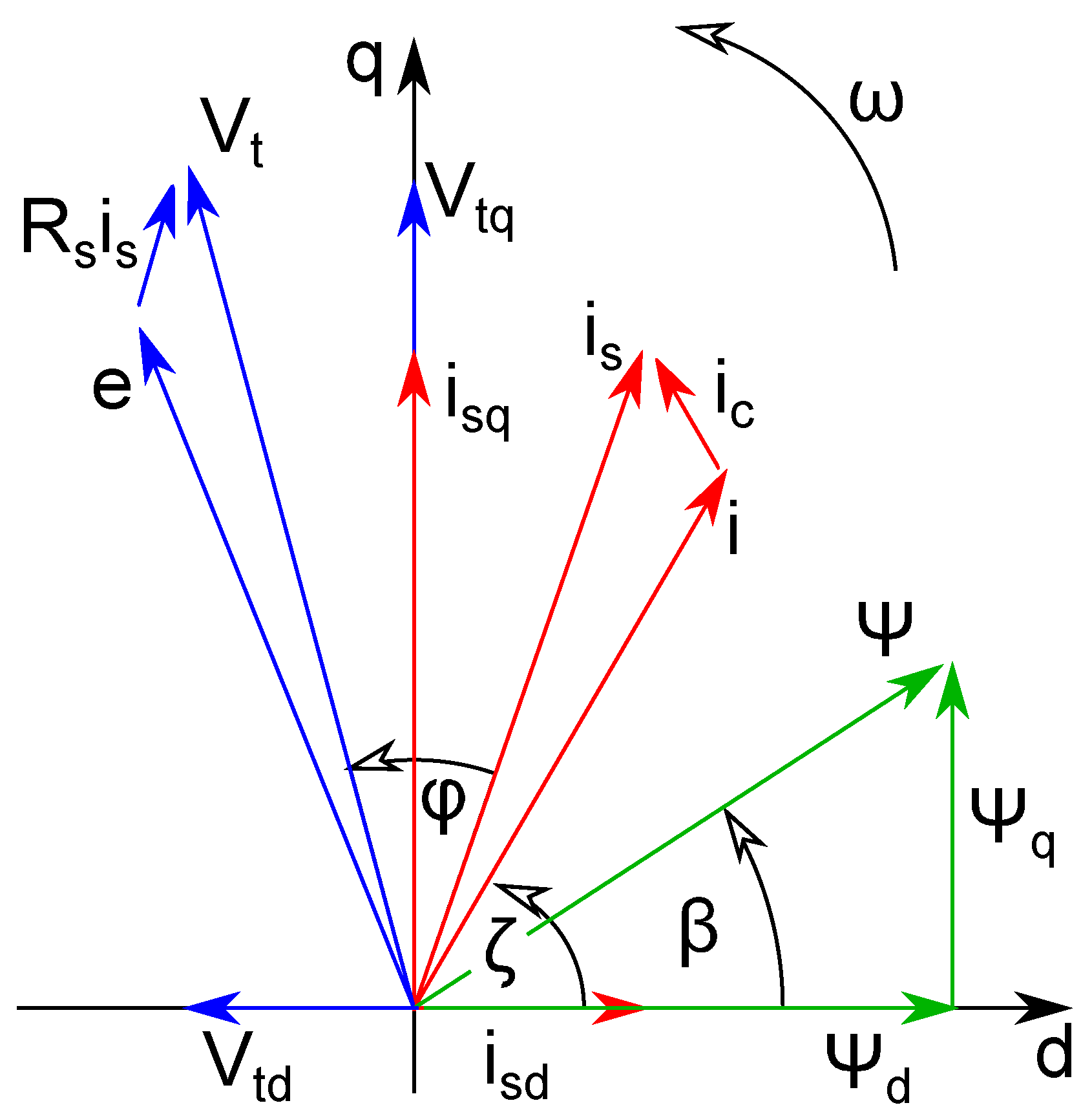
In
Figure 3, the vector representation of the SynRM motor is shown. As the SynRM operates as a motor, the electric circuit’s inductance is dominant, thereby resulting in the armature current lagging behind the terminal voltage by a phase angle (
). To reach an acceptable power factor and thus a wider constant power and speed range, it is required to create a high magnetic anisotropy
[
64].
2.1. Winding
According to [
46], the first step of the remanufacturing process is a preliminary inspection of the machine, i.e., visual inspection and thermal measurement. It should be supplemented with winding resistance measurement and whether there is a short circuit between the housing and the winding, or from phase to phase. In the case of the investigated electric machine, the resistance between one phase and the housing was measured between
at 500 V with an insulation tester device. Furthermore, the phase-to-phase insulation test had the same result. This suggested that there was no faulty insulation. On the other hand, as measured by a four-wire resistance tester, the copper winding of the machine had a notable discrepancy in the phase resistances. Specifically, the resistance of phase V was nearly half of the resistance of the other two phases. This could have indicated an underlying issue, such as a short circuit between the turns or faulty soldering between layers. It is important to address this matter promptly to ensure optimal machine performance. The measurement results are summarised in
Table 2.
The next step is to disassemble the machine using as much non-destructive methods as possible to maximise the quantity and quality of the reusable parts, such as housing, covers, shafts, and bearings. In this case, the machine was held together by bolts; as such, it was unnecessary to heat any part of the machine to loosen the tight bond between the parts. Focusing on the winding, the following parameters had to be determined for the simulation: the diameter of the enamelled copper wire, the number of slots per phase, the number of turns per slot, the number of parallel wires per turn, the winding scheme, and the winding pitch.
The wire diameter measurement results fell between 0.69–0.71 mm, which matched the range specified for enamelled copper wire with a nominal conductor diameter of 0.67 mm and were manufactured according to the IEC 60317-0-1 international standard [
65]. This wire was coated with cured resin insulation. For winding electrical machines, generators, and transformers, the IEC 60317-13 international standard [
66] specifies the use of polyester or polyesterimide that is overcoated with polyamide-imide-enamelled round copper wire of class 200 with a dual coating. Class 200 requires a minimum temperature index of 200, which translates to a guaranteed service life of 20,000 h at 200 °C [
67]. Based on these international standards, it can be assumed that the investigated electric machine’s winding was as per the specifications.
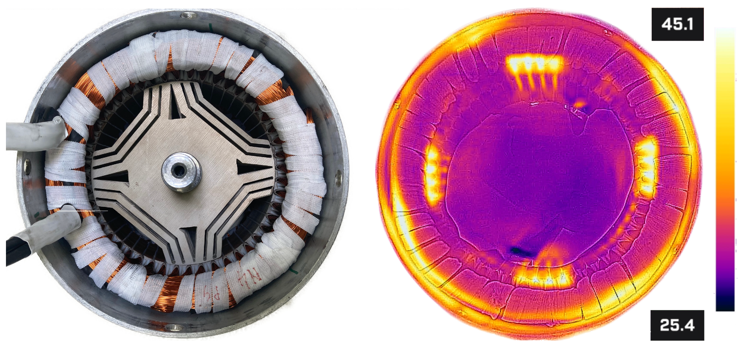
The number of slots per phase (
q) was determined by non-destructive thermographic imaging. In order to gain a comprehensive understanding of the winding pitch, a direct current of 50 A was applied to one phase for one minute. The thermal response was subsequently captured using a thermographic camera, and the resulting image is presented in
Figure 4. Analysis of the thermal image revealed that the winding exhibited no winding pitch, thereby indicating that a single phase fills an entire slot and the number of slots per phase is four.
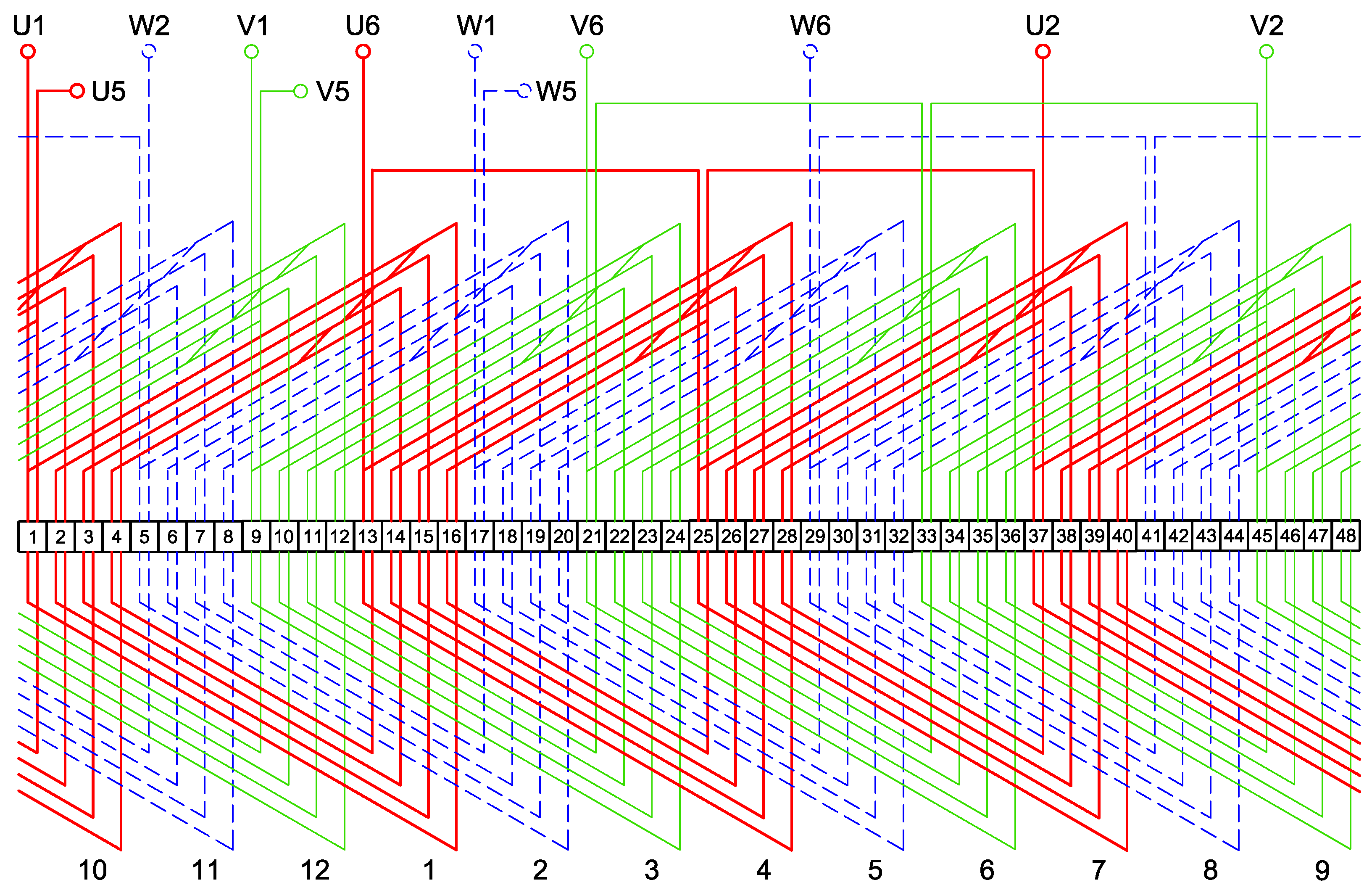
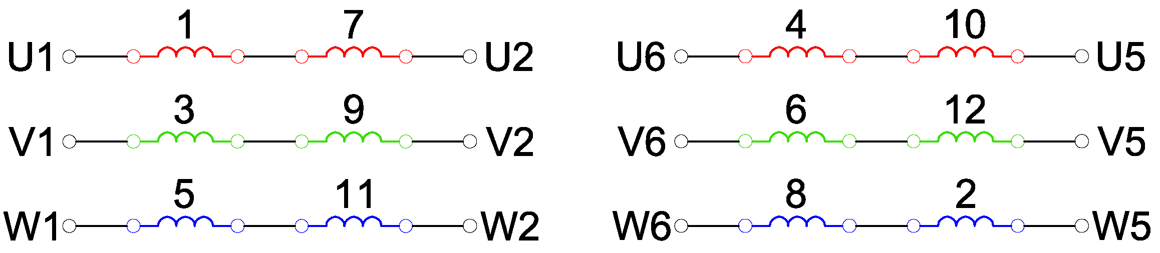
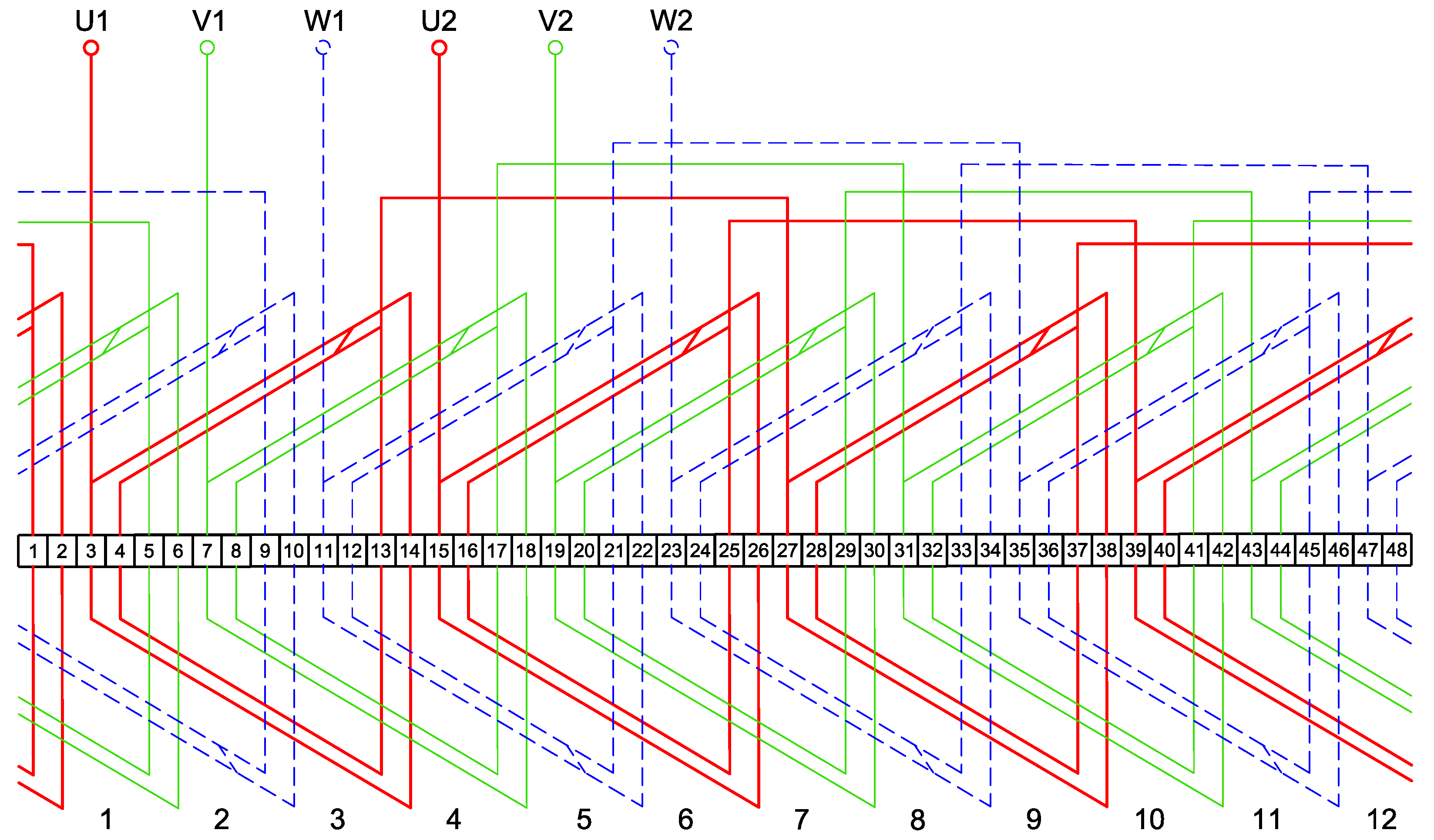
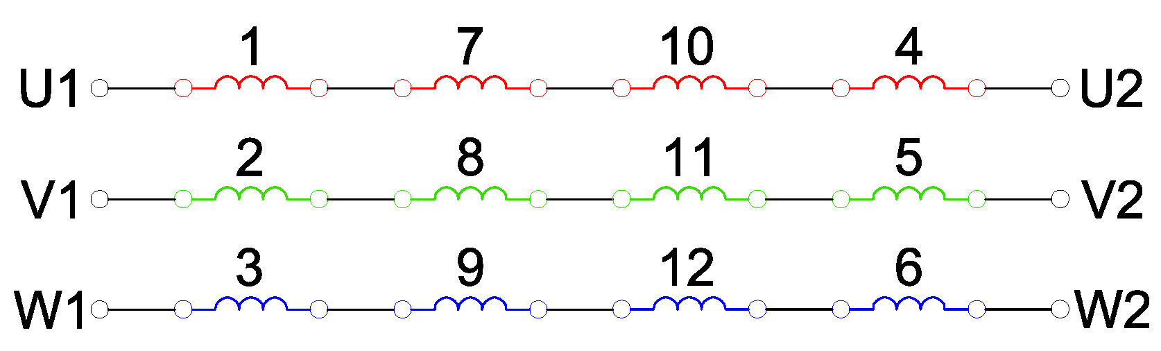
The number of turns per slot, parallel wires per turn, and the winding scheme were distinguished by closely inspecting one side of the winding heads extracted in its original state. It was possible by cutting through the wires close to the stator core as a destructive method. The winding could be recycled after removing the bandages and the insulation paper. From the winding heads, it was derived that it has two layers, four turns per layer, and twenty parallel wires per turn. Upon inspecting the soldering between the layers, the following winding scheme was depicted in
Figure 5 and
Figure 6. With this type of winding, it is possible to change the connection between the parallel and serial connections, and the winding heads were found to be smaller than in the case of a one-layered solution. The connection table is present in
Table 3.
2.2. Geometry
Li et al. [
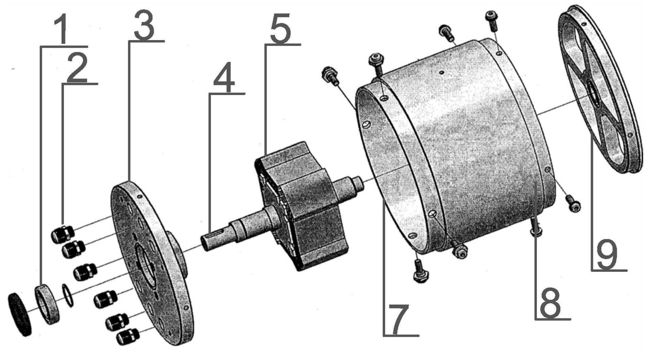
46] suggested that the second step is disassembling and classifying the parts into different classes as either reusable, remanufacturable, recyclable, or disposable for the purposes of remanufacturing. After the complete disassembly of the machine, the parts were compared to the blueprint shown in
Figure 7 and classified in
Table 4.
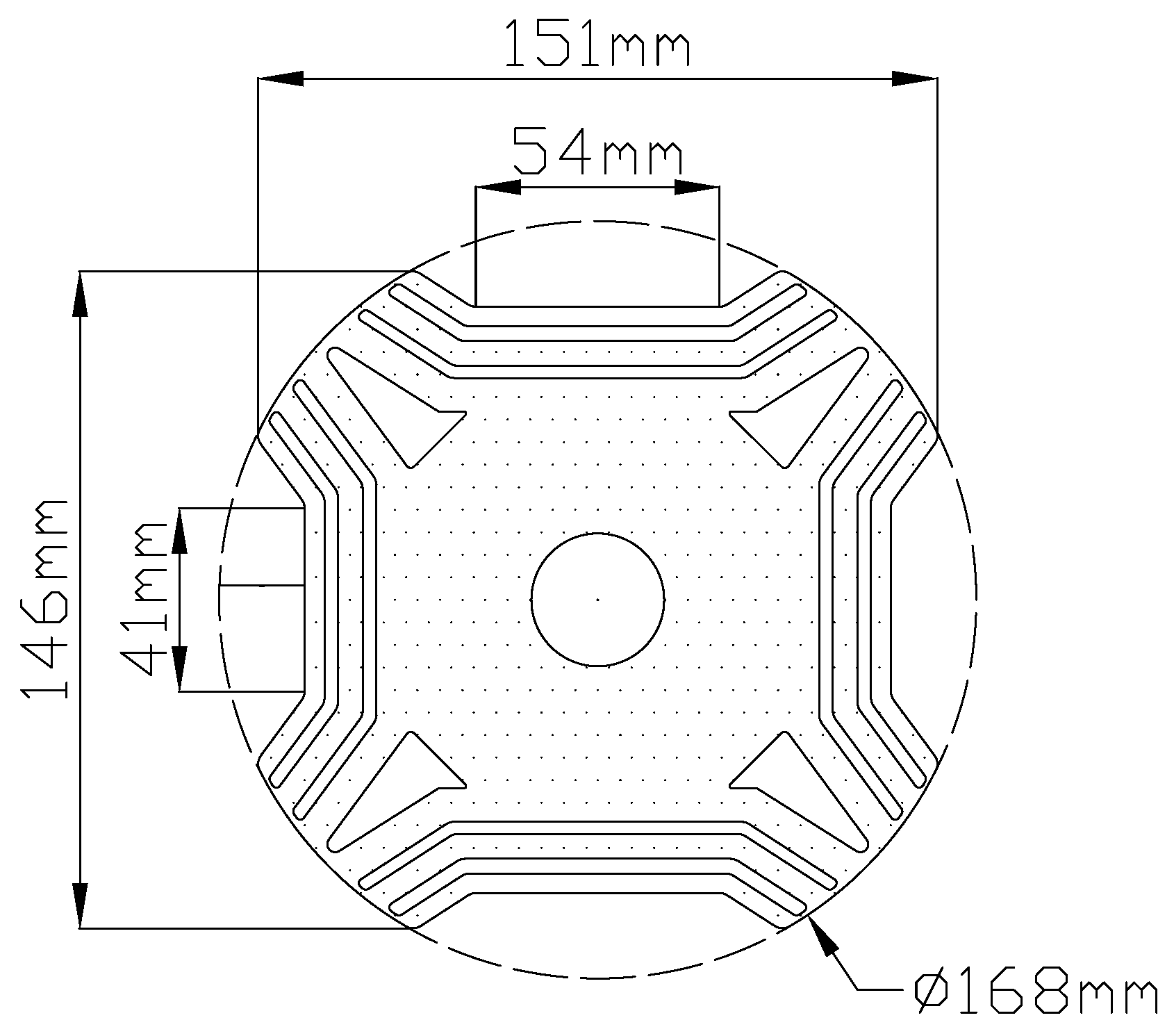
From a simulation and modelling point of view, the stator and the rotor geometry are the most important parts. The stator geometry was identified from the blueprints and confirmed through control measurements. However, there was a discrepancy between the realised laminate of the rotor and the blueprint. A high-resolution scanner was used to scan a laminate that was removed from the shaft to determine the rotor topology and its dimensions. This scan was then used to create a 2D vectorised drawing, as shown in
Figure 8, using Autodesk AutoCAD [
68], which was supplemented by manual measurements. Through a careful examination, it was found that the rotor is an asymmetrical Machaon-type structure with distinct flux barriers between adjacent poles [
69]. The stack length of the rotor was 78 mm, which was 8 mm longer than the stator stack length. The rotor laminates and the stator laminates were both 0.65 mm in depth.
2.3. Material Characteristics
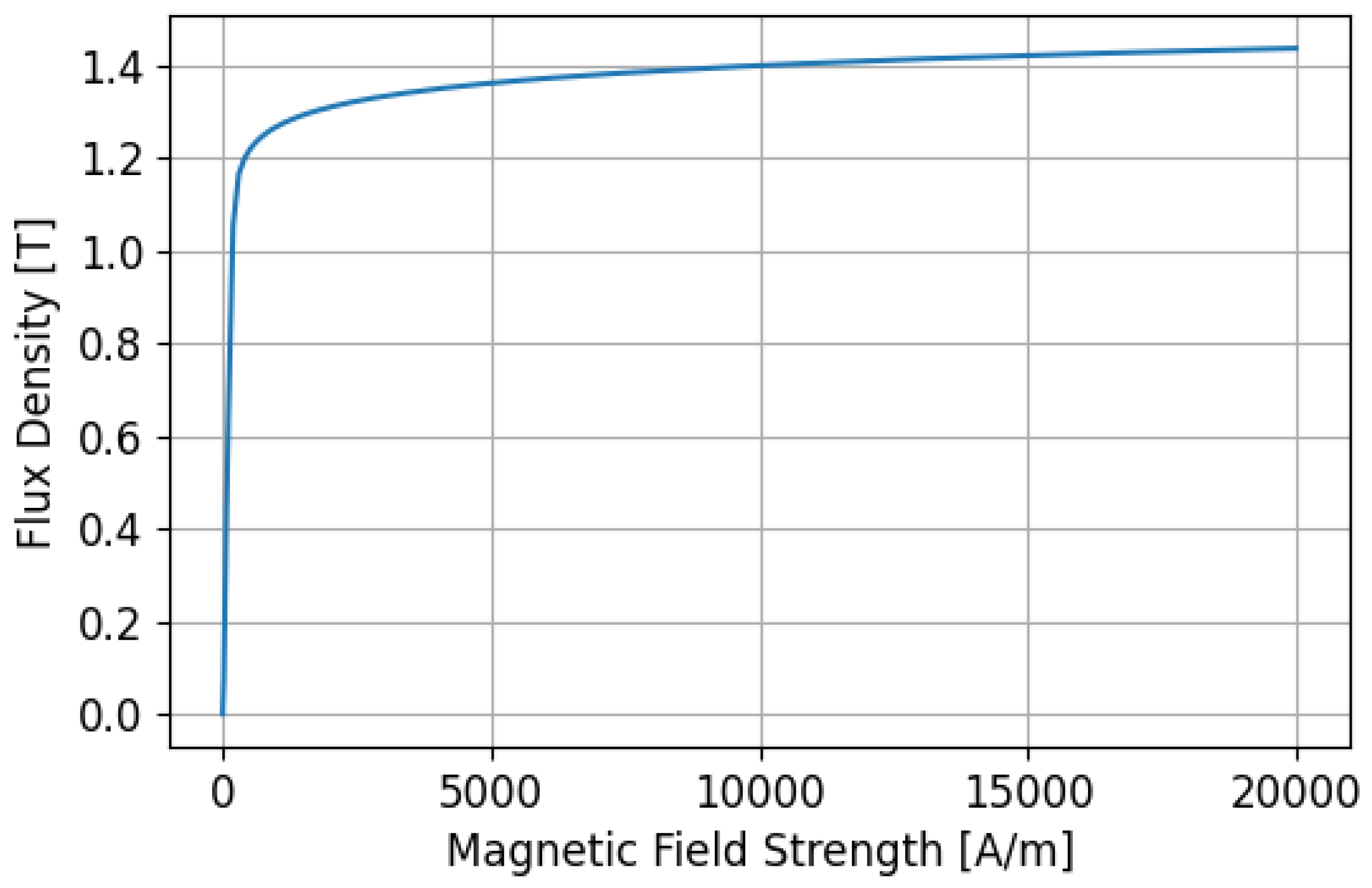
Another piece of crucial information for the modelling is the material characteristics. According to the blueprints, the S235 steel used for the iron core is a non-alloy carbon structural steel that is divided into different quality grades according to the EN 10025 standard [
70]. Because it is not considered electrical steel due to the absence of silicon, there is a lack of measurement results published in the literature (other than ref. [
71]). This being so, the studies of [
72,
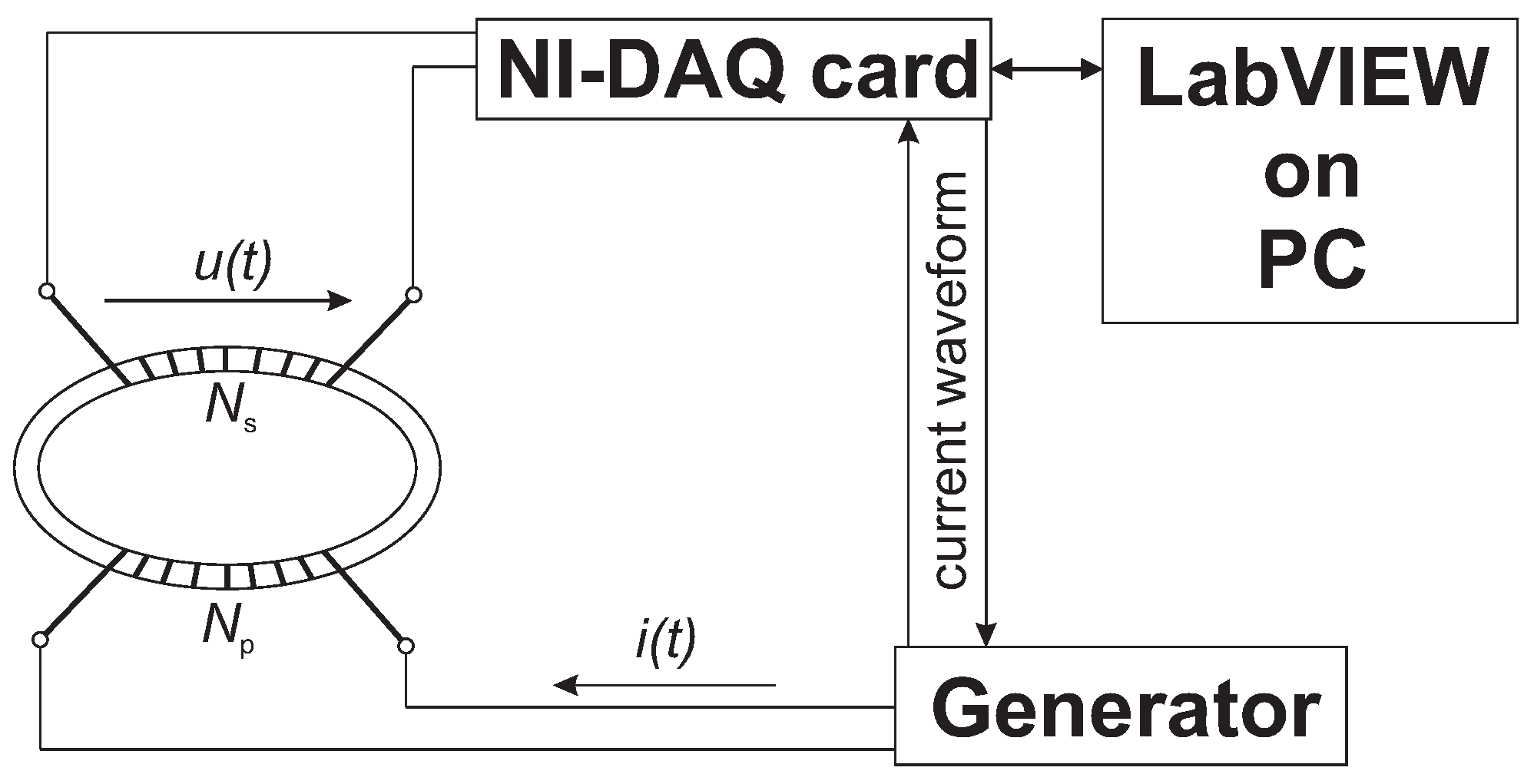
73] validated that a measurement process is used to obtain the B–H curve of a machine’s iron core. The scheme of a B–H curve measurement can be seen in
Figure 9. The laminated steel sheet has a primary excitation coil, which allows for the determination of the magnetic field intensity
by the exciting current with Equation (
7). The magnetic flux
can be determined from the induced voltage in the secondary winding with Equation (
8).
where
and
are the number of turns of the primary and secondary coil, respectively;
l is the mean length; and
S is the cross-section of the stator coil. As shown in
Figure 9, the excitation current signal
was transmitted to the generator using the National Instruments PCI-6251 type data acquisition (DAQ) card, which was connected to a PC. In order to validate the given current waveform, it had to be measured. The open-circuit voltage
in the secondary coil was measured via a DAQ card. The measurement environment, where the excitation signal was generated, was built in LabVIEW. The raw and refined data of the measurement can be found on [
74] and are shown in
Figure 10.
4. Static Torque Calculation
The analytical approximation of the torque capabilities was calculated by Equation (
10), where the inductance values were approximated from the results presented in
Section 3.2, which are then summarised in
Table 6.
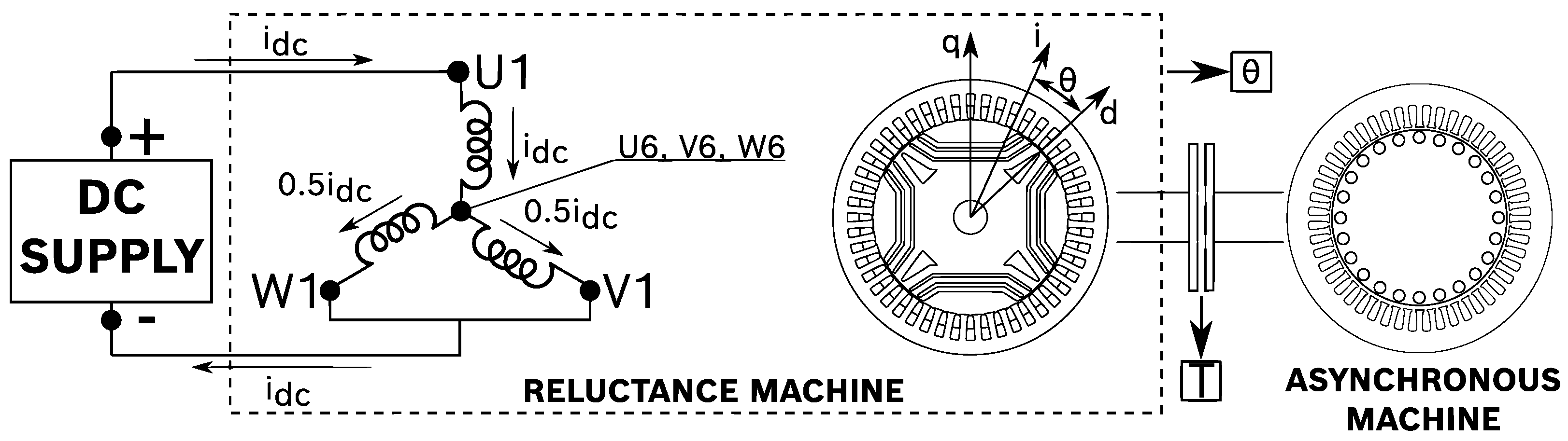
The currents were constrained, as depicted in
Figure 12. As the excitation of the machine during static torque measurement was constant during direct current, the phase values (in a three-phase system) were approximately as follows:
and
. Then, the current values were transformed into an
coordinate system using the Clark transformation written in Equations (
11) and (
12) [
78].
Lastly, the currents in an
frame were transformed to the
coordinate system using the angular position of the rotor (
), which was converted to electric degrees by
and derived from the static torque measurement using the Clark transformation written in Equations (
13) and (
14) [
78].
The finite element analysis model was created in a Digital-Twin-Distiller [
79] environment, which is a Python package for creating a long-lasting, encapsulated version of numerical simulations or machine-learning-based projects. For this reason, the parametric model was coded in Python language using PyCharm IDE, which is connected to the openly accessible GitHub repository [
74]. The parametric model, the measurements, and the simulation results are also stored there. The finite element solver used for the simulations is finite element method magnetics, an open-source suite of programmes for solving low-frequency, linear/nonlinear magneto-static problems on two-dimensional planar and axisymmetric domains [
80]. The data and information gathered in
Section 2 make the modelling possible. Firstly, a 2D drawing of the stator geometry in .dxf format was imported into the model derived from the machine’s blueprints. Secondly, a 2D drawing of the rotor geometry was also imported and derived from the high-resolution scan in .dxf format. The drawings were created in AutoDesk AutoCAD [
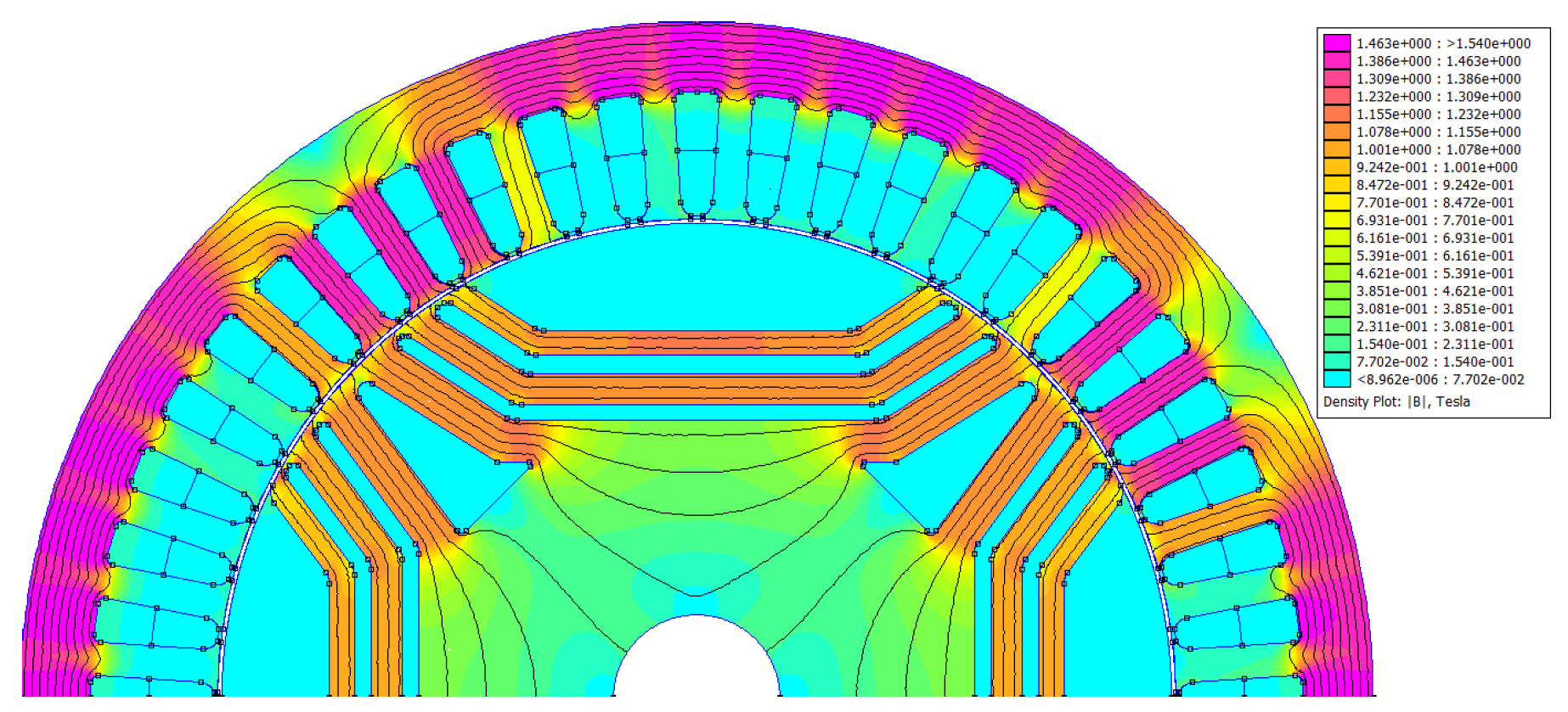
68]. In order to decrease the computational capacity needs of the model, half of it was built up using periodic boundary conditions, as shown in
Figure 15. Because of the geometrical difference between the two adjacent poles of a Machaon-type machine, the simulation of only one pole is not possible. The rotor and stator geometries were connected using a periodic air gap boundary condition [
80], allowing torque evaluation to be carried out in different rotor positions without transforming the geometry. The winding of the machine was modelled as identified in
Section 2.1 using a symmetrical, three-phase scheme with four slots per phase (
), where
U,
V and
W are the phases of the machine.
The material block representing the copper winding filled the whole slot with linear material properties of
, with an electrical conductivity of 58 MS/m. The DC excitation was set using source current density (
J). As presented in
Figure 12, if
= [15A…35A];
= 142.793 m
; and
and
in Equation (
15).
The material block representing the iron core was defined with non-linear material properties by setting the B–H curve to the results of the measurements described in
Section 2.3 and presented in
Figure 10. The iron core material was laminated in-plane, with a lamination thickness of 0.65 mm and a fill factor of 0.98.
One possible measurement that can be simulated focuses on the static torque, as proposed in
Section 3. In the simulations, the torque was evaluated at various rotor positions, spanning from
to
, with incremental changes of
in mechanical angles. The excitation represents constant DC excitation, as depicted in
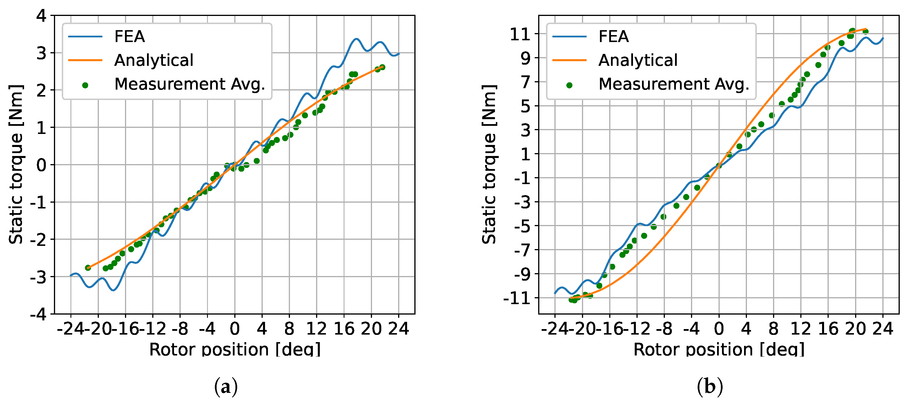
Figure 12. The models were evaluated at different current amplitudes—spanning from 15A to 35A, in increments of 5A—similar to the measurements. The model and static torque approximation were compared to the measurements covered in
Section 3 and presented in
Figure 16a,b.
The analytical approximation is closer to the measurement results at lower currents. A possible cause of this difference is that the inductance measurement did not cover the saturation effect at high currents. On the other hand, finite element analysis approximates the measured torque at an acceptable level at both lower and higher currents. Furthermore, it shows better accuracy at higher currents. This comparison confirms the correctness of the identification process. With the FEA model created, the redesign of the rotor from synchronous reluctance to ferrite magnet-assisted synchronous reluctance is possible and this redesign continues the remanufacturing process from the remanufacturing solution design step defined by [
46].
5. The Rewinding Process of the Electric Machine
The first step in the realisation of remanufacturing the investigated electric machine is rewinding. For later research purposes and to compare different rotor topologies with aluminium- and copper-wound stators, the investigated machine was rewound using aluminium wires, which were 1.6 mm in diameter. To accurately compare the two types of stators, the aluminium winding scheme has the same properties—meaning that it has the same number of turns and slots per phase, as well as being connected in serial—as shown in
Figure 17 and
Figure 18. There are four parallel wires in one turn. An increase in wire diameter also causes an increase in the slot filling factor (
f), which is calculated by Equation (
16), where
n is the number of parallel wires per turn. The slot filling factor for the 0.63 mm copper winding is
, but that of the 1.6 mm aluminium winding is
. This means that there is a 20% difference in phase resistance, although aluminium has only 61% of the conductivity of copper. The measurement results for the remanufactured aluminium-wound machine are summarised in
Table 7.
Because of the increased DC resistance, it was also expected that the DC losses of the machine would be higher as in the case of the initial machine. Nevertheless, considering micro- and e-mobility applications, the speed range, where the electric machine was expected to operate, was found to be at a higher frequency. The losses of electric machines—excluding mechanical losses such as friction or ventilation—were calculated by summarising the DC and AC losses. Specifically, the winding losses at a high-frequency range were expressed as a combination of the DC loss (
, which was only affected by the amplitude of the applied current (
I) and the DC resistance (
R) skin and proximity effects, and the circulating current effect that was caused by uneven current sharing via the strands is shown in Equation (
17) [
81,
82]. When alternating current flows through a conductor, the current density near the surface became greater than that in the core because of the generated eddy currents, which is known as the skin effect. Proximity effect loss is the losses in a strand that occur due to an external magnetic field that is generated by surrounding strands. Under load conditions, armature field flux can leak into the slot, thereby causing an inductance imbalance between the bundle strands and generating circulating currents. The AC loss depends on various factors, including conductor dimensions, as well as due to the frequency and amplitude of the magnetic field [
82].
Bardalai et al. [
82]. showed that circulating current losses are less than 10% of the total winding losses with four parallel conductors, as was the case in the investigated aluminium-wound machine. Because of this, the loss due to circulating currents between the parallel coil paths was considered negligible, as was the case in the work of Widmer et al. [
83]. The eddy current loss can be more precisely approximated by the axial (
) and radial (
) components of magnetic induction when using the FEM-based magnetic field calculations that were presented in [
84,
85]. The axial and radial components of the eddy current loss for rectangular-shaped conductors are shown in Equations (
19) and (
20). It is important to note that the amount of the eddy current loss is in a inverse proportion to the specific resistance (
) of the conductive material as follows:
where
is the angular frequency, and
d and
h are geometrical parameters. As the specific resistance of the aluminium was found to be 64% higher than copper, the eddy current losses were expected to be lower.
The 20% difference in DC resistance was significantly lower than the gradient of the AC/DC loss ratio at different frequency levels; this analysis was based on the study of Selema et al. [
86], who investigated eddy current losses in the windings of high-speed and high-frequency electric machines. The focus was on AC winding losses, whereby copper and aluminium conductors were compared for the same winding design. The study used FEM to simulate conductor loss and current density, as well as verified the simulated losses through AC loss measurements over a wide frequency range. The AC/DC and loss ratio difference exponentially increased after the break-even point at approximately 300 Hz in favour of an aluminium winding. The study by Ayat et al. [
16] examined the performance of an interior-mounted permanent magnet electric machine using aluminium winding. It compared a machine with copper conductors, and the impact of using aluminium was also explored. The study showed that aluminium conductors can be a viable alternative, particularly for large cross-section conductors that often suffer from elevated AC losses. The analysis accounted for factors like magnetic saturation and stator current vector, and the use of a hardware prototype provided reliable predictions. As presented, aluminium has a higher electric resistivity than copper, thus making it less susceptible to AC losses. This enables an increased slot filling factor in aluminium windings when compared to their copper counterparts. The improved slot filling factor compensates for higher levels of DC loss. The results indicated a slightly lower continuous output performance observed at low speed and high torque, particularly in the case of windings made with aluminium conductors. However, the impact on average efficiency over the one investigated duty cycle appeared to be relatively low, i.e., around 1.9% at best. Based on the study, the overall efficiency was expected to be comparable to the original electric machine, and rewinding was not expected to significantly reduce the number of possible applications.
From an economic point of view, rewinding the electric machine with a 1.6 mm diameter aluminium winding had an overall cost of EUR 342.66, including disassembly, rewinding, insulation, control measurements, and assembly in this particular case. The breakdown of the costs, which is presented in
Table 8, was achieved by assuming the contribution of different cost categories to the overall costs for different production volumes as defined by Hemsen et al. [
87]. The study of [
87] presented a cost estimation model that can be used to determine the production costs of electric machines, thereby providing the flexibility to modify various design choices such as wire technology, winding layout, cooling system, materials, and other such factors that can impact the production costs. This paper used the model presented in [
87] to approximate the remanufacturing costs, which are presented in
Table 8. As only one unique electric machine was remanufactured, small-volume production was considered. The material cost difference between copper and aluminium was approximated with the data and calculation method that was published by Vajsz et al. [
17]. Using aluminium instead of copper reduces the weight of the winding by almost half, and this is despite the need to increase the conductor cross-section to maintain the same wire resistance. Suppose there is a 20% resistance difference between the initial and the rewound machine. In this type of case, the equations have to be modified in such a way that the cross-section of aluminium is 20% less if the specific resistivity and the overall length of the wires are assumed to be the same.
Based on the market prices used by Vajsz et al., the total cost of winding when using copper and aluminium was found to be significantly different [
17]. The cost of winding when using aluminium was only 12.48% of the cost of winding when using copper, which also had similar results to the calculations of Ghahfarokhi et al. [
88]. The price difference between copper and aluminium is expected to change significantly in favour of aluminium in the coming years. The other contributors, such as equity, tool cost, labour cost, etc., are assumed to be similar in the two cases.
6. Conclusions
In this paper, the identification process of an experimental synchronous reluctance machine for remanufacturing purposes when there is a lack of information about the properties of a machine was presented. The proposed remanufacturing processes might be applied to any type of electric machine that is similar to an extent with the investigated three-phase synchronous reluctance machine, such as—for example—permanent magnet synchronous machines or asynchronous machines. However, every type of electric machine has unique characteristics; as such, further measurements might be added, like the magnetic field measurement of a permanent magnet, or the simulation methodology could differ as in the case of an asynchronous machine. In terms of scalability, the available equipment for the measurements determines the identification possibilities to a large extent. Although studies are considering high-power industrial electric machines, future research should—as the current study has—focus on low-power electric machines, which might be a possible application for micro- and electro-mobility. In the case of an unknown, unique electric machine, or even in cases were not all of the information is known about it, redesigning can be difficult. Methodologies are needed to classify a machine’s mechanical state and identify those material characteristics, winding schemes, etc. This paper supplements those and shows possible ways through which to determine a machine winding scheme, as well as its parts, geometry, and material and electro-mechanical characteristics. Some case studies have also been presented in the aim of pursuing the establishment of a standard remanufacturing process for electric machines. This study implies that, in the case of remanufacturing electric machines, standardising the identification of important parameters for 2D or 3D simulation is recommended. None of the studied legislations cover the identification processes of existing electric machines. This might be because of increasing component specificity, protectability, and strict property rights. Instead, EU regulations have recommended “design for remanufacturing”. Pending the market’s transition to a circular economy, the remanufacturing of electrical machines that are already in circulation also requires the regulation of identification processes to increase product quality and strengthen customer acceptance.
Furthermore, this paper provides the measurement data, topology, and finite element analysis model that was applied in a solver called Finite Element Method Magnetics wrapped in Digital-Twin-Distiller as an open benchmark dataset for those researchers who are pursuing their novel numerical methods for electric machine design, optimisation, and remanufacturing. The rewound machine has a 20% higher DC resistance but also a 29% slot filling factor. The overall losses of the rewound machine are expected to be lower than those of the initial machine, especially at higher frequencies. Based on the considered economic model, rewinding with aluminium costs 39.5% of the cost of when rewinding with copper. In further research, the parameters of the rewound machine will be measured and compared to the original motor.


