Abstract
The design of a wireless power transfer system with double rectangular coils for 11 kW power transfer is considered. System modeling and numerical calculation of the system parameters are described. Coils are made from available Litz wire, which has a smaller than necessary diameter for the required power. Thus, a setup with double layer coils was developed, which resulted in a modified design. Starting from a system consisting of coupled coils, as suggested by the standard for wireless power transfer Level 3 in class Z1, different coil and ferrite shield layouts were tested in numerical simulations, and their parameters were calculated. The prototype was constructed based on the simulated model with the best results and properties. Numerical results were verified by laboratory measurements, and a successful power transfer at 11 kW was achieved.
1. Introduction
Various physical principles can be employed in realization of wireless power transfer (WPT) systems. The power transfer can be obtained by inductive coupling, capacitive coupling, or microwave radiation [1,2,3,4,5]. Low-power charging is widely used in mobile and wearable devices, smart home appliances, smart textiles, and medical implants [6,7,8,9,10,11]. A different set of challenges emerges in high-power wireless charging applications, such as electric cargo and passenger vehicles, ships, airborne vehicles, unmanned vehicles (drones) and space vessels [12,13,14,15,16,17]. A significant breakthrough in the field of electric vehicles comes with the advance of autonomous and automatic charging without human intervention [18].
The design requirements and principles for high-power WPT systems, such as power level classes, frequency ranges, distance classes, reference pad models, maximum stray field levels etc. are defined by international regulations. The most used standards are the SAE J2954 and IEC 61980 [19,20,21]. Power level classes WPT1-WPT3 are defined with respect to maximum input of 3.7 kVA, 7.7 kVA and 11.1 kVA in SAE J2954 from 2019 for light-duty (LD) electric vehicles [19]. Power classes WPT1 and WPT2 align with the maximum power requirements as specified in SAE J1772 for AC Levels 1 and 2 charging, while WPT3 aligns with the European three phase outlet rating at 11 kW. Minimum target efficiency at nominal xy alignment is greater than 85%. In SAE J2954/2 from 2022 for heavy-duty (HD) electric vehicles, further power level classes WPT4-WPT9 are defined, corresponding to power in the range from 20 kW to 500 kW [20]. Classes Z1-Z3 define distances between primary and secondary coils, at the ranges of 100–150 mm, 140–210 mm and 170–250 mm, respectively. Frequency ranges of 22 to 25 kHz and 79 to 90 kHz are used for static WPT, and frequency range from 79 to 90 kHz is used for dynamic WPT. Classifications for LD vehicles from standard SAE J2954—2019 [19] and for HD vehicles from standard SAE J2954/2—2022 are given in Table 1.

Table 1.
Classifications for LD vehicles from standard SAE J2954—2019 [19] and for HD vehicles from standard SAE J2954/2—2022 [20].
Several criteria for comparison of designs of inductive power transfer for contactless electric vehicles chargers have been considered, such as magnetic coupling factor, quality factor, power efficiency and power losses in wire windings and ferrite cores. Of interest are also various coil geometries (topologies), as well as different compensation schemes and impedance matching circuits. Some papers focus on electromagnetic compatibility (EMC) [22]. A review of some magnetic couplers can be found in [23,24,25]. Many papers deal with coil geometries: circular, square, rectangular, double D (DD), double D quadrature (DDQ), bipolar, tripolar. Based on different requirements and testing conditions, various authors reached different conclusions [23,24,25,26]. For example, in [27,28], based on a study of three shapes, circular, square, rectangular, the authors conclude that the coupler surface area is more important than the shape itself. Optimizations aim to maximize efficiency, volumetric power density, gravimetric power density, and misalignment tolerance. Depending on the choice of geometry and optimization priorities, different amounts of shield materials are required. For example, in a comparison between four topologies (circular, rectangular, DD-DD, and DD-DDQ) it was found that circular has the best efficiency and coupling factor, but it uses the most ferrite and least copper for the same performance. Ferrite arrangements were also explored in [29]. To ensure a fair comparison, magnetic couplers should be optimized under the same constraints. A comprehensive discussion on the subject can be found in [23]. DD and square coils exhibit a larger coupling coefficient than circular and rectangular ones. DD pads have also been shown to offer better contribution to the flux in the central region of the coupler. [23,30,31].
The power transfer efficiency for various coil designs was investigated in [31,32,33]. Improvements of the efficiency were considered regarding the air gap length, operation frequency, suitable coil designs and coil properties [31]. The efficiency of the DDQ design was found to be better in comparison with the circular, rectangular, double-D and bipolar designs, but DDQ structure is complex and requires more wires [31]. The variation in the coupling coefficient for different coil configurations and the influence of ferrite cores with a square coil on the coupling coefficient are discussed in [32].
Different compensation schemes and impedance matching circuits are discussed, classified, and critically compared in [34,35,36,37]. An increased number of passive components can cause extra loss [38,39,40,41]. Serial-serial (S-S) compensation with hybrid compensation topologies are compared in several papers [38,39,40,41,42]. In [38], it is demonstrated that the S-S topology possesses higher efficiency than the LCL-S topology. Hybrid systems based on the inductance and double capacitances-series (LCC-S) compensation topology provide simple structure, easy controllability, and stable output [39,42].
This paper is organized as follows: Section 2 describes the system requirements, models, and provides theoretical framework. Section 3 contains numerical results from the finite element model simulations on the considered models and the discussion of the results. Section 4 presents the experimental results, and the conclusion is given in Section 5.
This paper describes a design of a wireless power transfer system for electric vehicle (EV) battery charging, with a DD topology, coil and ferrite shield design, misalignment considerations, determination of parameters for the inductance and (LCC-S) compensation, prototype design and experimental validation. Coil geometry is studied and optimized, as it affects efficiency and limits the maximum charging power. The main contribution of this study is a developed design of the double-layer coils for WPT and a corresponding ferrite tile arrangement under the specified design requirements, including materials specification and the desired power levels. A parametric 3D model of the system was created, and the influence of parameter variations was examined. The effects of the system geometry and coil misalignment on the resulting magnetic field, inductance and magnetic coupling are presented graphically and discussed. Finally, a prototype system was manufactured, and a successful power transfer was conducted.
2. System Description, Modeling, and Theoretical Background
An electric vehicle charging system is considered, which consists of a transmitter (Tx) assembly placed above the vehicle, and a receiver (Rx) assembly placed in the vehicle roof.
The proposed system is designed to operate at the WPT3 level (11 kW), at a center operating frequency of 85 kHz and a Z1 class coils clearance distance of 100 to 150 mm. It consists of wireless charging coupling coils with LCC compensation on the primary side and series compensation on the secondary side. The design, modeling and experimental verification of the system are presented.
The primary and secondary coils are of different sizes. Due to space and weight considerations, the secondary coil is smaller than the primary coil.
Design specifications mandate the dimensions of the Tx coil at 630 mm × 580 mm and the Rx coil at 302 mm × 266 mm. The coils are constructed with Litz wire with a 6.3 mm2 cross section and 800 strands at the 0.1 mm nominal diameter.
The system consists of the transmitter and receiver coils placed in parallel, at a specified clearance distance. Coils are sandwiched between ferrite plates, followed by aluminum plates. The ferrite layer is constructed from ferrite plates 100 mm × 100 mm × 6 mm and 100 mm × 100 mm × 12 mm, which were mandated by design specifications. Aluminum plates are 870 mm × 870 mm × 4 mm.
The system should be following the standard regarding power levels, airgap separations, and overall system dimensions. The materials used were subject to availability and design specifications.
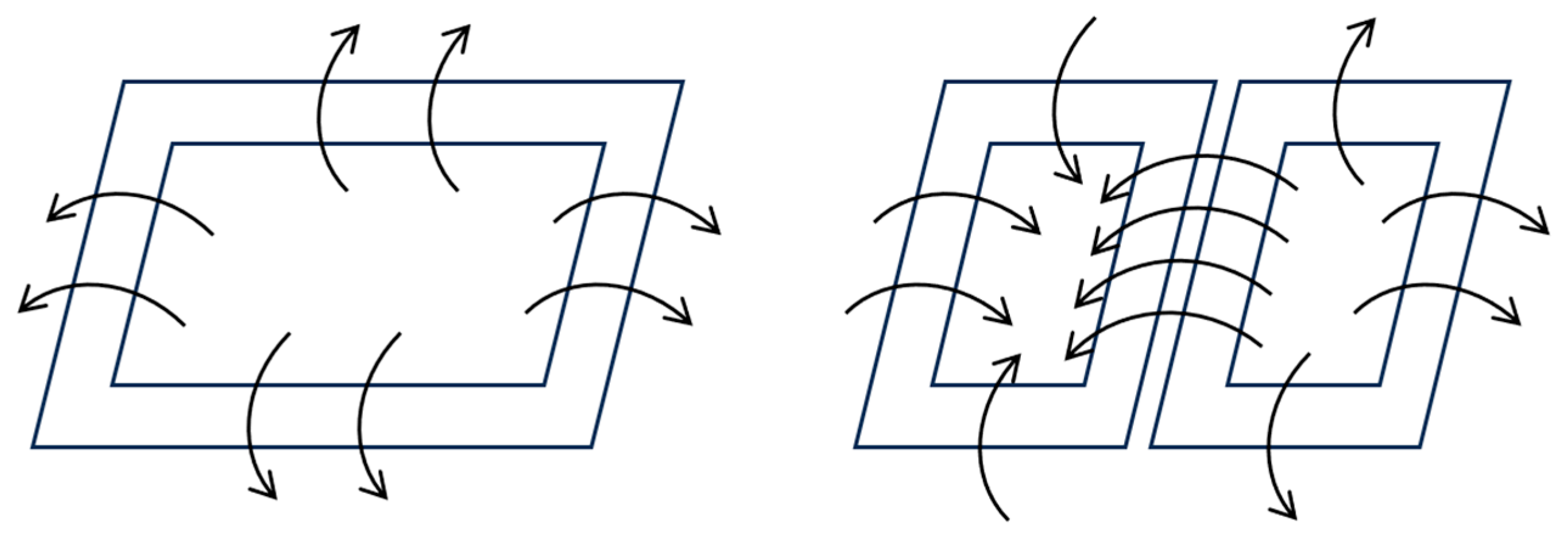
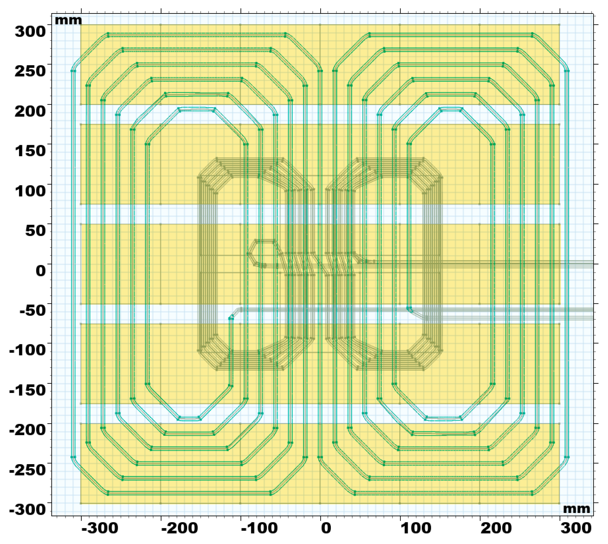
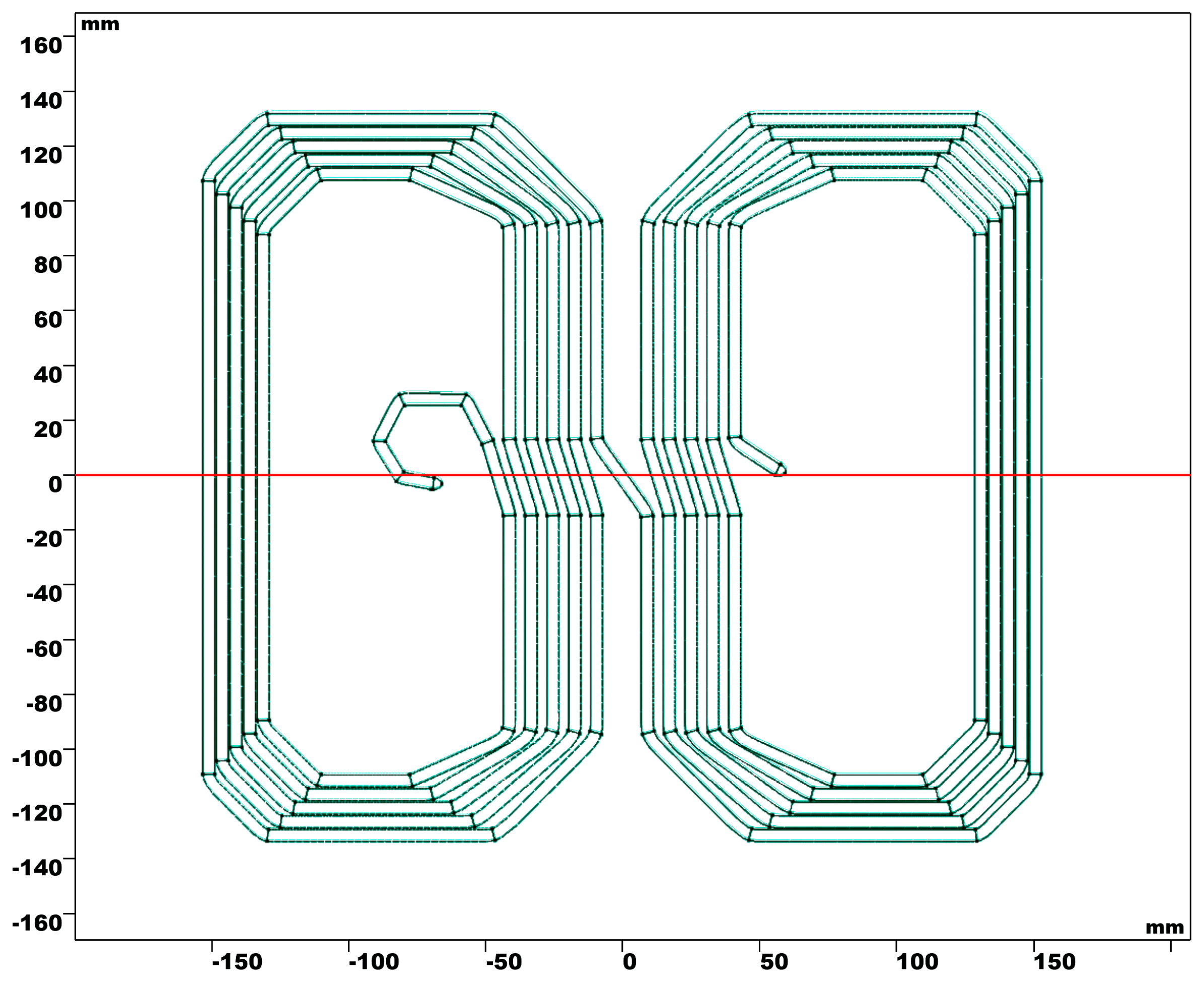
The transmitter coil is in the DD configuration (Figure 1a and Figure 2). The receiver coil is also in DD configuration (Figure 1b). Due to the power transfer requirement, the current intensity is too large for the specified wire cross section. For that reason, two wires were used instead of one, to increase the total cross section. The standard for the chosen power levels recommends a specific shape and size of planar coils [19]. However, the coils could not be designed with two colinear wires in a single plane since they would not fit into the available space. Furthermore, Tx coil’s magnetic field lines would not properly align with the Rx coil, which would yield an unsatisfactory magnetic flux. To remedy this, conducting wires had to be arranged in more than one plane, the proper arrangement of which had to be determined.
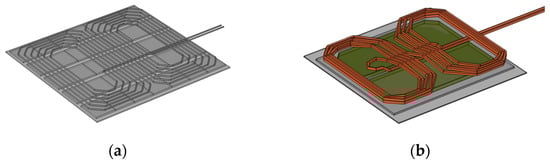
Figure 1.
(a) one layer Tx coil from model S, (b) one layer Rx coil from model S.
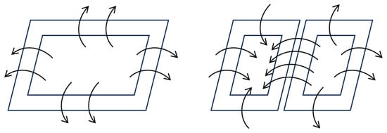
Figure 2.
Magnetic field lines near a rectangular coil and a DD coil.
The dimensions of the transmitter component of the system increases only marginally when a multilayer wire arrangement is used. In other words, the size increase is significantly less than when using two colinear wires in a single plane. Thus, two- and three-layered coils can offer an increase in the magnetic flux, with only marginal increase in dimensions. With an increase in the number of layers, the homogeneity of the magnetic field within the space between coils also increases, as the Tx coil starts to resemble Merritt and Helmholtz coils, commonly used to obtain homogenous magnetic fields [43].
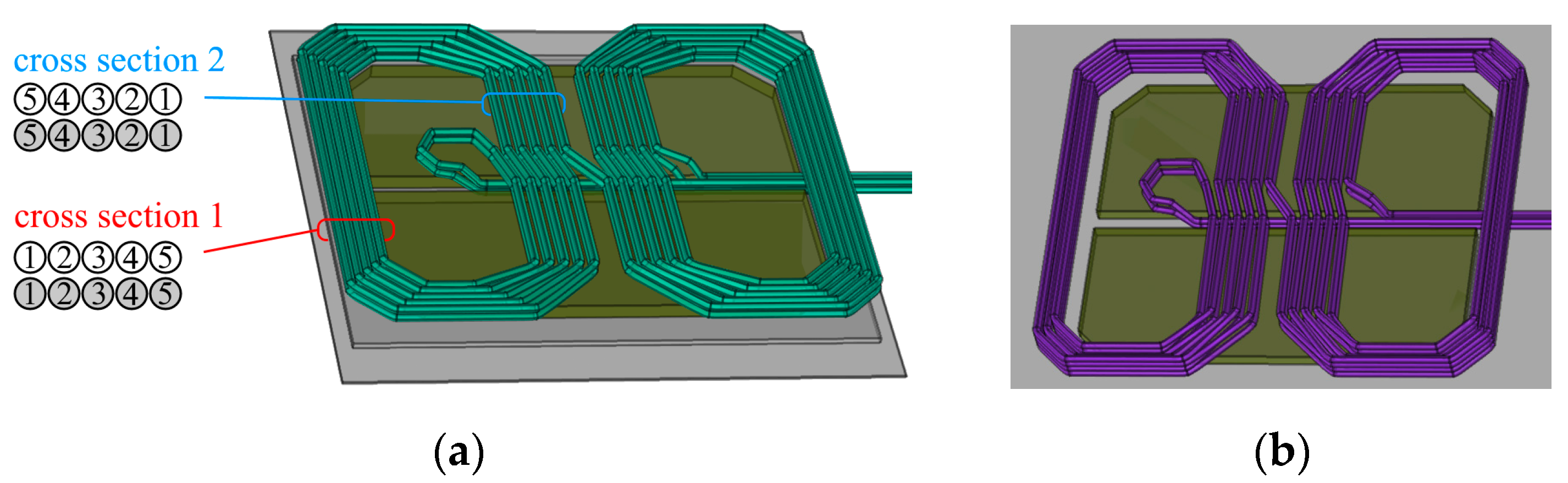
Several coil models with different multilayer wire arrangements were studied. Two models, A and B, are shown in Figure 3 and Figure 4, with each of the two colinear wires marked with a different color. Coil model A has the same two-layer cross-section at both sides (Figure 3a). Coil model B has a four-layer cross-section at the outside part of the loop, while the inner part is in two layers (Figure 3b). The corresponding cross-sections are shown in Figure 4a and Figure 5b respectively. One of the additional cross-sections is shown in Figure 4c. The layout of the model C is similar to model B, except the cross-section of the outside part of the loop is different, Figure 4c.
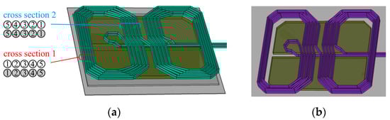
Figure 3.
(a) Conductor cross section arrangement for Rx coil in model A, (b) Rx coil in model B.
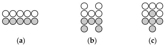
Figure 4.
Conductor arrangement in cross section 1 in (a) model A, (b) model B, and (c) model C.
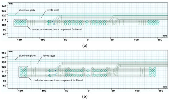
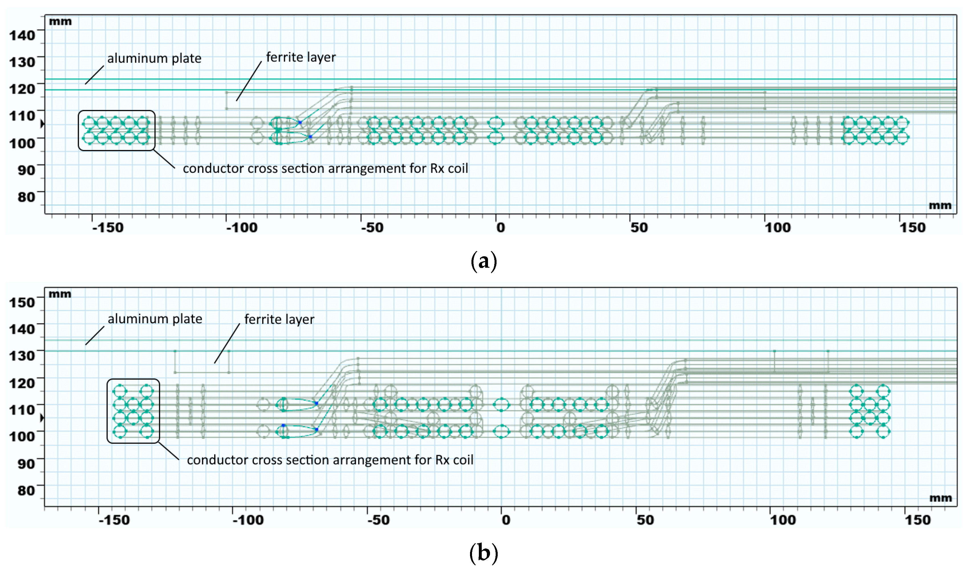
Figure 5.
Cross section of Rx assembly in plane y = 0 for (a) model A and (b) model B.
The system was modeled in 3D and simulated using the FEM analysis in COMSOL Multiphysics 6.0 software. To minimize CPU time and memory consumption, 2D simulations are used to simulate simpler models. However, the coil models in this analysis had to be created in three dimensions, because of their complex nature. Details of Rx assembly cross section are shown in Figure 5.
Models A, B and C were used to investigate the effect of wire layout on inductive power transfer. For this reason, the number and layout of ferrite tiles was fixed and identical in all models. The tiles were arranged according to Standard SAE J2954, in a 5-by-7 rectangular pattern by the Rx coil, and in a 2-by-3 rectangular pattern by the Tx coil (Figure 3 and Figure 6).
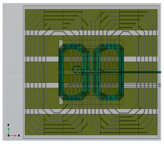
Figure 6.
Ferrite tiles arrangement in models A, B, C and S.
Self-inductance and coupling coefficient were tested on another model, named model S, as per recommendations from Standard SAE J2954 for WPT Level 3 in class Z1 [19]. The transmitter coil in the single DD topology has outer dimensions of 630 mm × 580 mm, with inner dimensions of 382 mm height and a minimum of 93 mm width. The receiver coil is also a single DD with outer dimensions 284 mm × 248 mm and inner dimensions 214 mm × 80 mm.
Inductive power transfer depends not only on the number of windings and their arrangement, but also on the ferrite shield, the purpose of which is to keep most of the magnetic field between the shields’ planes.
In simulations, ferrite tiles were arranged in two planes, each beside one of the coils. Tile arrangements and tile sizes were similar to those from the standard; the standard prescribes tile size of 90 mm × 100 mm, while the tiles used in conducted experiments are 100 mm × 100 mm, with a thickness of 6 mm and 12 mm. The tiles were arranged in parallel bands, with 3 to 7 tiles per one band.
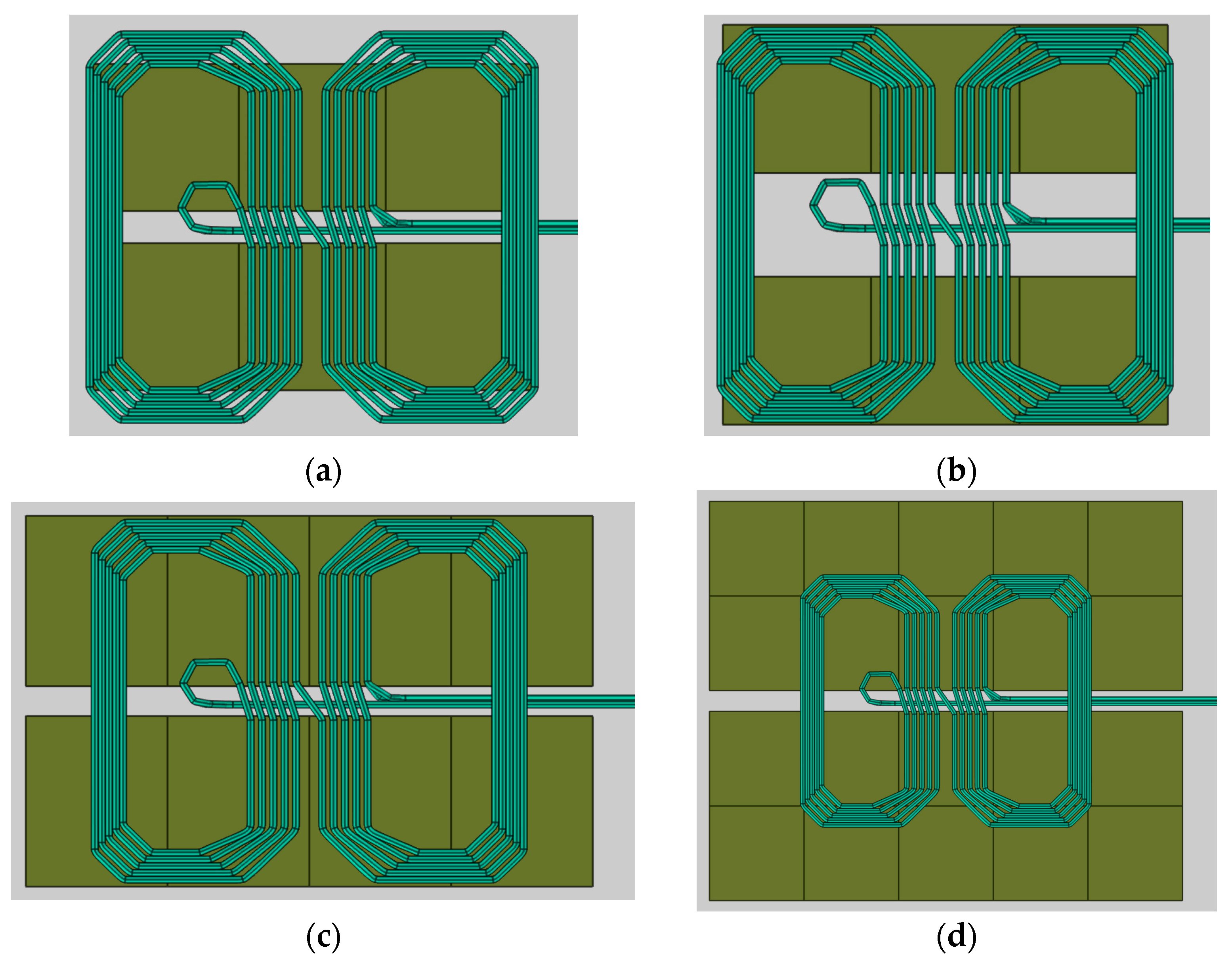
Simulation results showed that the length of one row of tiles should correspond to the size of the coil. Representative examples for the arrangement of ferrite tiles by the receiver and transmitter coil are shown in Figure 7 and Figure 8. Model configurations are shown in Table 2.

Figure 7.
Ferrite tile arrangement in the Rx part for (a) models 2, 3, 4, 7, 8, (b) model 5, (c) model 6, and (d) model 9.
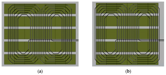
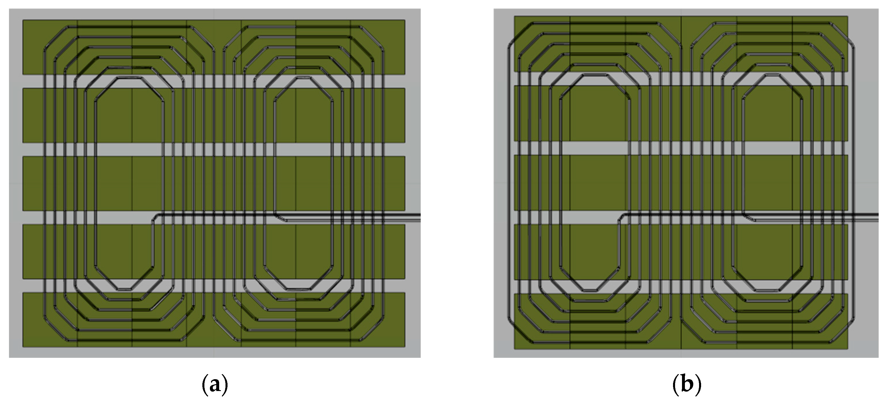
Figure 8.
Ferrite tile arrangement in the Tx part for (a) models 2, 3, 4, 5, 6, and (b) models 7, 8, 9.
Table 2.
Selected models with ferrite tile dimensions and arrangements.
Since inductive power transfer depends on the position of the transmitter assembly relative to the receiver assembly, the effect of the lateral displacement along the coil plane to the self-inductance and coupling coefficient was also investigated.
Modeling and simulations of conductor arrangement, ferrite patterns and Rx-Tx alignment were performed in COMSOL Multiphysics using 3D finite element method analysis. The magnetic field interface for AC currents was used, at the 85 kHz frequency.
Coils were modeled using the “Coil geometry analysis” node to determine the current direction for the “Numeric” coil type. Equations that cover this problem are based on Ampere’s law and magnetic vector formulations [44].
Ampere’s Law equation in magnetic vector potential formulation is given by:
where is permeability, specific conductivity, angular frequency, with the current density and the magnetic vector potential A as vectors in complex form [45].
The magnetic flux density B and the electric field strength E are related to the potentials in the following way:
In the magnetic quasi-static case, the electric field conservative component is equal to zero. Thus, the Equation (1) is solved for the magnetic vector potential only.
The self-inductances and , and the mutual inductance M are given by:
where , , are magnetic flux through coil 1, magnetic flux through coil 2, and magnetic flux through coil 2 due to magnetic field coil 1, respective. Coil currents are denoted with and . The magnetic flux emanating from coil 1 has two components: one component links only coil 1, and another component links both coils.
Coupling coefficient is the fraction of the magnetic flux produced by the current in one coil that links with the other coil:
The coil quality factor at the operating frequency ω is the quotient of the coil self-inductance and the coil resistance. The coil self-inductance and resistance depend on the coil geometry and materials it is made of:
2.1. Parameter Determination for the Equivalent Circuit with LCC and S Compensation Topology
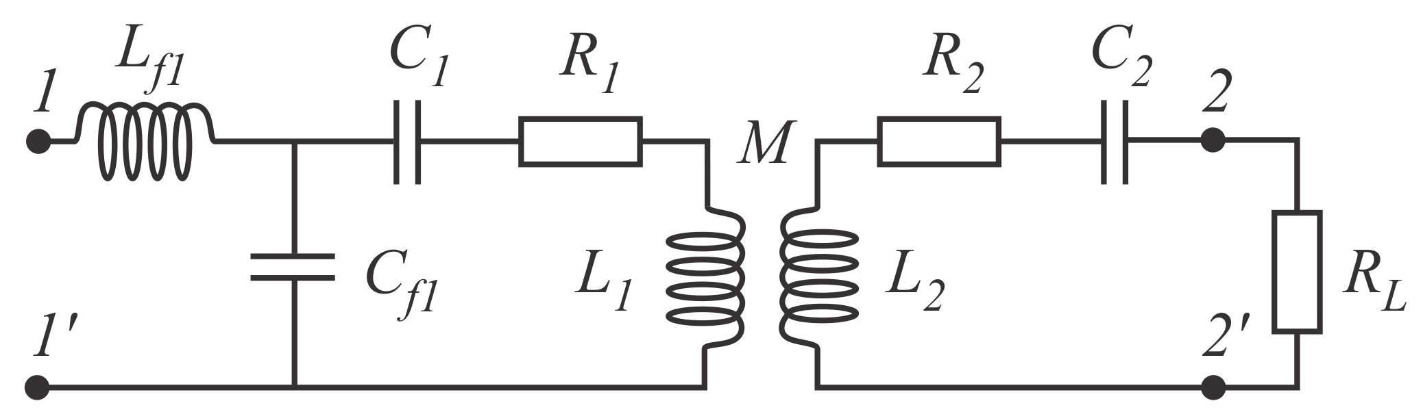
Simplified equivalent circuit (Figure 9), consists of two coupled inductors which represent the Tx and Rx coils, input voltage and resistive load. Additionally, due to the reactive power compensation, a inductor–capacitor–capacitor (LCC) on the primary side and a serial compensation capacitor (S) on secondary side were added to the circuit. A simple way to counteract inductive reactive power is to use capacitors to generate capacitive reactive power. Because of the low coupling coefficient k, to increase the power transfer, capacitors are added to compensate the reactive power from the inductors. The capacitors are marked with and in Figure 9. Serial compensation is often used in WPT applications.
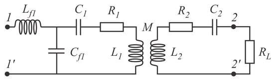
Figure 9.
Equivalent circuit for the WPT system with LCC and S compensation topology.
To adjust current intensity on the primary side, the pair , is added. LCC compensation consists of two capacitors, and , and an inductor . Internal coil resistances are denoted with and . Equivalent resistance of the load is connected between terminals 2 and 2′.
Battery voltage and desired transfer power are parameters set in advance, which determine the current in the secondary side of the circuit. LCC compensation on the primary side was chosen to compensate the reactive power and, at the same time, limit the current intensity at the input of the primary side. The procedure for determining the parameters for the LCC and S compensation circuit can be briefly described as follows:
Input impedance at the terminal pair 1-1′ is:
Ratio of voltages (between terminals 1 and 1′) and (between terminals 2 and 2′) is:
And the ratio of current intensities is:
From the expression (6) for the input impedance one obtains the required coil inductance :
The ratio of coil currents in (8) can be modified by varying the value of the inductance . From (7) the impedance can be approximated as . The value of is chosen as the function of the voltages at the input and output terminals ( and ), the output real power and the coupling coefficient k, which is dependent on M. As the current can have a large intensity, it must be limited according to the conductor wire cross section, at a maximum of 5 A/mm2.
Capacity is determined at resonance as:
Capacities and are determined at resonance as:
and
3. Numerical Simulation Results
Numerical simulations have shown that the system, shown in Figure 10 and Figure 11, is an adequate choice for a physical prototype. Coils were wound in two layers with two conductors each, according to Model A (Figure 3a). A magnetic shield made of ferrite tiles was positioned over the coils to increase the coupling factor, according to Model 7 (Figure 7a and Figure 8b). The magnetic shield also serves to reduce magnetic field leakage. At the transmitting side, 100 mm × 100 mm × 12 mm tiles were placed in five bands of six tiles each, with 25 mm spacing between the bands. Two bands of three 100 mm × 100 mm × 6 mm tiles were placed at the receiving side, also with 25 mm spacing between the bands.
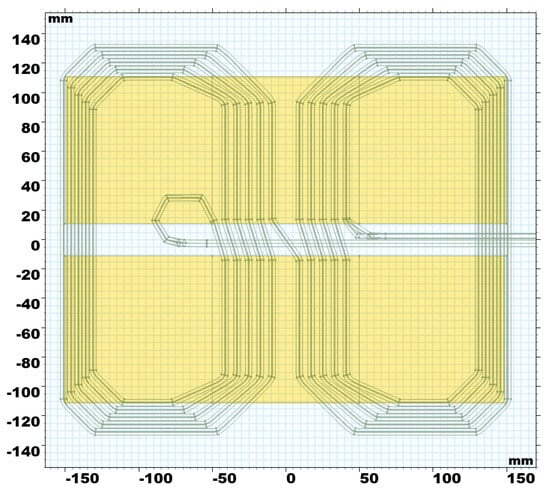
Figure 10.
Rx coil with ferrite tiles in the 2 × 3 pattern.
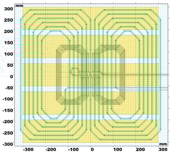
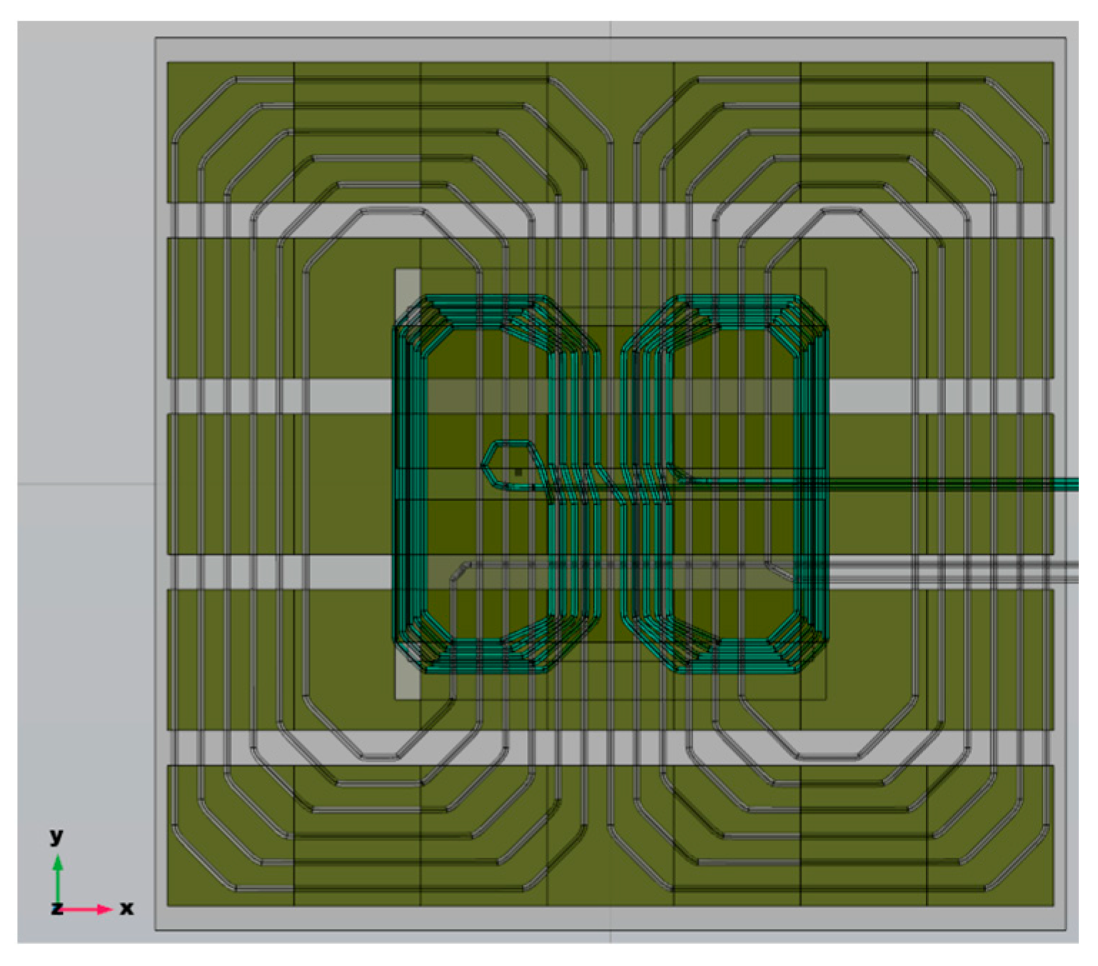
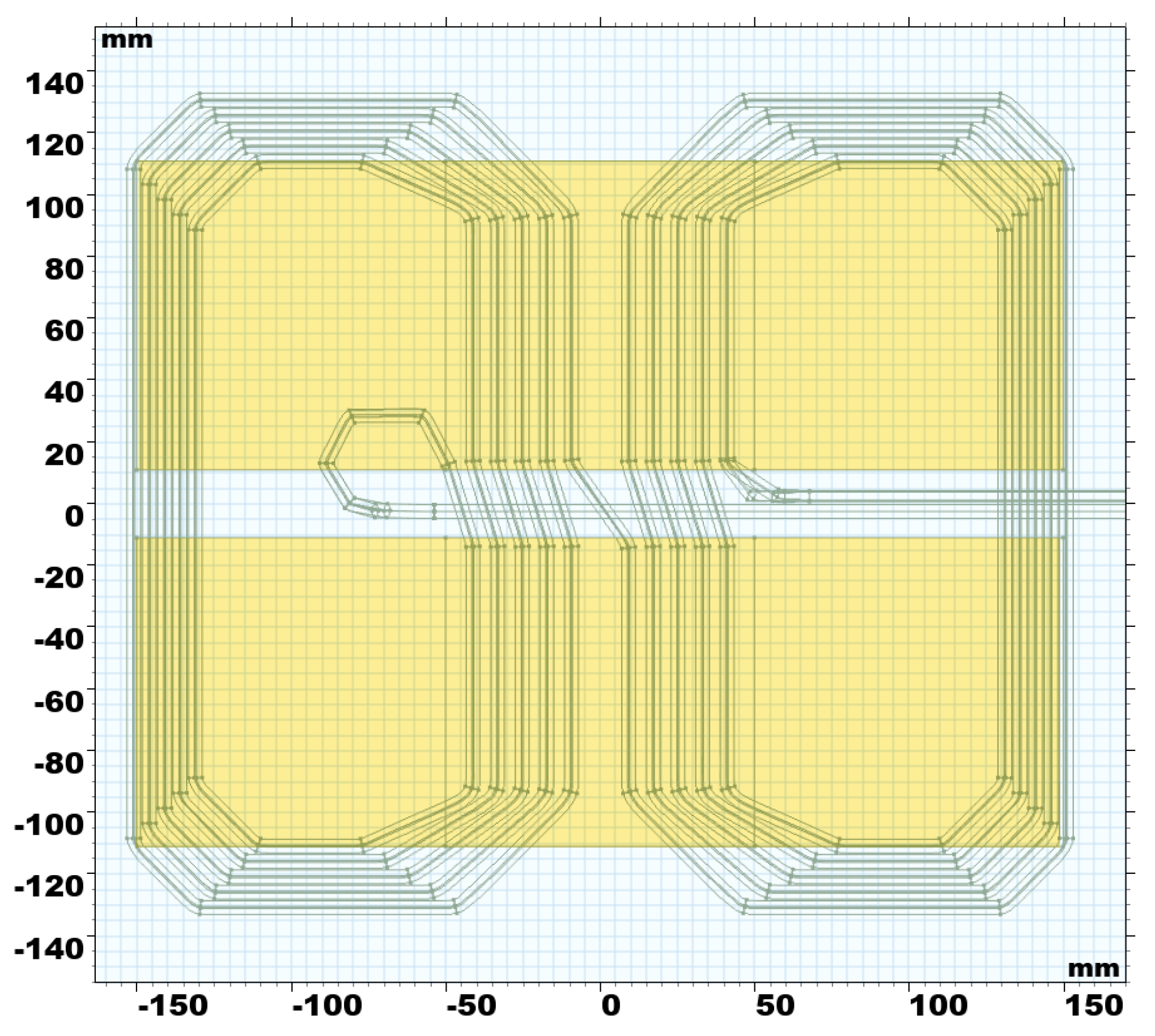
Figure 11.
Tx coil with ferrite tiles in the 5 × 6 pattern, overlaid with the Rx coil for comparison.
From (2), self-inductances of 60.5 μH for the transmitting coil and 26.1 μH for the receiving coil were calculated. The mutual inductance of 11.1 μH was calculated from (3) for a clearance distance of 100 mm at the 85 kHz frequency. Using the obtained values, the equivalent compensation circuit (LCC and S compensation) parameters were determined using the procedure described in Section 2.1. LCC-S compensation parameters are .
To examine the impact of tile thickness, another case was considered, where thinner and thicker tiles were switched around in the magnetic shield, while their layout remained the same. Thinner tiles (6 mm) were used in the transmitting assembly shield, and thicker ones (12 mm) in the receiving assembly shield. Values close to the first case were obtained, namely, self-inductance of 60.5 μH for the transmitting coil and 26.3 μH for the receiving coil. The mutual inductance was calculated at 10.9 μH. These results were expected because skin depth for ferrites at 85 kHz is around 3.5 mm. In other words, tile thickness had a negligible impact, and, for weight reduction purposes, only thinner tiles (6 mm thick) can be used.
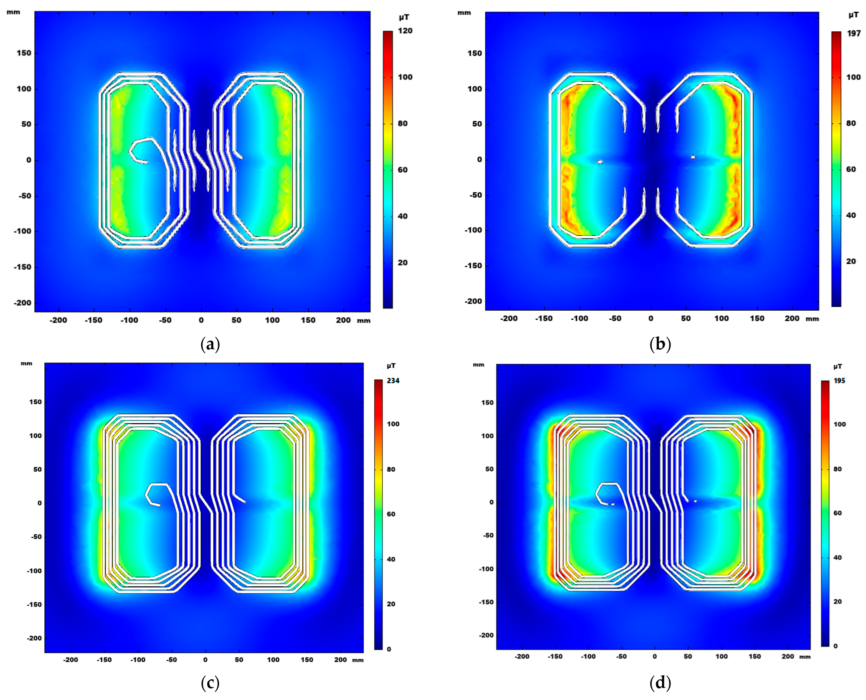
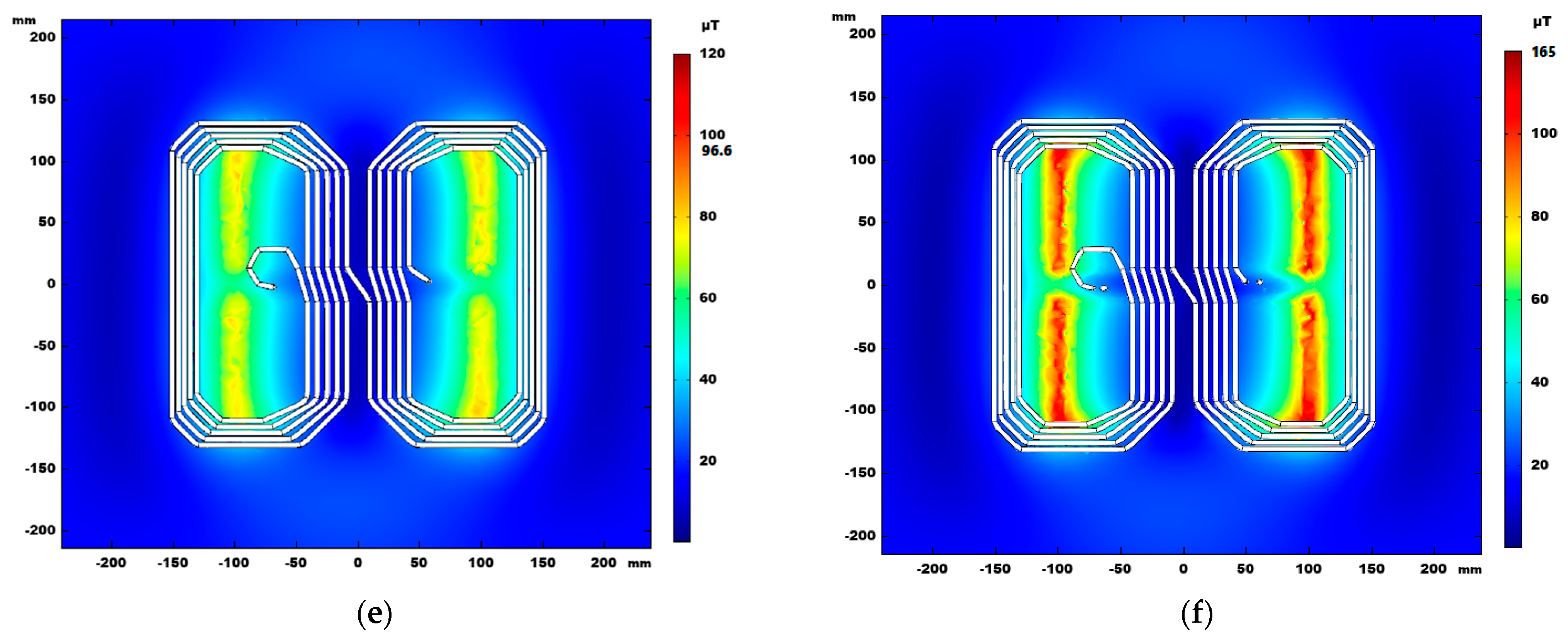
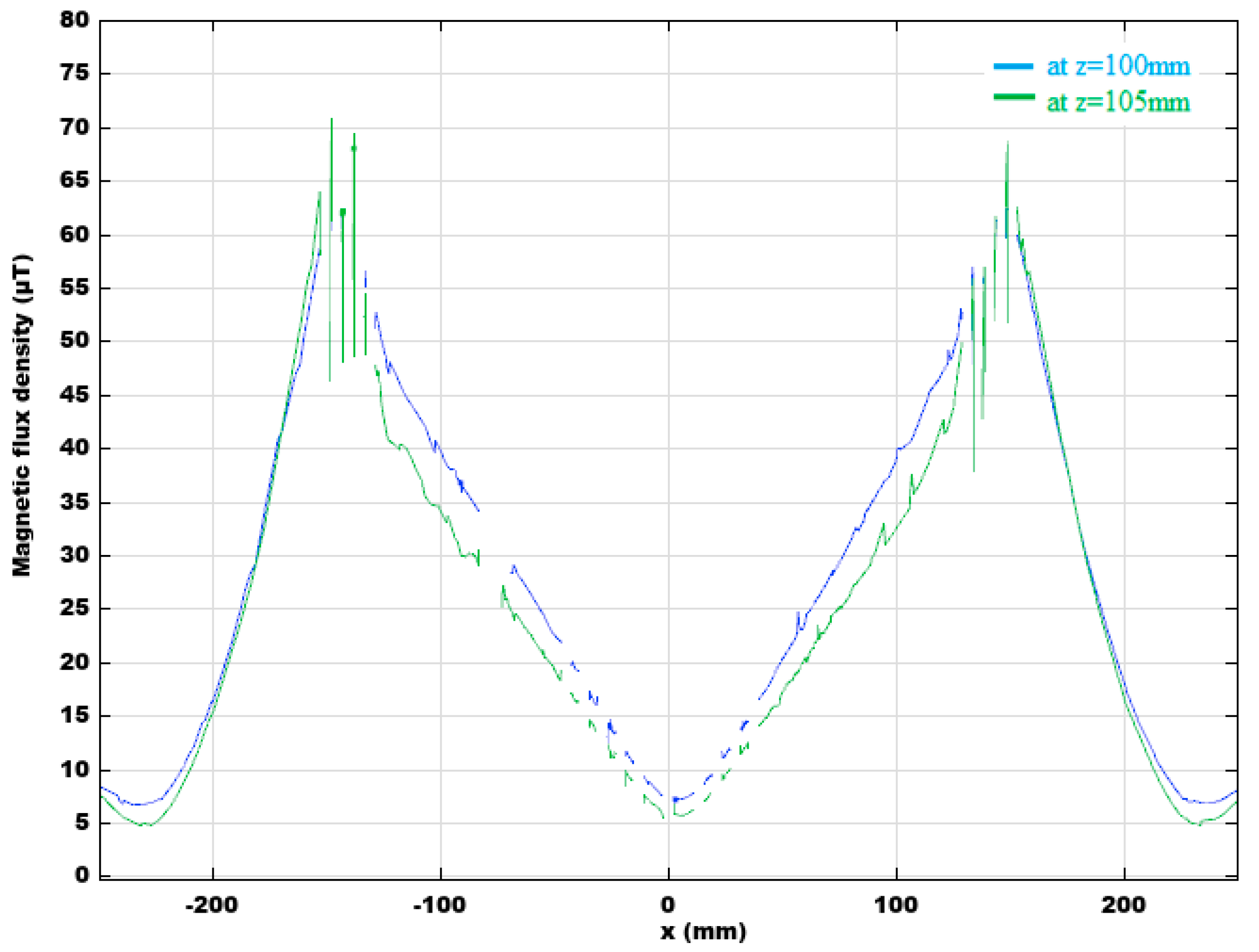
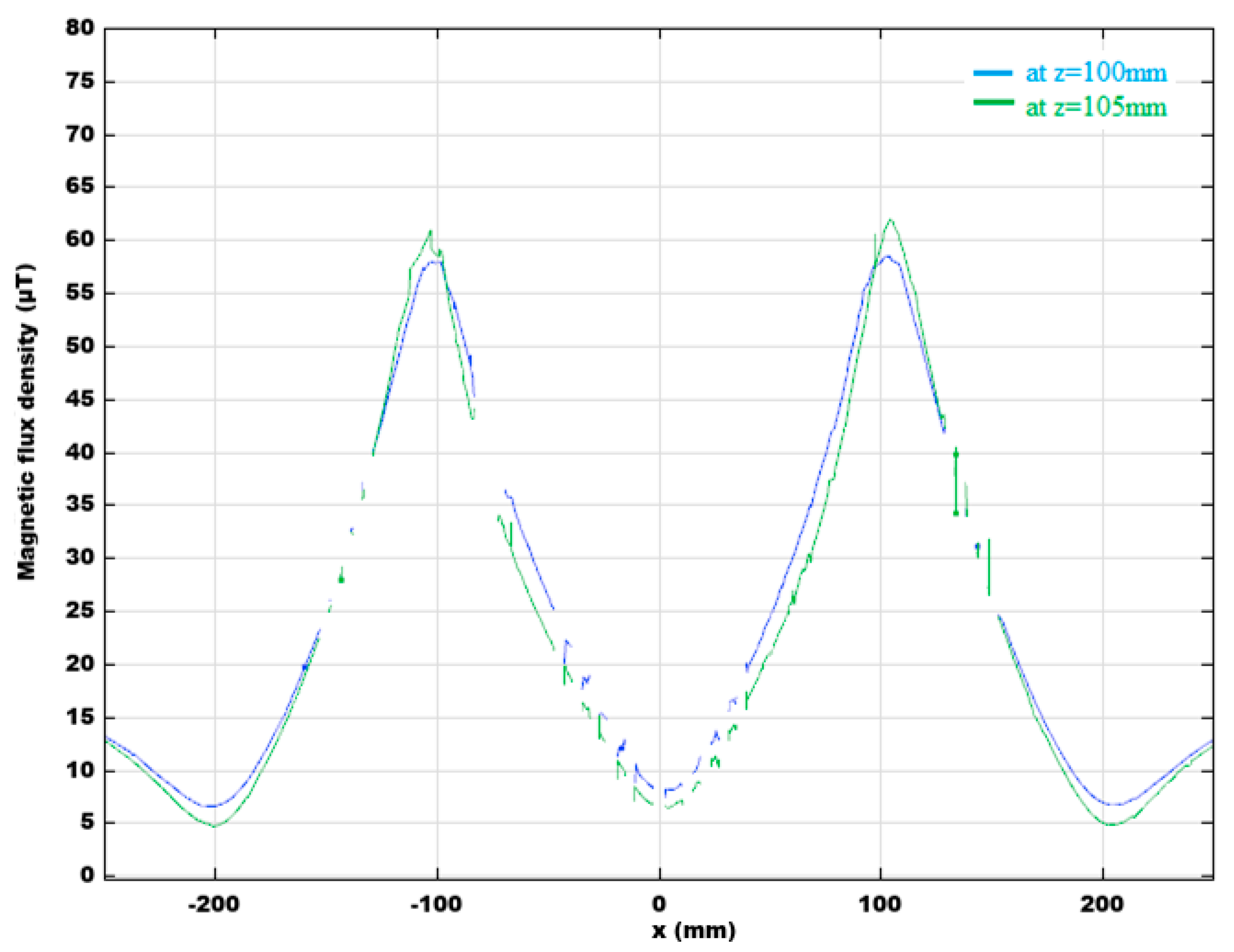
To determine the optimal size and layout of the magnetic shield, we consider magnetic flux density in the receiving assembly plane, at the first and second coil layers (Figure 12). The goal is to maximize the magnetic flux in the receiving assembly. Model A (Figure 3a) was examined in two shield configurations: the first, with two bands of three tiles (Figure 12c,d), and the second, with two bands of two tiles (Figure 12e,f). An excitation current of the same intensity was used in both cases. Spatial distribution of the magnetic flux density B, as well as maximum values, are easily identified. Obviously, the magnetic flux lines should be concentrated in the region occupied by the coils. Ferrite tiles outside of that region draw the magnetic field away from the coils and, as a result, reduce the magnetic flux. Similarly, the magnetic flux is reduced if the area covered by the tiles is smaller than the region occupied by the coils. These conclusions are supported by the results in Figure 13 and Figure 14, which show the intensity of B along the middle of the receiving coil, at both layers and for both considered cases. The surface below the curve is directly proportional to the magnetic flux along the centerline (Figure 15).
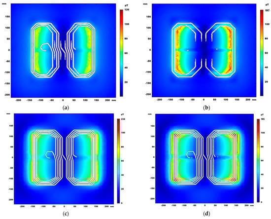
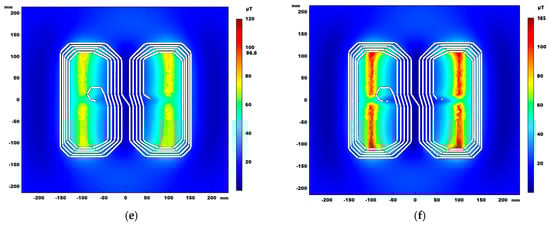
Figure 12.
Magnetic flux density in plane z = 100 mm (height of first layer Rx coil) and z = 105 mm (height of second layer Rx coil) for model S, model A case 1 (3 × 2 ferrite tiles 100 mm × 100 mm), model A case 2 (2 × 2 ferrite tiles 100 mm × 100 mm). (a) z = 100 mm, model S, (b) z = 105 mm, model S, (c) z = 100 mm, model A case 1, (d) z = 105 mm, model A case 1, (e) z = 100 mm, model A case 2, (f) z = 105 mm, model A case 2.
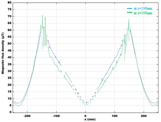
Figure 13.
Magnetic flux density for model A case 1 along the centerline, at the height z = 100 mm and z = 105 mm.
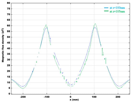
Figure 14.
Magnetic flux density for model A case 2 along the centerline, at the height z = 100 mm and z = 105 mm.
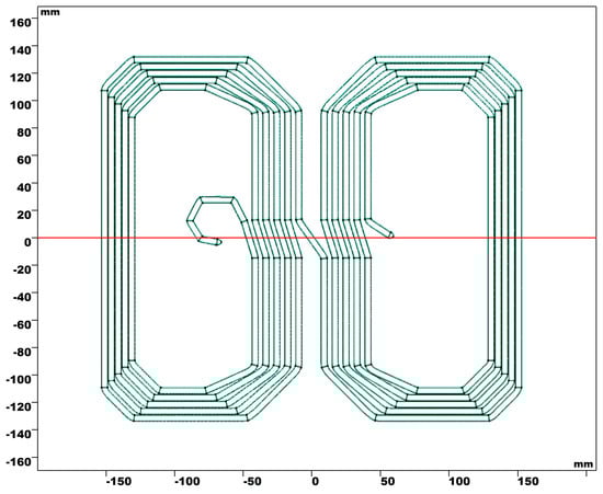
Figure 15.
Centerline (red) of the Rx coil.
Both curves in Figure 13 have larger values than curves in Figure 14, meaning that model A with 2 × 3 tiles yields a larger magnetic flux, as well as coupling coefficient, relative to model A with 2 × 2 tiles.
Simulations were also performed on model S, described in Section 2, which follows recommendations set by standard SAE J2954 for WPT Level 3 in class Z1. The distribution of magnetic flux density across receiving coil layers in model S is shown in Figure 12a,b.
The values of self-inductance, mutual inductance and coupling coefficient for models S, A and B are shown in Table 3. In the comparison between model S and both variants of model A, one concludes that model S has a lower value of the coupling coefficient. Numerical results show a somewhat improved coupling coefficient k over the reference design, obtained for the optimal ferrite layer layout. The improvement of approximately 13% is obtained for Model A case 1, k = 0.279 versus k = 0.245 for Model S.
Table 3.
Inductances obtained from simulations for models S, A and B.
3.1. Effect of the Arrangement and Number of Ferrite Tiles
Table 4 contains the results of coil self-inductance and mutual inductance calculations, using (2) and (3) in FEM simulations on models 1 through 9 from Table 2. Simulations were carried out in COMSOL Multiphysics Magnetic Fields interface in the frequency domain at the 85 kHz frequency.
Table 4.
Coil self-inductance and mutual inductance for models 1–9.
A summary of some aspects of magnetic layer design is given with respect to chosen models. The magnetic layer size and placement, distance between ferrite bands, tile thickness can be varied and optimized to maximize the magnetic coupling between the transmitting and receiving coil assemblies. Some characteristic cases are presented and discussed, which highlight the impact of each of the parameters on the performance of the considered WPT system.
Let us consider the impact of the magnetic layer size on the receiving coil. Comparing model 7 and model 9, with the increase in the surface of the ferrite layer at the receiving coil, the surface of the adjacent aluminum sheet covered by the ferrite also increases. In this way, induced currents are reduced in the covered portion of the aluminum sheet. Consequently, self-inductance of the transmitting coil increases (Table 4). Another consequence is that, due to the increase of the ferrite layer, the magnetic field in the transmitting coil is less dense in the central region, thus reducing the mutual inductance. From there, a conclusion can be drawn that the ferrite layer at the receiving coil should be as large as possible, but not larger than the receiving coil dimensions. The ferrite layer should also be centered to ensure that the magnetic flux density through the transmitter coil is maximized.
The effect of the ferrite layer gaps can be observed on the examples of models 4 and 5. While the two models have equal ferrite band surfaces, the distance between bands is larger in model 5, but the self-inductance of the receiver coil and the mutual inductance are lower. Although gaps are sometimes required to provide space for coil terminal wires, they should be reduced as much as possible.
Regarding the size of the ferrite layer at the transmitter coil, from the comparison between model 4 and model 7, the increase in the ferrite layer size brings a small increase in self-inductance of the transmitter coil, and a decrease in the mutual inductance.
The impact of tile thickness is clearly observable in a comparison between model 7 and model 8, where ferrite layers are of equal size, but with different thickness. In both cases, tile thickness is larger than the skin depth. The results in Table 4 illustrate that model 7 shows a slightly better performance, due to a larger mutual inductance. The coupling coefficient changes only slightly with ferrite thickness, as long as magnetic saturation is not reached. Based on calculations, simulation results and availability of ferrite tiles, the prototype was constructed based on model 7.
3.2. Misalignment Simulation Results for the Chosen Optimal Model
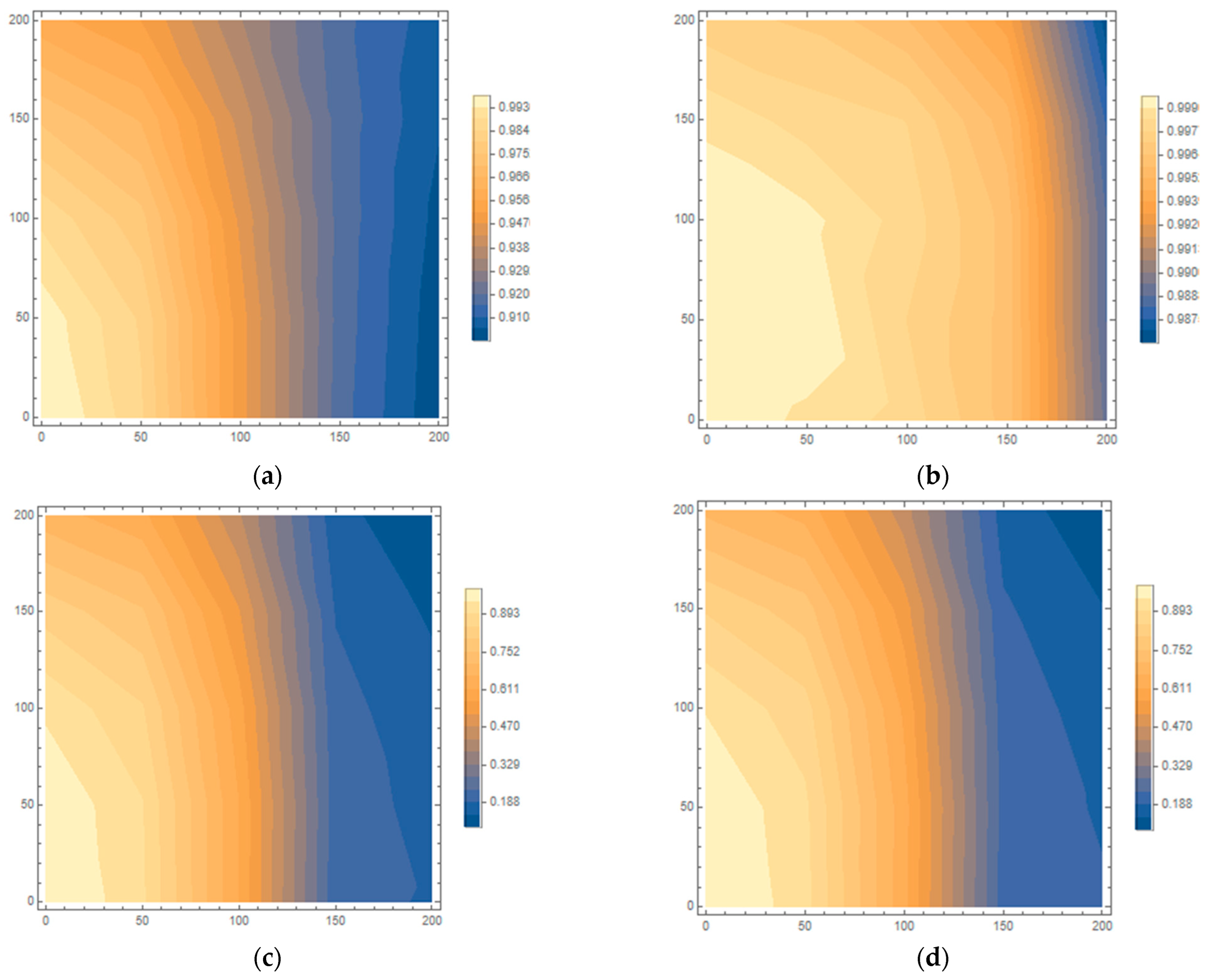
The effect of misalignment of inductive coupled coils on inductances and coupling coefficient was examined on Model 7. Lateral misalignment along the two axes perpendicular to the coil axes was considered, while the axes of the coils remained parallel to each other. The effect of rotation was not examined. Starting from perfectly aligned coils, the VA coil was displaced on the x-axis and y-axis directions from 0 to 200 mm. Although these misalignment values are too exaggerated relative to the size of the WPT system, they were nonetheless used in a series of simulations to better understand the resulting parameter variations. One characteristic subset of the results is shown in Figure 16.
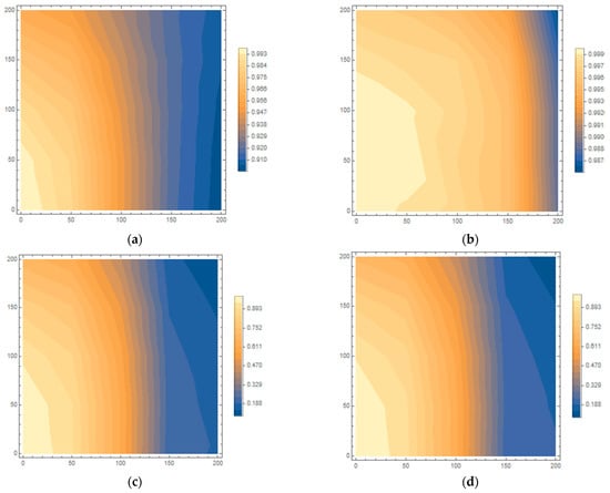
Figure 16.
Normalized change in (a) , (b) , (c) , (d) due to lateral displacement along the x and y axes.
4. Measurements
4.1. Physical Prototype Description
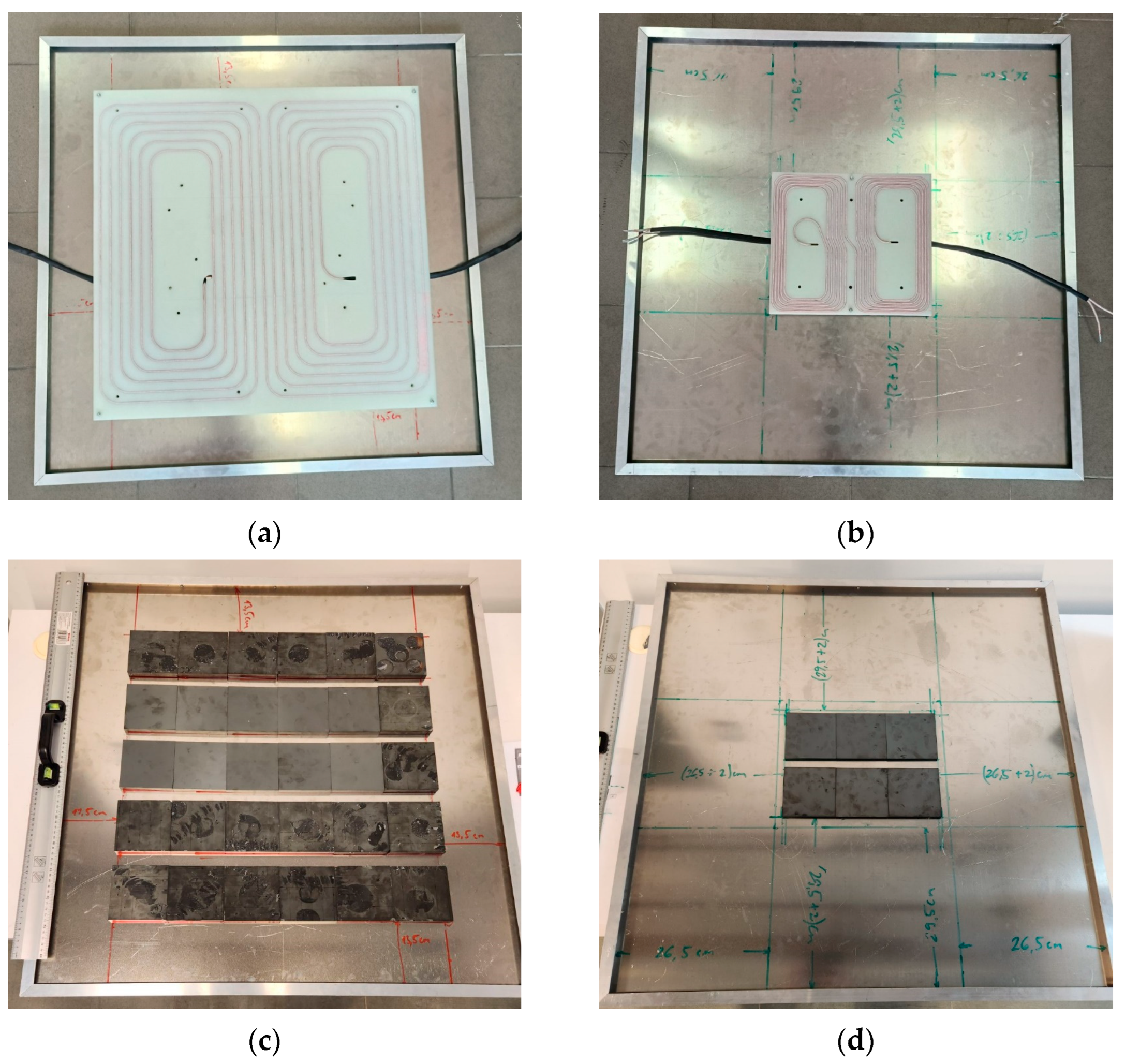
The components of inductive power pads for the WPT system, Tx and Rx coils, ferrite tile and aluminum plate shields are shown in Figure 17. Slits for wires were milled in the acrylic trays, hence those wires could be placed in two layers. The outer (deeper) layer was wound first, and then, the inner layer was wound on top of it. Finally, both wires were connected in parallel. The ferrite tiles were affixed between the acrylic and aluminum sheets. The size and arrangement of coils and ferrite tiles correspond to the specification of the optimal model (model 7) based on the simulations shown in Table 5.
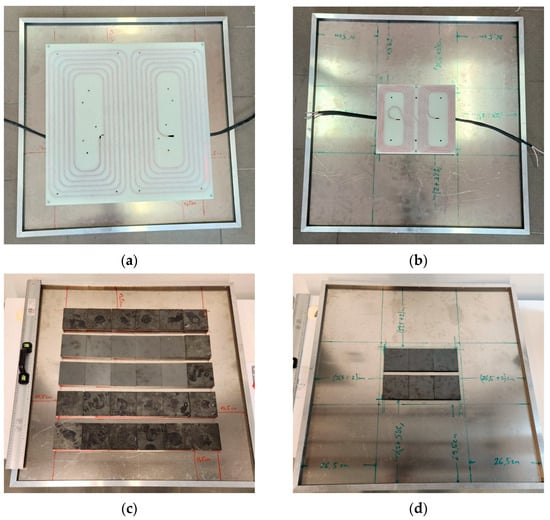
Figure 17.
Coil and ferrite arrangements: (a,c) Transmitting pad, (b,d) Receiving pad.
Table 5.
WPT system parameters.
An inductive power pad consists of a wire tray with two layers of wire windings, ferrite tiles and aluminum plate shield. One pad is in the transmitting assembly, and the other is in the receiving assembly. The pads are centered and placed so that the coils are facing each other. Plastic spacers are placed between the pads to ensure that coils are at the desired distance.
4.2. Experimental Verification
The self-inductance and mutual inductance were measured for the transmitting and receiving pads shown in Figure 18, with the coils exactly 100 mm apart. Before the measurements, both pads must be placed together, as it described, to ensure that the effects of magnetic fields generated by currents induced in the aluminum shield are considered in measurement results.
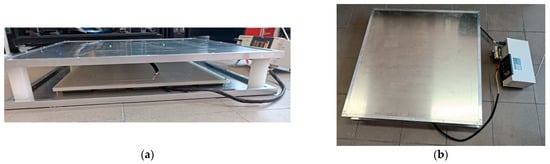
Figure 18.
Tx and Rx pads, (a) side view and (b) top view.
The measurements were performed using Hioki LCR Meters and Impedance Analyzers IM3590 [46]. All measurements were performed at the nominal frequency of 85 kHz and the frequency range from 79 kHz to 100 kHz. The experimental and measurement results are shown in Table 6.
Table 6.
Comparison of experimental and simulated parameters on model 7.
The values of parameters , , and are calculated using Equations (6)–(9) as well as the values of coil self-inductances and the mutual inductance. Therefore, numerical results must be confirmed by experimental measurements beforehand. Thus, the FE model is validated.
When designing the actual circuit with LCC and S compensation, available capacitors and inductors with values closest to the calculated values are used. The electrical circuit can be fine-tuned afterwards by adjusting the inverter switching frequency (Table 7) to the desired one.
Table 7.
System parameters of the WPT system.
4.3. Experimental WPT System
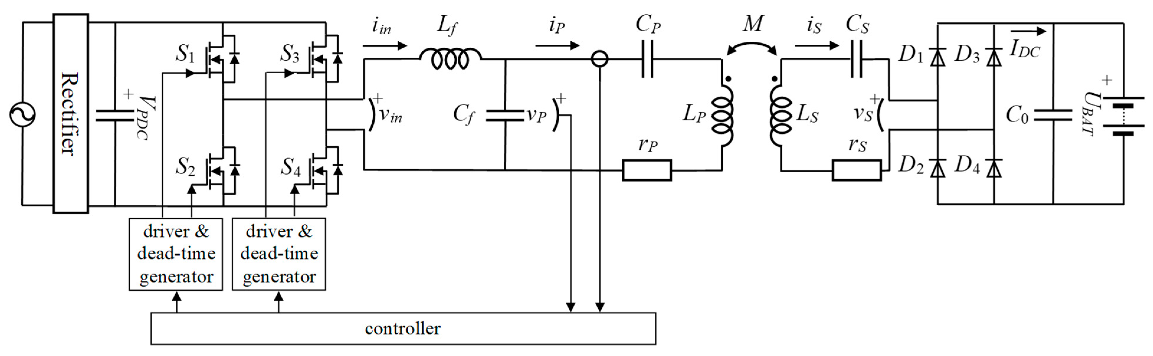
The constructed experimental WPT system is represented by the equivalent electric circuit shown in Figure 19. Values of circuit components are provided in Table 7.
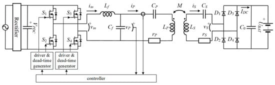
Figure 19.
Electric circuit diagram of LCC-S compensated WPT system.
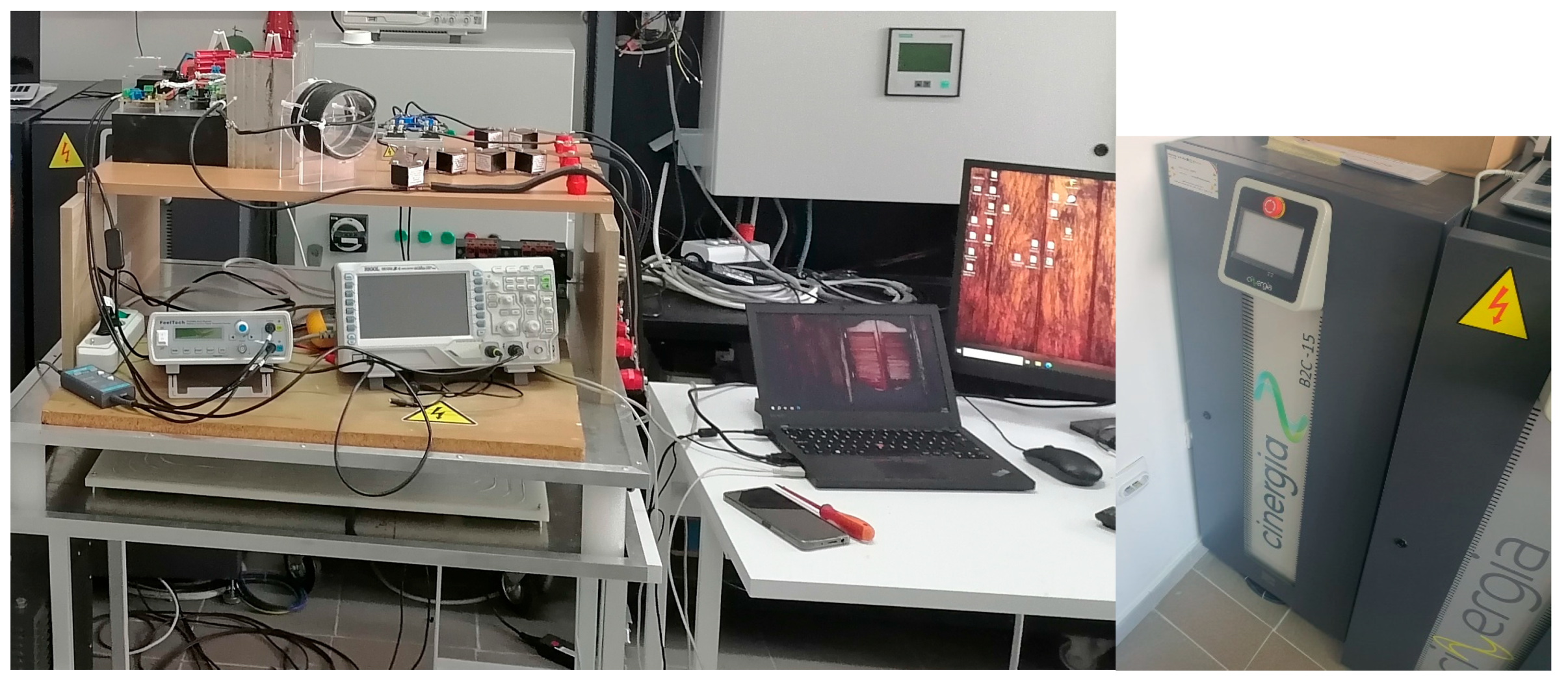
The system is supplied from a standard three-phase grid network at 3 × 400 VAC, which provides 560 VDC input DC voltage for the inverter. The inverter consists of four SiC MOSFETs G3R20MT12N (S1-S4), forming the full bridge configuration. The switching frequency of the inverter is in the standard frequency range of 79–90 kHz with the control resolution of 10 Hz. To control output voltage and thus transferred power, phase shift control of the inverter is realized. The resolution of the phase control is 0.10. The evaluation board series EVAL-1ED3491MX12M with MOSFET desaturation protection is used for MOSFET control. The switching dead-time is set to 300 ns. The capacitors used for , and are from MULTICOMP MP00409x series. The secondary side rectifier consists of four fast recovery diodes DSEI2 × 101-06A with forward voltage drop of 1.25 V. The battery with the nominal capacity of 100 Ah is simulated using CINERGIA B2C + battery simulator, which allows maximum load power up to 15 kW and voltage up to 700 VDC. The algorithm for controlling the WPT system depicted in Figure 19 is realized using MATLAB scripts. The acquisition of measured data of the primary side voltage and current is performed using a RIGOL DS1202Z-E oscilloscope. The current oscilloscope probe used for measurement is MICSIG CP2100B. The switching frequency, phase angle and PWM signals are generated by function generator FeelTech FY3200S. The experimental setup is shown in Figure 20.
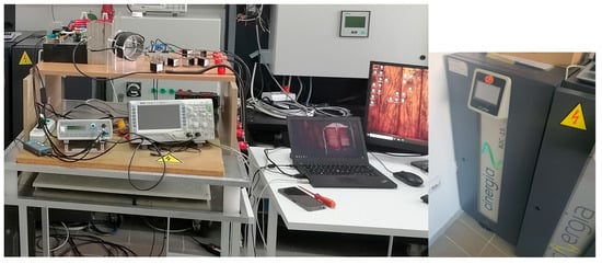
Figure 20.
The WPT system in a measuring setup.
Tuning the phase angle of the inverter operation to 140° during the experimental measurement, a transferred power of 11 kW was achieved, with a 93% DC-DC efficiency. Efficiency is the ratio between output side DC power and inverter input side DC power. The battery equivalent resistance is 20 Ω, while equivalent resistance of the rectifier and battery, neglecting parasitic inductances, seen by AC side is 16.2 Ω.
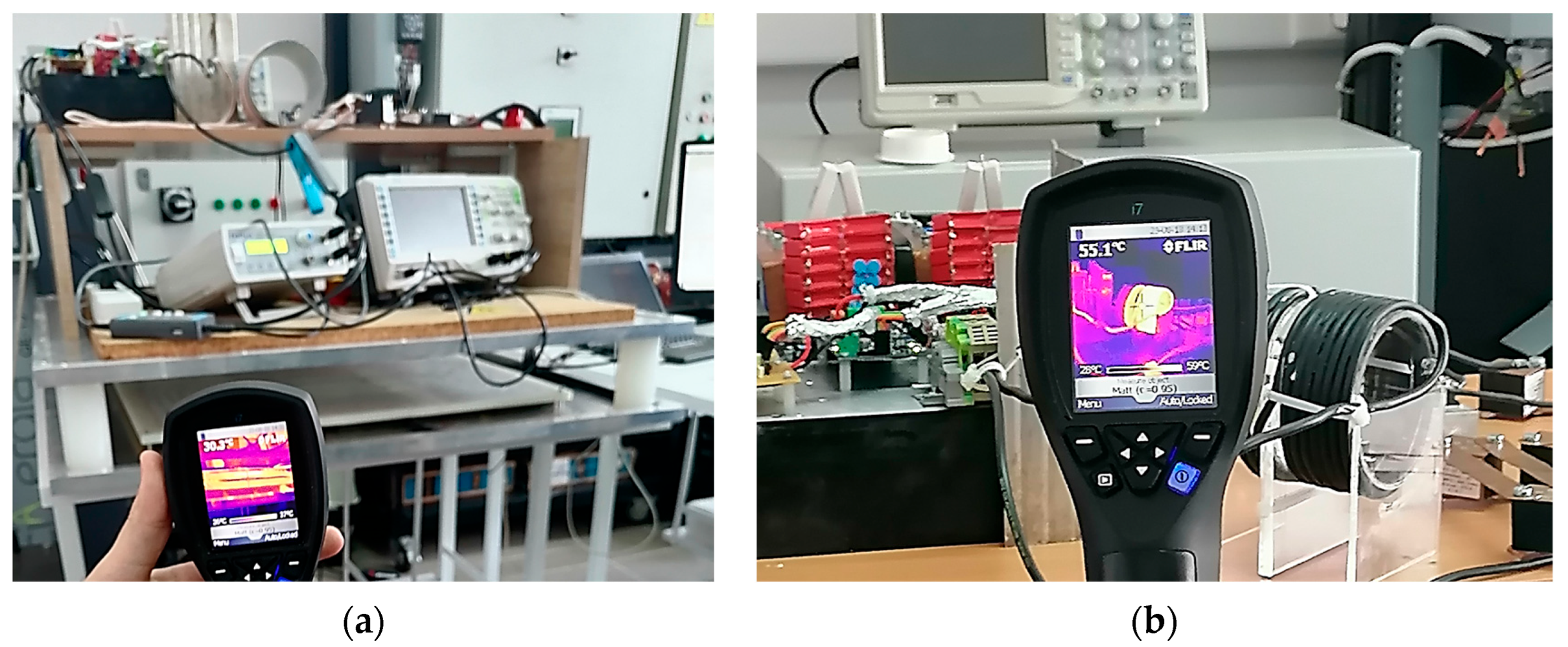
In laboratory testing, the temperature of the system was monitored with a thermal camera, Figure 21. At the 11 kW power, the Tx and Rx coil temperatures rose slightly above the room temperature, while the highest temperatures, 55 °C, were observed at the LCC compensation coil.

Figure 21.
Temperature monitoring with a thermal camera in laboratory tests for (a) the Tx and Rx coil and (b) the LCC compensation inductor.
4.4. Future Work
With the rise of electric vehicles that require more power, such as heavy-duty trucks and buses, and the development of new battery chemistries beyond lithium-ion technology, research into efficient and rapid charging methods at power levels several times higher than 11 kW is becoming a major focus. One potential research direction is the improvement of power transfer by utilizing multi-coil systems.
5. Conclusions
As electric vehicles become more prevalent, the requirements for charging power and efficiency are increasing. In this paper the coil design for a wireless power transfer system is described, which was constructed in accordance with requirements for the contactless electric vehicle charging system. The design requirements mandated a successful transfer at 11 kW, while maintaining the dimensions of the system within reasonable limits for the implementation in electric vehicles. The impact of coil geometry, ferrite tile arrangement and misalignment tolerance were investigated in numerical simulations using the finite element model. The performance of the proposed design was compared with the performance of single-layer coils given by Standard SAE J2954 for WPT Level 3 in class Z1. The numerical results indicate an improved coupling coefficient k over the reference design, obtained for the optimal ferrite layer layout. In the best case (Model A case 1) an improvement of approximately 13% was achieved with k = 0.279 versus k = 0.245 for the single layer coil.
Based on the simulations, one coil design and a ferrite arrangement that performed best were identified. Then, the proposed setup and adequate LCC and S compensation topology were implemented. The proposed design was validated through laboratory testing for the 11 kW power transfer, which achieved 93% DC-DC efficiency.
Author Contributions
Conceptualization, D.H. and V.T.; methodology, D.H., V.R., Ž.D. and P.O.; software, D.H.; validation, Z.K., P.O. and Z.V.; formal analysis, D.H., V.R. and Ž.D.; investigation, D.H., V.R., Ž.D., B.P. and M.Š.; resources, V.T. and M.Š.; data curation, V.T.; writing—original draft preparation, D.H.; writing—review and editing, V.T. and V.R.; visualization, D.H., Ž.D. and B.P.; supervision, I.F. and P.O.; project administration, Z.V., K.W. and Z.K. All authors have read and agreed to the published version of the manuscript.
Funding
This research was funded by projects 2020-1.1.2-PIACI-KFI-2020-00166 and 2020-1.1.2-PIACI-KFI-2020-00173 of the University of Dunaujvaros and by project GINOP_PLUSZ-2.1.1-21-2022-00249 of the Óbuda University, co-financed by the Hungarian State.
Data Availability Statement
Data are contained within the article.
Acknowledgments
The authors would like to thank the editors and the anonymous reviewers for their valuable comments that significantly improved the quality of this paper.
Conflicts of Interest
The authors declare no conflicts of interest.
References
- Bosshard, R.; Kolar, J.W. Multi-Objective Optimization of 50 kW/85 kHz IPT System for Public Transport. IEEE J. Emerg. Sel. Top. Power Electron. 2016, 4, 1370–1382. [Google Scholar] [CrossRef]
- Ahmad, A.; Alam, M.S.; Chabaan, R. A comprehensive review of wireless charging technologies for electric vehicles. IEEE Trans. Transp. Electrif. 2018, 4, 38–63. [Google Scholar] [CrossRef]
- Dai, J.; Ludois, D.C. A Survey of Wireless Power Transfer and a Critical Comparison of Inductive and Capacitive Coupling for Small Gap Applications. IEEE Trans. Power Electron. 2015, 30, 6017–6029. [Google Scholar] [CrossRef]
- Sasaki, S.; Tanaka, K.; Maki, K. Microwave Power Transmission Technologies for Solar Power Satellites. Proc. IEEE 2013, 101, 1438–1447. [Google Scholar] [CrossRef]
- Mayordomo, I.; Dräger, T.; Spies, P.; Bernhard, J.; Pflaum, A. An Overview of Technical Challenges and Advances of Inductive Wireless Power Transmission. Proc. IEEE 2013, 101, 1302–1311. [Google Scholar] [CrossRef]
- Park, Y.-J. Next-generation wireless charging systems for mobile devices. Energies 2022, 15, 3119. [Google Scholar] [CrossRef]
- Van, S.D.; Ngo, H.Q.; Cotton, S.L. Wireless powered wearables using distributed massive mimo. IEEE Trans. Commun. 2020, 68, 2156–2172. [Google Scholar] [CrossRef]
- Campi, T.; Cruciani, S.; Palandrani, F.; De Santis, V.; Hirata, A.; Feliziani, M. Wireless Power Transfer charging system for AIMDs and pacemakers. IEEE Trans. Microw. Theory Technol. 2016, 64, 633–642. [Google Scholar] [CrossRef]
- Wang, G.; Liu, W.; Sivaprakasam, M.; Kendir, G.A. Design and analysis of an adaptive transcutaneous power telemetry for biomedical implants. IEEE Trans. Circuits Syst. I Regul. Pap. 2005, 52, 2109–2117. [Google Scholar] [CrossRef]
- Fadhel, Y.B.; Bouattour, G.; Bouchaala, D.; Derbel, N.; Kanoun, O. Model-Based Optimization of Spiral Coils for Improving Wireless Power Transfer. Energies 2023, 16, 6886. [Google Scholar] [CrossRef]
- Sezer, C.; Altintas, N. Adaptation of Inductive Power Transfer to Small Household Appliances That Can Operate on Induction Heating Cooktops: Wireless Electric Kettle. Energies 2023, 16, 3544. [Google Scholar] [CrossRef]
- Aziz, A.F.A.; Romlie, M.F.; Baharudin, Z. Review of inductively coupled power transfer for electric vehicle charging. IET Power Electron. 2019, 12, 3611–3623. [Google Scholar] [CrossRef]
- Trivino, A.; Gonzalez-Gonzalez, J.M.; Aguado, J.A. Wireless power transfer technologies applied to electric vehicles: A review. Energies 2021, 14, 1547. [Google Scholar] [CrossRef]
- Mohamed, A.A.S.; Shaier, A.A.; Metwally, H.; Selem, S.I. An overview of dynamic inductive charging for electric vehicles. Energies 2022, 15, 5613. [Google Scholar] [CrossRef]
- Chittoor, P.K.; Chokkalingam, B.; Mihet-Popa, L. A review on UAV wireless charging: Fundamentals, applications, charging techniques and standards. IEEE Access 2021, 9, 69235–69266. [Google Scholar] [CrossRef]
- Kim, J.; Kim, K.; Kim, H.; Kim, D.; Park, J.; Ahn, S. An efficient modeling for underwater wireless power transfer using z-parameters. IEEE Trans. Electromagn. Compat. 2019, 61, 2006–2014. [Google Scholar] [CrossRef]
- Campi, T.; Cruciani, S.; Feliziani, M. Wireless Power Transfer Technology Applied to an Autonomous Electric UAV with a Small Secondary Coil. Energies 2018, 11, 352. [Google Scholar] [CrossRef]
- Zhang, S.; Yu, J.J.Q. Electric vehicle dynamic wireless charging system: Optimal placement and vehicle-to-grid scheduling. IEEE Internet Things J. 2022, 9, 6047–6057. [Google Scholar] [CrossRef]
- SAE J2954; Wireless Power Transfer for Light-Duty Plug-In/Electric Vehicles and Alignment Methodology. SAE International: Pittsburgh, PA, USA, 2019.
- SAE J2954/2; Wireless Power Transfer for Heavy-Duty Electric Vehicles. SAE International: Pittsburgh, PA, USA, 2022.
- IEC 61980; Electric Vehicle Wireless Power Transfer (wpt) Systems—Part 1: General Requirements. International Electrotechnical Commission: Geneva, Switzerland, 2016.
- Sulejmani, E.; Beltle, M.; Tenbohlen, S. EMC of Inductive Automotive Charging Systems According to Standard SAE J2954. Vehicles 2023, 5, 1532–1552. [Google Scholar] [CrossRef]
- Feng, H.; Tavakoli, R.; Onar, O.C.; Pantic, Z. Advances in High-Power Wireless Charging Systems: Overview and Design Considerations. IEEE Trans. Transp. Electrif. 2020, 6, 886–919. [Google Scholar] [CrossRef]
- Patil, D.; McDonough, M.K.; Miller, J.M.; Fahimi, B.; Balsara, P.T. Wireless Power Transfer for Vehicular Applications: Overview and Challenges. IEEE Trans. Transp. Electrif. 2018, 4, 3–37. [Google Scholar] [CrossRef]
- Bandyopadhyay, S.; Venugopal, P.; Dong, J.; Bauer, P. Comparison of Magnetic Couplers for IPT Based EV Charging Using Multi-Objective Optimization. IEEE Trans. Veh. Technol. 2019, 68, 5416–5429. [Google Scholar] [CrossRef]
- Liu, N.; Habetler, T.G. Design of a Universal Inductive Charger for Multiple Electric Vehicle Models. IEEE Trans. Power Electron. 2015, 30, 6378–6390. [Google Scholar] [CrossRef]
- Bosshard, R.; Mühlethaler, J.; Kolar, J.W.; Stevanović, I. Optimized magnetic design for inductive power transfer coils. In Proceedings of the 2013 Twenty-Eighth Annual IEEE Applied Power Electronics Conference and Exposition (APEC), Long Beach, CA, USA, 17–21 March 2013; pp. 1812–1819. [Google Scholar] [CrossRef]
- Khalid, H.; Mekhilef, S.; Mubin, M.; Seyedmahmoudian, M. Advancements in inductive power transfer: Overcoming challenges and enhancements for static and dynamic electric vehicle applications. Energy Rep. 2023, 10, 3427–3452. [Google Scholar] [CrossRef]
- Elnail, K.E.I.; Huang, X.; Xiao, C.; Tan, L.; Haozhe, X. Core Structure and Electromagnetic Field Evaluation in WPT Systems for Charging Electric Vehicles. Energies 2018, 11, 1734. [Google Scholar] [CrossRef]
- Zaheer, A.; Kacprzak, D.; Covic, G.A. A bipolar receiver pad in a lumped IPT system for electric vehicle charging applications. In Proceedings of the 2012 IEEE Energy Conversion Congress and Exposition (ECCE), Raleigh, NC, USA, 15–20 September 2012; p. 283. [Google Scholar] [CrossRef]
- Thein, M.E.; Charoensuk, J.; Masomtob, M.; Onreabroy, W.; Kaewpradap, A. Investigation of power transfer efficiency: Utilizing different coil designs in wireless charging of electric vehicles. In Proceedings of the 11th TSME-International Conference on Mechanical Engineering (TSME-ICoME 2020), Ubon Ratchathani, Thailand, 1–4 December 2020. [Google Scholar] [CrossRef]
- Yang, Y.; Cui, J.; Cui, X. Design and Analysis of Magnetic Coils for Optimizing the Coupling Coefficient in an Electric Vehicle Wireless Power Transfer System. Energies 2020, 13, 4143. [Google Scholar] [CrossRef]
- González-González, J.M.; Triviño-Cabrera, A.; Aguado, J.A. Assessment of the Power Losses in a SAE J2954—Compliant Wireless Charger. IEEE Access 2022, 10, 54474–54483. [Google Scholar] [CrossRef]
- Song, K.; Lan, Y.; Zhang, X.; Jiang, J.; Sun, C.; Yang, G.; Yang, F.; Lan, H. A Review on Interoperability of Wireless Charging Systems for Electric Vehicles. Energies 2023, 16, 1653. [Google Scholar] [CrossRef]
- Okasili, I.; Elkhateb, A.; Littler, T. A Review of Wireless Power Transfer Systems for Electric Vehicle Battery Charging with a Focus on Inductive Coupling. Electronics 2022, 11, 1355. [Google Scholar] [CrossRef]
- Despotović, Ž.; Reljić, D.; Vasić, V.; Oros, D. Steady-state multiple parameters estimation of the inductive power transfer system. IEEE Access 2022, 10, 46878–46894. [Google Scholar] [CrossRef]
- Ali, E.M.; Alibakhshikenari, M.; Virdee, B.S.; Soruri, M.; Limiti, E. Efficient Wireless Power Transfer via Magnetic Resonance Coupling Using Automated Impedance Matching Circuit. Electronics 2021, 10, 2779. [Google Scholar] [CrossRef]
- Li, W.; Zhao, H.; Deng, J.; Li, S.; Mi, C.C. Comparison Study on SS and Double-Sided LCC Compensation Topologies for EV/PHEV Wireless Chargers. IEEE Trans. Veh. Technol. 2016, 65, 4429–4439. [Google Scholar] [CrossRef]
- Chen, Y.; Zhang, H.; Shin, C.S.; Seo, K.H.; Park, S.J.; Kim, D.H. A Comparative Study of S-S and LCC-S Compensation Topology of Inductive Power Transfer Systems for EV Chargers. In Proceedings of the 2019 IEEE 10th International Symposium on Power Electronics for Distributed Generation Systems (PEDG), Xi’an, China, 3–6 June 2019. [Google Scholar] [CrossRef]
- Li, Y.; Zhu, Y.; Liu, W.; Zhu, Y.; Pei, Y.; Wen, H.; Zhao, C. High Efficiency WPT System for Electric Vehicles with LCL-S and SS compensation. In Proceedings of the IEEE 4th International Future Energy Electronics Conference (IFEEC), Singapore, 25–28 November 2019. [Google Scholar] [CrossRef]
- Zhu, Y.; Wu, H.; Li, F.; Zhu, Y.; Pei, Y.; Liu, W. A Comparative Analysis of S-S and LCCL-S Compensation for Wireless Power Transfer with a Wide Range Load Variation. Electronics 2022, 11, 420. [Google Scholar] [CrossRef]
- Chen, Y.; Zhang, H.; Park, S.J.; Kim, D.H. A Switching Hybrid LCC-S Compensation Topology for Constant Current/Voltage EV Wireless Charging. IEEE Access 2019, 7, 133924–133935. [Google Scholar] [CrossRef]
- Herceg, D.; Juhas, A.; Milutinov, M. A Design of a Four Square Coil System for a Biomagnetic Experiment. Facta Univ. Ser. Electron. Energ. 2009, 22, 285–292. [Google Scholar] [CrossRef]
- COMSOL Multiphysics Software. Available online: http://www.comsol.com (accessed on 2 November 2023).
- Popović, B. Elektromagnetika, 6th ed.; IP Nauka: Belgrade, Serbia, 2001; pp. 233–272. [Google Scholar]
- Hioki—LCR Meters, Impedance Analyzers, Capacitance Meters. Available online: https://www.hioki.com/ (accessed on 5 November 2023).


Disclaimer/Publisher’s Note: The statements, opinions and data contained in all publications are solely those of the individual author(s) and contributor(s) and not of MDPI and/or the editor(s). MDPI and/or the editor(s) disclaim responsibility for any injury to people or property resulting from any ideas, methods, instructions or products referred to in the content. |
© 2024 by the authors. Licensee MDPI, Basel, Switzerland. This article is an open access article distributed under the terms and conditions of the Creative Commons Attribution (CC BY) license (https://creativecommons.org/licenses/by/4.0/).