Article

Performance Analysis of Reconnaissance Coverage for HUAV Swarms under Communication Interference Based on Different Architectures

by
Yongjian Fan
1,
Bing Chen
1,2,*,
Yunlong Zhao
1,
Feng Hu
1,
Chunyan Liu
1 and
Yang Li
3
1
College of Computer Science and Technology, Nanjing University of Aeronautics and Astronautics, Nanjing 211106, China
2
Collaborative Innovation Center of Novel Software Technology and Industrialization, Nanjing 210023, China
3
Unmanned Aerial Vehicles Research Institute, Nanjing University of Aeronautics and Astronautics, Nanjing 210016, China
*
Author to whom correspondence should be addressed.
Electronics 2024, 13(20), 4067; https://doi.org/10.3390/electronics13204067
Submission received: 15 September 2024 / Revised: 11 October 2024 / Accepted: 14 October 2024 / Published: 16 October 2024

Abstract

:
In environments with unknown communication interference, the mission efficiency of heterogeneous unmanned aerial vehicle (HUAV) swarms is often impacted by communication disruptions due to regions of strong interference encountered when executing reconnaissance and coverage missions. Existing research has rarely focused on communication interference or on the differences in HUAV characteristics under various control architectures; thus, in this paper we explore the performance differences between HUAV swarms based on centralized, distributed, and centralized-distributed architectures when executing reconnaissance and coverage missions in environments with unknown communication interference. First, a communication model in an unknown interference environment is constructed to reflect the real-time communication status of the swarm. Second, in response to the limitations of the traditional artificial potential field (APF) algorithm in this environment, a coverage-oriented artificial potential field (COAPF) algorithm is proposed. Finally, based on the COAPF algorithm, a multi-dimensional comparison of the mission completion efficiency of HUAV swarms with three different architectures is conducted. Our simulation results indicate that the distributed architecture is suitable for large-scale environments with strong interference, while the centralized–distributed architecture performs better in small-scale environments with weak interference. Conversely, the centralized architecture exhibits poor performance in all interference scenarios due to its lack of decision-making capabilities.

1. Introduction

In modern warfare, unmanned aerial vehicles (UAVs) are progressively assuming a pivotal role, with their swarm applications in coordinated reconnaissance, precision strikes, and battlefield assessment becoming a forefront of research into the exploration of UAV swarm combat technologies [1,2,3,4,5]. UAV swarms leverage integrated onboard sensors to conduct detailed reconnaissance of mission areas. They rely on inter-drone communication networks to share environmental intelligence, aiming to achieve comprehensive coverage and precise reconnaissance of target regions [6]. Nevertheless, the battlefield environment is often fraught with numerous signal interference(SI) sources, posing a critical constraint on the communication range between UAVs [7,8]. When UAV swarms penetrate unknown communication environments with heavy interference, encounters with signal-blocked zones can lead to communication link disruptions, severely hindering effective coverage and monitoring of the target area [9,10,11]. Furthermore, under unknown communication interference, the varying nature of different architectures significantly impacts the efficiency of UAV swarms reconnaissance and coverage missions. Therefore, it is of paramount importance to consider communication interference in unknown environments to quantify the dynamic communication range of HUAV swarms, as well as to validate and analyze the performance differences of HUAV swarms executing reconnaissance and coverage missions based on centralized, distributed, and centralized–distributed architectures.
Current research on multi-agent cooperative search has extensively considered communication distance constraints but largely overlooked the analysis and modeling of signal interference factors that disrupt communication among HUAV swarms in unknown environments. Consequently, strategies devised for cooperative search by HUAV swarms in such environments remain theoretical, and do not fully align with practical scenarios [12,13,14,15]. The collaborative execution of coverage missions by UAV swarms primarily involves centralized, distributed, and centralized–distributed architectures [16]. Renowned for its global perspective, the centralized architecture efficiently plans optimal strategies but falls short in response speed and anti-interference capabilities [15,17,18,19,20]. In contrast, the distributed architecture empowers each UAV with independent decision-making to foster tight intra-swarm collaboration and high adaptability, albeit accompanied by non-negligible issues with information processing burdens and resource redundancy [21,22,23]. Faced with the unknown challenges of communication interference, the traditional centralized and distributed architectures both exhibit significant limitations: upon encountering communication disruptions the centralized architecture leaves UAVs isolated without central command; on the other hand, despite its resiliency, the distributed architecture struggles with hindered information sharing and exacerbated resource waste under strong interference. The centralized–distributed architecture possesses remarkable reliability, safety, and flexibility, demonstrating broad application potential in multi-agent cooperative control; however, its communication stability is also severely tested in unknown environments with communication interference [24,25]. Against this backdrop, the efficient computation, real-time response, and ease of low-level control provided by the APF algorithm offers unique advantages in collaborative missions involving unmanned systems. For instance, Z. Zhen et al. [26] ingeniously integrated the hybrid artificial potential field (HAPF) to construct an environment-aware model that combines target attraction and threat repulsion, effectively guiding UAV swarms to capture and attack moving targets in dynamic environments. H. Yin et al. [27] proposed a dynamic artificial potential field (DAPF) and modified formation potential field (MFPF) strategy based on reinforcement learning to address real-time collision-free path planning, not only overcoming local minima issues but also enabling flexible formation and efficient obstacle avoidance for small UAV systems. Z. Pan et al. [28] innovatively introduced the concept of rotational potential fields for multi-UAV path planning in 3D space, successfully resolving common local minima and oscillation problems in path planning. Giacomossi et al. [29] focused on enhancing the intelligence and automation of UAV swarms, presenting a cooperative search strategy based on bivariate potential fields and autonomous distributed intelligence. By reducing communication dependency, this strategy effectively circumvents local minima-induced swarm congestion, significantly enhancing overall swarm performance. It is noteworthy that while the APF algorithm excels in obstacle avoidance for UAV swarms, its applicability is limited when HUAV swarms perform reconnaissance and coverage missions. Therefore, optimizing traditional APF algorithms to achieve effective coverage by HUAV swarms in unknown environments with communication interference while overcoming their inherent inaccessibility issues is crucial for enhancing the effectiveness of unmanned combat systems. In order to clearly delineate the differences between our current research and existing studies, Table 1 outlines the attributes and characteristics of previous research methodologies.
In addressing the aforementioned issues, this paper focuses on unknown communication interference environments, employing an improved APF algorithm to compare the mission completion efficiency of HUAV swarms across multiple dimensions under centralized, distributed, and centralized–distributed control architectures. The primary contributions of this paper are as follows:
  • We consider a communication model for HUAV swarms in an environment with unknown communication interference. We aim to accurately reflect the real-time communication status of the HUAV swarm, thereby laying a foundation for subsequent algorithm design and simulation validation.
  • A coverage-oriented artificial potential field (COAPF) algorithm is devised to address the limitations of traditional APF-based methods in defining targets and obstacles as well as attractive and repulsive force functions under the environmental condition of unknown communication interference. This algorithm serves to provide guidance for the HUAV swarm in efficiently accomplishing reconnaissance and coverage tasks.
  • Based on the COAPF algorithm, a multidimensional verification and analysis process is conducted to investigate the performance differences of HUAV swarms executing reconnaissance and coverage tasks under centralized, distributed, and centralized–distributed architectures. This study provides insights and support for subsequent deployments of HUAV swarms to efficiently execute reconnaissance and coverage tasks in unknown communication interference environments.
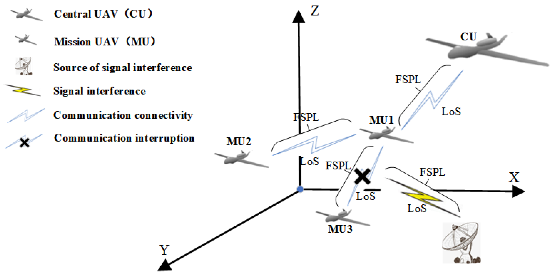
The remainder of this paper is organized as follows: Section 2 presents the system model; Section 3 presents the design and implementation of reconnaissance and coverage missions by HUAV swarms under different architectures based on the COAPF algorithm; in Section 4, an analysis of the simulations and results is presented with regard to the performance of HUAV swarms with centralized, distributed, and centralized–distributed architectures in executing missions using the COAPF algorithm; finally, Section 5 concludes the paper with a summary and outlook for future work.

2. System Model

This section presents the environmental model, HUAV swarm model, HUAV swarm architecture, and mathematical models.

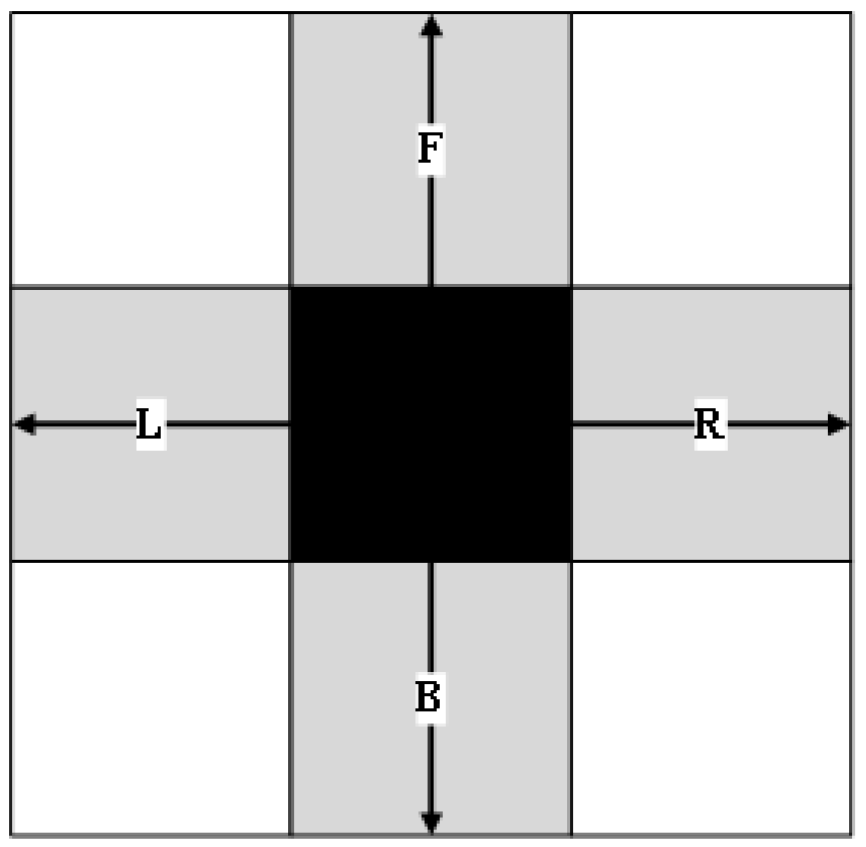
2.1. Environment Model

In outdoor missions such as disaster relief or military reconnaissance, UAVs are required to operate within designated target areas. Regarding environmental modeling, the grid-based approach has gained widespread academic favor due to its convenience in construction, representation, and storage [30]. This paper likewise adopts the grid-based method to construct the environmental model, establishing coverage rules and constraints based on the grid division of the mission space. To optimize UAV operations, the motion model is simplified and flight directions are restricted to ensure that the UAV flies along one of the four basic directions in the Von Neumann neighborhood at any given time (as illustrated in Figure 1), thereby achieving efficient coverage.
Assuming that the grid map of m × n comprises S S I N grid areas of signal interference sources, each with a signal interference intensity of S I s o u r c e , as the distance from these strong interference signal grids increases, the intensity of the interference signals continually attenuates during propagation in free space, with the attenuated signal intensity denoted as L L o S . This attenuation halts when it reaches the communication floor noise S I min of the entire area. With the regional location of a signal interference source denoted as ( x p , x q ) , p [ 1 , m ] , q [ 1 , n ] , the signal strength S I i j at the mission area location ( x i , x j ) , i [ 1 , m ] , j [ 1 , n ] can be expressed as follows:
D i s = ( x i x p ) 2 + ( x j x q ) 2
L L o S = 20 log 10 D i s + 20 log 10 f c + 20 log 10 ( 4 π / c ) F S P L + η L o S
S I i j = S I s o u r c e L L o S , i f S I i j > S I min S I min , e l s e
where D i s represents the distance over which the interference signal propagates in free space, f c denotes the carrier frequency of the radio wave, c signifies the speed of light waves, and η L o S represents the additional average path loss, which can be considered separately for scenarios such as suburban areas, urban areas, and high-density urban zones (city centers).
When a mission area grid ( x i , x j ) is within the effective interference range of S m strong interference signal sources, the interference intensity within that area is determined as the maximum value of the impact from all the interference sources, as follows:
S I i j = max ( S I i j k ) , k [ 1 , S m ] .

2.2. HUAV Swarm Model

Assuming a HUAV swarm consisting of one central UAV (CU) and N M U mission UAVs (MUs), all UAVs operate at a common altitude upon reaching the boundary of the target mission area, allowing the workspace to be rendered as a two-dimensional plane. In order to mathematically formulate an agent model, each UAV is defined by U = { P , V , R , S C , S t a t e , S I } , representing its state. Within this framework, P represents the latest known position matrix of all UAVs within the UAV’s knowledge, V is a vector that describes the magnitude and direction of the UAV’s velocity, R is a variable that characterizes the reconnaissance diameter of the UAV, S C is a communication status matrix that describes the connectivity between all UAVs based on the information known to each UAV, S t a t e is a matrix that captures the state of the environmental grid, as perceived by the UAV, and S I is a matrix that details the signal interference intensity within the environmental grid as known to the UAV.
Considering that both CU and MUs operate at high altitudes, line-of-sight (LoS) communication is adopted between CU-MU and MU-MU pairs while neglecting signal shadowing and scattering effects caused by terrestrial obstacles such as buildings, mountains, and foliage. In an environment with unknown communication interference, communication between UAVs necessitates comprehensive consideration of both the average path loss in LoS links and the variability in interference intensity across different regions. The crucial factor for ensuring communication connectivity among UAVs is whether the signal-to-noise ratio (SNR) reaches or exceeds a predetermined threshold S N R t h r e s h o l d that dictates the maximum effective communication distance between UAVs on the same plane. Specifically, the maximum normal communication distance between a CU and an MU is denoted as R max , and can be formulated as follows:
S N R t h r e s h o l d = P C U L max M N N o i s e
L max M = 20 log 10 R max + 20 log 10 f c + 20 log 10 ( 4 π / c ) + η L o s
R max = 10 ( P C U N N o i s e S N R t h r e s h o l d 20 log 10 f c 20 log 10 ( 4 π / c ) η L o s ) 20
In the above equations, S N R t h r e s h o l d represents the minimum SNR threshold required for normal communication, P C U is the transmission power (in db) of the CU’s wireless signal, N N o i s e signifies the calculation of the maximum communication interference within a rectangular area defined by the CU’s position and the target MU’s position considering all grid regions within this rectangle, and L max M and R max respectively represent the maximum average path loss and the maximum normal communication distance between the CU and any MU after S N R t h r e s h o l d , P C U and N N o i s e have been determined, while the process for calculating the maximum normal communication distance r max between any pair of MUs follows the same methodology. The communication status among HUAVs is illustrated in Figure 2.

2.3. HUAV Swarm Architectures

This paper explores three primary architectural frameworks for the control of HUAV swarms: centralized, distributed, and centralized–distributed.

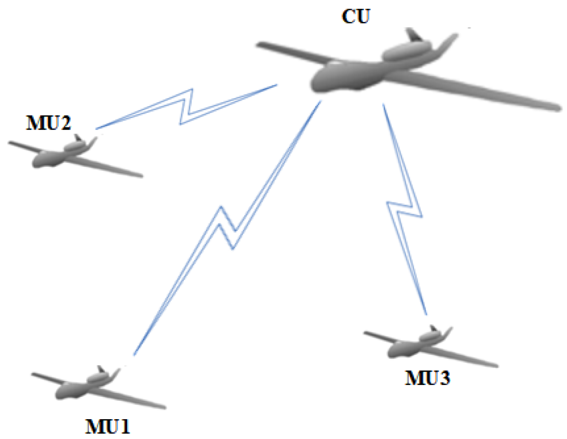
2.3.1. Centralized Architecture

Centralized architectures aew more prone to generating globally optimal strategies; however, their decision-making efficiency and anti-interference capabilities are limited. In unstable communication environments or when encountering unknown interference, disconnected MUs will struggle to relocate or re-establish control when communication between the CU and MUs is disrupted due to their lack of autonomous decision-making mechanisms. As illustrated in Figure 3, the CU is responsible for centralized control, with each MU executing missions based on commands issued by the CU, highlighting its vulnerability in situations of communication disruption.

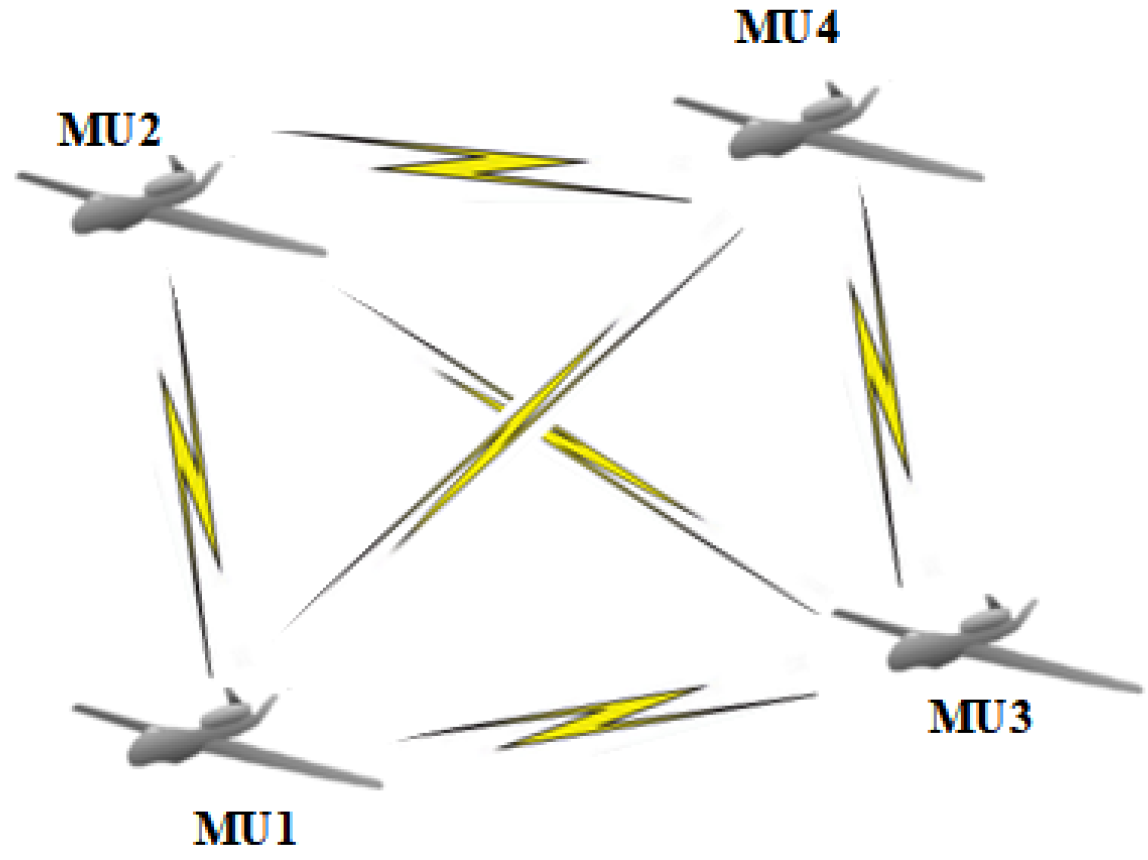
2.3.2. Distributed Architecture

In a distributed architecture, each UAV possesses independent decision-making capabilities, fostering collaboration within the swarm and enhancing robustness and adaptability. However, this advantage is accompanied by increased information processing burdens and potential resource wastage issues. In an environment with unknown communication interference, communication between the UAVs in a distributed system is susceptible to disruption, hindering information sharing and exacerbating inefficient resource utilization. As depicted in Figure 4, this architecture lacks a CU, with each MU executing missions independently based on available information.

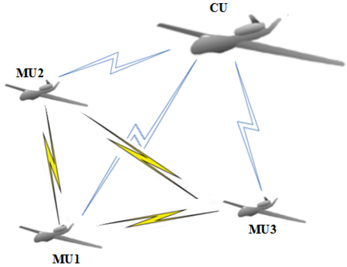
2.3.3. Centralized–Distributed Architecture

The control architecture of an HUAV swarm plays a decisive role in its flexibility and operational effectiveness. By fusing the attributes of centralized and decentralized architectures, centralized–distributed architectures mitigate the shortcomings of both while amplifying their respective strengths. As illustrated in Figure 5, a distributed system is established among MUs, while a CU is responsible for centralized management and global information sharing. Each UAV is able to not only share information in real-time but also to autonomously operate in a distributed mode, achieving an optimal balance between centralized control and decentralized execution.

2.4. Mathematical Model

The primary constraints considered in this paper are those of complete coverage and communication. Constraints such as collision avoidance among HUAVs are not the main focus of this study. This paper assumes that HUAVs possess online collision avoidance capabilities, and neglects the costs associated with collision avoidance; additionally, there is no limit on the hop count of signal propagation among HUAVs, and the communication cost is assumed to be in an ideal state.

2.4.1. Constraints

(1)
Complete Coverage Constraint
The HUAV swarm collaboratively executes reconnaissance and coverage missions until all target areas are fully covered. This constraint can be formulated as follows:
C o m p l e t e t = 1 , i f S i j t = 1 , i [ 1 , m ] , j [ 1 , n ] 0 , e l s e
In the above equation, S i j t represents an element within matrix S t a t e signifying the status of the known mission area grid ( x i , x j ) at time instant t for the UAV, while C o m p l e t e t serves as a decision variable for the UAV, indicating whether it has completed all reconnaissance and coverage missions by the time t. When C o m p l e t e t = 0 holds true, it implies that the swarm of HUAVs must continue to collaboratively execute reconnaissance and coverage missions at time t; conversely, when C o m p l e t e t = 1 holds true, it signifies that the HUAV swarm has successfully completed all reconnaissance and coverage missions by time t.
(2)
Communication Constraint
At any given time t, the communication status between HUAVs can be represented as follows:
D C O M i j t = 1 , i f ( D i s ( P i t , P j t ) R t , a n d i j ) o r ( D i s ( P i t , P j t ) > R t a n d D i s ( P j t , P k t ) R t a n d D i s ( P i t , P k t ) R t , a n d i j k ) , i , j , k [ 1 , N M U + 1 ] 0 , else
where D i s ( P i t , P j t ) denotes the distance between U A V i and U A V j at time t, R t represents the maximum communication distance between U A V i and U A V j at time t, and D C O M i j t is a decision variable indicating whether U A V i and U A V j are communicating normally at time t. When D C O M i j t = 1 holds true, it signifies that U A V i and U A V j are communicating normally at time t, while when D C O M i j t = 0 holds true it indicates that the communication between U A V i and U A V j at time t is interrupted.

2.4.2. Objective Function

In the process of real-time path planning, UAVs maximize their decision-making utility based on their own state and known environmental information, represented by a value function C. Given the known coverage status, motion status, communication status, and other pertinent information, the benefit of each UAV’s real-time path planning is calculated using the COAPF algorithm (detailed in Section 3). Here, p t represents the decision scheme determined by the current UAV at time t based on all currently available information. The objective function of the UAV can be formulated as follows:
arg ma x p t C ( P t , V t , S C t , S t a t e t , S I t )
where P t denotes the position matrix of all UAVs known to the UAV at time t, V t is a vector describing the magnitude and direction of the UAV’s velocity at time t. S C t is a matrix depicting the communication status among all UAVs within the known information of the UAV at time t, S t a t e t represents a matrix that characterizes the state of the environmental grid known to the UAV at time t, and S I t is a matrix that describes the signal interference strength of the environmental grid known to the UAV at time t.
Taking into account both the objective function and the constraints, the optimization problem of cooperative reconnaissance coverage for HUAV swarms can be formulated as the mathematical model shown below.
C t = arg ma x p t C ( P t , V t , S C t , S t a t e t , S I t ) subject to C o m p l e t e t = 1 , i f S i j t = 1 , i [ 1 , m ] , j [ 1 , n ] 0 , e l s e D C O M i j t = 1 , i f ( D i s ( P i t , P j t ) R t , a n d i j ) o r ( D i s ( P i t , P j t ) > R t a n d D i s ( P j t , P k t ) R t a n d D i s ( P i t , P k t ) R t , a n d i j k ) , i , j , k [ 1 , N M U + 1 ] 0 , else

3. HUAV Swarm Reconnaissance and Coverage Based on COAPF Algorithm

3.1. Design of COAPF Algorithm

Under the scenarios and objectives set forth in this paper, the HUAV swarm is required to swiftly cover mission areas characterized by varying levels of signal interference intensity. Given the limitations of traditional APF methods in defining targets, obstacles, and both attractive and repulsive force functions, this study innovatively proposes a COAPF algorithm. In the context of this paper, the attractive force is designed to expedite the UAVs’ coverage of unexplored regions, while the repulsive force prevents redundant coverage of already surveyed areas. Each grid is treated as an independent target, with the UAVs constructing an artificial potential field based on environmental information to plan their paths in real-time. As detailed in Section 2, the UAVs have four directional options (up, down, left, right) for path planning within the gridded environment.
Contrary to conventional approaches, this paper reverses conventional wisdom by postulating that the magnitudes of the attractive/repulsive forces increase as the agents approach attractive/repulsive targets. The UAVs integrate the grid states in all directions, calculate the combined attractive and repulsive forces, and subsequently determine the optimal flight direction. This approach enables the UAV swarm to dynamically adapt to the changing environment and efficiently cover the entire mission area while minimizing overlap and maximizing coverage efficiency.
In the COAPF algorithm, the gravitational potential field function of a UAV can be represented as U a t t D i r ( X ) , while the repulsive potential field function can be denoted as U r e p D i r ( X ) . The specific definitions are as follows:
U a t t D i r ( X ) = 1 2 i = 1 F G r i d N D i r k a t t × d ( X , X i ) 2
where D i r represents one of the four flight directions chosen by the UAV, k a t t is the gravitational field constant, F G r i d N D i r denotes the number of uncovered grid cells in direction D i r of the UAV, and d ( X , X i ) is the distance between the UAV and the i-th uncovered grid area in direction D i r .
U r e p D i r ( X ) = 1 2 i = 1 T G r i d N D i r k r e p × d ( X , X i ) 2
In the above equation, k r e p represents the repulsive field constant, T G r i d N D i r denotes the number of already-covered grid cells in the direction D i r of the UAV, and d ( X , X i ) is the distance between the UAV and the i-th already-covered grid area in direction D i r .
By taking the negative gradient of the above equation, the resulting gravitational force F a t t D i r ( X ) and repulsive force F r e p D i r ( X ) are as follows:
F a t t D i r ( X ) = i = 1 F G r i d N D i r k a t t × d ( X , X i ) 3 ,
F r e p D i r ( X ) = i = 1 T G r i d N D i r k r e p × d ( X , X i ) 3 .
Based on the above, the resulting force F D i r ( X ) experienced by the UAV is
F D i r ( X ) = min F D i r ( X ) , i f F a t t D i r ( X ) = 0 F a t t D i r ( X ) F r e p D i r ( X ) , else .
Due to the presence of both positive and negative values, separate procedures are necessary to normalize the resulting forces in the four directions. The resulting normalized force in each direction range within [ 0 , 1 ] , and can be expressed as F N o r D i r ( X ) :
F N o r D i r ( X ) = max ( F D i r ( X ) ) F D i r ( X ) , i f F D i r ( X ) < 0 F D i r ( X ) max ( F D i r ( X ) ) , e l i f F D i r ( X ) 0 ( F D i r ( X ) + min ( F D i r ( X ) ) ) max ( F D i r ( X ) ) min ( F D i r ( X ) ) , e l s e .

3.2. COAPF Algorithm for Different Architectures

This paper aims to explore the efficiency differences of HUAV swarms when employing various architectural frameworks (centralized, distributed, and centralized–distributed) to execute reconnaissance and coverage missions within an unknown environment with communication interference. To achieve this objective, we adopt the same COAPF algorithm as the core strategy while comprehensively evaluating the performance of each architecture from multiple dimensions.

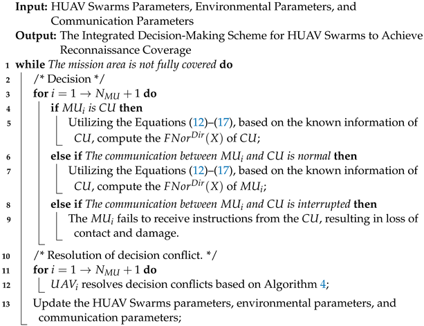
3.2.1. COAPF Algorithm Oriented towards Centralized Architecture

Under the centralized architecture, all decision-making and coordination processes are concentrated within a central control unit, enabling mission planning and execution through centralized processing and distribution of global information. For the HUAV swarm operating under the centralized architecture, this paper elaborates on the specific process of executing reconnaissance and coverage missions utilizing the COAPF algorithm, which is summarized and presented as Algorithm 1.

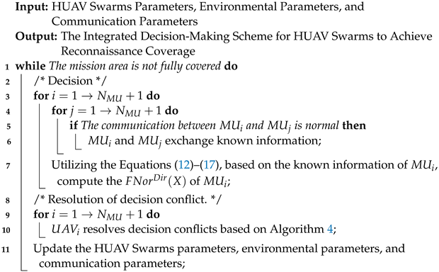
3.2.2. COAPF Algorithm Oriented towards Distributed Architecture

The distributed architecture emphasizes autonomy and local information exchange among units, enhancing the system’s robustness and flexibility through a decentralized decision-making mechanism that allows the HUAV swarm to adapt complex and varying communication interference environments. For the HUAV swarm under the distributed architecture, this paper elaborates on the specific process of executing reconnaissance and coverage missions using the COAPF algorithm, which is summarized and presented as Algorithm 2.

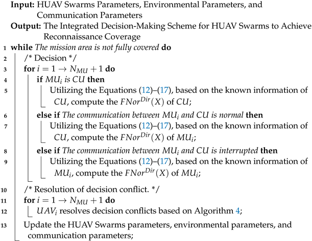
3.2.3. COAPF Algorithm Oriented towards Centralized–Distributed Architecture

The centralized–distributed architecture skillfully integrates the characteristics of both centralized and distributed frameworks, retaining the advantages of global coordination while granting local units a certain degree of autonomous decision-making capabilities. This approach aims to maintain the overall system effectiveness while improving its ability to respond to uncertainties and dynamic changes. For the HUAV swarm under the centralized–distributed architecture, this paper details the specific process of executing reconnaissance and coverage missions using the COAPF algorithm, which is summarized and presented as Algorithm 3.
Algorithm 1: COAPF Algorithm Based on Centralized Architecture
Electronics 13 04067 i001
Algorithm 2: COAPF Algorithm Based on Distributed Architecture
Electronics 13 04067 i002
Algorithm 3: COAPF Algorithm Based on the Distributed–Collective Architecture
Electronics 13 04067 i003

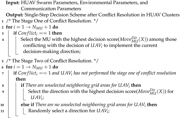
3.2.4. Resolving Decision Conflicts

In addressing cooperative optimization with HUAVs, it is imperative to consider the decision conflicts among MUs. Let N M U T i represent the number of MUs that are normally communicating with M U T i , i [ 1 , N M U ] and let P j , j [ 1 , N M U T i ] designate the grid position where MUs which are communicating normally with M U T i decide to move forward:
C o n f l i c t i = 1 , i f P j = P k , j , k [ 1 , N M U T i ] 0 , else .
If C o n f l i c t i equals 0, it indicates that no decision conflict has occurred among M U i ; however, if C o n f l i c t i equals 1, it signifies that a decision conflict has arisen in M U i . In such cases, the MU with the highest resultant force F N o r D i r ( X ) among the conflicting MUs is selected to execute its current decision. The remaining MUs must re-evaluate their movement directions until all uncovered neighboring grid areas within their current scope have been traversed. If decision conflicts persist across all uncovered neighboring grid areas, then the MUs randomly select a direction towards an already covered neighboring grid. The process of decision conflict resolution within the HUAV swarm is outlined in Algorithm 4. Based on the aforementioned decision conflict resolution algorithm, multiple UAVs can be effectively prevented from redundantly performing reconnaissance and coverage missions on the same grid area at the same time, thereby reducing ineffective expenditures by the HUAV swarm.
Algorithm 4: Decision Conflict Resolution Algorithm
Electronics 13 04067 i004

4. Simulations and Results Analysis

4.1. Simulation Design

This section establishes the simulation environment used to validate the effectiveness of the proposed method. The relevant parameter configurations are detailed in Table 2, encompassing the specific details of the wireless communication, HUAV swarms, and algorithms [7]. The simulation hardware was based on a twelfth-generation Intel Core i9-12900K processor supplemented with 64 GB of RAM. The software environment consisted of a Windows 10 operating system, Python 3.8, and PyCharm 2018.3.7.
To validate the generalization capability of the algorithm, a comparative simulation test was designed encompassing various HUAV swarm sizes (5, 10, 30, 50, and 100) and varying signal interference intensities within the mission area (interference source percentages of 0%, 0.2%, 0.5%, 2%, and 5%). Each simulation group assessed the algorithm’s performance under distinct conditions, with signal interference modulated by the proportion of interference sources gridded within the mission area while ensuring no more than one interference source per grid. Communication challenges were quantitatively characterized through the relationship between grid size and the maximum communication distance of HUAVs under average interference, with the detailed configurations outlined in Table 3.

4.2. Comparative Simulations

To validate the performance differences among HUAV swarms employing centralized, distributed, and centralized–distributed architectures in executing reconnaissance and coverage missions within an unknown environment with communication interference, this article employs mission completion time, coverage speed, and communication recovery times as the key metrics. A comparative analysis was conducted to evaluate the performance of the COAPF algorithm under the three tested architectures.

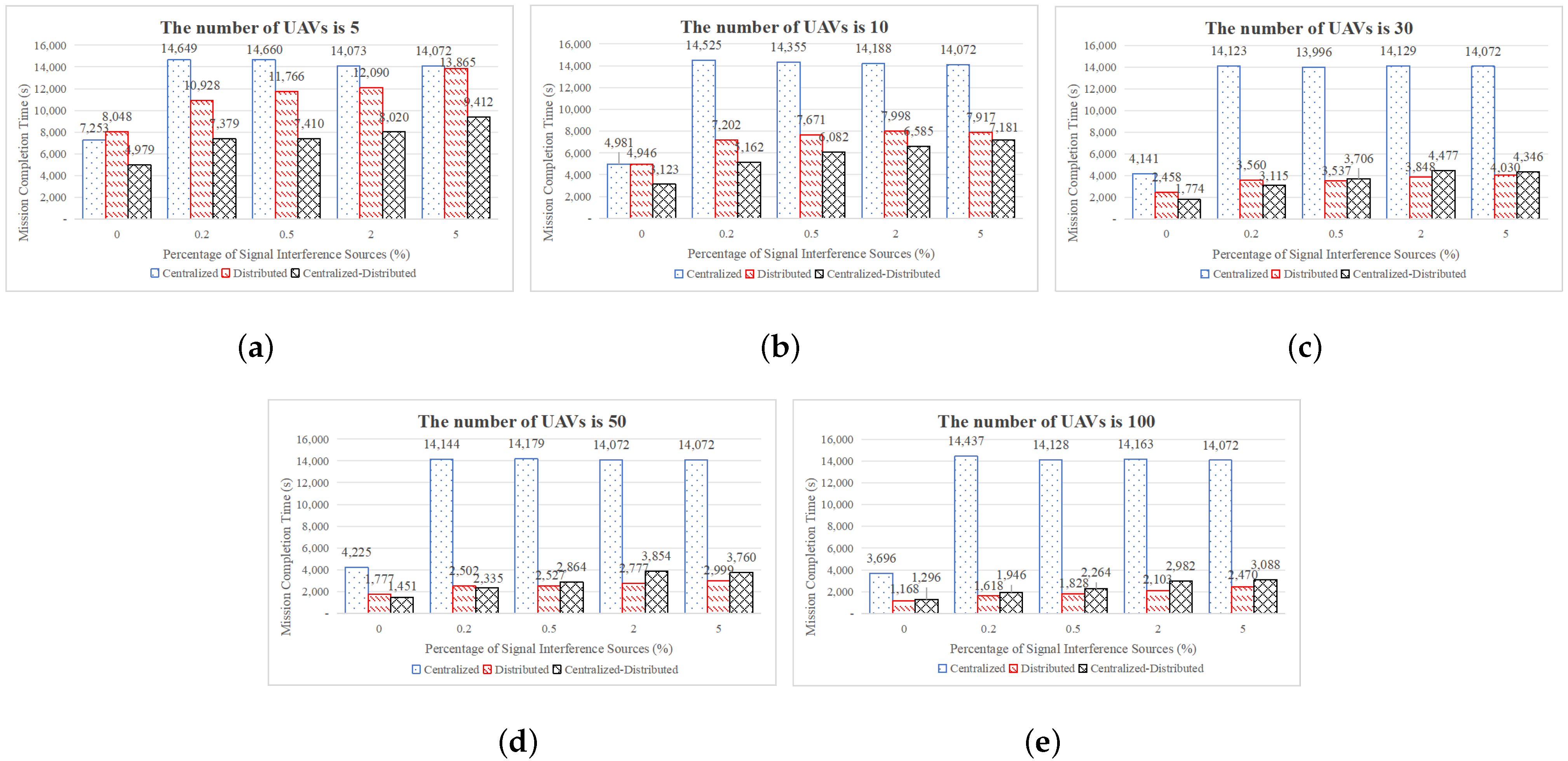
4.2.1. Comparison of Total Area Coverage Time

To ensure the reliability of our simulation results, each simulation group underwent ten random environmental initializations, with the mean of the ten completion times taken as the final mission completion time. Figure 6 compares the completion time results for HUAV swarms executing reconnaissance and coverage missions based on centralized, distributed, and centralized–decentralized architectures for HUAV swarm sizes of 5, 10, 30, 50, and 100 and signal interference source percentages of 0%, 0.2%, 0.5%, 2%, and 5%.
Regarding the variation in the number of signal interference sources, as long as there are signal interference sources within the mission area, the time to mission completion of the centralized architecture is significantly longer that of the distributed and centralized–distributed architectures while maintaining a relatively stable duration. This is attributed to the fact that the MUs within the HUAV swarm lack decision-making capabilities under the centralized architecture. Thus, when communication between the MUs and the CU is disrupted, the MUs are deemed to be compromised, leaving only the CU to continue executing the mission. In distributed and centralized–distributed architectures, the mission completion time escalates accordingly as the number of signal interference sources increases until the average signal interference intensity within the mission area attains a specific threshold, at which point the mission completion time tends to stabilize.
Regarding changes in the scale of the HUAV swarm, when the swarm size is relatively small at 5 or 10 units, the centralized–distributed architecture achieves mission completion in a shorter time compared to the distributed architecture. When the swarm size reaches 30 units, the centralized–distributed architecture still outperforms the distributed architecture in terms of mission completion time, especially when the proportion of signal interference sources is low at 0% or 0.2%; however, as the proportion of signal interference sources increases to higher levels of 0.5%, 2%, and 5%, the centralized–distributed architecture requires more time to complete the mission than the distributed architecture. For larger swarm sizes of 50 and 100 units, the centralized–distributed architecture consistently exhibits longer mission completion times compared to the distributed architecture.

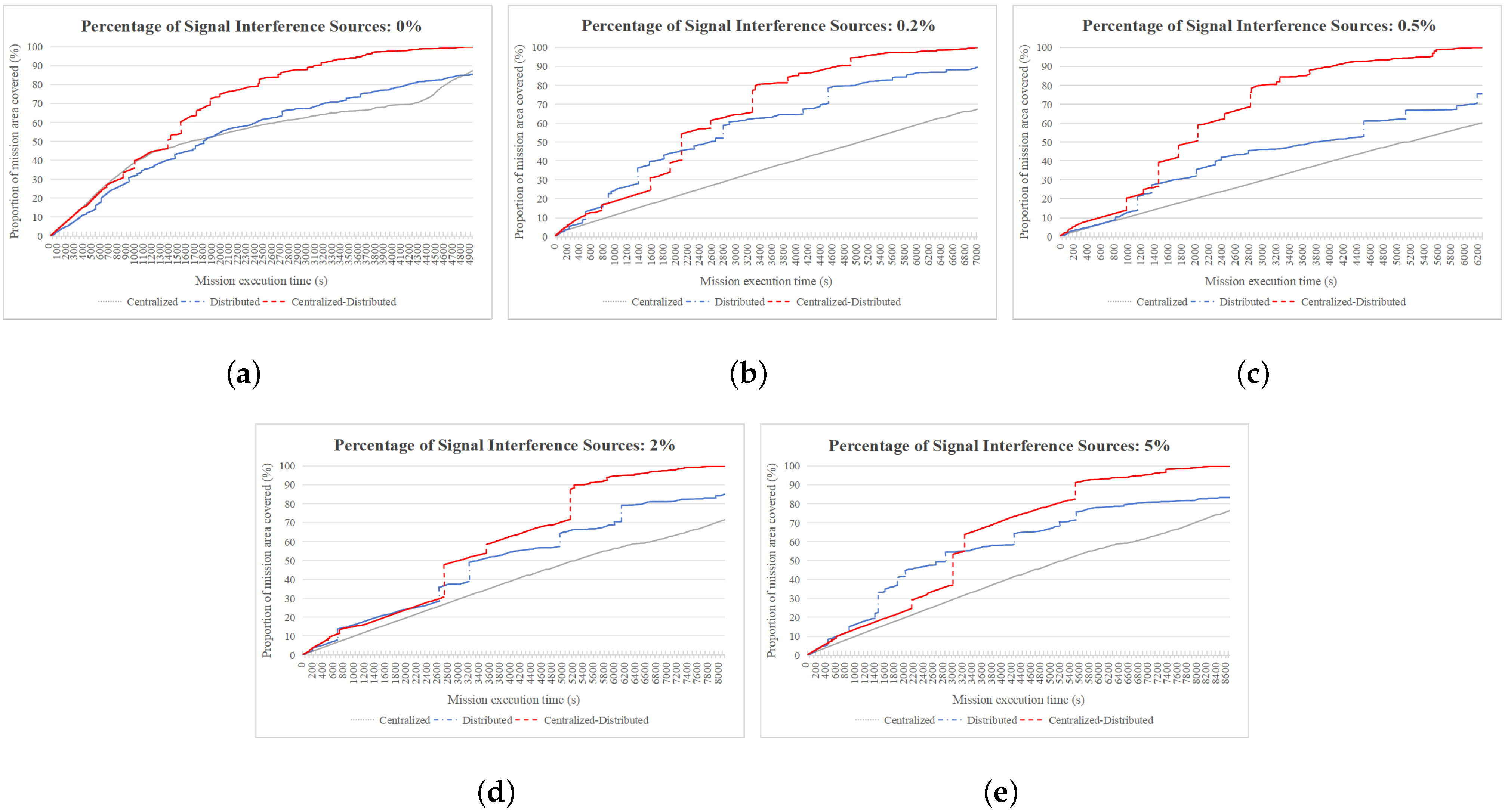
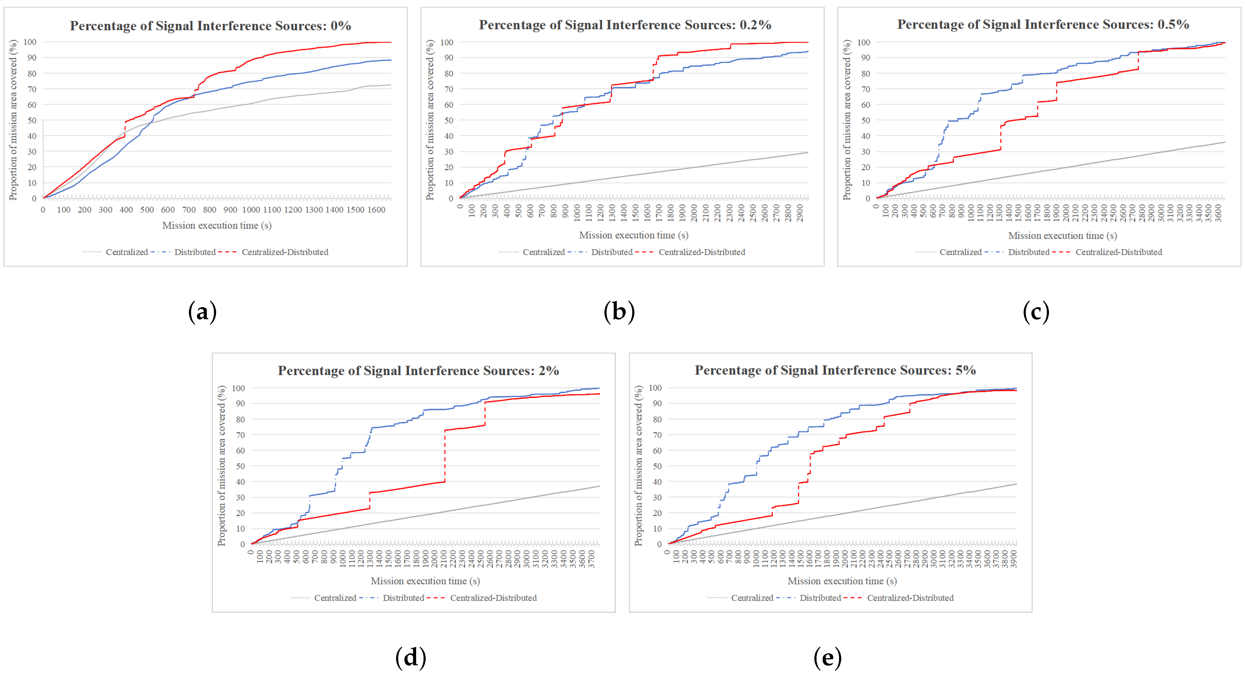
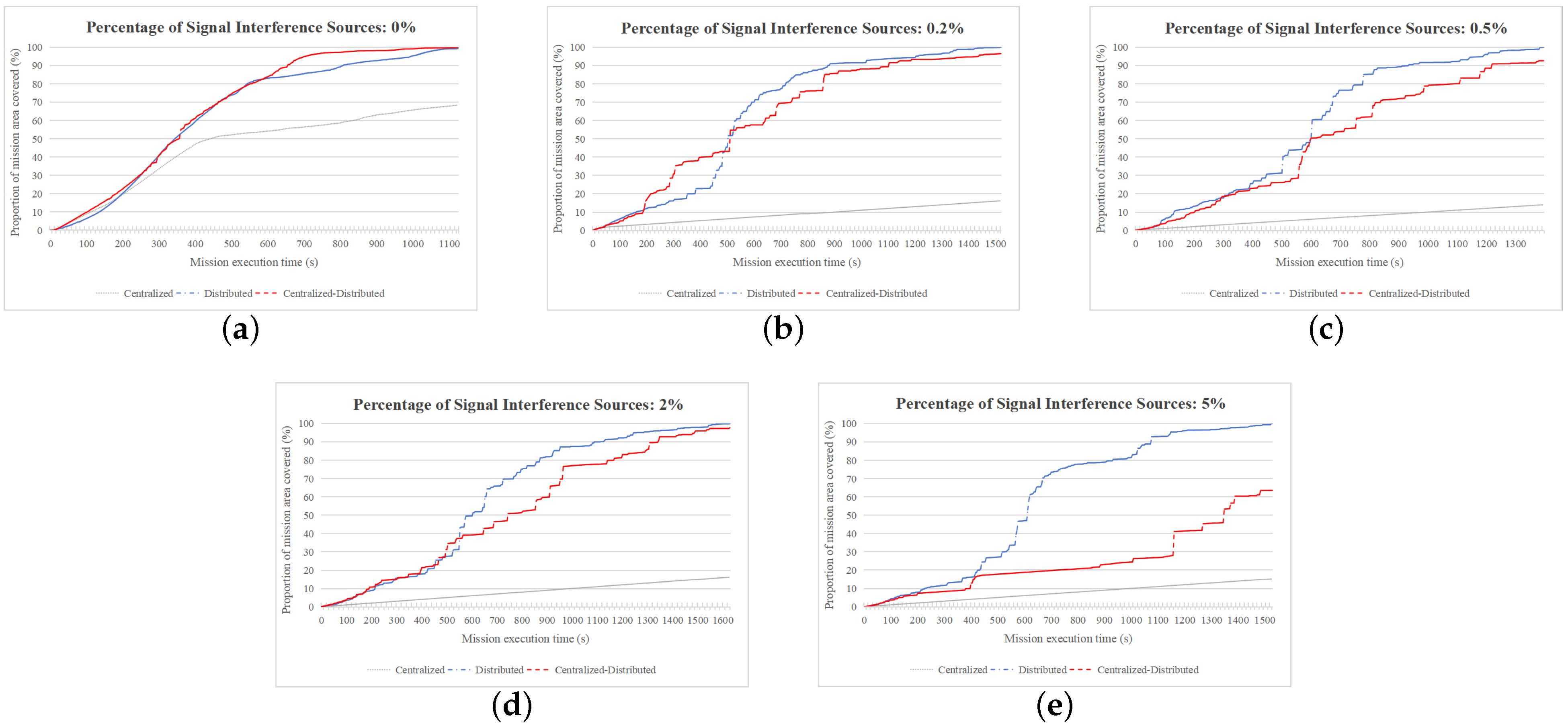
4.2.2. Comparison of Regional Coverage Speeds

To investigate the speed of HUAV swarms in executing regional coverage under varying signal interference intensities and swarm sizes, we conducted simulation analyses with signal interference source percentages of 0%, 0.2%, 0.5%, 2%, and 5% and HUAV swarm sizes of 5, 30, and 100. A speed comparison of HUAV swarms executing reconnaissance and coverage missions based on centralized, distributed, and centralized–decentralized architectures is presented in Figure 7, Figure 8 and Figure 9:
As is evident from Figure 7, when the size of the HUAV swarm is 5, the centralized–distributed architecture outperforms the centralized and distributed architectures in swiftly completing reconnaissance coverage of the mission area irrespective of the number of signal interference sources. Notably, the reconnaissance speed among the three architectures is comparable during the initial stages of COAPF algorithm execution, with the centralized–distributed architecture only surpassing the centralized and distributed ones in the mid-to-late phases. Furthermore, the speed of the HUAV swarm with the distributed architecture increases with an increasing number of signal interference sources, mirroring a similar trend on the part of the centralized–distributed architecture. Conversely, the centralized architecture exhibits anomalous behavior, with its mission execution speed remaining largely consistent and significantly lower than the other three architectures except when there are no signal interference sources in the mission area. This anomaly stems from the lack of decision-making capabilities of the MUs within the centralized architecture.
Figure 8 reveals that the centralized–distributed architecture does not confer a significant advantage over the distributed architecture when the HUAV swarm size is 30, while the centralized-distributed architecture retains its edge over the distributed architecture at lower signal interference levels (0% and 0.2%). A notable disparity in coverage speed emerges as the number of signal interference sources increases to 0.5%, 2%, and 5%. Importantly, the speed of the distributed architecture-based HUAV swarm escalates with the rising number of signal interference sources, paralleling the trend observed for the centralized–distributed architecture. Again, the centralized architecture behaves anomalously, with its mission execution speed consistently remaining at a considerably slower rate than the other two architectures except when there are no signal interference sources.
Figure 9 demonstrates that with an HUAV swarm size of 100, the centralized–distributed architecture offers an advantage over the distributed architecture solely when there are no signal interference sources (0%). When the number of signal interference sources increases to 0.2%, 0.5%, 2%, and 5%, a pronounced disparity in coverage speed emerges between the centralized–distributed and distributed architectures. Notably, the speed of the HUAV swarm with the distributed architecture intensifies with the proliferation of signal interference sources, echoing the trend observed for the centralized–distributed architecture. Again, the centralized architecture exhibits anomalous behavior, with its mission execution speed staying uniform and markedly slower than the other two architectures except in the absence of signal interference sources in the mission area.

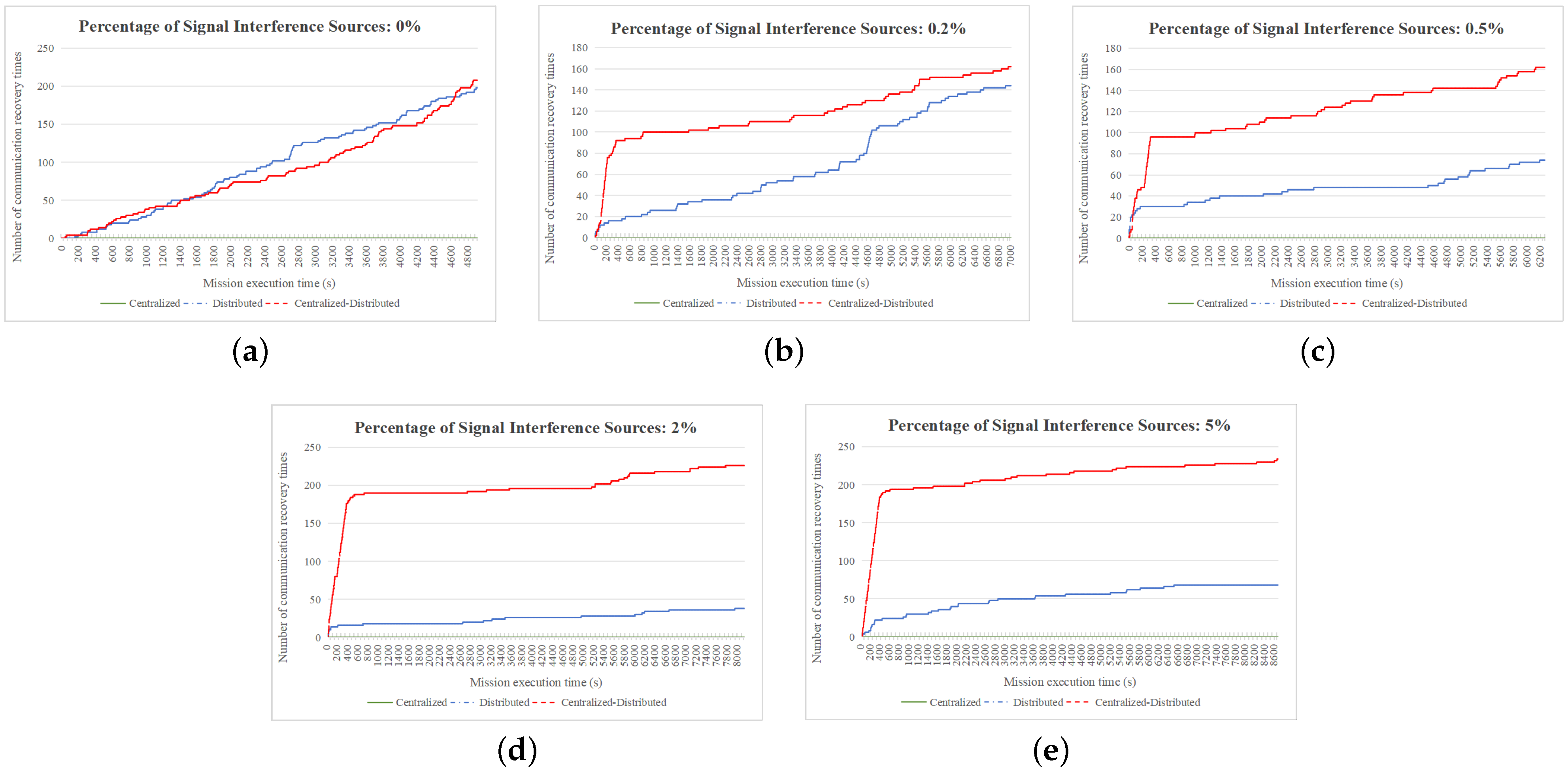
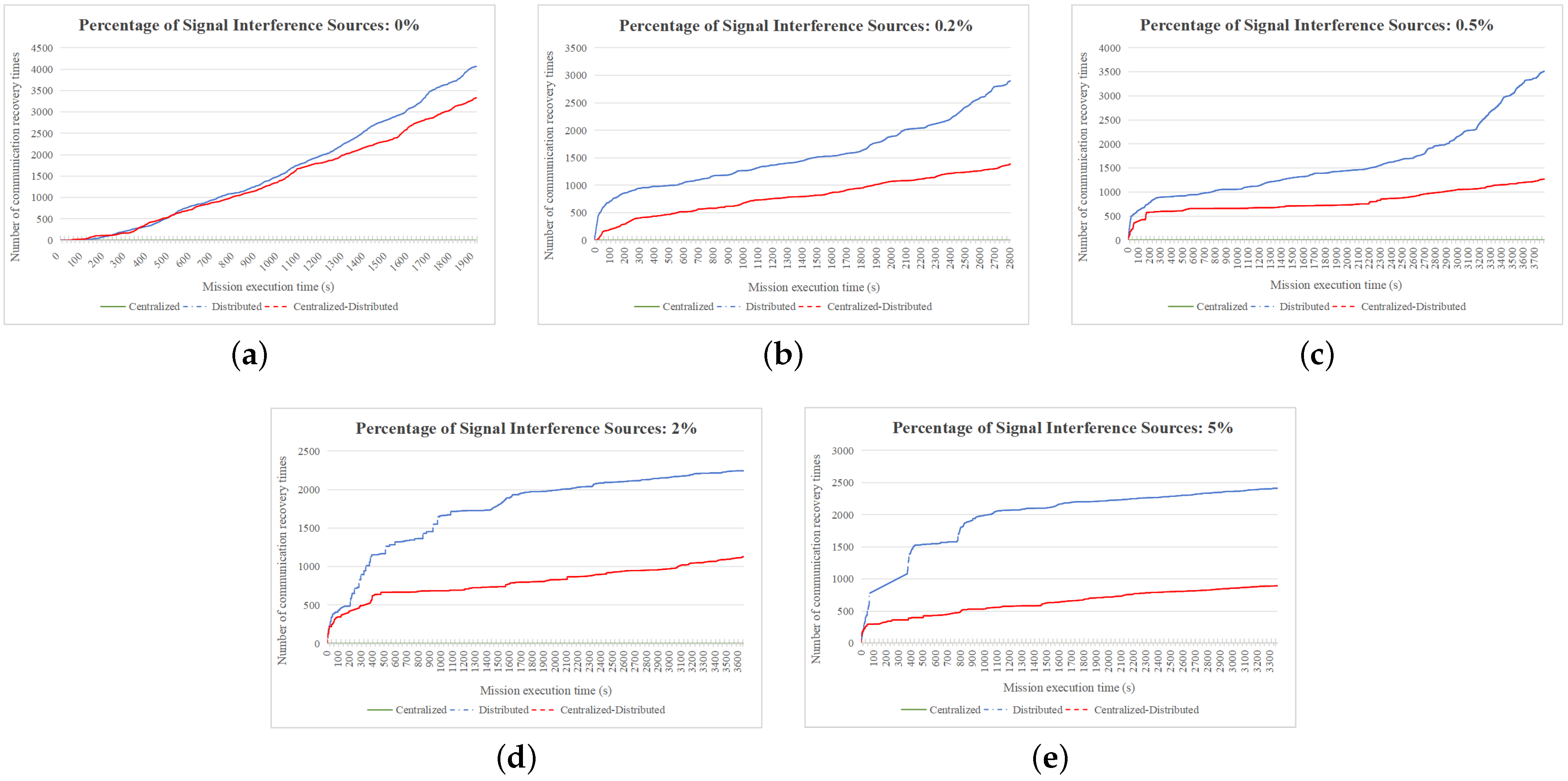
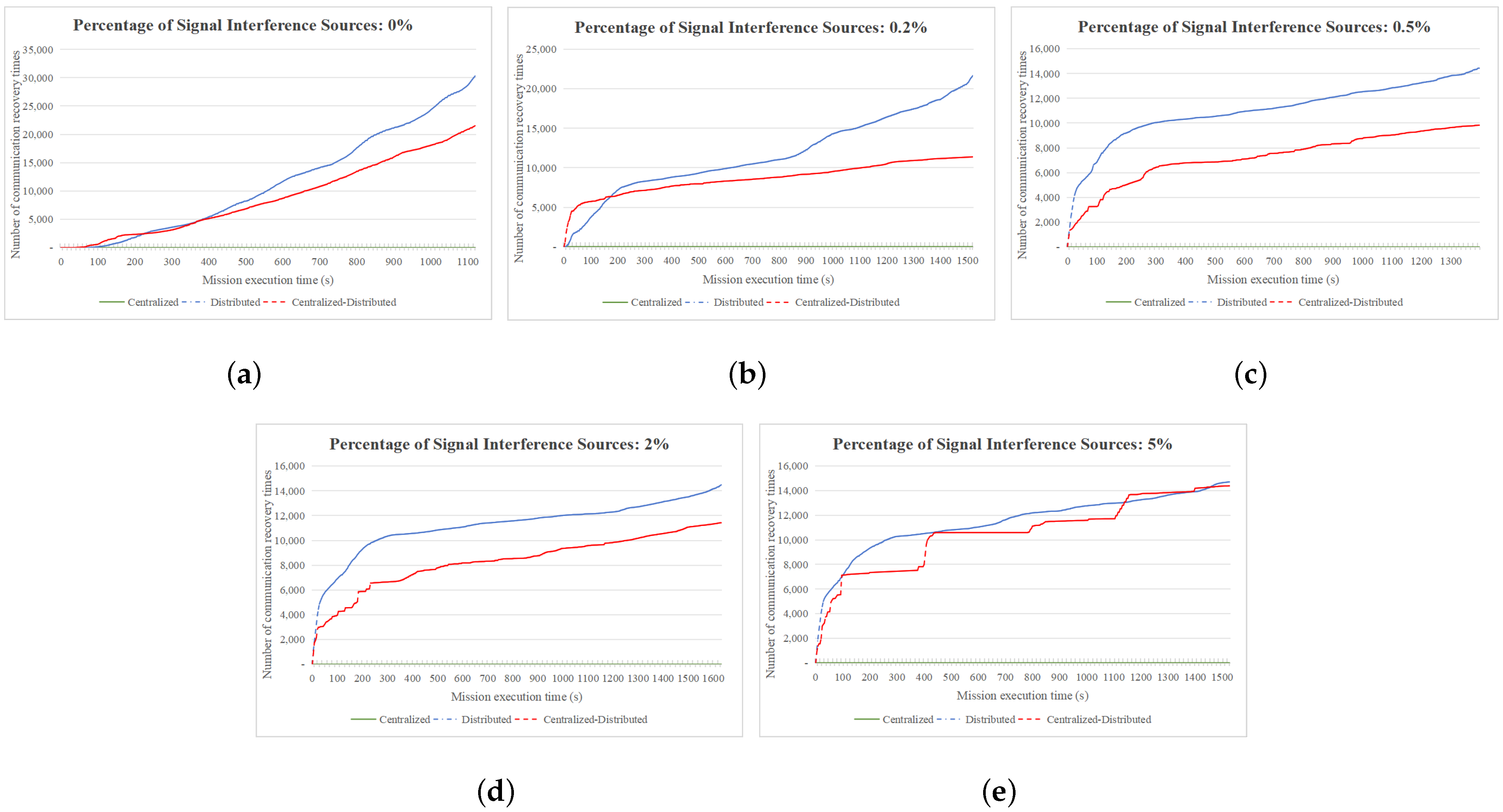
4.2.3. Comparison of Communication Recovery Times

To investigate the number of communication recoveries after disruptions during regional coverage missions executed by HUAV swarms under varying signal interference intensities and swarm sizes, we conducted simulation analyses with different proportions of signal interference sources at 0%, 0.2%, 0.5%, 2%, and 5% and with HUAV swarm sizes of 5, 30, and 100. A comparison of communication recovery times for reconnaissance and coverage missions performed by HUAV swarms based on centralized, distributed, and centralized–distributed architectures is presented in Figure 10, Figure 11 and Figure 12.
As illustrated in Figure 10, when the size of the HUAV swarm is 5 the HUAV swarm based on the centralized–distributed architecture achieves more communication recovery times compared to the distributed architecture during the process of achieving full coverage of the mission area. Notably, unlike the distributed architecture, the number of communication recoveries for the HUAV swarm with the centralized–distributed architecture exhibits a growth trend proportional to the increase in the number of signal interference sources. For the HUAV swarm operating under a centralized architecture, the MUs are deemed to be damaged when communication between MUs and the CU is interrupted, and no communication recovery occurs.
Figure 11 reveals that when the HUAV swarm size expands to 30, the HUAV swarm with the distributed architecture accomplishes more communication recoveries during full coverage of the mission area than its centralized–distributed counterpart. Notably, in contrast to the centralized–distributed architecture, the number of communication recoveries for the HUAV swarm with the distributed architecture shows an increasing trend with an escalating number of signal interference sources.
Figure 12 indicates that when the HUAV swarm reaches a size of 100, the HUAV swarm with the distributed architecture achieves more communication recoveries during the full coverage process than the centralized–distributed architecture. It is noteworthy that the number of communication recoveries for the HUAV swarm with the distributed architecture first increases and then decreases relative to the centralized–distributed architecture as the number of signal interference sources increases.

4.2.4. Analysis of Significance

To ensure the accuracy and reliability of our research conclusions, we conducted t-tests on the completion times of reconnaissance coverage missions executed by the HUAV swarms based on different architectures. The significance level was set at p = 0.05, and the test results are presented in Table 4. In the table, the symbols “+”, “−”, and “=” respectively denote that the completion time of reconnaissance coverage missions by HUAV swarms based on the centralized, distributed, and centralized–distributed architectures is significantly better than, significantly worse than, or not significantly different from that of the other architectures in the corresponding scenario designs. The notations B, S, and respectivelyW represent the counts of “+,” “−”, and “=” in different simulation scenario settings. The expression B-W indicates the difference in the number of simulation cases where the current architecture significantly outperformed the compared architecture, with a larger value of B-W reflecting superior performance of the architecture in the t-test. In Table 4, the notation C-D represents comparison of the t-test results between the centralized and distributed architectures, C-CD denotes comparison between the centralized and distributed–centralized architectures, D-C stands for comparison between the distributed and centralized architectures, D-CD indicates comparison between the distributed and distributed–centralized architectures, CD-C signifies comparison between the distributed–centralized and centralized architectures, and CD-D represents comparison between the distributed–centralized and distributed architectures.
As is evident from Table 4, the HUAV swarms exhibit varying advantages and disadvantages in reconnaissance coverage missions under different communication interference and unknown environments based on their underlying architectures. The distributed architecture demonstrates superior performance when the HUAV swarm size is large and the proportion of signal interference sources is high; specifically, at swarm sizes of 50 and 100, the B-W values are both greater than 0, and the simulation environments where B is chosen all correspond to medium-to-high interference scenarios with signal interference source proportions of 0.5%, 2%, and 5%. Conversely, the centralized–distributed architecture performs better when the HUAV swarm size is small and the proportion of signal interference sources is low; at swarm sizes of 5 and 10, the B-W values are also greater than 0, and this architecture outperforms the other two regardless of whether the environment is characterized by strong interference. Due to its lack of decision-making capability, the centralized architecture performs poorly in all scenarios where signal interference is present.
In summary, when the signal interference intensity in the mission area is high and the number of HUAVs is sufficient, a distributed architecture is more efficient for HUAV swarms executing reconnaissance coverage missions. When the number of HUAVs is limited and the signal interference intensity in the mission area is unknown, a centralized–distributed architecture is more effective and stable for HUAV swarms performing reconnaissance coverage missions.

5. Conclusions

This paper has explored the communication disruption challenges confronted by HUAV swarms when executing reconnaissance and coverage missions in environments with unknown communication interference and examined how the distinct characteristics of various control architectures significantly impact the efficiency and effectiveness of mission completion. Addressing the current research gap in understanding the impact of communication interference, this study establishes a HUAV swarm communication model that incorporates communication interference so as to more precisely simulate and reflect real-time communication states. To overcome the limitations of traditional APF methods in defining objectives, obstacles, and attractive/repulsive force functions, this paper innovatively proposes a COAPF algorithm. On the basis of this algorithm, the performance of HUAV swarms under three different control architectures (centralized, distributed, and centralized–distributed) is compared from multiple dimensions, including mission completion time, area coverage speed, and communication recovery time. Our simulation results indicate that the distributed architecture exhibits notable advantages in handling large-scale swarms and strong communication interference, enabling more effective communication disruption mitigation and ensuring efficient mission completion. Conversely, the centralized–distributed architecture may be more suitable for small-scale swarms and weaker interference environments, where its flexibility and local decision-making capabilities can contribute to improved mission execution efficiency. Due to its lack of distributed decision-making capabilities, the centralized architecture generally demonstrates lower mission execution efficiency in the presence of communication interference. Future research can expand on and deepen the current study in terms of the following aspects:
(1) Multi-source interference modeling: The communication interference model proposed in this paper primarily considers a single type of interference source; in practical applications, however, interference may stem from multiple sources, including both human-induced and natural interference. Therefore, constructing a more complex and comprehensive multi-source interference model that can more accurately simulate real-world communication environments represents an important direction for future research.
(2) Cross-architecture collaboration: While this paper has compared the performance differences among three distinct control architectures, practical applications may require dynamically switching between or combining multiple architectures based on mission requirements and environmental conditions. Thus, exploring collaborative control strategies across architectures to fully leverage the strengths of each will be crucial for enhancing the overall performance of HUAV swarms.

Author Contributions

Investigation, Y.F.; methodology, Y.F.; validation, Y.F.; writing—original draft preparation, Y.F.; writing—review and editing, Y.F., B.C., Y.Z., F.H., C.L. and Y.L.; supervision, B.C., Y.Z., F.H., C.L. and Y.L. All authors have read and agreed to the published version of the manuscript.

Funding

This research was funded by the National Natural Science Foundation of China under grant numbers 62176122 and 62061146002.

Data Availability Statement

All data are contained within the article.

Conflicts of Interest

The authors declare no conflicts of interest.

Abbreviations

The following abbreviations are used in this manuscript:
UAVUnmanned Aerial Vehicle
HUAVHeterogeneous Unmanned Aerial Vehicle
APFArtificial Potential Field
COAPFCoverage-Oriented Artificial Potential Field
SISignal Interference
CUCentral UAV
MUMission UAV
LoSLine-of-Sight
SNRSignal-to-Noise Ratio

References

  1. Sajid, M.; Mittal, H.; Pare, S.; Prasad, M. Routing and scheduling optimization for UAV assisted delivery system: A hybrid approach. Appl. Soft Comput. 2022, 126, 109225. [Google Scholar] [CrossRef]
  2. Peng, C.; Qiu, S. A decomposition-based constrained multi-objective evolutionary algorithm with a local infeasibility utilization mechanism for UAV path planning. Appl. Soft Comput. 2022, 118, 108495. [Google Scholar] [CrossRef]
  3. Stolfi, D.H.; Brust, M.R.; Danoy, G.; Bouvry, P. A competitive Predator–Prey approach to enhance surveillance by UAV swarms. Appl. Soft Comput. 2021, 111, 107701. [Google Scholar] [CrossRef]
  4. Mazaherifar, A.; Mostafavi, S. UAV placement and trajectory design optimization: A survey. Wirel. Pers. Commun. 2022, 124, 2191–2210. [Google Scholar] [CrossRef]
  5. Saraswat, D.; Bhattacharya, P.; Singh, A.; Verma, A.; Tanwar, S.; Kumar, N. Secure 5G-assisted UAV access scheme in IoBT for region demarcation and surveillance operations. IEEE Commun. Stand. Mag. 2022, 6, 58–66. [Google Scholar] [CrossRef]
  6. Dong, Q.; Zhang, J. Distributed cooperative complete coverage path planning in an unknown environment based on a heuristic method. Unmanned Syst. 2024, 12, 149–160. [Google Scholar] [CrossRef]
  7. Yin, D.; Yang, X.; Yu, H.; Chen, S.; Wang, C. An air-to-ground relay communication planning method for UAVs swarm applications. IEEE Trans. Intell. Veh. 2023, 8, 2983–2997. [Google Scholar] [CrossRef]
  8. Shi, Y.; Yi, C.; Chen, B.; Yang, C.; Zhu, K.; Cai, J. Joint online optimization of data sampling rate and preprocessing mode for edge–cloud collaboration-enabled industrial IoT. IEEE Internet Things J. 2022, 9, 16402–16417. [Google Scholar] [CrossRef]
  9. Alsuhli, G.; Fahim, A.; Gadallah, Y. A survey on the role of UAVs in the communication process: A technological perspective. Comput. Commun. 2022, 194, 86–123. [Google Scholar] [CrossRef]
  10. Shi, Y.; Yi, C.; Wang, R.; Wu, Q.; Chen, B.; Cai, J. Service migration or task rerouting: A two-timescale online resource optimization for MEC. IEEE Trans. Wirel. Commun. 2023. [Google Scholar] [CrossRef]
  11. Li, Y.; Aghvami, A.H. Radio Resource Management for Cellular-Connected UAV: A Learning Approach. IEEE Trans. Commun. 2023, 71, 2784–2800. [Google Scholar] [CrossRef]
  12. Chopra, S.; Egerstedt, M. Spatio-temporal multi-robot routing. Automatica 2015, 60, 173–181. [Google Scholar] [CrossRef]
  13. Morgan, D.; Subramanian, G.P.; Chung, S.J.; Hadaegh, F.Y. Swarm assignment and trajectory optimization using variable-swarm, distributed auction assignment and sequential convex programming. Int. J. Robot. Res. 2016, 35, 1261–1285. [Google Scholar] [CrossRef]
  14. Oh, H.; Shin, H.S.; Kim, S.; Chen, W.H. Communication-aware trajectory planning for unmanned aerial vehicles in urban environments. J. Guid. Control Dyn. 2018, 41, 2271–2282. [Google Scholar] [CrossRef]
  15. Fei, B.; Bao, W.; Zhu, X.; Liu, D.; Men, T.; Xiao, Z. Autonomous Cooperative Search Model for Multi-UAV With Limited Communication Network. IEEE Internet Things J. 2022, 9, 19346–19361. [Google Scholar] [CrossRef]
  16. Ozkan, O. Optimization of the distance-constrained multi-based multi-UAV routing problem with simulated annealing and local search-based matheuristic to detect forest fires: The case of Turkey. Appl. Soft Comput. 2021, 113, 108015. [Google Scholar] [CrossRef]
  17. Yang, L.; Meng, F.; Zhang, J.; Hasna, M.O.; Di Renzo, M. On the performance of RIS-assisted dual-hop UAV communication systems. IEEE Trans. Veh. Technol. 2020, 69, 10385–10390. [Google Scholar] [CrossRef]
  18. Liu, X.; Liu, Y.; Chen, Y. Machine learning empowered trajectory and passive beamforming design in UAV-RIS wireless networks. IEEE J. Sel. Areas Commun. 2020, 39, 2042–2055. [Google Scholar] [CrossRef]
  19. Li, M.; Cheng, N.; Gao, J.; Wang, Y.; Zhao, L.; Shen, X. Energy-efficient UAV-assisted mobile edge computing: Resource allocation and trajectory optimization. IEEE Trans. Veh. Technol. 2020, 69, 3424–3438. [Google Scholar] [CrossRef]
  20. Xu, C.; Xu, M.; Yin, C. Optimized multi-UAV cooperative path planning under the complex confrontation environment. Comput. Commun. 2020, 162, 196–203. [Google Scholar] [CrossRef]
  21. Zhang, G.; Wu, Q.; Cui, M.; Zhang, R. Securing UAV communications via joint trajectory and power control. IEEE Trans. Wirel. Commun. 2019, 18, 1376–1389. [Google Scholar] [CrossRef]
  22. Zhou, Y.; Pan, C.; Yeoh, P.L.; Wang, K.; Elkashlan, M.; Vucetic, B.; Li, Y. Secure communications for UAV-enabled mobile edge computing systems. IEEE Trans. Commun. 2019, 68, 376–388. [Google Scholar] [CrossRef]
  23. Zhou, X.; Wu, Q.; Yan, S.; Shu, F.; Li, J. UAV-enabled secure communications: Joint trajectory and transmit power optimization. IEEE Trans. Veh. Technol. 2019, 68, 4069–4073. [Google Scholar] [CrossRef]
  24. Yuan, Z.; Du, C.; Chen, J.; Ling, F. Central-distributed control model of UAV group and its application in perception module. In Proceedings of the 2019 IEEE 8th Joint International Information Technology and Artificial Intelligence Conference (ITAIC), Chongqing, China, 24–26 May 2019; pp. 677–681. [Google Scholar]
  25. Qi, W.; Yang, W.; Xing, L.; Yao, F. Modeling and Solving for Multi-Satellite Cooperative Task Allocation Problem Based on Genetic Programming Method. Mathematics 2022, 10, 3608. [Google Scholar] [CrossRef]
  26. Zhen, Z.; Chen, Y.; Wen, L.; Han, B. An intelligent cooperative mission planning scheme of UAV swarm in uncertain dynamic environment. Aerosp. Sci. Technol. 2020, 100, 105826. [Google Scholar] [CrossRef]
  27. Pan, Z.; Zhang, C.; Xia, Y.; Xiong, H.; Shao, X. An improved artificial potential field method for path planning and formation control of the multi-UAV systems. IEEE Trans. Circuits Syst. II Express Briefs 2021, 69, 1129–1133. [Google Scholar] [CrossRef]
  28. Giacomossi, L.; Souza, F.; Cortes, R.G.; Cortez, H.M.M.; Ferreira, C.; Marcondes, C.A.; Loubach, D.S.; Sbruzzi, E.F.; Verri, F.A.; Marques, J.C.; et al. Autonomous and collective intelligence for UAV swarm in target search scenario. In Proceedings of the 2021 Latin American Robotics Symposium (LARS), 2021 Brazilian Symposium on Robotics (SBR), and 2021 Workshop on Robotics in Education (WRE), Natal, Brazil, 11–15 October 2021; pp. 72–77. [Google Scholar]
  29. Yin, H. Artificial Potential Field Based Real-time Obstacle-free Motion Planning for Unmanned Aerial Vehicle. Ph.D. Thesis, Syracuse University, Syracuse, NY, USA, 2020. [Google Scholar]
  30. Han, G.L. Automatic parking path planning based on ant colony optimization and the grid method. J. Sens. 2021, 2021, 8592558. [Google Scholar] [CrossRef]
Figure 1. The four directions of the Von Neumann neighborhood.
Electronics 13 04067 g001
Figure 2. Communication model of HUAV swarm in an environment with unknown communication interference.
Electronics 13 04067 g002
Figure 3. HUAV swarm based on centralized architecture.
Electronics 13 04067 g003
Figure 4. HUAV swarm based on distributed architecture.
Electronics 13 04067 g004
Figure 5. HUAV swarm based on centralized–distributed architecture.
Electronics 13 04067 g005
Figure 6. Comparison of mission completion times for HUAV swarms based on different architectures. (a) The completion time for mission with 5 UAVs. (b) The completion time for mission with 10 UAVs. (c) The completion time for mission with 30 UAVs. (d) The completion time for mission with 50 UAVs. (e) The completion time for mission with 100 UAVs.
Electronics 13 04067 g006
Figure 7. Comparison of coverage speeds for HUAV swarms of size 5 based on different architectures. (a) Coverage speeds at 0% of SI sources. (b) Coverage speeds at 0.2% of SI sources. (c) Coverage speeds at 0.5% of SI sources. (d) Coverage speeds at 2% of SI sources. (e) Coverage speeds at 5% of SI sources.
Electronics 13 04067 g007
Figure 8. Comparison of coverage speeds for HUAV swarms of size 30 based on different architectures. (a) Coverage speeds at 0% of SI sources. (b) Coverage speeds at 0.2% of SI sources. (c) Coverage speeds at 0.5% of SI sources. (d) Coverage speeds at 2% of SI sources. (e) Coverage speeds at 5% of SI sources.
Electronics 13 04067 g008
Figure 9. Comparison of coverage speeds for HUAV swarms of size 100 based on different architectures. (a) Coverage speeds at 0% of SI sources. (b) Coverage speeds at 0.2% of SI sources. (c) Coverage speeds at 0.5% of SI sources. (d) Coverage speeds at 2% of SI sources. (e) Coverage speeds at 5% of SI sources.
Electronics 13 04067 g009
Figure 10. Comparison of communication recovery times for HUAV swarms of size 5 based on different architectures. (a) Communication recovery times at 0% of SI sources. (b) Communication recovery times at 0.2% of SI sources. (c) Communication recovery times at 0.5% of SI sources. (d) Communication recovery times at 2% of SI sources. (e) Communication recovery times at 5% of SI sources.
Electronics 13 04067 g010
Figure 11. Comparison of communication recovery times for HUAV swarms of size 30 based on different architectures. (a) Communication recovery times at 0% of SI sources. (b) Communication recovery times at 0.2% of SI sources. (c) Communication recovery times at 0.5% of SI sources. (d) Communication recovery times at 2% of SI sources. (e) Communication recovery times at 5% of SI sources.
Electronics 13 04067 g011
Figure 12. Comparison of communication recovery times for HUAV swarms of size 100 based on different architectures. (a) Communication recovery times at 0% of SI sources. (b) Communication recovery times at 0.2% of SI sources. (c) Communication recovery times at 0.5% of SI sources. (d) Communication recovery times at 2% of SI sources. (e) Communication recovery times at 5% of SI sources.
Electronics 13 04067 g012
Table 1. Comparison between the present paper and other contemporary research.
LiteratureEnvironment InformationOnline/Offline PlanningUAV Swarm ArchitectureStatic/Dynamic Communication Distance Constraints
[1,2,6,14,19]knownofflinecentralized-
[11]knownofflinecentralizedstatic
[24]knownofflinecentralized-distributed-
[3,18,25,26,27,28]unknownonlinedistributed-
[7,12,13,15]unknownonlinedistributedstatic
This studyunknownonlinecentralized, distributed, centralized-distributeddynamic
Table 2. Parameter settings used in simulations.
Parameter Value
Mission UAV Reconnaissance Range Diameter (m) R M U 200 2
Central UAV Reconnaissance Range Diameter (m) R C U 200 2
Grid Side Length (m) G r i d L 200
Mission Area Length (km) L x 10
Mission Area Width (km) L y 10
Number of Grids in the Mission Area G r i d N u m 2500
Mission UAV Speed (m/s) V M U 50
Central UAV Speed (m/s) V C U 50
Central UAV Signal Transmission Power (db) P C U −8
Mission UAV Signal Transmission Power (db) P M U −16
Carrier Frequency of the Channel between UAVs (MHz) f c 2000
Signal-to-Noise Ratio Threshold (db) S N R t h r e s h o l d −7
Basic Path Loss for Line-of-Sight η L o S 0.11
Communication in Suburban Areas (db)
Interfering Source Signal Transmission Power (db) S I s o u r c e 10
Communication Background Noise (db) S I m i n −113
Gravitational Field Constant k a t t 1
Repulsive Field Constant k r e p 1
Table 3. Comparison of maximum communication distances among HUAVs in mission areas under different average signal interference intensities.
Percentage of Signal Interference Sources (%)Number of Signal Sources Intensity (db)Average Interference Intensity (db)Maximum Communication Distance of CU under Average Signal Interference Intensity (m)Maximum Communication Distance of MU under Average Signal Interference Intensity (m)
00−11366282639
0.25−96.07944376
0.510−90.17478190
250−83.3521887
5125−76.5810040
Table 4. Results of t-tests for mission completion time across different architectures.
Scale of HUAVsProportion of Signal Interference SourcesC-DC-CDD-CD-CDCD-CCD-D
50+---++
50.2--+-++
50.5=-+-++
52--+-++
55-=+-++
B-W−2−43−555
100--+-++
100.2-=+-++
100.5--+-++
102--+-++
105--+-++
B-W−5−45−555
300--=-++
300.2--+-++
300.5--+=+-
302--+++-
305--+++-
B-W−5−5405−1
500--+-++
500.2--+-++
500.5--+++=
502--+++-
505--+++-
B-W−5−55150
1000--+===
1000.2--+++-
1000.5--+++-
1002--+++-
1005--+++-
B-W−5−5544−4
B102392414
S121212
W232311409
sum(B-W)−22−2221−5245
Disclaimer/Publisher’s Note: The statements, opinions and data contained in all publications are solely those of the individual author(s) and contributor(s) and not of MDPI and/or the editor(s). MDPI and/or the editor(s) disclaim responsibility for any injury to people or property resulting from any ideas, methods, instructions or products referred to in the content.

