Abstract
This study presents an enhanced composite modular DC/DC converter topology designed to address critical technical requirements in wind power full DC systems, including high capacity, high conversion ratio, and fault isolation. The proposed topology combines MMC circuits and module combination circuits, allowing for exceptional modularity and configurability. Through the serial and parallel connection of multiple modules, the voltage or current levels can be further enhanced. Regarding the control strategy, the paper adopts SOGI phase-locked and coordinate transformation technology to precisely measure and control the differential and common-mode voltages within the MMC modules. A mathematical model is established, providing a theoretical foundation for experimental analysis. The research emphasizes the implementation of key strategies such as circulating current suppression, nearest level approximation, and capacitor voltage sorting. To validate the practicality and effectiveness of the proposed converter topology and control strategy, an experiment is conducted using a ±30 kV/±300 kV, 300 MW model constructed within the MATLAB/Simulink simulation environment.
1. Introduction
In the context of the ongoing transformation of the energy structure, DC power technology has gained significant traction in various fields, including wind power, solar power generation, and high-speed charging, owing to its distinct advantages [1,2,3]. Recent advancements in DC converter technology have further enhanced their application in these areas, as evidenced by a number of recent studies. The DC converter, as a crucial component in DC power systems, assumes a vital role. One prominent application scenario for DC converters is in onshore wind power full DC systems [4]. These converters are responsible for crucial tasks such as voltage conversion and current regulation, essential for the efficient power output of wind farms.
Current DC converter topologies for full DC systems encompass various design schemes, including thyristor resonant, dual active, active bridge, thyristor hybrid, and composite topologies based on the modular multilevel converter (MMC) [5,6,7]. Notably, recent research has focused on enhancing the efficiency and reliability of these topologies, particularly in the context of renewable energy applications. The MMC DC converter, either in isolated or non-isolated forms, has demonstrated effectiveness and reliability, offering advantages such as efficient power transmission, excellent regulation capabilities, and notable scalability [8,9,10]. Its intricate topology and control strategy enable adaptation to diverse voltage and power level conversion requirements, making it a crucial component in onshore full DC wind power systems [11,12,13,14].
The objective of this study is to enhance the steady-state and dynamic performance of the system, while simultaneously reducing the system’s volume and cost [15,16,17]. We propose a composite modular DC/DC converter topology based on the MMC module and the Input-Parallel Output-Series (IPOS) structure [18,19]. This improved topology offers increased flexibility and reduces the rated capacity of the intermediate frequency transformer and the insulation requirements, thus addressing engineering implementation challenges. However, the enhanced topology necessitates complex control strategies for stable system operation [20,21,22].
To overcome these challenges, we introduce modulation strategies, including circulating current suppression, nearest level approximation, and capacitor voltage sorting. These strategies are designed to optimize the converter’s performance and enhance its steady-state operation [23,24,25].
The main contributions and novelty of this research work lie in the development of an advanced composite modular DC/DC converter topology that effectively integrates the MMC module with the IPOS structure. This innovative approach not only fulfills the technical requirements of high-voltage output DC/DC converters in onshore full DC wind power systems but also introduces new possibilities for their practical application by offering a solution that balances performance enhancement with cost and volume reduction. This study therefore provides vital technical support for the practical implementation of DC converters in renewable energy systems, marking a significant step forward in the field.
2. Improvement of DC/DC Converter Topology
2.1. Onshore Wind Power Full DC System
The onshore wind power full DC system, depicted in Figure 1, encompasses various components such as a DC wind farm, DC boost station, high-voltage DC transmission line, converter station, AC boost station, and grid. The onshore DC wind farm consists of multiple DC wind power units interconnected in a series configuration. The AC power generated by the wind turbine undergoes internal rectification, converting it into DC power. This DC power is then aggregated at the low-voltage DC bus. Subsequently, it is elevated to the high-voltage DC transmission voltage level through the DC boost station, enabling the transmission of power at high voltages.
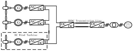
Figure 1.
Power collection and transmission grid connection methods for onshore wind farms.
In Figure 1, the DC/DC converter assumes a critical role in the voltage level conversion and energy distribution within the system. Its primary function is to match the DC voltage from the source side with the demand voltage on the load side. This enables efficient power transmission over long distances at high voltage levels, minimizing line losses. Moreover, the DC/DC converter plays a vital role in optimizing power output and isolating system faults in the wind power system. Employing precise voltage and current control, along with appropriate protection strategies, ensures the stable operation of the entire wind power system. Consequently, the design decisions regarding the DC/DC converter, particularly its topology structure and control strategy, significantly impact the performance and reliability of the overall wind power system.
2.2. DC/DC Converter Topology
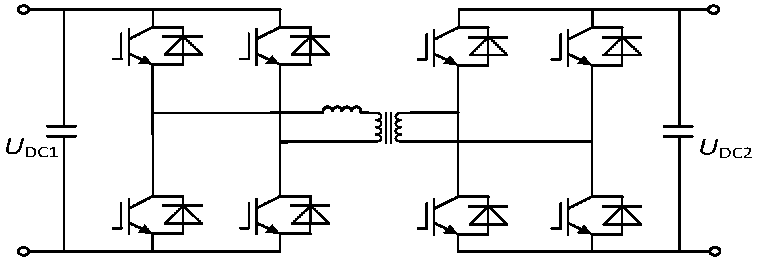
In general, the DC converter topology in Figure 1 exploits the structure of the dual active bridge (DAB), encompassing two full-bridge converters and an intermediate inductor. Thus, this structure enables the topology to achieve bidirectional power flow between the source and load, as illustrated in Figure 2.
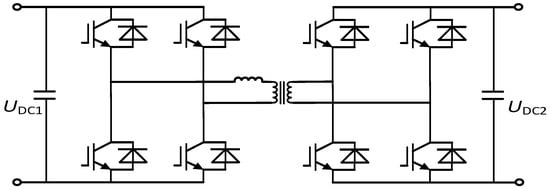
Figure 2.
DAB DC/DC converter.
In the comparative analysis of isolated multi-level DC/DC converter topologies within our study, the dual active bridge (DAB) converter stands out for its exceptional performance in high-voltage, high-power applications, a common requirement in wind power systems. The DAB converter exhibits superiority over conventional topologies like phase-shifted full bridges and push–pull converters for several compelling reasons.
Bidirectional power flow control: Unlike traditional converters that primarily offer unidirectional flow, the DAB converter supports efficient bidirectional power flow. This capability is crucial in wind power applications where power needs to be managed dynamically due to varying wind speeds, allowing for more effective energy utilization and storage.
Enhanced efficiency with low switching losses: The DAB converter is designed to operate with minimized switching losses, a key factor in achieving higher efficiency. This efficiency gain is due to its unique ability to adjust phase shifts between the input and output, reducing stress on components and thereby enhancing overall system longevity and reducing operational costs.
Simplified control strategy: The DAB converter utilizes a simpler control mechanism compared to more complex topologies. This simplicity results from its symmetrical structure, which allows for easier modulation and control of power flow, making it more suitable for systems where rapid and precise control is essential.
Improved fault tolerance and system robustness: The DAB converter’s design inherently provides better fault management capabilities. This advantage is particularly beneficial in wind power systems, where maintaining continuous operation and minimizing downtime is critical. The DAB’s ability to isolate faults and continue operation under partial failure conditions is a significant improvement over traditional designs.
Through detailed technical analysis and comparative studies, this paper highlights the DAB converter’s advantages in a full DC wind power system compared to other prevalent topologies. This analysis underscores the rationale for selecting the DAB converter as the focal technology of our research, demonstrating its potential to enhance system performance while reducing cost and complexity.
Under specific operational circumstances, the DAB converter has the capability to achieve zero-voltage switching, resulting in notable reductions in switching losses and enhanced system efficiency. Moreover, the DAB converter benefits from a wide range of well-established control strategies, such as phase-shift PWM control, allowing for favorable dynamic and steady-state performance. Nevertheless, when employed in high-voltage, high-power settings like onshore wind power full DC systems, the DAB converter encounters challenges such as limited voltage gain, intricate control requirements, and susceptibility to fluctuations in current and voltage.
2.3. Composite Modular DC/DC Converter Topology
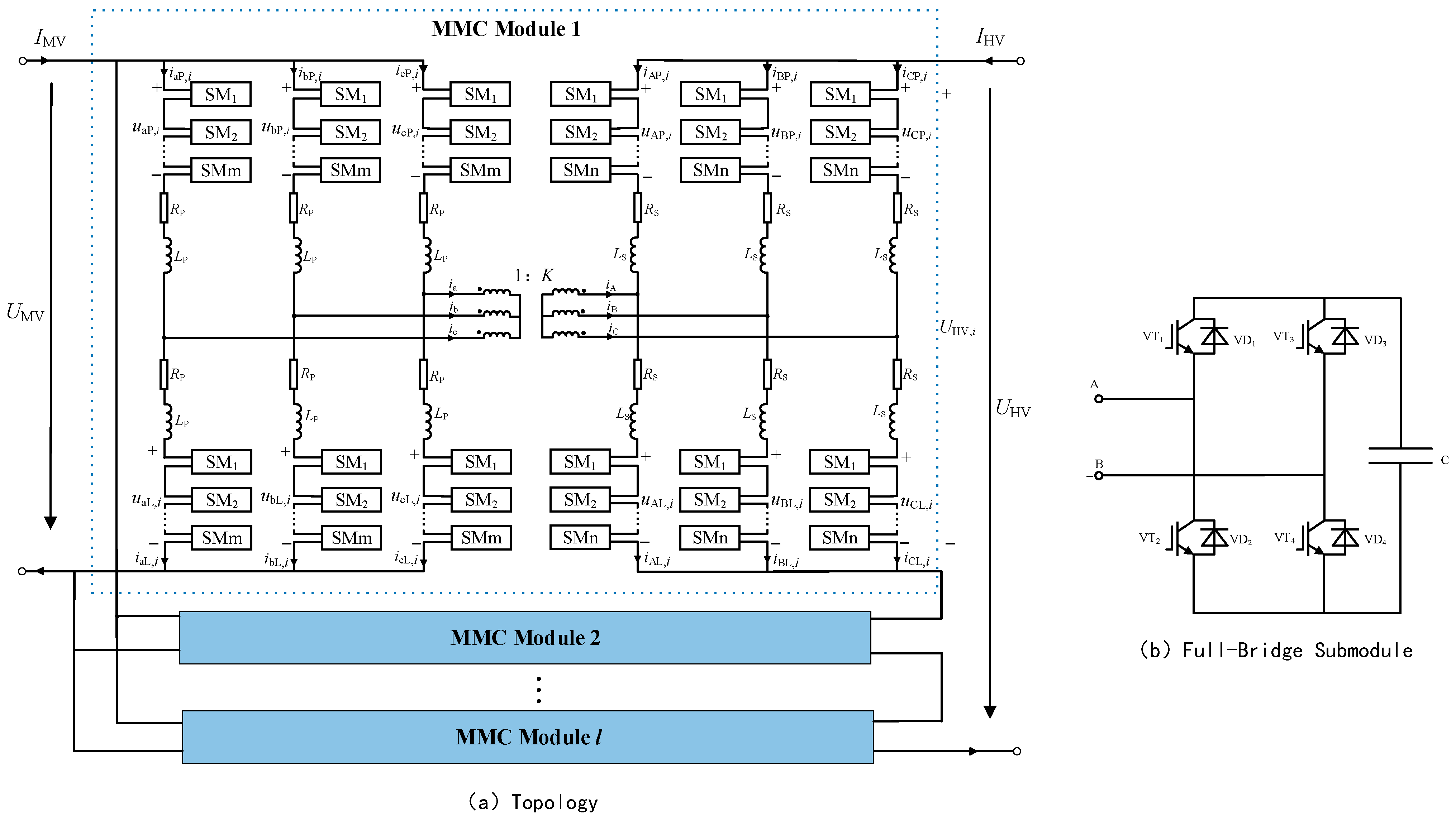
To address the limitations of the DAB structure, this study proposes a novel composite modular DC/DC converter topology based on MMC modules. The proposed topology, as illustrated in Figure 3, enhances flexibility by enabling the connection of multiple modules in series and parallel configurations, thereby accommodating diverse voltage and power levels. In comparison to the conventional DAB structure, this topology offers superior conversion efficiency and reduced control complexity and incorporates the fault isolation capability of the DAB, thereby bolstering system stability and safety. Furthermore, the performance of the converter is optimized through the implementation of control strategies, including circulating current suppression, nearest level approximation, and capacitor voltage sorting. These strategies improve the converter’s efficiency during steady-state operation.
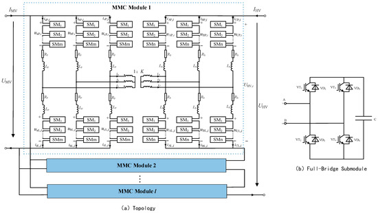
Figure 3.
Structure of high-voltage output DC/DC converter.
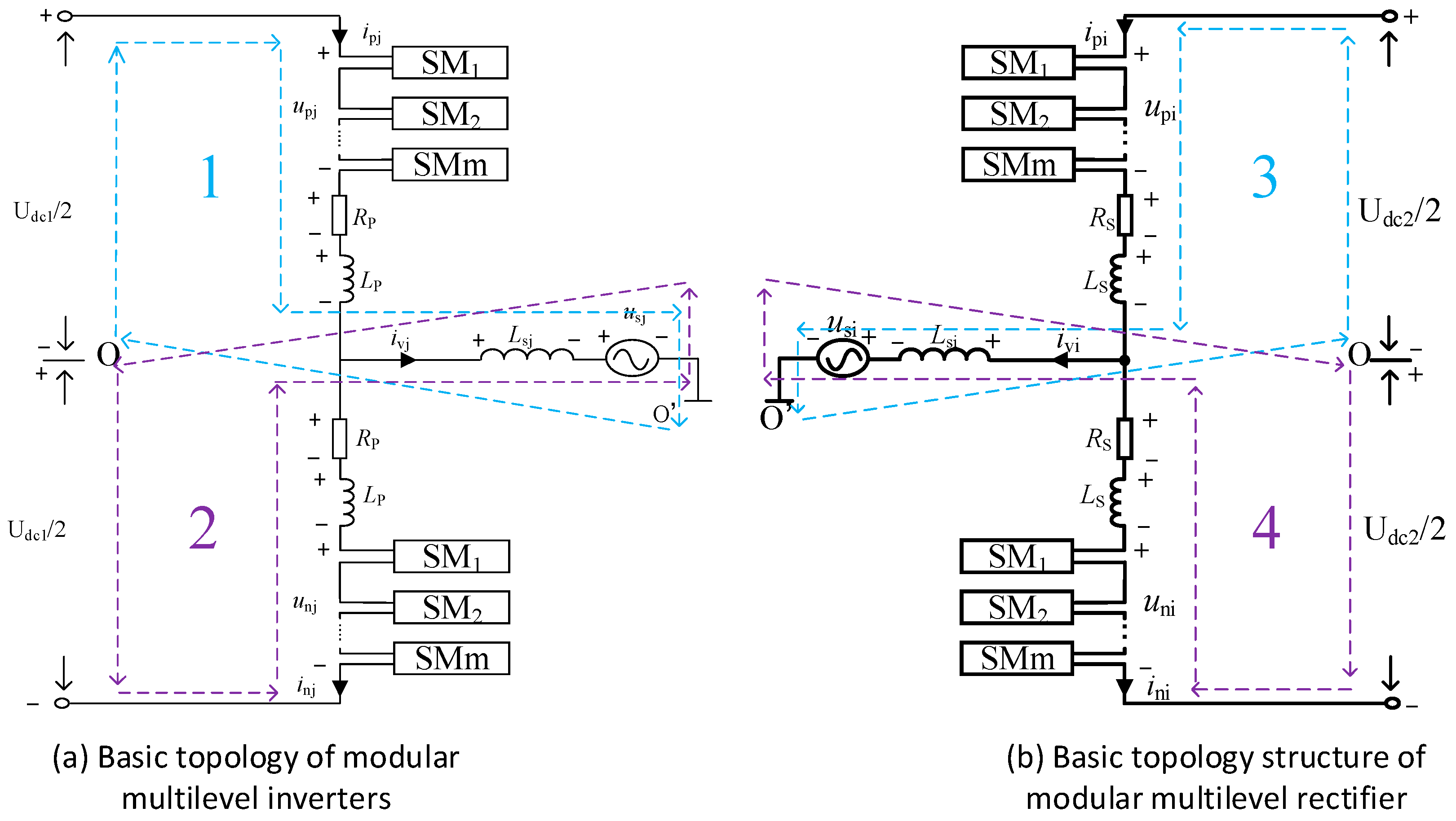
In Figure 3a, UMV and UHV denote the voltages of the medium- and high-voltage sides, respectively. IMV and IHV represent the currents of the medium- and high-voltage sides, respectively. UMV is the medium-voltage output voltage of module i. UHV, i is the high-voltage output voltage of module i (i = 1, 2, …, l). Specifically, UaP,i, UbP,i, UcP,i, UaL,i, UbL,i, UcL,i and iaP,i, ibP,i, icP,i, iaL,i, ibL,i, icL,i represent the arm voltages and arm currents of the inverter side of module i, respectively, where the subscripts P and L represent the upper and lower arms, and a, b, and c represent the three phases a, b, and c, respectively. K expresses the transformation ratio of the isolation transformer. ia, ib, ic, iA, iB, iC are the currents of the primary and secondary sides of the isolation transformer, respectively. LP and LS denote the arm inductances of the inverter and rectifier MMC, respectively.
In addition to the aforementioned design aspects, special attention has been paid to voltage equalization in high-voltage applications, especially considering the series-connected IGBTs. The necessity of implementing voltage equalization circuits in this topology is highlighted by the critical role these circuits play in maintaining the operational integrity and reliability of the IGBTs under high-voltage stresses.
Voltage equalization circuits are integrated into the MMC modules to ensure uniform voltage distribution across the series-connected IGBTs. This approach effectively prevents the occurrence of over-voltage conditions on individual IGBTs and ensures a balanced stress distribution across the entire array. The benefit of such a design is twofold: it not only enhances the system’s reliability by reducing the likelihood of component failure but also extends the operational lifespan of the IGBTs, which is pivotal in high-power applications.
Furthermore, the incorporation of these voltage equalization circuits significantly impacts the overall performance of the system. They contribute to maintaining system efficiency by preventing potential power losses associated with voltage imbalances and play a vital role in the thermal management of the system. The integration of these circuits thereby aligns with the stringent requirements of wind power systems, where system robustness and resilience to fluctuating inputs are paramount.
3. Mathematical Modeling of MMC
MMC has garnered significant interest in high-voltage direct current (HVDC) transmission systems owing to its remarkable performance and scalability resulting from its unique design. Nevertheless, achieving stable operation of the MMC necessitates a comprehensive understanding and precise control. In this regard, mathematical modeling assumes a crucial role as it equips us with the necessary tools to anticipate the dynamic behavior of the MMC. In the upcoming sections, we will establish a mathematical model for Figure 4, serving as the basis for subsequent analysis.
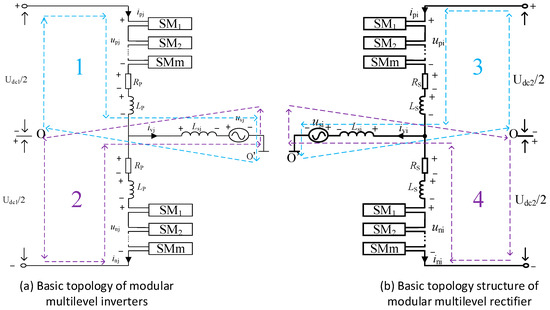
Figure 4.
Basic topology of modular multilevel converter.
MMC has aroused considerable interest in high-voltage direct current (HVDC) transmission due to its excellent performance and scalability brought by its design. However, ensuring the stable operation of MMC requires in-depth understanding and precise control. Here, mathematical modeling becomes the key, providing us with tools to predict the dynamic behavior of MMC. In the following sections, we will model Figure 4, laying the foundation for subsequent analysis.
The topology of inverters and rectifiers is fundamentally the same, thus the following analysis will focus solely on inverters.
From circuit 1, we have
Circuit 2 yields
By adding Equations (1) and (2), we obtain
Differential-mode voltage: .
Let , simplify (3) to obtain the differential-mode equation:
By subtracting Equations (1) and (2), we obtain the following function:
Set the circulating current as and the common-mode voltage as , then simplify (5) to derive the common-mode equation:
Transform the three-phase quantities to the dq axis and analyze the differential-mode equation of MMC (where the fundamental component of is 0):
After coordinate transformation, we obtain
Simplify Equation (8) to obtain
After Laplace transform and omission of (s), we obtain
Simplify to obtain
To further optimize the performance of the converter and improve its working efficiency under steady-state operation, control strategies are needed. Firstly, the analytical expression of the circulating current of MMC is investigated:
where represents the harmonic components above the third order, which can be ignored.
So (j = a, b, c) have
Since the phase sequence is negative, we need to perform a d−2q−2 transformation. The common-mode equation satisfies
After coordinate transformation, we obtain
Then, after Laplace transform, we obtain
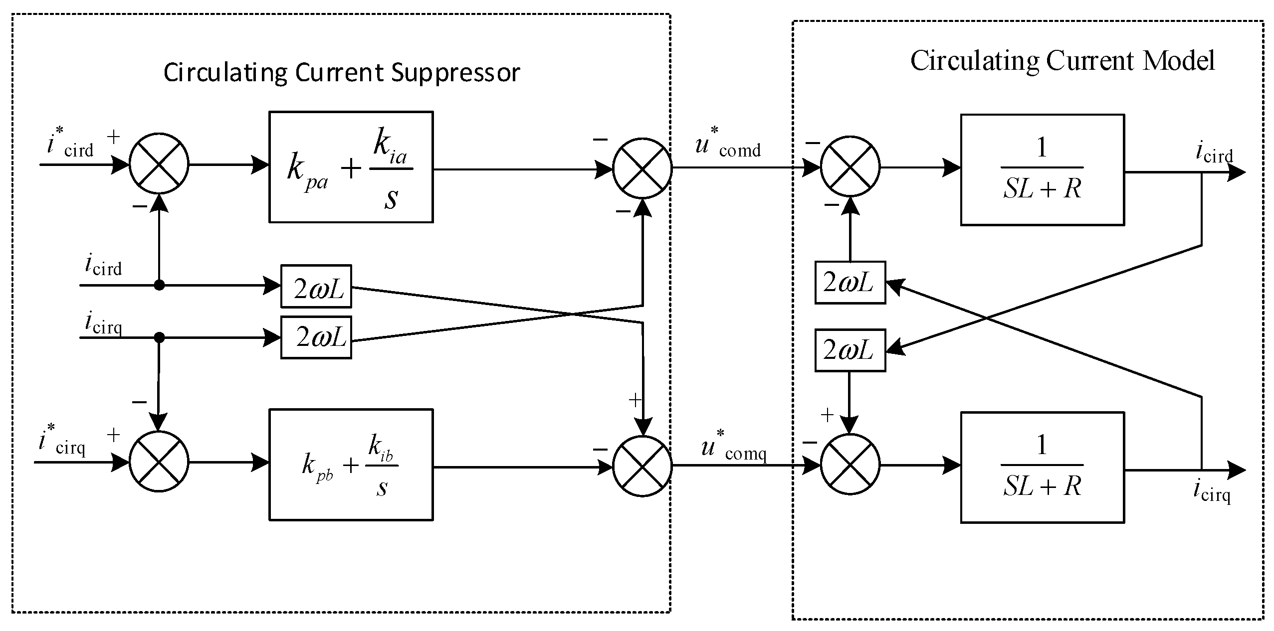
From Equation (16), we obtain the control block diagram of the MMC circulating current suppressor, as shown in Figure 8.
4. Control Strategy
To solve the phase-locking problem of grid voltage imbalance and reduce the sensitivity of the phase-locked loop to grid voltage harmonics, an improved SOGI (second-order generalized integrator) phase-locking technology is adopted, as shown in Figure 5.
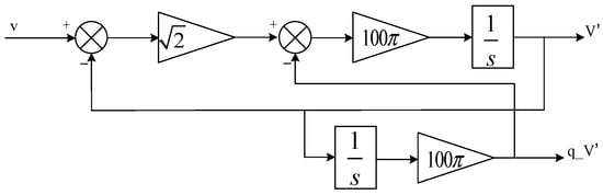
Figure 5.
SOGI phase lock.
4.1. Control Structure
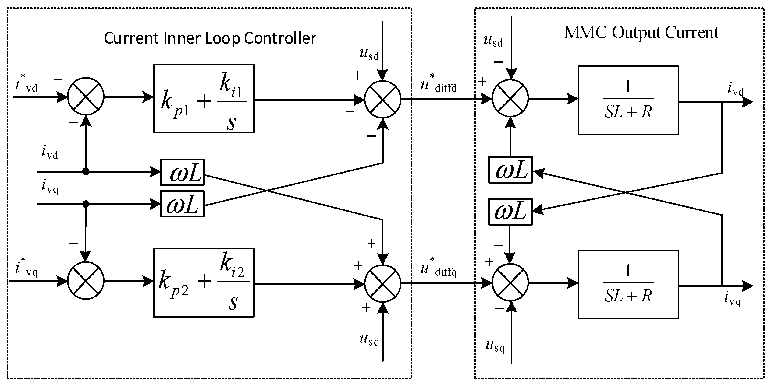
The inner loop current controller has two main functions. Firstly, by adjusting the differential-mode voltage (udiffd and udiffq) of the MMC upper and lower bridge arms, it realizes the fast tracking of the dq-axis current to the reference value. Secondly, by adjusting the common-mode voltage (ucomd and ucomq) of the MMC upper and lower bridge arms, it suppresses the internal circulating current to zero. The outer loop power controller calculates the dq-axis reference value (i*vd and i*vq) of the output current of the inner loop current controller based on reference values such as active power, reactive power, or DC voltage.
The inner loop current controller adopts a feedforward decoupling type, and the control block diagram is shown in Figure 6.
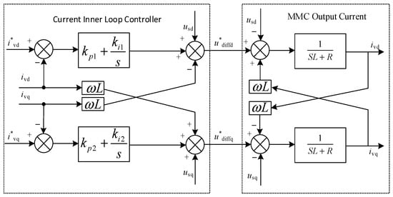
Figure 6.
Structure of the MMC inner loop controller.
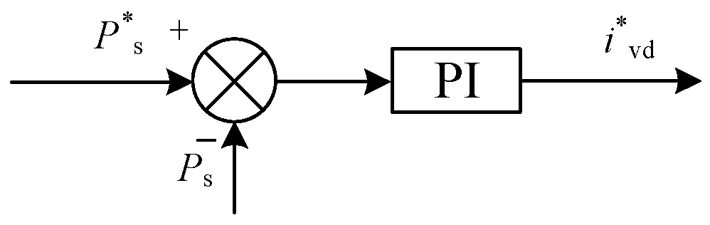
The power outer loop control of MMC is shown in Figure 7.

Figure 7.
MMC outer ring controller structure.
In the improvement of DC converter topology in the wind power full DC system, the inner loop controller plays a key role. To improve the dynamic stability of the system, a step module is introduced on the d-axis to control the grid-connected current and observe its impact on a dynamic steady state. At the same time, a dual closed-loop control strategy is adopted, where the inner loop control system is responsible for controlling the grid-connected current while the outer loop control system is responsible for controlling the grid-connected power.
4.2. Detection and Regulation of Circulating Current
First, define the circulating current:
Current expression for upper and lower bridge arms:
where “ihj” represents the circulating current component, including the DC component Idc/3, and the double-frequency content is the main target to be eliminated. In general, the circulating harmonic current is reflected in the bridge arm. The existence of a circulating current will cause distortion of the bridge arm current, which will cause adverse damage to the IGBT on the bridge arm. Therefore, it is imperative to take measures to suppress the circulating current.
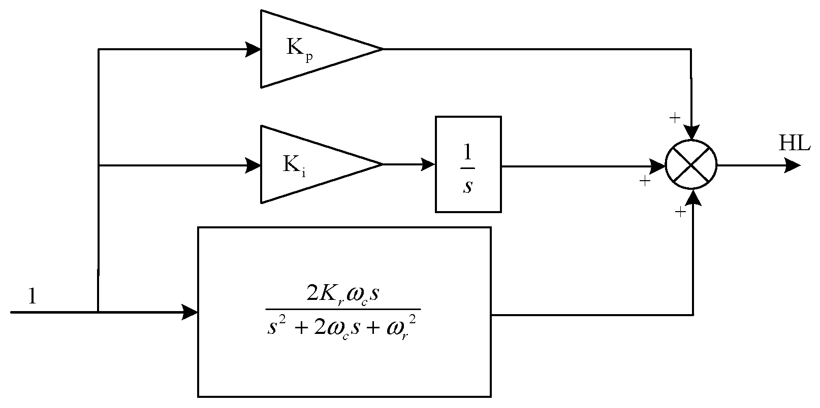
In accordance with the theoretical derivation of MMC, the internal circulating current of MMC primarily covers double-frequency components. Accordingly, the circulating current suppressor needs to suppress the double fundamental frequency part in the circulating current. For this, we can collect the circulating current signal and use a low-pass filter to extract the 100 Hz circulating current part from it. Subsequently, based on the comparison of the extracted circulating current part with the given value 0, the circulating current is suppressed by using the PIR (proportional-integral-resonant) suppression strategy. The structure of the circulating current suppressor is shown in Figure 8.
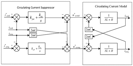
Figure 8.
Circulation suppressor.
The reason for using the PIR controller:
To effectively suppress the double-frequency components in the circulating current, we have employed a proportional-integral-resonant (PIR) control strategy. The PIR controller combines the techniques of proportional (P), integral (I), and resonant control to achieve higher control precision. Its proportional-integral (PI) component accurately tracks the DC component of the circulating current, ensuring zero steady-state error control. By proportionally adjusting the control signal and integrating the error, the PI part ensures precise control of the circulating current’s DC component.
Moreover, the PIR controller introduces quasi-resonant control, specifically designed to suppress the double-frequency circulating current. The quasi-resonant controller exhibits higher gain within a narrow bandwidth around the resonant angular frequency ωr, effectively mitigating the adverse effects of double-frequency circulating current. This design approach provides increased gain within the bandwidth around the resonant frequency, thereby enhancing the disturbance rejection capability.
The PIR control is a controller employed to enhance the performance of the DC converter topology in wind power full DC systems. The transfer function of PIR is
The PIR simulation model is illustrated in Figure 9.

Figure 9.
PIR controller model.
4.3. Optimal Level Selection Strategy
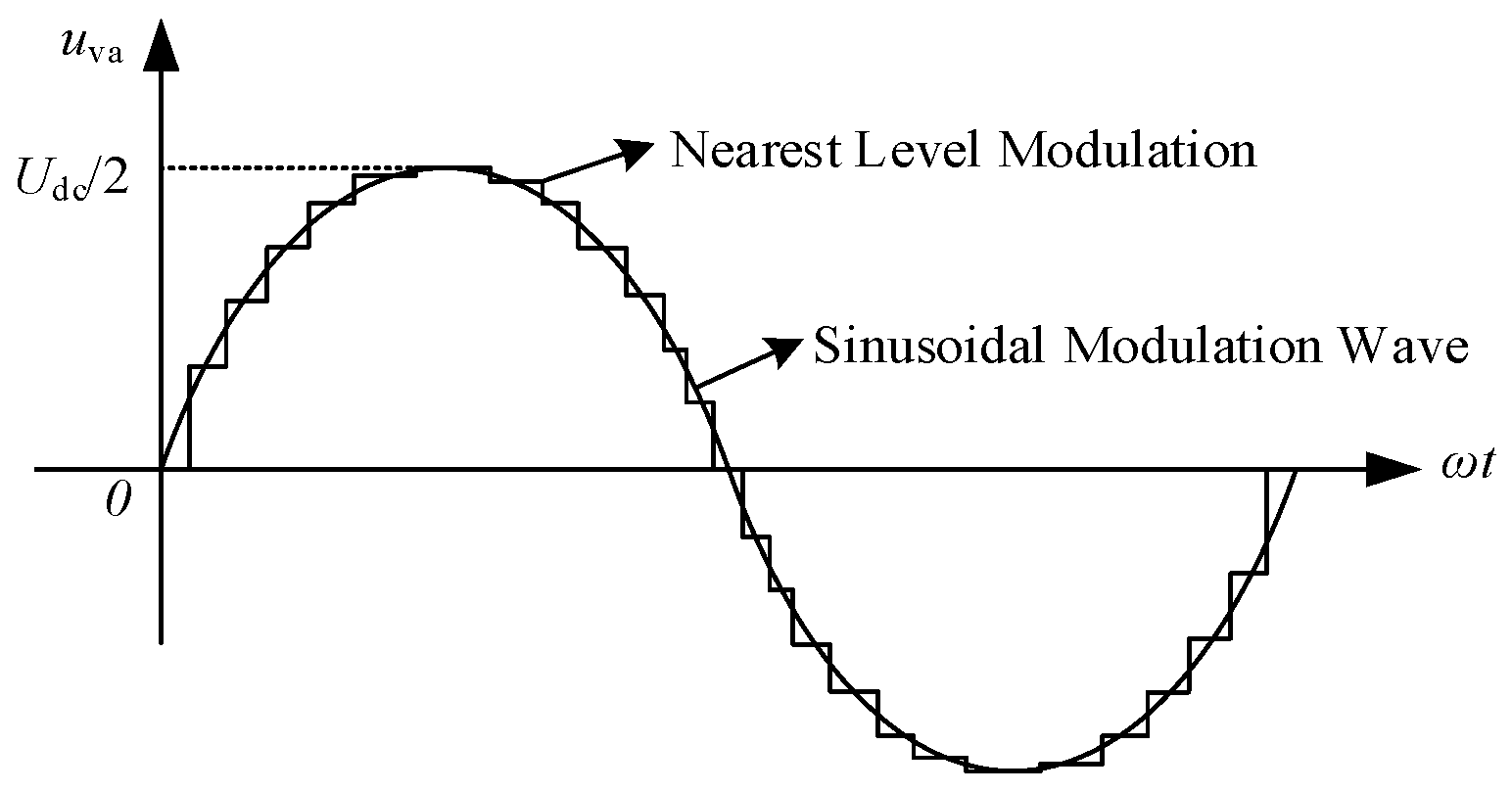
This study employs the nearest level approximation modulation strategy, which temporarily disregards the influence of the bridge arm reactor. The instantaneous value of the modulation wave at point vj (j = a, b, c) is represented by u*vj(t), while Uc denotes the time-averaged value of the DC voltage of the submodule. The parameter N (typically an even number) indicates the number of submodules present in both the upper and lower bridge arms. Consequently, N submodules are allocated to each phase unit. In the scenario where these N submodules are evenly distributed between the upper and lower bridge arms, the output voltage uvj of the phase unit is 0. Referring to Figure 10, as the instantaneous value of the modulation wave progressively increases from 0, the number of submodules required to be activated in the lower bridge arm of the phase unit gradually rises. Conversely, the number of submodules operating in the upper bridge arm proportionately decreases, resulting in an increase in the output voltage of the phase unit in tandem with the modulation wave’s ascent. Theoretically, the nonlinear modulation method ensures that the difference between the output voltage of the MMC and the modulation wave voltage remains within ±Uc/2. Therefore, at time t, the real-time expression for the number of submodules necessitating activation in the lower bridge arm can be calculated using the rounding function (denoted as “round”).

Figure 10.
Principle of nearest level approximation.
4.4. Optimization and Management of Capacitor Voltage
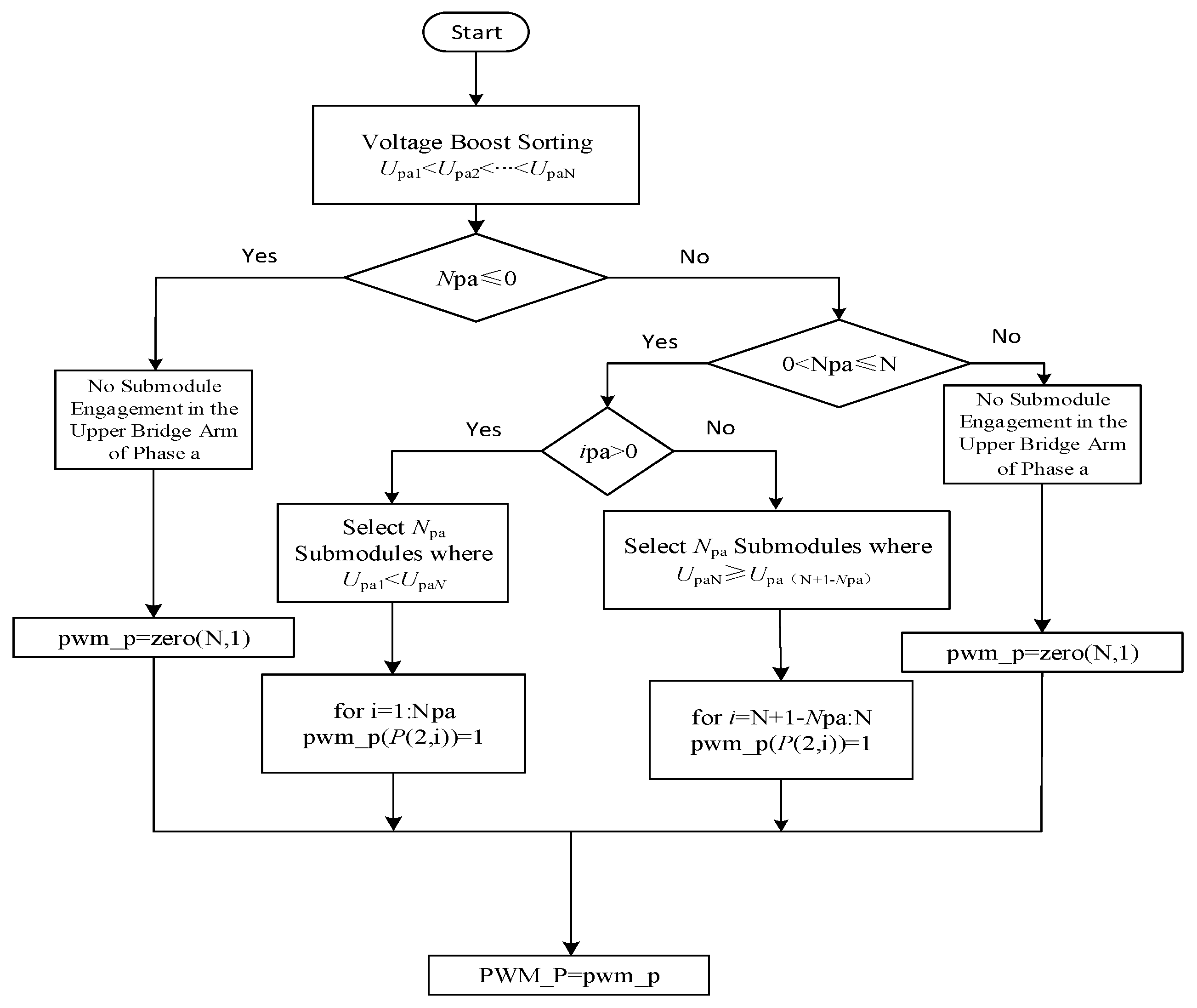
Following the application of the nearest level approximation modulation, it is necessary to achieve balance and sorting of the capacitor voltages. The process involves comparing the adjacent voltage values within the module capacitor voltage. If the preceding voltage value is smaller than the subsequent one, their positions are swapped. This guarantees that, after one iteration of the comparison process, the module with the highest voltage will ascend to the top of the sequence. Subsequently, the above process is repeated, excluding the elements at the end that have already been sorted. This iterative procedure continues until the entire voltage sequence is arranged in descending order. The sorting concept is illustrated in Figure 11.
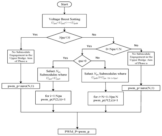
Figure 11.
Capacitor voltage sorting block diagram.
The sorting adopts bubble sorting. After the sorting is completed, the charging and discharging of the submodule capacitor are judged according to the direction of the bridge arm current. The input and cut-off are determined.
5. Simulation Verification
After the theoretical analysis and design, we conducted a series of simulation experiments to verify the effectiveness and performance of the proposed composite modular DC/DC converter topology and its control strategy, employing the MMC module and IPOS structure, as outlined in Figure 3. To validate the practicality and effectiveness of this design, one of the key experiments was conducted using a ±30 kV/±300 kV, 300 MW model constructed within the MATLAB/Simulink simulation environment. These simulation experiments are crucial, encompassing two key parts: circulating current analysis and DC output waveform inspection. The results from these experiments, especially the circulating current analysis, play a vital role in confirming the practical applicability and robustness of the design demonstrated in Figure 3. First, we will focus on the process and results of circulating current analysis.
5.1. Circulating Current Analysis
The circulating current comparison scheme is elucidated as follows. In the simulation process, the simulation time is set as t = 9 s, and the circulating current suppressor is put into operation at t = 4 s. By observing the circulating current waveform, bridge arm current waveform, and total harmonic distortion (THD) of the bridge arm current, the role of the circulating current suppressor is illustrated. The waveforms before and after inhibiting the circulation are depicted in Figure 12.
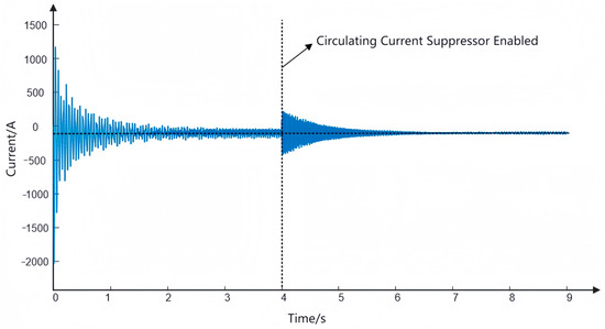
Figure 12.
The circulation before and after inhibition.
The observation results (Figure 12) indicate that the following conclusions can be drawn. Before inhibiting the circulation, a double-frequency component exists in the system’s circulating current, resulting in more harmonic components in the circulating current. Nevertheless, when the simulation time reaches t = 4 s, the circulating current suppressor starts to work. The PI controller plays a certain role: making the circulating current suppressed. In the suppression process, the double-frequency component in the circulating current is effectively suppressed, making the circulating current waveform gradually tend to a stable value, namely Idc/3, suggesting that the circulating current suppressor of the PI controller has a good suppression effect.
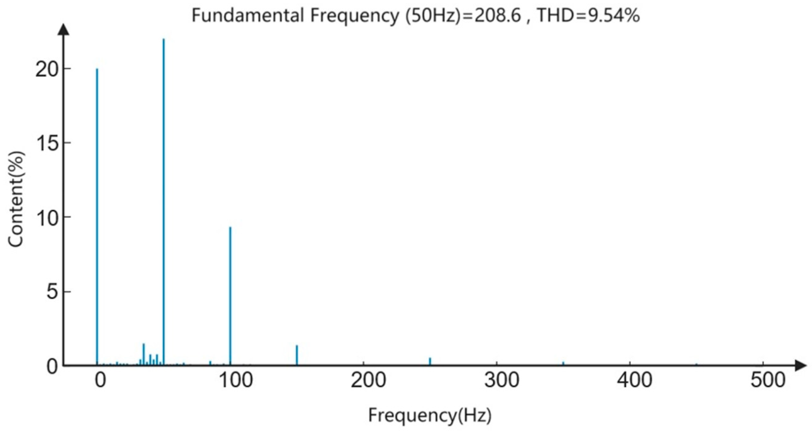
The circulating current is primarily generated by the MMC internally, pronouncedly affecting the bridge arm current. By comparing the waveform and THD of the bridge arm current before and after inhibiting the circulation, we can clearly observe the effect of circulating current suppression. The bridge arm current waveform diagram before inhibiting the circulation is depicted in Figure 13.
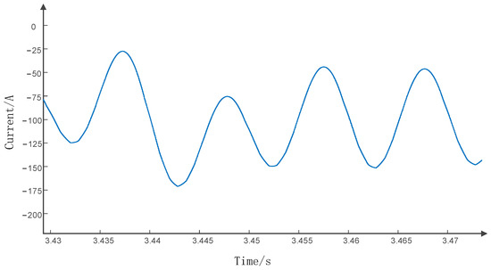
Figure 13.
Circulation suppresses the front arm current.
Before circulating current suppression, it can be clearly observed that the bridge arm current is distorted, which will have a negative impact on the bridge arm device. The opening of the bridge arm current valley is large, and the opening of the peak is small. Taking t = 3 s, 20 cycles as an example, through FFT analysis, it can be seen that the THD of the bridge arm current is 9.54%, and the THD of the bridge arm current is shown in Figure 14.
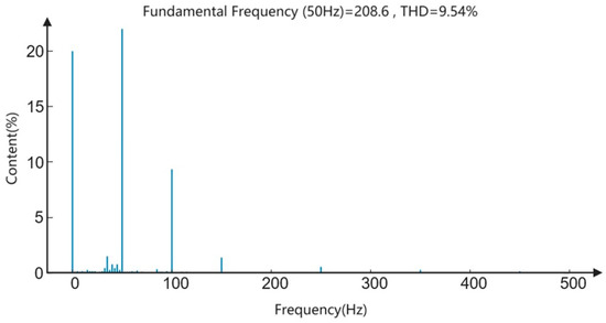
Figure 14.
Circulation suppresses the front axle arm current THD.
As depicted in Figure 14, the 100 Hz part is the double-frequency component, and it can be clearly seen that the double-frequency component in the circulating current exceeds 9%. This means that there is a large double-frequency harmonic component in the circulating current, which needs to be suppressed. After introducing the circulating current suppressor, the bridge arm current is improved, and the bridge arm current waveform after circulation suppression is shown in Figure 15.
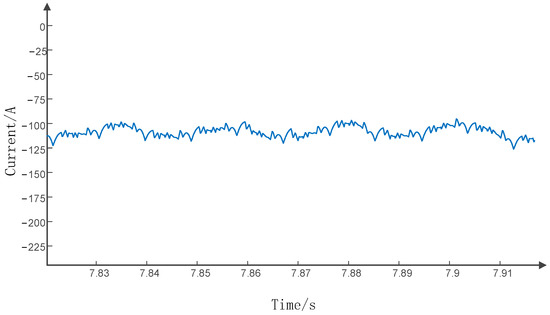
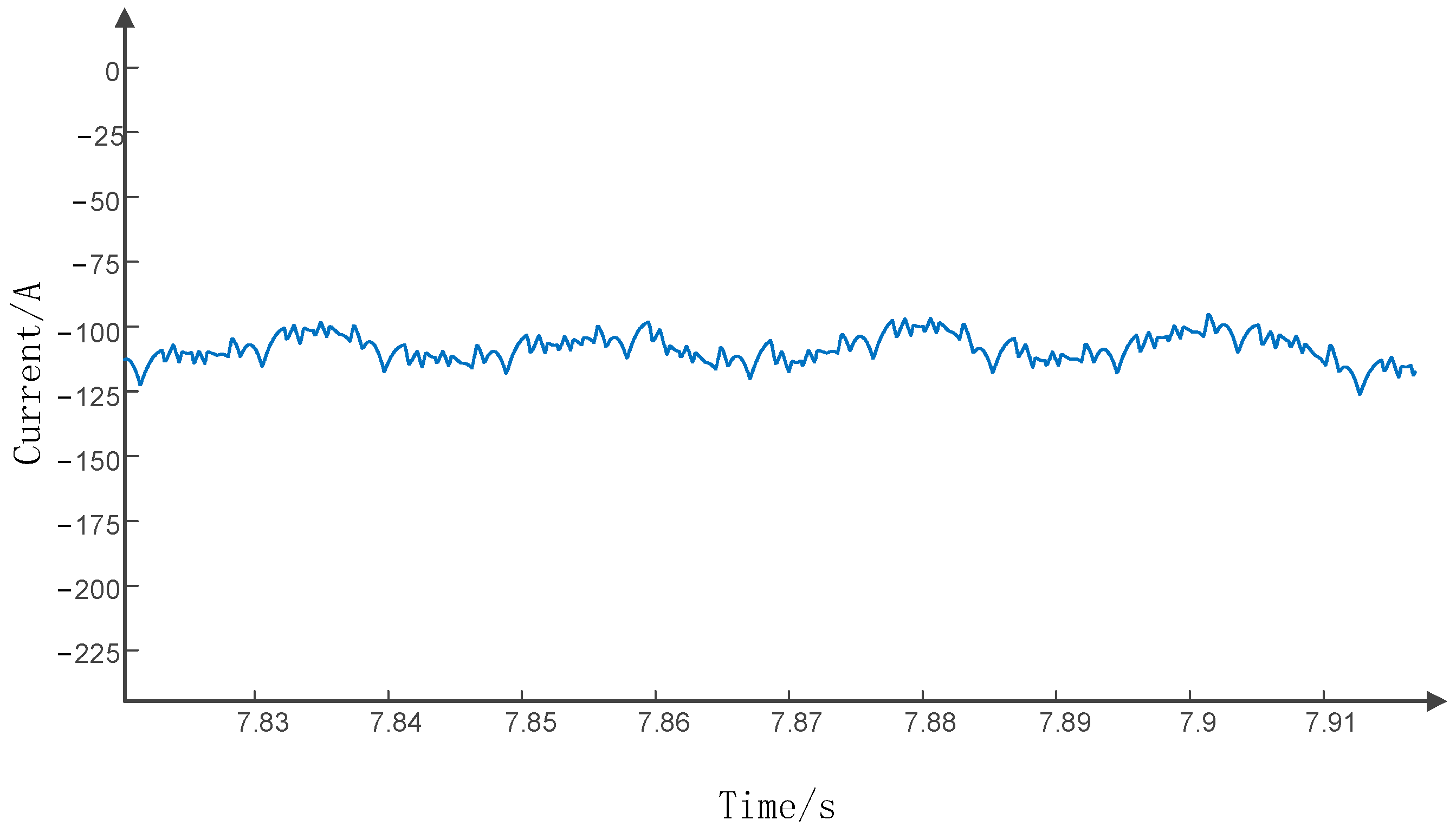
Figure 15.
Circulation suppresses rear axle arm current.
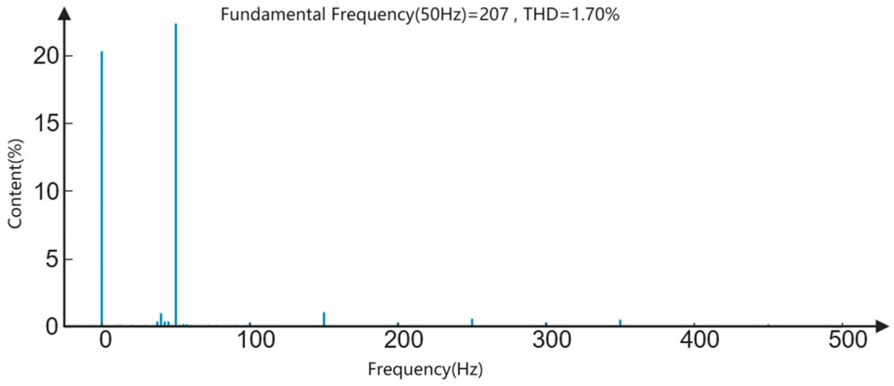
After circulation suppresses, it can be clearly observed that the waveform of the bridge arm current is improved. Taking t = 7 s, 20 cycles as an example, through FFT analysis, the THD of the bridge arm current is 1.70%, and the THD of the bridge arm current is shown in Figure 16.
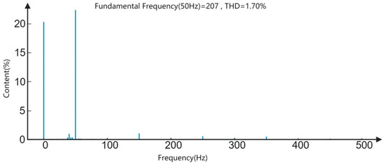
Figure 16.
Circulation suppresses rear axle arm current THD.
As depicted in Figure 16, the 100 Hz part represents the double-frequency component. This component is effectively suppressed, below 2%, suggesting that the internal circulating current has been significantly improved, confirming the effectiveness of the PI circulating current suppressor.
In this chapter, we present the simulation results that validate the effectiveness and performance of the proposed composite modular DC/DC converter topology and control strategies. These simulations are grounded in the mathematical framework established in earlier sections, particularly relying on Equations (1)–(20), which model the dynamic behavior and control mechanisms of the system.
The simulation analysis comprises two main parts: circulating current analysis and DC output waveform inspection. These simulations are executed by employing the mathematical models detailed previously, ensuring a cohesive and consistent approach in our research. As such, we directly correlate the theoretical foundations with the practical outcomes, demonstrating the practical applicability and robustness of our proposed solutions under various operational scenarios.
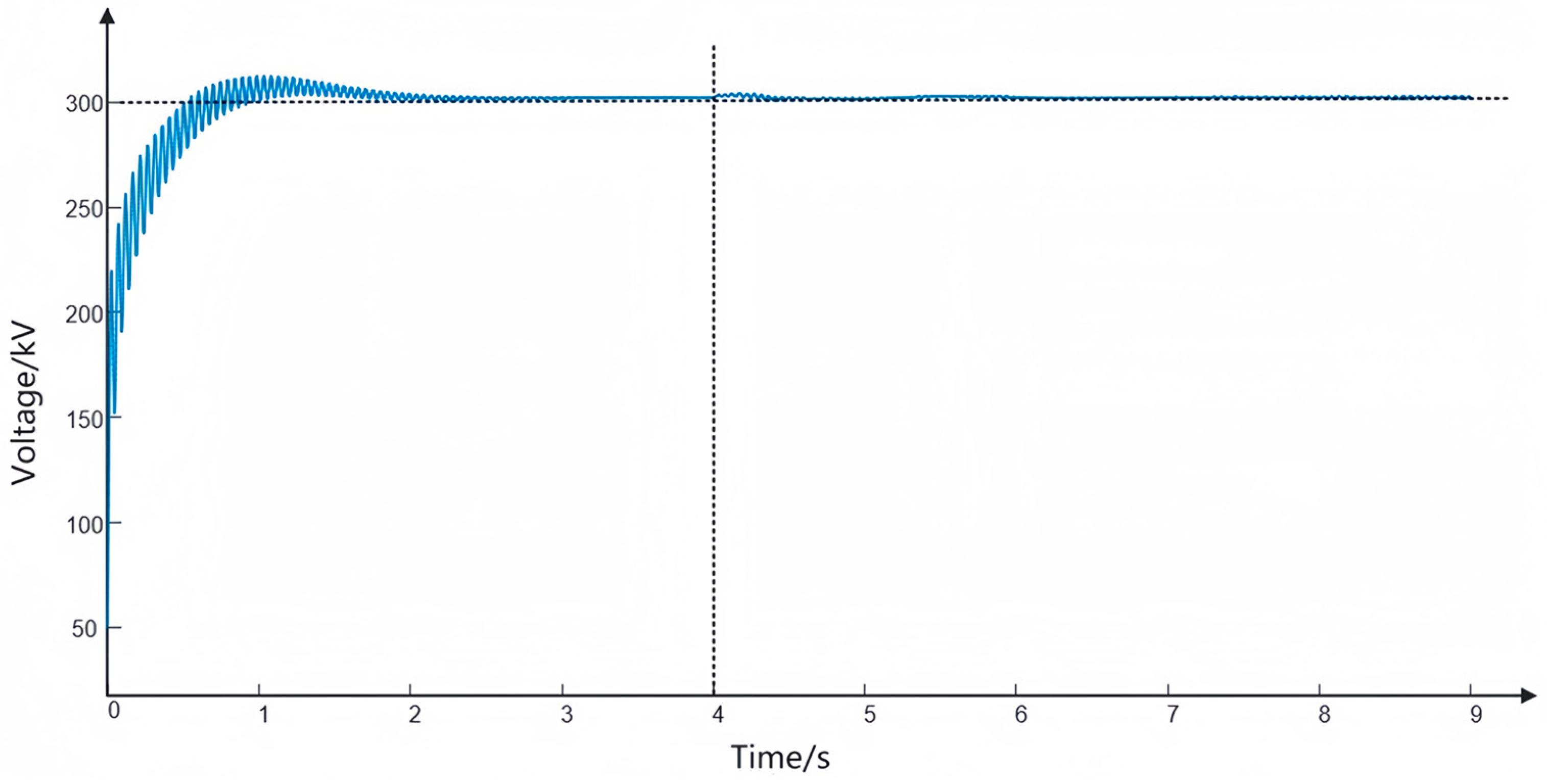
5.2. DC Output Waveform
The primary objective of the MMC rectifier is to perform AC-to-DC voltage conversion, thereby fulfilling the rectification function. The waveform of its DC output voltage is illustrated in Figure 17. Based on an analysis of Figure 17, the following conclusions can be derived. Prior to t = 2 s, the system is in an adjustment state, exhibiting an overshoot. However, the peak value does not surpass 315 kV. Subsequently, after the system undergoes adjustment, it stabilizes at the designated DC voltage value, specifically tracking 300 kV. This observation highlights the MMC rectifier’s role in the rectification process. Moreover, the MMC rectifier effectively tracks the predetermined value, maintains stability in the steady state, and exhibits favorable quality in terms of the DC output waveform.

Figure 17.
Voltage output waveform.
5.3. Comparison of the Power of the System
By measuring the power, the waveform of the output power on the rectifier side can be observed, as illustrated in Figure 18.
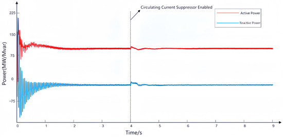
Figure 18.
Power waveform.
According to the observation results of Figure 18, the stability of the output power of the rectifier side can be obtained. The active power is 100 MW, and the reactive power is almost 0 Var. This indicates that the power factor of the grid side input is relatively large, mainly providing active power, and the active power is stable, with good waveform quality.
6. Conclusions
The objective of this study is to enhance the DC converter topology in onshore wind power full DC systems, catering to the technical demands of high-capacity, high-voltage DC/DC converters. In light of this context, a composite modular DC/DC converter topology based on MMC module IPOS is proposed, leading to the following key findings:
The composite modular converter structure, based on the MMC module, offers enhanced flexibility, enabling its adaptability to various voltage and power levels. It is particularly suitable for high-power and high-voltage applications, such as onshore wind power delivery. Moreover, this structure reduces the rated capacity requirements of the intermediate frequency transformer and mitigates the insulation demands of primary and secondary voltages. Consequently, it alleviates engineering complexities associated with system implementation.
To ensure the stable operation of this novel structure, a series of control strategies are suggested in this study, including circulation inhibition, nearest level approximation, and capacitor voltage sorting. The implementation of these control strategies not only optimizes the converter’s performance but also enhances its effectiveness during steady-state operation.
In conclusion, the composite modular DC/DC converter topology, based on the MMC module and IPOS structure, proposed in this study exhibits promising prospects for practical applications and research advancements. However, it should be noted that the research is still in its preliminary stage, and no actual experimental research or verification has been conducted yet. Furthermore, the current investigation primarily focuses on control strategies for steady-state operation, while further research is required to explore protection measures for system or converter internal faults in greater depth.
Author Contributions
Methodology, W.H.; Validation, F.L. All authors have read and agreed to the published version of the manuscript.
Funding
This research was funded by the National Key Research and Development Program of China under Grant 2021YFB1507000.
Data Availability Statement
Data is contained within the article.
Conflicts of Interest
The authors declare no conflict of interest.
References
- Sankaranarayanan, V.; Shirazi, M.; Gao, Y.; Ghosh, A.; Erickson, R.W.; Maksimovic, D. Controller Hardware-in-the-Loop Validation of a Modular Control Architecture for a Composite DC-DC Converter. In Proceedings of the 2019 20th Workshop on Control and Modeling for Power Electronics (COMPEL), Toronto, ON, Canada, 16–19 June 2019; pp. 1–7. [Google Scholar] [CrossRef]
- Akter, K.; Motakabber, S.M.A.; Alam, A.H.M.Z.; Yusoff, S.H.B. A New High Step-Up DC-DC Converter for Photovoltaic Application: Switch Inductor Cell Combined with Voltage Doubler Circuit. In Proceedings of the 2022 International Conference on Recent Progresses in Science, Engineering and Technology (ICRPSET), Rajshahi, Bangladesh, 26–27 December 2022; pp. 1–5. [Google Scholar] [CrossRef]
- Mahdavi, M.; Jurado, F.; Schmitt, K.; Chamana, M. Electricity Generation from Cow Manure Compared to Wind and Photovoltaic Electric Power Considering Load Uncertainty and Renewable Generation Variability. IEEE Trans. Ind. Appl. 2022. early access. [Google Scholar] [CrossRef]
- Mahdavi, M.; Jurado, F.; Ramos, R.A.V.; Awaafo, A. Hybrid biomass, solar and wind electricity generation in rural areas of Fez-Meknes region in Morocco considering water consumption of animals and anaerobic digester. Appl. Energy 2023, 343, 121253. [Google Scholar]
- Bahirat, H.J.; Mork, B.A.; Høidalen, H.K. Comparison of wind farm topologies for offshore applications. In Proceedings of the IEEE Power and Energy Society General Meeting, San Diego, CA, USA, 22–26 July 2012. [Google Scholar]
- Cheng, C.-A.; Lee, C.-M.; Chang, E.-C.; Hou, S.-H.; Lan, L.-F.; Lin, C.-K. A Novel Integrated Electronic Lighting Driver Circuit for Supplying an LED Projection Lamp with High Power Factor and Soft Switching Characteristics. Electronics 2023, 12, 4642. [Google Scholar] [CrossRef]
- Wang, G.; Wen, H. Design and optimization of modular multilevel DC transformer. In Proceedings of the 2021 IEEE 16th Conference on Industrial Electronics and Applications (ICIEA), Chengdu, China, 1–4 August 2021; pp. 643–648. [Google Scholar] [CrossRef]
- Rosas-Caro, J.C.; Valdez-Resendiz, J.E.; Escobar, G.; Beltran-Carbajal, F. A Multilevel Boost Converter with Reduced Inductor Current. Electronics 2023, 12, 4585. [Google Scholar] [CrossRef]
- Sikorski, A.; Falkowski, P.; Korzeniewski, M. Comparison of Two Power Converter Topologies in Wind Turbine System. Energies 2021, 14, 6574. [Google Scholar] [CrossRef]
- Bahirat, H.J.; Kjølle, G.H.; Mork, B.A.; Høidalen, H.K. Reliability assessment of DC wind farms. In Proceedings of the IEEE Power and Energy Society General Meeting, San Diego, CA, USA, 22–26 July 2012. [Google Scholar]
- Tekin, H.; Setrekli, G.; Murtulu, E.; Karşıyaka, H.; Ertekin, D. A Proposed Single-Input Multi-Output Battery-Connected DC–DC Buck–Boost Converter for Automotive Applications. Electronics 2023, 12, 4381. [Google Scholar] [CrossRef]
- Huang, K.; Xiang, W.; Xu, L.; Wang, Y. Hybrid AC/DC hub for integrating onshore wind power and interconnecting onshore and offshore DC networks. IET Renew. Power Gener. 2020, 14, 1738–1745. [Google Scholar] [CrossRef]
- Saadi, R.; Hammoudi, M.Y.; Salah, O.; Laadjal, K.; Cardoso, A.J.M. A Two-Degree-of-Freedom PID Integral Super-Twisting Controller Based on Atom Search Optimizer Applied to DC-DC Interleaved Converters for Fuel Cell Applications. Electronics 2023, 12, 4113. [Google Scholar] [CrossRef]
- Abeynayake, G.; Li, G.; Joseph, T.; Liang, J.; Ming, W. Reliability and cost-oriented analysis, comparison and selection of multi-level MVDC converters. IEEE Trans. Power Deliv. 2021, 36, 3945–3955. [Google Scholar] [CrossRef]
- Wan, D.; Zhou, Q.; Duan, X.; Zhu, J.; Li, J.; Zhou, H. A High-Power Density DC Converter for Medium-Voltage DC Distribution Networks. Electronics 2023, 12, 3975. [Google Scholar] [CrossRef]
- Lakshmanan, P.; Liang, J.; Jenkins, N. Assessment of collection systems for HVDC connected offshore wind farms. Electr. Power Syst. Res. 2015, 129, 75–82. [Google Scholar] [CrossRef]
- Deng, F.; Chen, Z. Control of Improved Full-Bridge Three-Level DC/DC Converter for Wind Turbines in a DC Grid. IEEE Trans. Power Electron. 2013, 28, 314–324. [Google Scholar] [CrossRef]
- Muppalla, N.R.K.; Rao, Y.S.; Sanam, J. Design of Compensator for High Gain DC-DC Converter. In Proceedings of the 2021 International Conference on Sustainable Energy and Future Electric Transportation (SEFET), Hyderabad, India, 23–21 January 2021; pp. 1–5. [Google Scholar] [CrossRef]
- Nishikata, S.; Tatsuta, F. A new interconnecting method for wind turbine/generators in a wind farm and basic performances of the integrated system. IEEE Trans. Ind. Electron. 2010, 57, 468–475. [Google Scholar]
- Barker, C.D.; Davidson, C.C.; Trainer, D.R.; Whitehouse, R. Requirements of DC-DC converters to facilitate large DC grids. In Proceedings of the CIGRE, SC B4 HVDC and Power Electronics, Paris, France, 26–31 August 2012. [Google Scholar]
- Ferreira, J.A. The multilevel modular DC converter. IEEE Trans. Power Electron. 2013, 28, 4460–4465. [Google Scholar]
- Xu, Z. Flexible DC Power Transmission Systems, 2nd ed.; Mechanical Industry Press: South Norwalk, CT, USA, 2018. [Google Scholar]
- Li, B.B.; Liu, J.Y.; Wang, Z.Y.; Zhang, S.; Xu, D. Modular high-power DC-DC converter for MVDC renewable energy collection systems. IEEE Trans. Ind. Electron. 2021, 68, 5875–5886. [Google Scholar] [CrossRef]
- Rufer, A. High-Power high-voltage isolated DC-DC converters using an NPC balanced capacitive divider. In Proceedings of the 2015 17th European Conference on Power Electronics and Applications (EPE’15 ECCE-Europe), Geneva, Switzerland, 8–10 September 2015; pp. 1–10. [Google Scholar] [CrossRef]
- Pape, M.; Kazerani, M. A Generic Power Converter Sizing Framework for Series-Connected DC Offshore Wind Farms. IEEE Trans. Power Electron. 2022, 37, 2307–2320. [Google Scholar] [CrossRef]


Disclaimer/Publisher’s Note: The statements, opinions and data contained in all publications are solely those of the individual author(s) and contributor(s) and not of MDPI and/or the editor(s). MDPI and/or the editor(s) disclaim responsibility for any injury to people or property resulting from any ideas, methods, instructions or products referred to in the content. |
© 2024 by the authors. Licensee MDPI, Basel, Switzerland. This article is an open access article distributed under the terms and conditions of the Creative Commons Attribution (CC BY) license (https://creativecommons.org/licenses/by/4.0/).