Abstract
Development of present-day antenna systems is an intricate and multi-step process requiring, among others, meticulous tuning of designable (mainly geometry) parameters. Concerning the latter, the most reliable approach is rigorous numerical optimization, which tends to be resource-intensive in terms of computing due to involving full-wave electromagnetic (EM) simulations. The cost-related issues are particularly pronounced whenever global optimization is necessary, typically carried out using nature-inspired algorithms. Although capable of escaping from local optima, population-based algorithms exhibit poor computational efficiency, to the extent of being hardly feasible when directly handling EM simulation models. A popular mitigation approach involves surrogate modeling techniques, facilitating the search process by replacing costly EM analyses with a fast metamodel. Yet, surrogate-assisted procedures feature complex implementations, and their range of applicability is limited in terms of design space dimensionality that can be efficiently handled. Rendering reliable surrogates is additionally encumbered by highly nonlinear antenna characteristics. This paper investigates potential benefits of employing problem-relevant knowledge in the form of response features into nature-inspired antenna optimization. As demonstrated in the recent literature, re-formulating the design task with the use of appropriately selected characteristic locations of the antenna responses permits flattening the functional landscape of the objective function, leading to faster convergence of optimization procedures. Here, we apply this concept to nature-inspired global optimization of multi-band antenna structures, and demonstrate its relevance, both in terms of accelerating the search process but also improving its reliability. The advantages of feature-based nature-inspired optimization are corroborated through comprehensive (based on three antenna structures) comparisons with a population-based search involving conventional (e.g., minimax) design problem formulation.
1. Introduction
Modern antenna systems have to satisfy stringent performance specifications and multi-functionality demands [1], implied by the requirements stemming from newly-developed areas such as the Internet of Things (IoT) [2], wireless communications [3] including 5G [4,5], body area networks [6], microwave imaging [7], satellite communications [8], radar [9], or remote sensing [10]. Specific functionalities required for these and other applications include broadband [11] and multi-band functioning [12], multiple-input–multiple-output (MIMO) operation [13], circular polarization [14], beam scanning [15], reconfigurability [16,17], high directivity [18], polarization/pattern diversity [19], etc. Apart from boosting electrical and field parameters, miniaturization demands also become commonplace, being especially important for mobile communications [20], implantable/wearable devices [21], and IoT [22]. This leads to additional design challenges, as reduction of antenna size is detrimental to electrical performance [23,24]. The latter enforces seeking trade-off solutions that satisfy constraints imposed on physical dimensions while ensuring sufficient functionality. Design of high-performance and multi-functional antennas is associated with the development of structures containing defected ground structures [25], stubs [26], slots [27], shorting pins [28], substrate-integrated waveguide (SIW) [29], or metamaterial components [30,31], often implemented as multi-layer geometries [32,33]. Accurate characterization of topologically complex devices requires full-wave electromagnetic (EM) analysis, which has been commonly involved at virtually all design stages, such as topology evolution [34], parametric studies [35], and design closure [36,37].
Given the antenna geometry, careful adjustment of geometry parameters is the single most important step towards improving electrical performance of the device. Traditionally, this has been commonly realized through parameter sweeping guided by engineering know-how; however, this approach is no longer adequate given the complexity of contemporary antennas, a typically large number of variables, as well as several objectives and constraints that have to be simultaneously handled. Instead, rigorous numerical optimization is preferred [38,39]. Although a large number of optimization techniques are available, a common issue is high computational cost of EM-driven design, which may prove problematic even when carrying out local search using gradient-based [40] or derivative-free methods [41]. On the other hand, the need for global optimization has been growing as well [42]. It is necessary for multimodal tasks (i.e., whenever the presence of multiple local optima is expected), such as synthesis of antenna array patterns [43], design of metamaterials (e.g., broadband frequency selective surfaces or coding metasurfaces [44]), re-design of antennas over wide ranges of operating frequencies (especially in the case of multi-band structures), but also whenever an initial design of a decent quality is not easily obtainable. The latter situation is especially pertinent to miniaturized structures [45], or antennas implementing additional functionalities [46,47]. Understandably, global optimization incurs significantly higher CPU expenses as compared to local search.
Population-based nature-inspired algorithms are currently the most popular approaches to global optimization [48,49,50]. Although they have a relatively long history, dating back to late 1960s (evolutionary strategies [51]), their broader utilization started in 1980s with the development of genetic algorithms [52], followed by evolutionary methods [53], genetic programming [54], and ant systems [55]. Particle swarm optimizers (PSO) [56] and differential evolution (DE) [57] were the next significant milestones, especially in terms of continuous optimization. From the early 2000s, nature-inspired methods virtually dominated global searches, and new algorithms have been emerging ever since (e.g., harmony search [58], firefly algorithm [59], grey wolf optimization [60], invasive weed optimization [61], and others [62,63,64]). Despite this variety, the actual differences between the algorithms, especially the recent ones, are rather minor. Nature-inspired procedures process the sets (population [53], pack [60], swarm [56], etc.) of prospective solutions (individuals, agents, particles, etc.) to a problem at hand. The candidate solutions exchange information and generate new ones by means of exploratory [65] and exploitative operators [66], which allows for finding the most promising parameter space regions but also escaping from local optima. The latter arguably results in global search capability [67]. Also, the algorithms of this class are easy to deploy. Still, population-based operation results in inferior computational efficiency, as a typical merit function call required by a single algorithm run may be as high as many hundreds or even thousands. Clearly, such costs may be prohibitive from the perspective of EM-driven design.
Poor computational efficiency hinders utilization of population-based methods for antenna design. In practice, their straightforward application is only possible when using low-cost representations (e.g., pattern optimization with analytical array factor models [68], dedicated solvers with evaluation times at the level of seconds), or parallelization, the latter requiring sufficient computational resources and licensing. An alternative is utilization of surrogate modeling techniques [69], more often than not data-driven (kriging [70], Gaussian process regression [71], neural networks [72]), often combined with sequential sampling methods [73]. In the latter, an iterative refinement of the surrogate is carried out using EM-generated data amassed during the optimization process [74]. Within these methodologies, fast metamodels are employed instead of expensive EM simulations to make predictions about potentially better designs [75]. The incorporation of surrogate models constitutes at present the most popular approach to nature-inspired optimization of heavy-cost simulation models. Its limitation, especially when antenna design is considered, is the curse of dimensionality and nonlinearity of antenna characteristics, both impeding a rendition of reliable surrogates at reasonable costs. In practice, conventional modeling methods may handle structures featuring a few variables [76,77]. This difficulty can be somewhat alleviated by means of domain-confined surrogates [78], or utilization of variable-resolution EM models [79]. Recently, new surrogate-assisted techniques allowing for global design optimization of antenna [80] and microwave structures [81] have been proposed, where the challenges stemming from the curse of dimensionality have been handled by the employment of a self-adaptive Gaussian process as the underlying surrogate model.
This work investigates the possibility of mitigating the challenges of EM-driven nature-inspired antenna optimization by making use of the problem-specific knowledge expressed as response features [82]. The response feature approach has been developed to speed up local optimization procedures by reformulating the original design task in terms of suitably defined specific locations (response features) of the antenna outputs (e.g., frequencies and levels of antenna resonances, or the frequencies associated with specific levels, e.g., −10 dB, of antenna characteristics [83]). A close-to-linear nonlinear relationship between the feature point coordinates and antenna dimensions facilitates convergence of the optimization process [84], and—in some cases—enables quasi-global search capabilities even when employing local search routines [85]. Here, the response feature technology is incorporated into EM-driven nature-inspired optimization to improve the convergence and reliability of the optimization procedure when compared to the standard formulation, which is typically based on minimax-type objective functions [86]. Using PSO as a representative population-based routine, extensive numerical experiments are conducted using three multi-band microstrip antennas to identify potential benefits of feature-based formulation versus the traditional one (here, minimax). The findings corroborate that problem reformulation facilitates identification of the optimum design. In particular, it leads to improving the average performance of the search process as well as repeatability of results. These benefits are obtained owing to the involvement of the problem-relevant knowledge present in the system responses. Finally, utilization of response features allows for decreasing the computational costs of the search process (by over thirty percent on average) to reach the same design quality as that obtained with standard formulation.
2. Simulation-Driven Design of Antenna Structures: Minimax and Feature-Based Problem Formulations
This section discusses simulation-driven antenna design optimization. We recall the conventional definition of the design task, which is typically expressed as a minimax problem. We also consider an alternative formulation involving response features, and present its potential benefits in the context of global search. Section 3 will present the numerical verification of these advantages. The focus of this work is multi-band antennas. These are representative examples of multi-modal problems, as the optimization process starting from antenna resonances allocated away from the assumed targets normally leads to the optimum being unreachable through local (e.g., gradient-based) optimization.
2.1. Simulation-Driven Antenna Optimization: Minimax Formulation
The popularity and significance of rigorous numerical optimization has been gradually increasing in the design of antenna systems. This is related to stringent performance specifications imposed on contemporary antennas, leading to topological complexity (in particular, implying a larger number of geometry parameters that necessitate tuning), as well as several objectives and constraints that need to be handled. Traditional methods, largely based on supervised parameter sweeping, are still widely applied, but their relevance has been greatly diminished. In this work, multi-objective optimization [87] is not considered, so, when few objectives are present, they are being aggregated [88], or handled as constraints. Several specific examples will be considered later in this section (cf. Table 1).

Table 1.
Typical antenna design scenarios.
In the following, we will utilize x = [x1 … xn]T to represent a vector of designable parameters of the device at hand (typically, antenna dimensions). The problem to be solved is formulated as a minimization task:
where x* stands for (a possibly global) optimum design, and f represents frequency belonging to the frequency range of interest F. U is a scalar function used as a metric of the design quality, which should be formulated so that a better design x is associated with lower values of U(x). “Better design” is a subjective term representing the designers’ understanding of the design quality. Given the nature of the majority of antenna design problems, quantification of design quality is typically expressed in a minimax form, e.g., to minimize the maximum of certain quantities (reflection coefficient, axial ratio) over specific frequency ranges of interest [89]. Rigorous formulations will be discussed later in this section.
The design task (1) is often subject to constraints, belonging to either inequality, gk(x) ≤ 0, k = 1, …, ng, or equality type, hk(x) = 0, k = 1, …, nh. Apart from strictly geometrical conditions, the constraints are typically expensive to evaluate (require EM analysis), and their explicit handling is problematic. A workaround is a penalty function approach [90], where the constraints are incorporated into the objective function. The design task takes the form of:
where:
The penalty functions ck(x) quantify constraint violations, whereas the contributions of individual constraints to UP are controlled by the proportionality factors βk. A few examples of commonly considered design objectives can be found in Table 1. The notation employed therein is the following: f—frequency, |S11(x,f)|—reflection coefficient at design x and frequency f, G(x,f)—gain, AR(x,f)—axial ratio, A(x)—antenna size (calculated as footprint area covered by the antenna substrate). The definitions of the above figures of interest can be found in any antenna engineering textbook (e.g., [91,92]). The penalty functions included in Table 1 measure relative constraint violations. The power factor [ ]2 is used to ensure smoothness of objective function with regard to constraint violation at the boundary of the feasible region. This is vital, as many constraints are active at the optimum solution.
In this work, we are interested in multi-band antennas, parameter tuning of which is a representative multimodal problem that may require global optimization. This is because starting a local search from the design corresponding to allocation of operational frequencies being away from the targets usually leads to a failure. Let f0k, k = 1, …, N, be the intended operating frequencies of the N-band antenna, and Bk represent the target fractional bandwidth across which the reflection coefficient |S11| should be minimized. Normally, a worst-case scenario is considered, i.e., we target minimizing the maximum |S11| within all operating bands, with the level of −10 dB typically considered sufficient for most practical applications. Thus, the minimax objective function can be defined as:
Note that Equation (4) coincides with the objective function presented in the first row of Table 1 for F = [(1 − 0.5B1)f0.1, (1 + 0.5B1)f0.1] ∪ … ∪ [(1 − 0.5BN)f0.N, (1 + 0.5BN)f0.N]. In some cases, the fractional bandwidths may be identical, i.e., B1 = … = BN = B, or we may have Bk = 0 for k = 1, …, N, meaning that we aim at minimization of the maximum reflection exactly at all operational frequencies f0.k.
2.2. Knowledge-Based Plateau Elimination Using Response Features
Objective functions defined using conventional formulations (including minimax, as outlined in Section 2.1) are often highly nonlinear, which makes them challenging to handle by optimization algorithms. In the case of nature-inspired or other types of global procedures, this translates into difficulties in finding the conducive regions of the parameter space. Figure 1a shows a representative example of a dual-band antenna designed to allocate its operating frequencies at 3.0 GHz (lower band) and 5.3 GHz (upper band), and to minimize the reflection coefficient therein. The objective function is expressed as in Equation (4), with f0.1 = 3.0 GHz, f0.2 = 5.3 GHz, and B1 = B2 = 0. The antenna is described by six geometry parameters x = [l1 l2 l3 w1 w2 w3]T. Figure 1b shows the objective function profile for 24 ≤ l1 ≤ 46 and 15 ≤ l3 ≤ 24 with other parameters fixed. It can be noticed that the majority of the graph is a plateau, with only a small region in the vicinity of the optimum associated with large changes of the merit function value. The rationale is that shifting the operating frequencies from the targets results in the maximum reflection being close to zero dB, the latter determining the value of U(x). From the point of view of any optimization algorithm, the plateau regions are difficult to handle due to vanishing gradients (for local methods) or problems in discriminating between the regions of different qualities (for global techniques). It should also be emphasized that the three-dimensional illustration of Figure 1b does not represent the actual level of difficulty: the relative amount of ‘flat’ objective function regions in the multi-dimensional design space is considerably larger than shown in the picture.

Figure 1.
Conventional design optimization task formulation in the context of global search: (a) exemplary dual-band dipole antenna described by six geometry parameters, optimized for minimum reflection at the operating frequencies 3.0 GHz and 5.3 GHz; (b) objective function landscape with respect to geometry parameters l1 and l3 (remaining parameters fixed); note large plateaus, which make the optimization process challenging.
A workaround to these issues, as proposed in this work, is the exploitation of response feature technology. Response features were originally introduced to facilitate local (gradient-based) optimization procedures of antenna structures [82]. The main idea is to express the design task in terms of appropriately defined specific (or feature) points of the system outputs. A particular choice of the feature points, e.g., frequency/level coordinates of antenna resonances, frequencies of specific levels (typically, −10 dB) of antenna reflection, etc., depends on the design specifications [84], cf. Figure 2. As the functional dependence of the characteristic points on antenna dimensions is normally less nonlinear than a similar dependence for the complete outputs, feature-based formulations––due to exploiting the problem-specific knowledge––lead to a faster convergence of optimization procedures [85], or allow for reducing the training data set sizes when constructing data-driven surrogate models [93].

Figure 2.
Response features for a dual-band antenna: reflection response (—), characteristic locations associated with antenna resonances (o), characteristic locations of −10 dB level of |S11| (□). The dashed line represents the acceptance limit for antenna reflection.
In this work, the purpose of incorporating response features is to eliminate the objective function plateaus as discussed above. Let P(x) = [p1(x) … pK(x)] represent a vector whose entries are K response features selected for a given antenna structure, where pk(x) = [fk(x) lk(x)]; fk and lk are the frequency and level coordinates of the kth feature point. If multi-band antenna is optimized in the sense of Equation (4) with Bk = 0 for k = 1, …, N (i.e., minimization of antenna reflection at all operating frequencies), the appropriate selection of the feature points would be the points corresponding to antenna resonances. Then we have K = N with fk being the kth resonant frequency and lk being the value of |S11| at fk. The feature-based merit function UF may be then formulated as:
where β is the proportionality coefficient. Note that the first term of Equation (5) represents the maximum reflection over all resonant frequencies, whereas the second one can be considered a penalty term that enforces relocation of the resonances to the target values f0.k, k = 1, …, N. Furthermore, the minimum of U(x) and UF(x) coincide assuming that the target operating frequencies are attainable, and the coefficient β is sufficiently large.
The formulation (5) can be generalized to non-zero Bk by including additional feature points corresponding to the frequencies (1 − Bk/2)fk and (1 + Bk/2)fk. Moreover, feature-based formulation allows for convenient handling of bandwidth enhancement tasks by using characteristic points representing −10 dB levels of antenna reflection (cf. Figure 2).
Figure 3 shows the functional landscape of the objective function UF of (5) for the dual-band antenna shown in Figure 1a. The graph is constructed under the same conditions as in Figure 1b, i.e., with respect to parameters l1 and l3 over the same ranges thereof, and the remaining parameters fixed at the same values as in Figure 1b. Observe that the plateau regions are not present, and the objective function minimum is easily reachable from any combination of l1 and l3, at least in the considered parameter range. In particular, it is expected that reformulating the design task through response features will also facilitate and expedite nature-inspired optimization. This is because steady trend (monotonicity) of the objective function UF fosters relocation of individuals in the population towards the global minimum, whereas standard formulation does not exhibit this behavior when away from the optimum.

Figure 3.
The landscape of the feature-based merit function (5) for the dual-band dipole antenna shown in Figure 1a. The function is assessed over the same ranges of antenna dimensions l1 and l3 as in Figure 1b. As the feature-based formulation takes into account the misalignment of the antenna operating frequencies from the target, the plateaus visible in Figure 1b are essentially removed.
Figure 4 shows an example of a triple-band antenna along with the landscapes characteristic to the minimax and feature-based objective functions plotted over two-dimensional subspace spanned by parameters Ls and ls2r. It can be observed that the qualitative difference between the minimax and feature-based merit function is similar to that of dual-band antenna of Figure 1. In particular, the minimax objective function landscape is flat with a sharp minimum corresponding to the design with good alignment of the antenna operational frequencies to the target, whereas the feature-based function shows clear trends in the entire region, which facilitates the optimization process. Also, for this example, the issues pertinent to the minimax objective are more pronounced due to the increased number of operating bands (three versus two for the antenna of Figure 1a).

Figure 4.
Triple-band antenna and objective function landscapes over two-dimensional subspace of parameters Ls and ls2r (the latter controlling the parameter ls2 = ls2r(W − dW)); target operational frequencies are 3.5 GHz, 5.8 GHz, and 7.5 GHz: (a) antenna geometry; (b) landscape of the minimax merit function (4); (c) landscape of the feature-based objective function (5).
2.3. Particle Swarm Optimization with Response Features
In this work, particle swarm optimizer (PSO) [94,95] is utilized as the underlying optimization engine. PSO was chosen as one of the most widely employed nature-inspired population-based algorithms with applications in various fields of engineering, including electrical engineering (e.g., [96,97,98,99]). PSO handles a population (swarm) comprising N parameter vectors (particles), and each particle is characterized by its position vector xi as well as velocity vector vi. The updating of velocity and position occurs through the following process:
where r1 and r2 refer to the vectors comprising uniformly distributed random numbers from the range 0–1, and the symbol • denotes component-wise multiplication; xi* denotes the personal best, i.e., the best design identified for the ith particle in the course of the optimization run until the current iteration. It should be noted that in numerical experiments, a standard setup of PSO algorithm parameters is employed. This is to avoid unnecessary over-tuning of the optimization routine with regard to a specific optimization task that is being solved, and to demonstrate that standard parameter setting is sufficient. The following setup is utilized: swarm size N = 10, maximum number of iterations kmax = 100, and the remaining parameters χ = 0.73, c1 = c2 = 2.05, cf. [100].
The first step of modifying of the positions xi of the particles consists of the partially stochastic adjustment of the velocity vector (see Equation (6)). Three factors affect the aforementioned process: the first involves current velocity, the second facilitates particle shift towards its (local) best position xi*, and the third propels the particle towards global best position g discovered by the swarm thus far.
In the context of nature-inspired optimization, the replacement of the conventional formulation of an antenna design task by its feature-based version (cf. Section 2.2) leaves the optimization algorithm intact; it is only the objective function that is altered in accordance with the assumed selection of the characteristic points. In this work, we use particle swarm optimizer (PSO) [101] as a widely-used nature-inspired algorithm to illustrate the potential benefits of problem reformulation. Section 3 provides comprehensive verification and benchmarking that involve three multi-band antenna structures. We illustrate the advantages of a feature-based approach using the simplified case of a dual-band antenna of Figure 1, reduced to a two-dimensional case (variables l1 and l3), which allows for a convenient visualization of the optimization process, including relocation of the swarm.
Figure 5 presents a comparison of the PSO algorithm optimizing the minimax objective function U, and the feature-based function UF. It should be noted that even for this simplistic setup, the advantages of feature-based formulation are clearly pronounced. On the one hand, optimization of UF leads to a faster convergence, which is indicated by a tighter arrangement of the swarm throughout the iterations (Figure 5a,b). On the other hand, the feature-based formulation reaches a better-quality solution earlier. This means that faster convergence is not a premature one; in other words, it is not detrimental to the efficacy of the optimization process. The explanation is that optimization of UF capitalizes on strong trends (monotonicity) of this objective function over large portions of the objective space, as opposed to the presence of the flat regions pertinent to the minimax objective function U (cf. Figure 1b or Figure 4b).

Figure 5.
Nature-inspired optimization of dual-band antenna restricted to a two-dimensional sub-space spanned by parameters l1 and l3 (cf. Figure 1a). Optimization carried out with the use of the standard PSO algorithm with swarm size equal ten. Shown is the allocation of the swarm (o) as well as the center of gravity of the swarm (⁎) at selected iterations: (a) minimax objective function U; (b) feature-based objective function UF; (c) convergence plots for the algorithm with minimax (o) and feature-based objective function (×). Note that utilization of the feature-based merit function leads to a faster convergence of the algorithm, which is not detrimental to the design quality because of monotonicity of UF (cf. Figure 3 vs. Figure 1b, see also Figure 4).
3. Verification Studies
This section comprehensively verifies potential advantages of feature-based formulation for population-based optimization of antenna structures. We consider three multi-band antennas, including a dual-band uniplanar antenna, as well as two triple-band antennas. The particle swarm optimization (PSO) algorithm is utilized as an optimization engine, being a representative and widely used nature-inspired procedure. The primary question is whether a feature-based approach yields computational benefits, either with regard to improving the design quality (for a given computational cost of the design procedure) or accelerating convergence over the standard (here, minimax) formulation of the design task. Numerical experiments conducted in this section purposely assume limited computational budget so that the cost of nature-inspired optimization can be made practically acceptable. All considered optimization procedures, i.e., the proposed one using the feature-based formulation of the optimization task, as well as the benchmark routines, including PSO and gradient-based algorithm [102] (both employing standard (minimax) formulation of the optimization task) were executed ten times, and the statistical results are presented. Specifically, we are interested in the average objective function value, along with its standard deviation (to quantify the solutions’ repeatability).
3.1. Verification Antennas
Numerical verification of the relevance of feature-based re-formulation described in Section 2 is executed using the following microstrip antenna structures: (i) Antenna I: a dual-band uniplanar dipole antenna [103] presented in Figure 6a, (ii) Antenna II: a triple-band uniplanar dipole antenna [93] shown in Figure 6b, along with (iii) Antenna III: a triple band U-slotted patch featuring L-slot defected ground structure (DGS) [104] presented in Figure 6c. Note that Antennas I and III have been already considered as illustration examples in Section 2; however, they are shown again in Figure 6 to make this section self-contained. Futhermore, Figure 7 illustrates computational mesh and 3D radiation patterns at the target operating frequencies of selected designs for all antenna verification structures.

Figure 6.
Antenna structures used as verification examples: (a) Antenna I [103]; (b) Antenna II [93]; (c) Antenna III [104]; the ground-plane slot is indicated using light-grey shading.
The important data concerning these antennas can be found in Table 2. These data include substrate parameters (height, relative dielectric permittivity), vectors of designable parameters, target operating frequencies, as well as the search spaces, delimited by the lower bound l and the upper bounds u on the geometry parameters. Observe that the parameter ranges are broad: the average ratio of the upper and lower bounds is 2.5, 5.0, and 1.5 for Antennas I through III, respectively. In fact, the antenna structures employed in this work for verifying the proposed framework are challenging when compared to the verification case structures utilized for validating global simulation-driven design optimization algorithms reported in the literature [94,105,106,107,108,109,110,111]. This pertains to both the number of the designable variables (six, ten, and eleven geometry parameters for Antenna I through III), as well as their ranges. The juxtaposition of the optimization frameworks and the case studies used therein is provided in Table 3.
Table 2.
Verification case studies.
Table 3.
Juxtaposition of the verification examples used by the state-of-the art works concerning global simulation-driven design optimization of antennas.
It should be emphasized that the developed methodology is not aimed at solving design tasks for any specific application area. In particular, it may be successfully applied to globally optimize antennas that are intended to be integrated with smart technologies and implemented in IoT devices. The presented test cases incorporate multi-band antenna structures, which are widely employed in a broad range of wireless communication applications. Optimization of input characteristics, as considered here, constitutes the most common type of antenna optimization tasks.
The simulation models of all antennas are calculated using transient solver of CST Microwave Studio, which utilizes the Finite Integration Technique (FIT) [111] for antenna evaluations. The goal has been formulated as a reflection minimization at the target operating frequencies. The minimax objective functions are defined as in Equation (4), with Bk = 0, whereas the feature-based merit functions follow Equation (5), cf. Section 2.2.
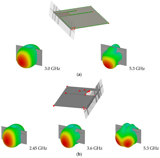

Figure 7.
Illustration of the computational mesh (time-domain solver of CST Microwave Studio) and 3D radiation patterns at the target operating frequencies (cf. Table 2) of selected designs optimized for these frequencies: (a) Antenna I, (b) Antenna II, (c) Antenna III. For all structures, hexahedral mesh is employed, and the underlying simulation procedure is the Finite Integration Technique (FIT) [111].
3.2. Results
The numerical results have been gathered in Table 4, Table 5 and Table 6 for Antennas I, II, and III, respectively. Figure 8 shows the evolution of the objective function, averaged over all performed runs of the respective algorithms. Furthermore, Figure 9, Figure 10 and Figure 11 show antenna characteristics at the final designs rendered in the chosen runs of the PSO optimizer using the feature-based problem formulation. The final optimal geometry parameter vectors for the designs shown in Figure 9, Figure 10 and Figure 11 are gathered in Table 7. The figures of interest are the average merit function values and their standard deviations. The latter is used as a measure of solution repeatability.
Table 4.
Antenna I: Optimization results.
Table 5.
Antenna II: Optimization results.
Table 6.
Antenna III: Optimization results.

Figure 8.
Objective function versus iteration index for minimax and feature-based formulations: (a) Antenna I; (b) Antenna II; (c) Antenna III. The merit function is averaged across the ten algorithm runs performed for each antenna structure.

Figure 9.
Reflection responses of Antenna I for designs obtained with PSO using feature-based formulation of the optimization problem. Shown are the results generated in the chosen executions of the algorithm: (a) design 1; (b) design 2; (c) design 3. The vertical lines indicate the target operational frequencies.

Figure 10.
Reflection responses of Antenna II for designs obtained with PSO using feature-based formulation of the optimization problem. Shown are the results generated in the chosen executions of the algorithm: (a) design 1; (b) design 2; (c) design 3. The vertical lines indicate the target operational frequencies.

Figure 11.
Reflection responses of Antenna III for designs obtained with PSO using feature-based formulation of the optimization problem. Shown are the results generated in the chosen executions of the algorithm: (a) design 1; (b) design 2; (c) design 3. The vertical lines indicate the target operational frequencies.
3.3. Discussion
The results shown in Table 4, Table 5 and Table 6 prove the advantages of feature-based formulation of the design task when applied to a global optimization of multi-band antenna structures. It can be noted that the average objective function is noticeably better for the feature-based approach after 20 iterations of the PSO algorithm. This is the case for all antenna structures considered in this study. After 50 iterations, the feature-based formulation yields better results for Antennas II and III, which are more challenging cases, both with regard to the design space dimensionality as well as the number of operating bands of the device. For Antenna I, both approaches render similar design qualities. At the same time, it can be noticed that the results’ repeatability (measured by the standard deviation of the results) is considerably better for feature-based formulations for Antennas II and III, which also indicates the advantages of the considered approach from the standpoint of design reliability.
Finally, utilization of response features allows for achieving noticeable computational speedup. For example, the number of iterations necessary to obtain the same average objective function levels as those produced by the feature-based formulation in 20 iterations, is about 30. The corresponding average speedup is therefore over 30 percent.
Let us also emphasize that—as mentioned before—the PSO algorithm was intentionally set up with a limited computational budget, which is to make the optimization costs reasonably low from the practical perspective. Although extending the optimization run beyond 50 iterations would likely lead to reducing the quality differences between the minimax and feature-based formulations, the primary objective of this work is to show that the latter brings in definite benefits under a tight CPU budget.
The presented results also demonstrate superiority of the performance of the proposed optimization procedure utilizing feature-based formulation of the design task over a local trust-region (TR) gradient-based algorithm. For each considered antenna structure, the average objective function value is significantly worse in the case of the TR routine than for the PSO algorithm (both using standard and feature-based formulation of the objective function). This is because the success rate of a TR algorithm is poor for all antennas: it equals 6/10 for Antenna I (meaning that the design specifications have been met in only six out of ten algorithm runs), and it is 4/10 for Antennas II and III. This clearly worsens solution repeatability for the local routine, which equals 5.0 (on average across all benchmark antenna sets), as compared to 3.3 (on average) for our algorithm with a higher computational budget.
The limitations of the proposed approach are twofold. Firstly, our algorithm solves the antenna design optimization task directly, i.e., no surrogate model is involved whatsoever. The employment of the feature-based formulation of the design task allows for slightly accelerating the process. Nevertheless, in the cases where the antenna simulation model is costly, the overall optimization expenses may be impractically high. Thus, the designer may need to default to the usage of machine-learning-based procedures. The second type of limitation stems from the fact the developed framework utilizes feature-based formulation of the design task. Thus, its employment is limited to the cases where easily identifiable characteristic points may be distinguished in the antenna frequency characteristics which enable encoding design specifications. Overall, the developed algorithm might not be as flexible as other frameworks that do not place any restrictions on the antenna response structure.
4. Conclusions
In this paper, we investigated potential benefits of incorporating feature-based formulation of design tasks when applied to nature-inspired optimization of antenna structures. The studies were focused on input characteristics of multi-band antennas, handling of which is representative in terms of the level of difficulty, and a multimodal nature of the problem. On the conceptual level, it has been demonstrated that problem reformulation, from the conventional (minimax) setup to that employing response features, significantly alters the functional landscape that needs to be tackled in the optimization process. These changes suggested that improved performance of the nature-inspired search processes may be expected. This was corroborated to the fullest extent through comprehensive numerical experiments conducted for three microstrip antennas, using a particle swarm optimizer as the algorithm of choice. In order to maintain the optimization expenses at practically acceptable levels, the computational budget was significantly restricted to only 500 objective function evaluations, with the intermediate results verified after 200 evaluations. The major findings are that exploiting problem-relevant knowledge in the form of response features to solve the considered antenna design optimization tasks noticeably improves both the quality of designs rendered by the algorithm and the overall reliability of the search process, as indicated by the lower values of standard deviation estimated from multiple independent algorithm runs. Future work will focus on the development of computationally-efficient, nature-inspired antenna optimization procedures involving both the response feature approach and other acceleration mechanisms, e.g., variable-resolution simulation models.
Author Contributions
Conceptualization, S.K. and A.P.-D.; methodology, S.K. and A.P.-D.; software, S.K., A.P.-D., and B.P.; validation, S.K. and A.P.-D.; formal analysis, S.K. and A.P.-D.; investigation, S.K. and A.P.-D.; resources, S.K.; data curation, A.P.-D. and B.P.; writing—original draft preparation, S.K. and A.P.-D.; writing—review and editing, S.K. and A.P.-D.; visualization, S.K., A.P.-D. and B.P.; supervision, S.K.; project administration, S.K.; funding acquisition, S.K. All authors have read and agreed to the published version of the manuscript.
Funding
This work was partially supported by the Icelandic Centre for Research (RANNIS) Grant 217771 and by the National Science Centre of Poland Grant 2020/37/B/ST7/01448.
Data Availability Statement
Data are contained within the article.
Acknowledgments
The authors would like to thank Dassault Systemes, France, for making CST Microwave Studio available.
Conflicts of Interest
The authors declare no conflict of interest. The funders had no role in the design of the study; in the collection, analyses, or interpretation of data; in the writing of the manuscript; or in the decision to publish the results.
References
- Nie, L.Y.; Lin, X.Q.; Wang, B.; Zhang, J. A planar multifunctional four-port antenna system for sub-urban mobile tablet. IEEE Access 2019, 7, 56986–56993. [Google Scholar] [CrossRef]
- Santamaria, L.; Ferrero, F.; Staraj, R.; Lizzi, L. Slot-based pattern reconfigurable ESPAR antenna for IoT applications. IEEE Trans. Ant. Propag. 2021, 69, 3635–3644. [Google Scholar] [CrossRef]
- Shu, C.; Wang, J.; Hu, S.; Yao, Y.; Yu, J.; Alfadhl, Y.; Chen, X. A wideband dual-circular-polarization horn antenna for mmwave wireless communications. IEEE Ant. Wirel. Propag. Lett. 2019, 18, 1726–1730. [Google Scholar] [CrossRef]
- Ciydem, M.; Miran, E.A. Dual-polarization wideband sub-6 GHZ suspended patch antenna for 5G base station. IEEE Ant. Wirel. Propag. Lett. 2020, 19, 1142–1146. [Google Scholar] [CrossRef]
- Chen, H.; Tsai, Y.; Sim, C.; Kuo, C. Broadband eight-antenna array design for sub-6 GHz 5G NR bands metal-frame smartphone applications. IEEE Ant. Wirel. Propag. Lett. 2020, 19, 1078–1082. [Google Scholar] [CrossRef]
- Zhang, K.; Jiang, Z.H.; Hong, W.; Werner, D.H. A low-profile and wideband triple-mode antenna for wireless body area network concurrent on-/off-body communications. IEEE Trans. Ant. Propag. 2020, 68, 1982–1994. [Google Scholar] [CrossRef]
- Felício, J.M.; Bioucas-Dias, J.M.; Costa, J.R.; Fernandes, C.A. Antenna design and near-field characterization for medical microwave imaging applications. IEEE Trans. Ant. Propag. 2019, 67, 4811–4824. [Google Scholar] [CrossRef]
- Hasani, H.; Silva, J.S.; Capdevila, S.; García-Vigueras, M.; Mosig, J.R. Dual-band circularly polarized transmitarray antenna for satellite communications at (20, 30) GHz. IEEE Trans. Ant. Propag. 2019, 67, 5325–5333. [Google Scholar] [CrossRef]
- Yoo, S.; Milyakh, Y.; Kim, H.; Hong, C.; Choo, H. Patch array antenna using a dual coupled feeding structure for 79 GHz automotive radar applications. IEEE Ant. Wirel. Propag. Lett. 2020, 19, 676–679. [Google Scholar] [CrossRef]
- Won, H.; Hong, Y.K.; Li, L.; Awasthi, A.; Nickerson, N.; Bryand, B.; Choi, M.; Yan, J.B.; Taylor, D.; O‘Neill, C.; et al. VHF/UHF open-sleeve dipole antenna array for airborne ice sounding and imaging radar. IEEE Ant. Wirel. Propag. Lett. 2021, 20, 883–887. [Google Scholar] [CrossRef]
- Cheng, Y.; Dong, Y. Wideband circularly polarized split patch antenna loaded with suspended rods. IEEE Ant. Wirel. Propag. Lett. 2021, 20, 229–233. [Google Scholar] [CrossRef]
- Kabir, S.S.; Khan, M.H.; Latif, S.I. A multi-band circularly polarized-shared aperture antenna for space applications at S and X bands. Electronics 2023, 12, 4439. [Google Scholar] [CrossRef]
- Chen, Z.; Song, W.; Wang, W. Wideband millimeter-wave MIMO antenna with a loaded dielectric cover for high-gain broadside radiation. Electronics 2023, 12, 4384. [Google Scholar] [CrossRef]
- Kumar, P.; Dwari, S.; Saini, R.K.; Mandal, M.K. Dual-band dual-sense polarization reconfigurable circularly polarized antenna. IEEE Ant. Wirel. Propag. Lett. 2019, 18, 64–68. [Google Scholar] [CrossRef]
- Tanoli, S.A.K.; Khan, M.I.; Fraz, Q.; Yang, X.; Shah, S.A. A compact beam-scanning leaky-wave antenna with improved performance. IEEE Ant. Wirel. Propag. Lett. 2018, 17, 825–828. [Google Scholar] [CrossRef]
- Ren, J.; Zhou, Z.; Wei, Z.H.; Ren, H.M.; Chen, Z.; Liu, Y.; Yin, Y.Z. Radiation pattern and polarization reconfigurable antenna using dielectric liquid. IEEE Trans. Ant. Propag. 2020, 68, 8174–8179. [Google Scholar] [CrossRef]
- Liu, P.; Jiang, W.; Sun, S.; Xi, Y.; Gong, S. Broadband and low-profile penta-polarization reconfigurable metamaterial antenna. IEEE Access 2020, 8, 21823–21831. [Google Scholar] [CrossRef]
- Anguera, J.; Andújar, A.; Jayasinghe, J. High-directivity microstrip patch antennas based on TModd-0 modes. IEEE Ant. Wirel. Propag. Lett. 2020, 19, 39–43. [Google Scholar] [CrossRef]
- Dong, Y.; Choi, J.; Itoh, T. Vivaldi antenna with pattern diversity for 0.7 to 2.7 GHz cellular band applications. IEEE Ant. Wirel. Propag. Lett. 2018, 17, 247–250. [Google Scholar] [CrossRef]
- Zhao, A.; Ren, Z. Size reduction of self-isolated MIMO antenna system for 5G Mobile phone applications. IEEE Ant. Wirel. Propag. Lett. 2019, 18, 152–156. [Google Scholar] [CrossRef]
- Li, R.; Guo, Y.; Zhang, B.; Du, G. A miniaturized circularly polarized implantable annular-ring antenna. IEEE Ant. Wirel. Propag. Lett. 2017, 16, 2566–2569. [Google Scholar] [CrossRef]
- Oh, J.-I.; Jo, H.-W.; Kim, K.-S.; Cho, H.; Yu, J.-W. A compact cavity-backed slot antenna using dual mode for IoT applications. IEEE Ant. Wirel. Propag. Lett. 2021, 20, 317–321. [Google Scholar] [CrossRef]
- Liu, J.; Esselle, K.P.; Hay, S.G.; Zhong, S. Effects of printed UWB antenna miniaturization on pulse fidelity and pattern stability. IEEE Trans. Ant. Prop. 2014, 62, 3903–3910. [Google Scholar] [CrossRef]
- Francis, R.; Butt, S.I.; Singh, J.; Guelzow, P.; Eimertenbrink, R.; Hein, M.A. Suitability of dual-band, dual-polarized patch antennas with a superstrate for the miniaturization of ku-band antenna arrays for automotive applications. Appl. Sci. 2023, 13, 10867. [Google Scholar] [CrossRef]
- Zhu, S.; Liu, H.; Wen, P.; Chen, Z.; Xu, H. Vivaldi antenna array using defected ground structure for edge effect restraint and back radiation suppression. IEEE Ant. Wirel. Propag. Lett. 2020, 19, 84–88. [Google Scholar] [CrossRef]
- Hu, W.; Yin, Y.; Yang, X.; Fei, P. Compact multiresonator-loaded planar antenna for multiband operation. IEEE Trans. Ant. Propag. 2013, 61, 2838–2841. [Google Scholar] [CrossRef]
- Podilchak, S.K.; Johnstone, J.C.; Caillet, M.; Clénet, M.; Antar, Y.M.M. A compact wideband dielectric resonator antenna with a meandered slot ring and cavity backing. IEEE Ant. Wirel. Propag. Lett. 2016, 15, 909–913. [Google Scholar] [CrossRef]
- Ding, Z.; Jin, R.; Geng, J.; Zhu, W.; Liang, X. Varactor loaded pattern reconfigurable patch antenna with shorting pins. IEEE Trans. Ant. Propag. 2019, 67, 6267–6277. [Google Scholar] [CrossRef]
- Li, W.; Liu, S.; Deng, J.; Hu, Z.; Zhou, Z. A compact SIW monopulse antenna array based on microstrip feed. IEEE Ant. Wirel. Propag. Lett. 2021, 20, 93–97. [Google Scholar] [CrossRef]
- Wang, Z.; Dong, Y. Low-profile omnidirectional WIFI antennas with pattern reconfigurability inspired by meta-resonators. IEEE Trans. Ant. Propag. 2020, 68, 6935–6942. [Google Scholar] [CrossRef]
- Al-Bawri, S.S.; Islam, M.T.; Shabbir, T.; Muhammad, G.; Islam, M.S.; Wong, H.Y. Hexagonal shaped near zero index (NZI) metamaterial based MIMO antenna for millimeter-wave application. IEEE Access 2020, 8, 181003–181013. [Google Scholar] [CrossRef]
- Mosalanejad, M.; Ocket, I.; Soens, C.; Vandenbosch, G.A.E. Multi-layer PCB bow-tie antenna array for (77–81) GHz radar applications. IEEE Trans. Ant. Propag. 2020, 68, 2379–2386. [Google Scholar] [CrossRef]
- Konstantinidis, K.; Feresidis, A.P.; Hall, P.S. Broadband sub-wavelength profile high-gain antennas based on multi-layer metasurfaces. IEEE Trans. Ant. Propag. 2015, 63, 423–427. [Google Scholar] [CrossRef]
- Wang, C.; Shih, M.; Chen, L. A wideband open-slot antenna with dual-band circular polarization. IEEE Ant. Wirel. Propag. Lett. 2015, 14, 1306–1309. [Google Scholar] [CrossRef]
- Ghaderi, M.; Moradi, G.; Mousavi, P. Numerical study on a wideband plasma folded-dipole antenna. IEEE Ant. Wirel. Propag. Lett. 2017, 16, 1253–1256. [Google Scholar] [CrossRef]
- Tomasson, J.A.; Koziel, S.; Pietrenko-Dabrowska, A. Quasi-global optimization of antenna structures using principal components and affine subspace-spanned surrogates. IEEE Access 2020, 8, 50078–50084. [Google Scholar] [CrossRef]
- Tomasson, J.A.; Pietrenko-Dabrowska, A.; Koziel, S. Expedited globalized antenna optimization by principal components and variable-fidelity EM simulations: Application to microstrip antenna design. Electronics 2020, 9, 673. [Google Scholar] [CrossRef]
- Koziel, S.; Ogurtsov, S. Simulation-Based Optimization of Antenna Arrays; World Scientific: Singapore, 2019. [Google Scholar]
- Kovaleva, M.; Bulger, D.; Esselle, K.P. Comparative study of optimization algorithms on the design of broadband antennas. IEEE J. Multiscale Multiphys. Comp. Techn. 2020, 5, 89–98. [Google Scholar] [CrossRef]
- Peiyuan, L.; Congsi, W.; Binbin, X.; Yu, S.; Song, X. Gradient-based optimization method for producing a contoured beam with single-fed reflector antenna. J. Syst. Eng. Electron. 2019, 30, 22–29. [Google Scholar]
- Koziel, S.; Pietrenko-Dabrowska, A. Rapid multi-objective optimization of antennas using nested kriging surrogates and single-fidelity EM simulation models. Eng. Comp. 2019, 37, 1491–1512. [Google Scholar] [CrossRef]
- Liu, Y.; Li, M.; Haupt, R.L.; Guo, Y.J. Synthesizing shaped power patterns for linear and planar antenna arrays including mutual coupling by refined joint rotation/phase optimization. IEEE Trans. Ant. Propag. 2020, 68, 4648–4657. [Google Scholar] [CrossRef]
- Liang, S.; Fang, Z.; Sun, G.; Liu, Y.; Qu, G.; Zhang, Y. Sidelobe reductions of antenna arrays via an improved chicken swarm optimization approach. IEEE Access 2020, 8, 37664–37683. [Google Scholar] [CrossRef]
- Wu, R.; Cao, S.; Liu, Y.; Cai, S. A wideband low-profile dual-polarized antenna based on a metasurface. Electronics 2023, 12, 4739. [Google Scholar] [CrossRef]
- Tang, M.; Chen, X.; Li, M.; Ziolkowski, R.W. Particle swarm optimized, 3-D-printed, wideband, compact hemispherical antenna. IEEE Ant. Wirel. Propag. Lett. 2018, 17, 2031–2035. [Google Scholar] [CrossRef]
- Pallarés-Rodríguez, L.; Locubiche-Serra, S.; Foreman-Campins, G.; Seco-Granados, G.; López-Salcedo, J.A. Beamforming techniques for resilient navigation with small antenna arrays. Eng. Proc. 2023, 54, 27. [Google Scholar]
- Koziel, S.; Pietrenko-Dabrowska, A. Design-oriented computationally-efficient feature-based surrogate modelling of multi-band antennas with nested kriging. AEU Int. J. Electron. Commun. 2020, 120, 153202. [Google Scholar] [CrossRef]
- Yang, C.; Zhang, J.; Tong, M.S. An FFT-accelerated particle swarm optimization method for solving far-field inverse scattering problems. IEEE Trans. Ant. Propag. 2021, 69, 1078–1093. [Google Scholar] [CrossRef]
- Liu, X.; Du, B.; Zhou, J.; Xie, L. Optimal design of elliptical beam cassegrain antenna. IEEE Access 2021, 9, 120765–120773. [Google Scholar] [CrossRef]
- Sharma, A. Nature inspired algorithms with randomized hypercomputational perspective. Inf. Sci. 2022, 608, 670–695. [Google Scholar] [CrossRef]
- Singh, K.; Esselle, K. Suppressing sidelobes in metasurface-based antennas using a cross-entropy method variant and full wave electromagnetic simulations. Electronics 2023, 12, 4229. [Google Scholar] [CrossRef]
- Goldberg, D.E.; Holland, J.H. Genetic Algorithms and Machine Learning; Springer: New York, NY, USA, 1988. [Google Scholar]
- Michalewicz, Z. Genetic Algorithms + Data Structures = Evolution Programs; Springer: New York, NY, USA, 1996. [Google Scholar]
- Rayno, J.; Iskander, M.F.; Kobayashi, M.H. Hybrid genetic programming with accelerating genetic algorithm optimizer for 3-D metamaterial design. IEEE Ant. Wirel. Propag. Lett. 2016, 15, 1743–1746. [Google Scholar] [CrossRef]
- Zhao, H.; Zhang, C.; Zhang, B. A decomposition-based many-objective ant colony optimization algorithm with adaptive reference points. Inf. Sci. 2020, 540, 435–448. [Google Scholar] [CrossRef]
- Hu, Y.; Zhang, Y.; Gao, X.; Gong, D.; Song, X.; Guo, Y.; Wang, J. A federated feature selection algorithm based on particle swarm optimization under privacy protection. Knowl.-Based Syst. 2023, 260, 110122. [Google Scholar] [CrossRef]
- Behera, B.R.; Alsharif, M.H.; Jahid, A. Investigation of a circularly polarized metasurface antenna for hybrid wireless applications. Micromachines 2023, 14, 2172. [Google Scholar] [CrossRef] [PubMed]
- Yang, S.H.; Kiang, J.F. Optimization of sparse linear arrays using harmony search algorithms. IEEE Trans. Ant. Prop. 2015, 63, 4732–4738. [Google Scholar] [CrossRef]
- Baumgartner, P.; Baurnfeind, T.; Biro, O.; Hackl, A.; Magele, C.; Renhart, W.; Torchio, R. Multi-objective optimization of Yagi-Uda antenna applying enhanced firefly algorithm with adaptive cost function. IEEE Trans. Magn. 2018, 54, 8000504. [Google Scholar] [CrossRef]
- Li, X.; Luk, K.M. The grey wolf optimizer and its applications in electromagnetics. IEEE Trans. Ant. Prop. 2020, 68, 2186–2197. [Google Scholar] [CrossRef]
- Zheng, T.; Liu, Y.; Sun, G.; Zhang, L.; Lian, S.; Wang, A.; Zhou, X. IWORMLF: Improved invasive weed optimization with random mutation and Lévy flight for beam pattern optimizations of linear and circular antenna arrays. IEEE Access 2020, 8, 19460–19478. [Google Scholar] [CrossRef]
- Darvish, A.; Ebrahimzadeh, A. Improved fruit-fly optimization algorithm and its applications in antenna arrays synthesis. IEEE Trans. Antennas Propag. 2018, 66, 1756–1766. [Google Scholar] [CrossRef]
- Bayraktar, Z.; Komurcu, M.; Bossard, J.A.; Werner, D.H. The wind driven optimization technique and its application in electromagnetics. IEEE Trans. Antennas Propag. 2013, 61, 2745–2757. [Google Scholar] [CrossRef]
- Abdel-Basset, M.; Mohamed, R.; Jameel, M.; Abouhawwash, M. Nutcracker optimizer: A novel nature-inspired metaheuristic algorithm for global optimization and engineering design problems. Knowl.-Based Syst. 2023, 262, 110248. [Google Scholar] [CrossRef]
- John, M.; Ammann, M.J. Antenna optimization with a computationally efficient multiobjective evolutionary algorithm. IEEE Trans. Ant. Propag. 2009, 57, 260–263. [Google Scholar] [CrossRef]
- Simon, D. Evolutionary Optimization Algorithms; John Wiley & Sons, Inc.: Hoboken, NJ, USA, 2013. [Google Scholar]
- Karimkashi, S.; Kishk, A.A. Invasive weed optimization and its features in electromagnetics. IEEE Trans. Antennas Propag. 2010, 58, 1269–1278. [Google Scholar] [CrossRef]
- Li, W.; Zhang, Y.; Shi, X. Advanced fruit fly optimization algorithm and its application to irregular subarray phased array antenna synthesis. IEEE Access 2019, 7, 165583–165596. [Google Scholar] [CrossRef]
- Queipo, N.V.; Haftka, R.T.; Shyy, W.; Goel, T.; Vaidynathan, R.; Tucker, P.K. Surrogate based analysis and optimization. Prog. Aerosp. Sci. 2005, 41, 1–28. [Google Scholar] [CrossRef]
- de Villiers, D.I.L.; Couckuyt, I.; Dhaene, T. Multi-objective optimization of reflector antennas using kriging and probability of improvement. In Proceedings of the 2017 IEEE International Symposium on Antennas and Propagation & USNC/URSI National Radio Science Meeting, San Diego, CA, USA, 9–14 July 2017; pp. 985–986. [Google Scholar]
- Jacobs, J.P. Characterization by Gaussian processes of finite substrate size effects on gain patterns of microstrip antennas. IET Microw. Ant. Prop. 2016, 10, 1189–1195. [Google Scholar] [CrossRef]
- Zhang, Y. Chaotic neural network algorithm with competitive learning for global optimization. Knowl.-Based Syst. 2021, 231, 107405. [Google Scholar] [CrossRef]
- Alzahed, A.M.; Mikki, S.M.; Antar, Y.M.M. Nonlinear mutual coupling compensation operator design using a novel electromagnetic machine learning paradigm. IEEE Ant. Wireless Prop. Lett. 2019, 18, 861–865. [Google Scholar] [CrossRef]
- Liu, B.; Aliakbarian, H.; Ma, Z.; Vandenbosch, G.A.E.; Gielen, G.; Excell, P. An efficient method for antenna design optimization based on evolutionary computation and machine learning techniques. IEEE Trans. Ant. Propag. 2014, 62, 7–18. [Google Scholar] [CrossRef]
- Couckuyt, I.; Declercq, F.; Dhaene, T.; Rogier, H.; Knockaert, L. Surrogate-based infill optimization applied to electromagnetic problems. Int. J. RF Microw. Computt.-Aided Eng. 2010, 20, 492–501. [Google Scholar] [CrossRef]
- Choi, K.; Jang, D.; Kang, S.; Lee, J.; Chung, T.; Kim, H. Hybrid algorithm combing genetic algorithm with evolution strategy for antenna design. IEEE Trans. Magn. 2016, 52, 7209004. [Google Scholar] [CrossRef]
- Xia, B.; Ren, Z.; Koh, C.S. Utilizing kriging surrogate models for multi-objective robust optimization of electromagnetic devices. IEEE Trans. Magn. 2014, 50, 7017104. [Google Scholar] [CrossRef]
- Koziel, S.; Pietrenko-Dabrowska, A. Recent advances in accelerated multi-objective design of high-frequency structures using knowledge-based constrained modeling approach. Knowl.-Based Syst. 2021, 214, 106726. [Google Scholar] [CrossRef]
- Pietrenko-Dabrowska, A.; Koziel, S. Antenna modeling using variable-fidelity EM simulations and constrained co-kriging. IEEE Access 2020, 8, 91048–91056. [Google Scholar] [CrossRef]
- Liu, Y.; Liu, B.; Ur-Rehman, M.; Imran, M.A.; Akinsolu, M.O.; Excell, P.; Hua, Q. An efficient method for antenna design based on a self-adaptive Bayesian neural network-assisted global optimization technique. IEEE Trans. Antennas Propag. 2022, 70, 11375–11388. [Google Scholar] [CrossRef]
- Xue, L.; Liu, B.; Yu, Y.; Cheng, Q.S.; Imran, M.; Qiao, T. An unsupervised microwave filter design optimization method based on a hybrid surrogate model-assisted evolutionary algorithm. IEEE Trans. Microw. Theory Techn. 2023, 71, 1159–1170. [Google Scholar] [CrossRef]
- Wang, Z.; Qin, J.; Hu, Z.; He, J.; Tang, D. Multi-objective antenna design based on bp neural network surrogate model optimized by improved sparrow search algorithm. Appl. Sci. 2022, 12, 12543. [Google Scholar] [CrossRef]
- Koziel, S.; Pietrenko-Dabrowska, A. Global EM-driven optimization of multi-band antennas using knowledge-based inverse response-feature surrogates. Knowl.-Based Syst. 2021, 227, 107189. [Google Scholar] [CrossRef]
- Pietrenko-Dabrowska, A.; Koziel, S.; Al-Hasan, M. Accelerated parameter tuning of antenna structures using inverse and feature-based forward kriging surrogates. Int. J. Numer. Model. 2012, 34, e2880. [Google Scholar]
- Koziel, S.; Pietrenko-Dabrowska, A. Expedited feature-based quasi-global optimization of multi-band antennas with Jacobian variability tracking. IEEE Access 2020, 8, 83907–83915. [Google Scholar] [CrossRef]
- Koziel, S.; Ogurtsov, S. Antenna Design by Simulation-Driven Optimization; Surrogate-based approach; Springer: New York, NY, USA, 2014. [Google Scholar]
- Premkumar, M.; Jangir, P.; Sowmya, R. MOGBO: A new Multiobjective Gradient-Based Optimizer for real-world structural optimization problems. Knowl.-Based Syst. 2021, 218, 106856. [Google Scholar] [CrossRef]
- Koziel, S.; Bekasiewicz, A. Multi-Objective Design of Antennas Using Surrogate Models; World Scientific: Singapore, 2016. [Google Scholar]
- Haq, M.A.; Koziel, S. Ground plane alterations for design of high-isolation compact wideband MIMO antenna. IEEE Access 2018, 6, 48978–48983. [Google Scholar] [CrossRef]
- Ruan, J.; Chen, T.; Yu, J.; Yao, Y.; Chen, X. Geometric space optimization based on intelligent algorithm for tri-reflector compact antenna test range. IEEE Trans. Antennas Propag. 2023, 71, 7000–7005. [Google Scholar] [CrossRef]
- Balanis, C.A. Antenna Theory. Analysis and Design, 4th ed.; Wiley: Hoboken, NJ, USA, 2016. [Google Scholar]
- Volakis, J. (Ed.) Antenna Engineering Handbook, 5th ed.; McGraw-Hill: New York, NY, USA, 2019. [Google Scholar]
- Pietrenko-Dabrowska, A.; Koziel, S. Simulation-driven antenna modeling by means of response features and confined domains of reduced dimensionality. IEEE Access 2020, 8, 228942–228954. [Google Scholar] [CrossRef]
- Clerc, M. Particle Swarm Optimization, 1st ed.; Wiley-ISTE: Hoboken, NJ, USA, 2013. [Google Scholar]
- Lazinica, A. Particle Swarm Optimization; Intechopen: Rijeka, Croatia, 2009. [Google Scholar]
- Zhao, Q.; Li, C. Two-stage multi-swarm particle swarm optimizer for unconstrained and constrained global optimization. IEEE Access 2020, 8, 124905–124927. [Google Scholar] [CrossRef]
- Khan, R.A.; Yang, S.; Fahad, S.; Khan, S.U. A modified particle swarm optimization with a smart particle for inverse problems in electromagnetic devices. IEEE Access 2021, 9, 99932–99943. [Google Scholar] [CrossRef]
- Xiong, S.; Chen, Z.; Jiang, N.; Zhao, J.; Liu, L. Performance optimization of multipair massive MIMO polarized relay systems. Electronics 2023, 12, 3184. [Google Scholar] [CrossRef]
- Gravas, I.P.; Zaharis, Z.D.; Lazaridis, P.I.; Yioultsis, T.V.; Kantartzis, N.V.; Antonopoulos, C.S.; Chochliouros, I.P.; Xenos, T.D. Optimal design of aperiodic reconfigurable antenna array suitable for broadcasting applications. Electronics 2020, 9, 818. [Google Scholar] [CrossRef]
- Jiang, Z.J.; Zhao, S.; Chen, Y.; Cui, T.J. Beamforming optimization for time-modulated circular-aperture grid array with DE algorithm. IEEE Ant. Wirel. Propag. Lett. 2018, 17, 2434–2438. [Google Scholar] [CrossRef]
- Kennedy, J.; Eberhart, R.C. Swarm Intelligence; Morgan Kaufmann: San Francisco, CA, USA, 2001. [Google Scholar]
- Conn, A.R.; Gould, N.I.M.; Toint, P.L. Trust Region Methods; SIAM: Philadelphia, PA, USA, 2000. [Google Scholar]
- Chen, Y.-C.; Chen, S.-Y.; Hsu, P. Dual-band slot dipole antenna fed by a coplanar waveguide. In Proceedings of the 2006 IEEE Antennas and Propagation Society International Symposium, Albuquerque, NM, USA, 9–14 July 2006; pp. 3589–3592. [Google Scholar]
- Consul, P. Triple band gap coupled microstrip U-slotted patch antenna using L-slot DGS for wireless applications. In Proceedings of the 2015 Communication, Control and Intelligent Systems (CCIS), Mathura, India, 7–8 November 2015; pp. 31–34. [Google Scholar]
- Garbuglia, F.; Spina, D.; Deschrijver, D.; Couckuyt, I.; Dhaene, T. Bayesian optimization for microwave devices using deep GP spectral surrogate models. IEEE Trans. Microw. Theory Techn. 2023, 71, 2311–2318. [Google Scholar] [CrossRef]
- Zhou, J.; Yang, Z.; Si, Y.; Knag, L.; Li, H.; Wang, M.; Zhang, Z. A trust-region parallel Bayesian optimization method for simulation-driven antenna design. IEEE Trans. Antennas Propag. 2021, 69, 3966–3981. [Google Scholar] [CrossRef]
- Gupta, N.; Saxena, J.; Bhatia, K.S. Optimized metamaterial-loaded fractal antenna using modified hybrid BF-PSO algorithm. J. Neural Comput. Appl. 2020, 32, 7153–7169. [Google Scholar] [CrossRef]
- Uluslu, A. Chameleon swarm algorithm assisted optimization of U-slot patch antenna for quad-band applications. IEEE Access 2022, 10, 74152–74163. [Google Scholar] [CrossRef]
- Li, Q.Q.; Chu, Q.X.; Chang, Y.-L. Design of compact high-isolation MIMO antenna with multiobjective mixed optimization algorithm. IEEE Antennas Wirel. Propag. Let. 2020, 19, 1306–1310. [Google Scholar] [CrossRef]
- Aldhafeeri, A.; Rahmat-Samii, Y. Brain storm optimization for electromagnetic applications: Continuous and discrete. IEEE Trans. Antennas Propag. 2019, 67, 2710–2722. [Google Scholar] [CrossRef]
- Weiland, T. A discretization method for the solution of maxwell’s equations for six-component fields. Arch. Elektron. Uebertragungstechnik 1977, 31, 116–120. (In German) [Google Scholar]
Disclaimer/Publisher’s Note: The statements, opinions and data contained in all publications are solely those of the individual author(s) and contributor(s) and not of MDPI and/or the editor(s). MDPI and/or the editor(s) disclaim responsibility for any injury to people or property resulting from any ideas, methods, instructions or products referred to in the content. |
© 2024 by the authors. Licensee MDPI, Basel, Switzerland. This article is an open access article distributed under the terms and conditions of the Creative Commons Attribution (CC BY) license (https://creativecommons.org/licenses/by/4.0/).