
A Metamaterial Bandpass Filter with End-Fire Coaxial Coupling


Abstract
1. Introduction
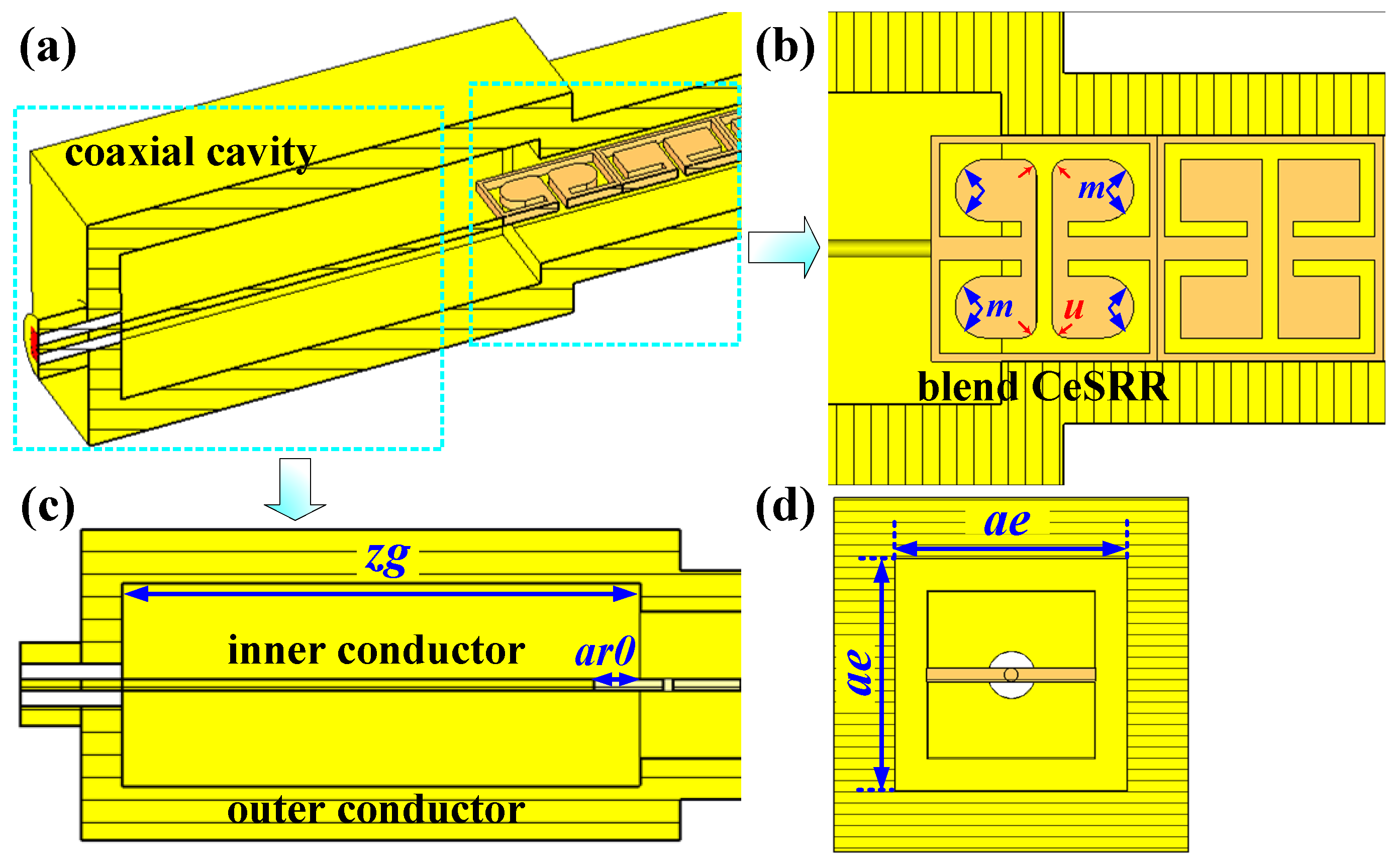
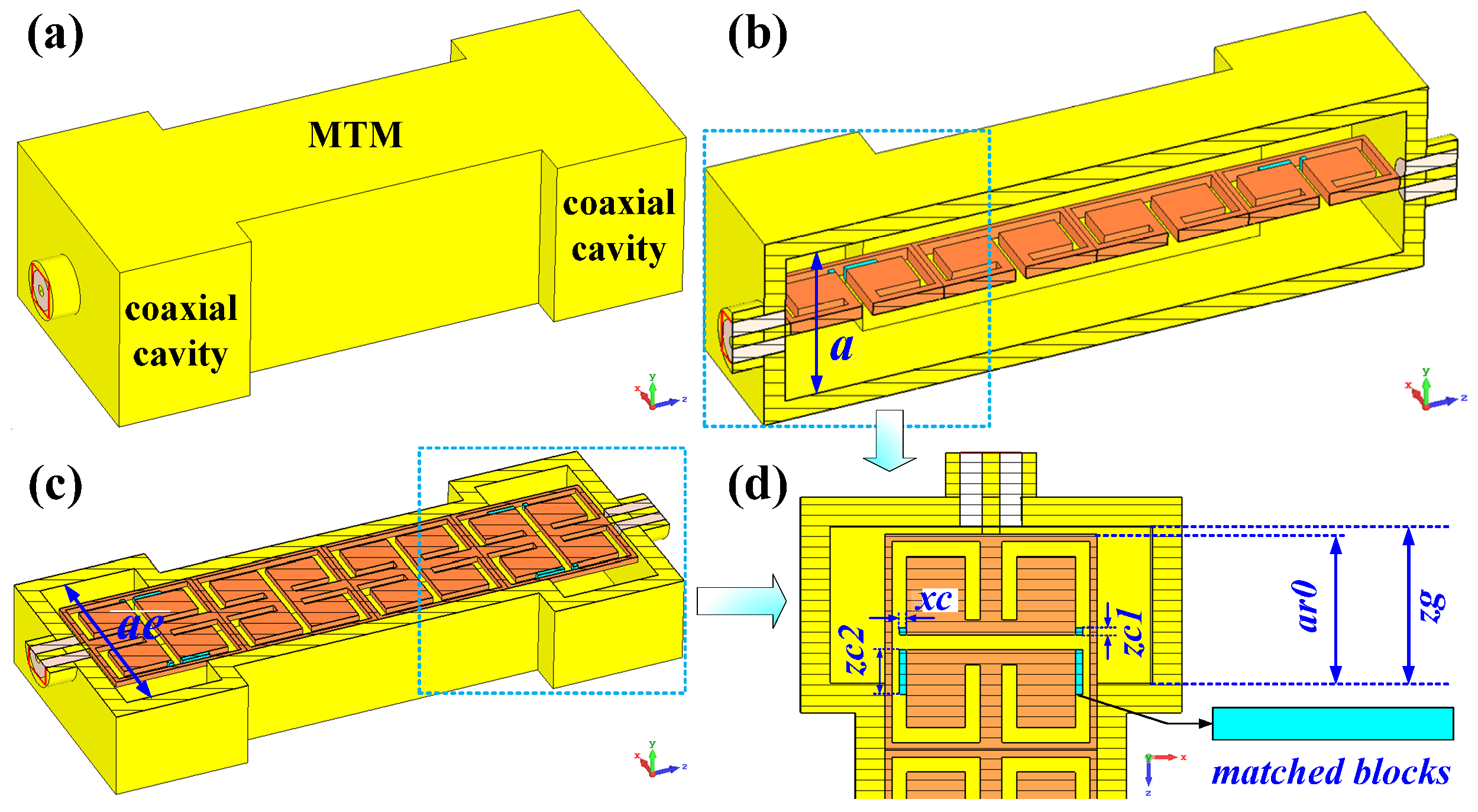
2. Filter Design
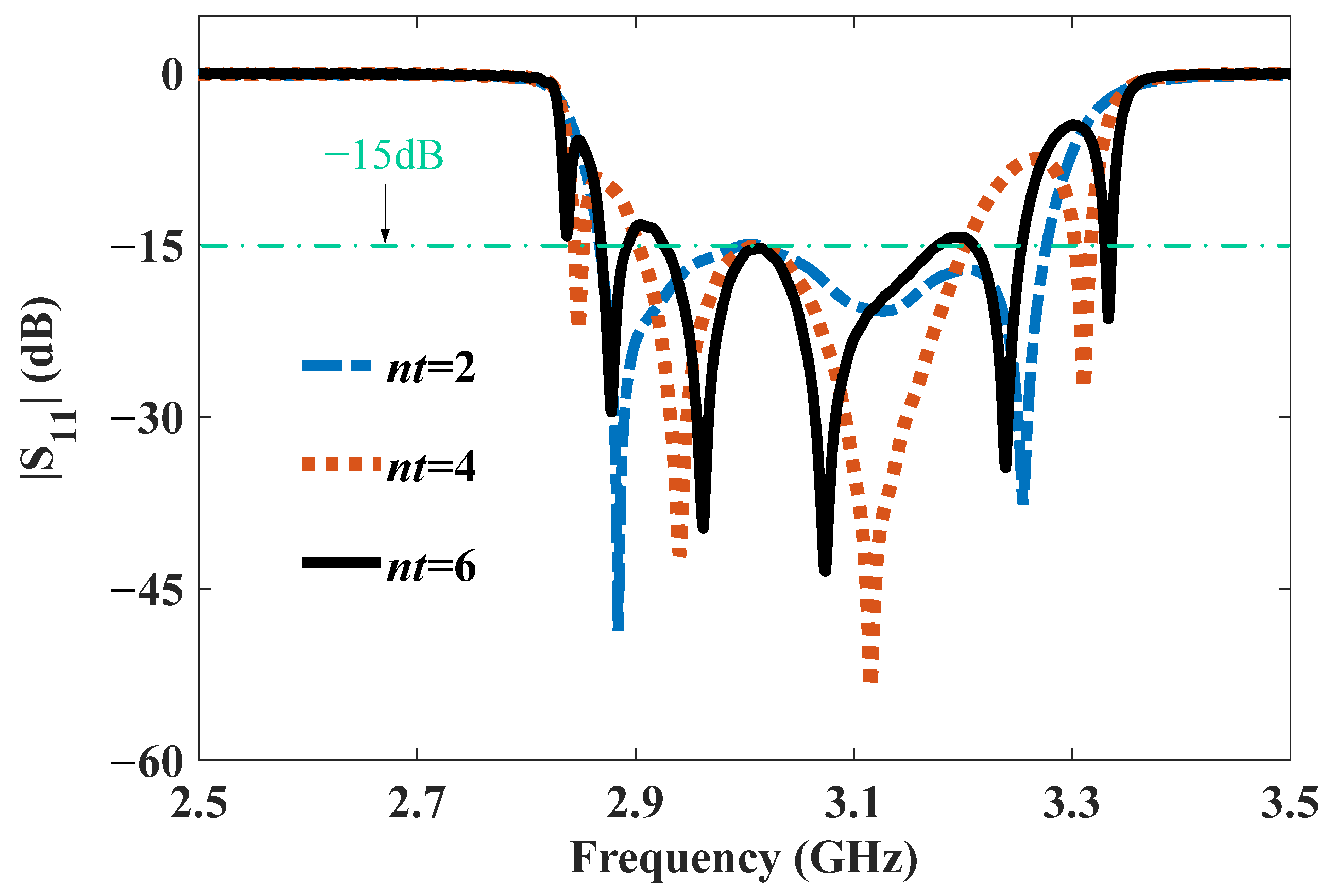
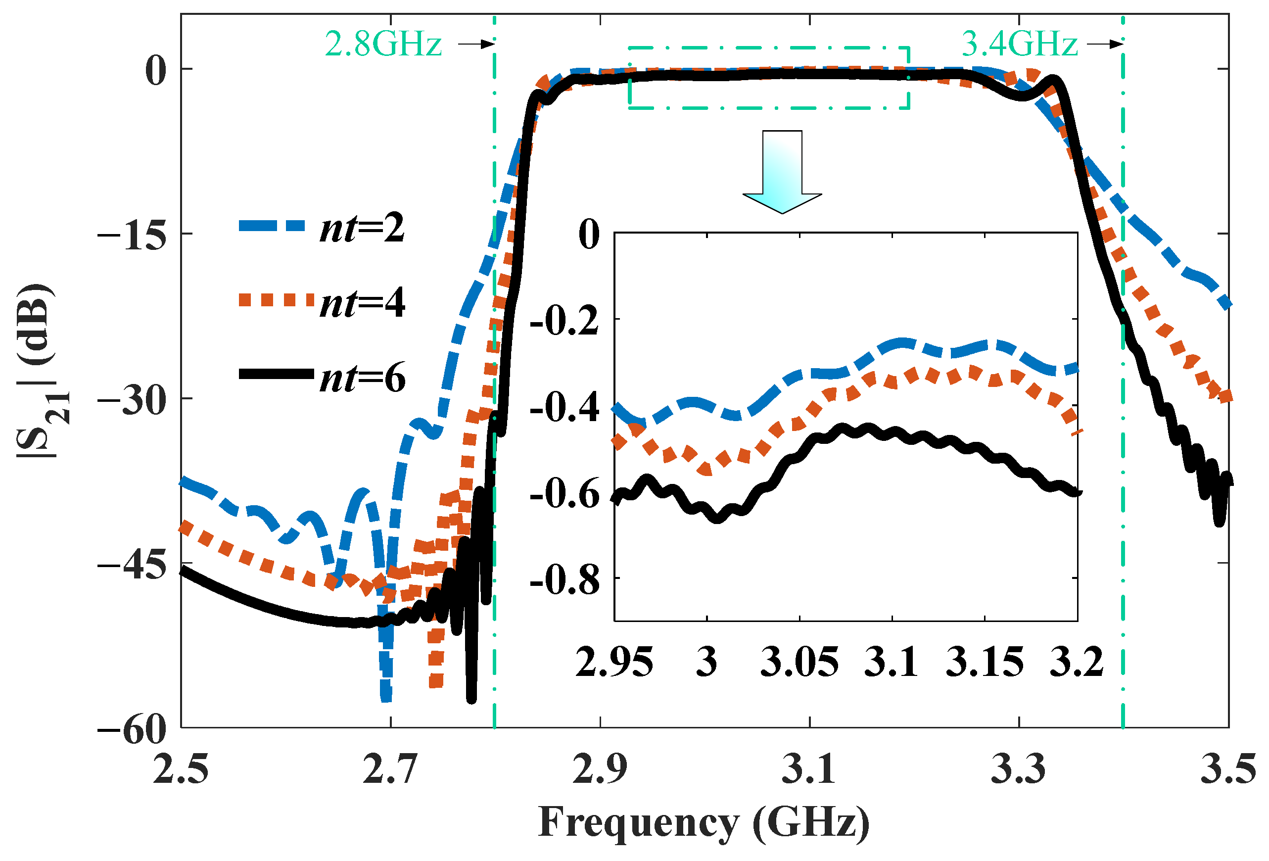
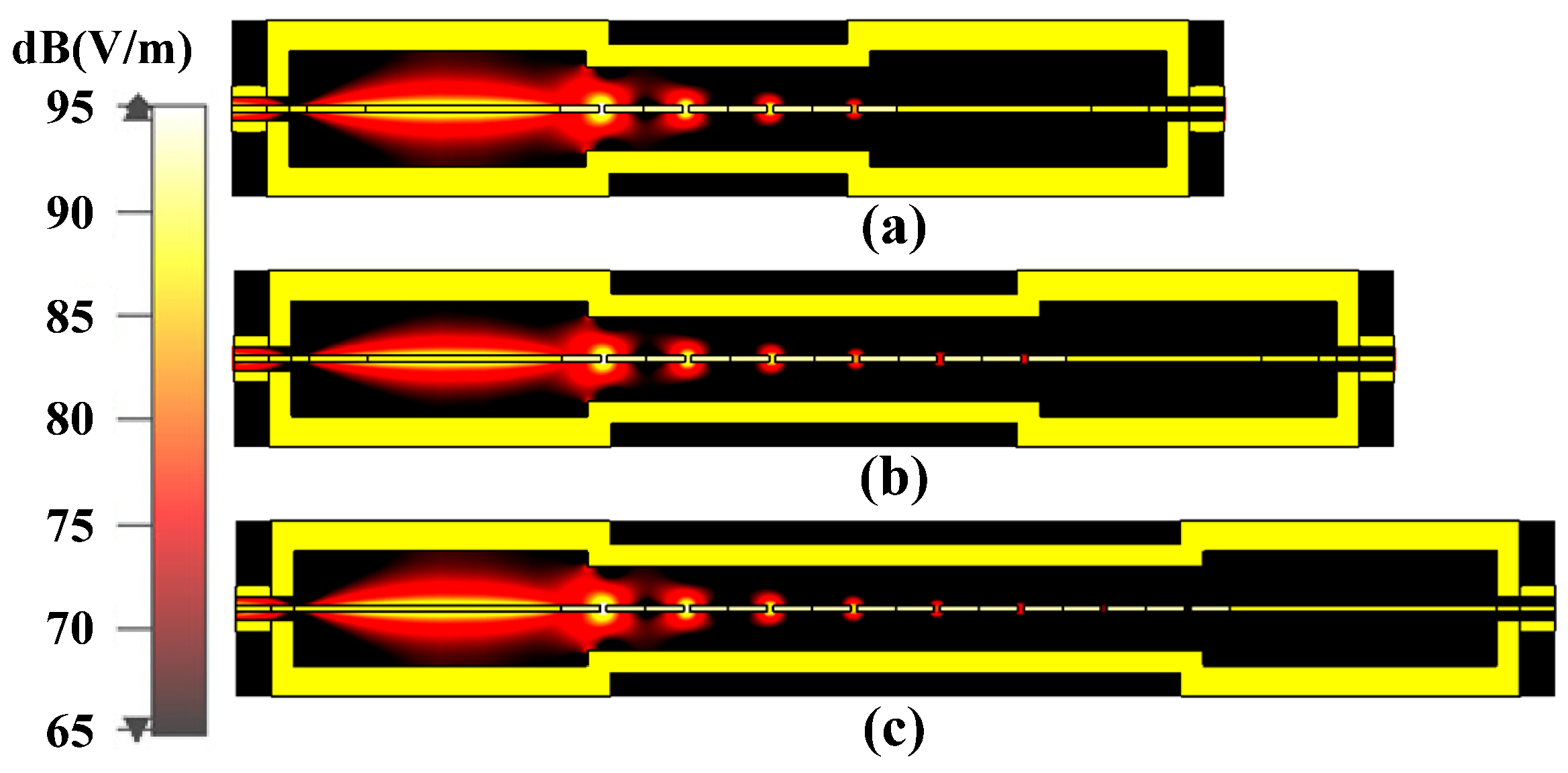
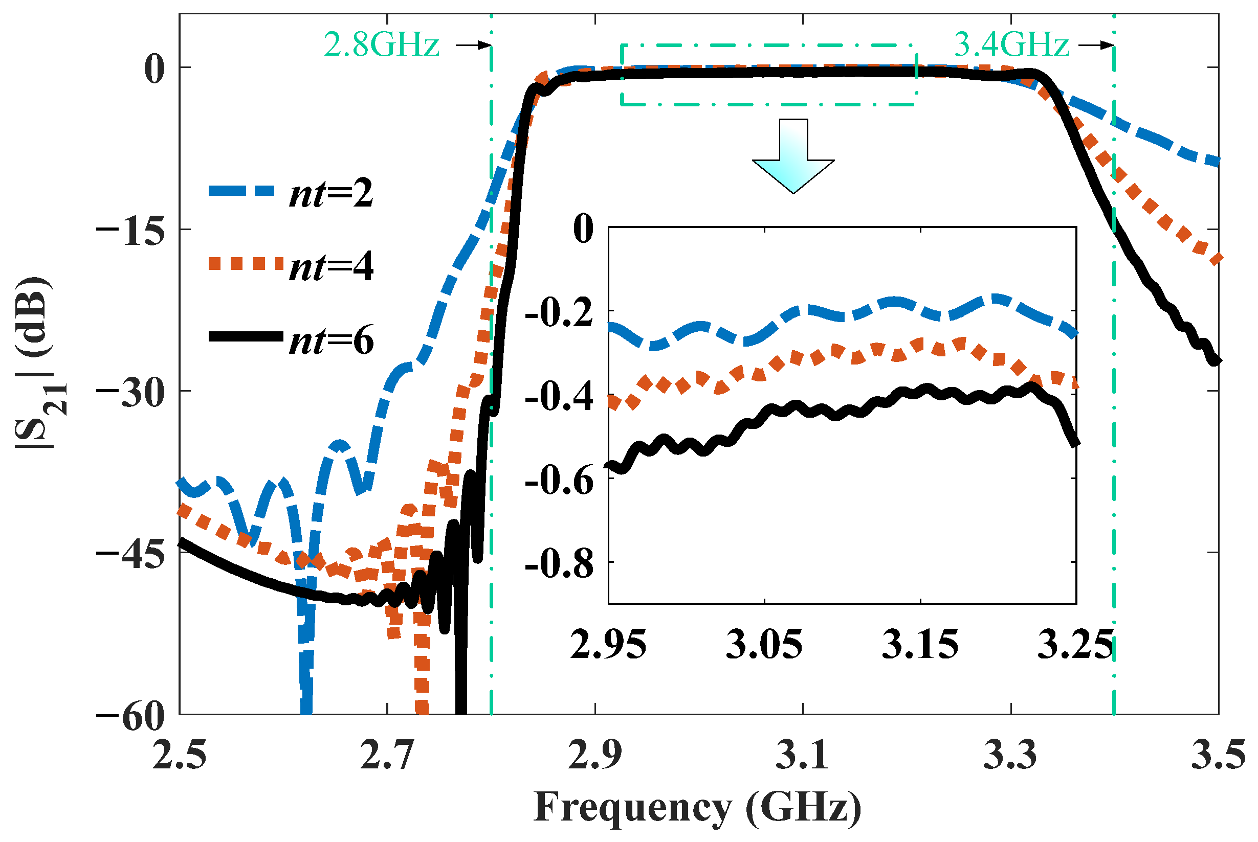
3. Results of the MTM BPF
4. Discussion
5. Conclusions
Author Contributions
Funding
Data Availability Statement
Conflicts of Interest
References
- Choudhary, D.K.; Chaudhary, R.K. Compact lowpass and dual-band bandpass filter with controllable transmission zero/center frequencies/passband bandwidth. IEEE Trans. Circuits Syst. II Exp. Briefs 2020, 67, 1044–1048. [Google Scholar] [CrossRef]
- Zhang, A.; Xu, J.; Liu, Z.; Zhang, Y. Microstrip quasi-elliptic absorptive bandpass filter with ultra-wide reflectionless range and compact size. Electronics 2024, 13, 1841. [Google Scholar] [CrossRef]
- Zhang, Q.L.; Wang, B.Z.; Zhao, D.S.; Wu, K. A compact half-mode substrate integrated waveguide bandpass filter with wide out-of-band rejection. IEEE Microw. Wirel. Compon. Lett. 2016, 26, 501–503. [Google Scholar] [CrossRef]
- Liu, Z.; Xia, H.; Liu, H.; Li, L. Slow wave gap waveguide with bandpass filtering functionality. IEEE Microw. Wirel. Compon. Lett. 2022, 32, 953–956. [Google Scholar] [CrossRef]
- Ali, A.; Hu, Z. Metamaterial resonator based wave propagation notch for ultrawideband filter applications. IEEE Antennas Wirel. Propag. Lett. 2008, 7, 210–212. [Google Scholar] [CrossRef]
- Horestani, A.K.; Withayachumnankul, W.; Chahadih, A.; Ghaddar, A.; Zehar, M.; Abbott, D.; Fumeaux, C.; Akalin, T. Metamaterial-inspired bandpass filters for terahertz surface waves on goubau lines. IEEE Trans. Terahertz Sci. Technol. 2013, 3, 851–858. [Google Scholar] [CrossRef]
- Noor, A.; Koziel, S. Dual-polarized wideband bandpass metasurface-based filter. IEEE Antennas Wirel. Propag. Lett. 2024, 23, 404–408. [Google Scholar] [CrossRef]
- Shapiro, M.A.; Trendafilov, S.; Urzhumov, Y.; Alù, A.; Temkin, R.J.; Shvets, G. Active negative-index metamaterial powered by an electron beam. Phys. Rev. B 2012, 86, 085132. [Google Scholar] [CrossRef]
- Duan, Z.; Hummelt, J.S.; Shapiro, M.A.; Temkin, R.J. Sub-wavelength waveguide loaded by a complementary electric metamaterial for vacuum electron devices. Phys. Plasmas 2014, 21, 103301. [Google Scholar] [CrossRef]
- Duan, Z.; Shapiro, M.A.; Schamiloglu, E.; Behdad, N.; Gong, Y.; Booske, J.H.; Basu, B.N.; Temkin, R.J. Metamaterial-inspired vacuum electron devices and accelerators. IEEE Trans. Electron Device 2019, 66, 207–218. [Google Scholar] [CrossRef]
- De Alleluia, A.B.; Abdelshafy, A.F.; Ragulis, P.; Kuskov, A.; Andreev, D.; Othman, M.A.K.; Martinez-Hernandez, B.; Schamiloglu, E.; Figotin, A.; Capolino, F. Experimental testing of a 3-d-printed metamaterial slow wave structure for high-power microwave generation. IEEE Trans. Plasma Sci. 2020, 48, 4356–4364. [Google Scholar] [CrossRef]
- Lu, X.; Picard, J.F.; Shapiro, M.A.; Mastovsky, I.; Temkin, R.J.; Conde, M.; Power, J.G.; Shao, J.; Wisniewski, E.E.; Peng, M.; et al. Coherent high-power RF wakefield generation by electron bunch trains in a metamaterial structure. Appl. Phys. Lett. 2020, 116, 264102. [Google Scholar] [CrossRef]
- Hummelt, J.S.; Lewis, S.M.; Shapiro, M.A.; Temkin, R.J. Design of a metamaterial-based backward-wave oscillator. IEEE Trans. Plasma Sci. 2014, 42, 930–936. [Google Scholar] [CrossRef]
- Tang, X.; Duan, Z.; Ma, X.; Li, S.; Wang, F.; Wang, Y.; Gong, Y.; Feng, J. Dual band metamaterial Cherenkov oscillator with a waveguide coupler. IEEE Trans. Electron Device 2017, 64, 2376–2382. [Google Scholar] [CrossRef]
- Wu, G.; Li, Q.; Lei, X.; Ding, C.; Jiang, X.; Fang, S.; Yang, R.; Wang, F.; Yue, L.; Gong, Y.; et al. Design of a cascade backward-wave oscillator based on metamaterial slow-wave structure. IEEE Trans. Electron Device 2018, 65, 1172–1178. [Google Scholar] [CrossRef]
- Shiffler, D.; Li, Q.; Lei, X.; Ding, C.; Jiang, X.; Fang, S.; Yang, R.; Wang, F.; Yue, L.; Gong, Y.; et al. Study of split-ring resonators as a metamaterial for high-power microwave power transmission and the role of defects. IEEE Trans. Plasma Sci. 2013, 41, 1679–1685. [Google Scholar] [CrossRef]
- Estep, N.A.; Askarpour, A.N.; Alù, A. Experimental demonstration of negative-index propagation in a rectangular waveguide loaded with complementary split-ring resonators. IEEE Antennas Wirel. Propag. Lett. 2015, 14, 119–122. [Google Scholar] [CrossRef]
- Duan, Z.; Tang, X.; Wang, Z.; Zhang, Y.; Chen, X.; Chen, M.; Gong, Y. Observation of the reversed Cherenkov radiation. Nat. Commun. 2017, 8, 14901. [Google Scholar] [CrossRef]
- Tang, X.; Li, X.; Wang, Q.; Zhang, J.; Wang, X.; Li, S.; Zhang, L.; Duan, Z. Miniature metamaterial backward wave oscillator with a coaxial coupler. IEEE Trans. Electron Device 2022, 69, 1389–1395. [Google Scholar] [CrossRef]
- Lyu, Z.; Luo, H.; Wang, X.; Jiang, S.; Jin, D.; Gong, Y.; Chen, M.; Duan, Z. Compact reversed Cherenkov radiation oscillator with high efficiency. Appl. Phys. Lett. 2022, 120, 053501. [Google Scholar] [CrossRef]
- Xiong, Y.; Tang, X.; Ma, J.; Yu, L. Miniaturized metamaterial-inspired travelling wave tube for s band. Electronics 2023, 12, 3062. [Google Scholar] [CrossRef]
- Wang, Y.; Tang, X.; Ma, J.; Yu, L. All-metal metamaterial slow-wave structure for high-power sources with high efficiency. Appl. Phys. Lett. 2015, 107, 153502. [Google Scholar] [CrossRef]
- Kumari, S.; Jain, P.K.; Mahto, M. Design and cold-test measurement of a novel metamaterial assisted dual-band slow wave structure. IEEE Electron Device Lett. 2023, 44, 1752–1755. [Google Scholar] [CrossRef]
- CST Computer Simulation Technology, Germany. CST Microwave Studio and Particle Studio. 2020. Available online: http://www.cst.com (accessed on 7 September 2020).
- Salek, M.; Shang, X.; Lancaster, M.J. Compact S-band coaxial cavity resonator filter fabricated by 3-D printing. IEEE Microw. Wirel. Comp. Lett. 2019, 29, 382–384. [Google Scholar] [CrossRef]
- Anwar, M.S.; Dhanyal, H.R. Design of S-band combline coaxial cavity bandpass filter. In Proceedings of the 15th International Bhurban Conference on Applied Sciences and Technology (IBCAST), Islamabad, Pakistan, 9–13 January 2018; pp. 866–869. [Google Scholar]
- Subramanyam, A.V.G.; Sivareddy, D.; Krishna, V.V.; Srinivasan, V.V.; Mehta, Y. Compact iris-coupled evanescent-mode filter for spacecraft S-band data transmitters. In Proceedings of the IEEE MTT-S International Microwave and RF Conference (IMaRC), Hyderabad, India, 10–12 December 2015; pp. 125–127. [Google Scholar]


| Parameter | Value (mm) | Parameter | Value (mm) |
|---|---|---|---|
| Zg | 51 | ar0 | 4.5 |
| Ae | 20 | u | 1 |
| M | 2 |
| Reference | Freq. (GHz) | FB * | |S11| (dB) ** | |S21| (dB) ** | Coupling Type | Size () *** |
|---|---|---|---|---|---|---|
| [17] | 4.5 | 4.4% | ~−3 | ~−20 | broadside | 0.34 × 0.15 × 1.94 |
| [19] | 2.9 | 5% | ~−15 | ~−0.8 | broadside | 0.2 × 0.2 × 1.25 |
| [22] | 2.43 | 1% | ~−15 | ~−1 | end-fire | 0.81 × 0.81 × 3.2 |
| [23] | 6.6 | 10% | ~−22 | ~−0.54 | end-fire | 0.84 × 0.84 × 3.7 |
| [25] | 3 | 3% | ~−13.5 | ~−0.7 | end-fire | 0.17 × 0.17 × 0.58 |
| [26] | 2.8 | 9% | ~20 | ~0.5 | end-fire | 0.24 × 0.14 × 0.73 |
| [27] | 2.28 | 1% | ~−20 | ~0.9 | end-fire | 0.39 × 0.3 × 1.6 |
| This work # | 3 | 13% | ~−22 | ~−0.3 | end-fire | 0.22 × 0.15 × 0.59 |
Disclaimer/Publisher’s Note: The statements, opinions and data contained in all publications are solely those of the individual author(s) and contributor(s) and not of MDPI and/or the editor(s). MDPI and/or the editor(s) disclaim responsibility for any injury to people or property resulting from any ideas, methods, instructions or products referred to in the content. |
© 2024 by the authors. Licensee MDPI, Basel, Switzerland. This article is an open access article distributed under the terms and conditions of the Creative Commons Attribution (CC BY) license (https://creativecommons.org/licenses/by/4.0/).
Share and Cite
Tang, X.; Zang, Y.; Li, X.; Xu, C. A Metamaterial Bandpass Filter with End-Fire Coaxial Coupling. Electronics 2024, 13, 3158. https://doi.org/10.3390/electronics13163158
Tang X, Zang Y, Li X, Xu C. A Metamaterial Bandpass Filter with End-Fire Coaxial Coupling. Electronics. 2024; 13(16):3158. https://doi.org/10.3390/electronics13163158
Chicago/Turabian StyleTang, Xianfeng, Yemin Zang, Xiangqiang Li, and Che Xu. 2024. "A Metamaterial Bandpass Filter with End-Fire Coaxial Coupling" Electronics 13, no. 16: 3158. https://doi.org/10.3390/electronics13163158
APA StyleTang, X., Zang, Y., Li, X., & Xu, C. (2024). A Metamaterial Bandpass Filter with End-Fire Coaxial Coupling. Electronics, 13(16), 3158. https://doi.org/10.3390/electronics13163158