Article

Adaptive Event-Triggered Voltage Control of Distribution Network Subject to Actuator Attacks Using Neural Network-Based Sliding Mode Control Approach

School of Automation, Beijing Information Science and Technology University, Beijing 100192, China
Electronics 2024, 13(15), 2960; https://doi.org/10.3390/electronics13152960
Submission received: 12 July 2024 / Revised: 24 July 2024 / Accepted: 24 July 2024 / Published: 26 July 2024

Abstract

:
This paper studies an adaptive event-triggered sliding mode control (AET-SMC) strategy for a distribution network voltage control (DN-VC) system subject to actuator attacks. In the network environment, a distribution network voltage deviation model under actuator attack is established. In order to save network resources in the DN-VC system, an adaptive event-triggered scheme (AETS) is designed. Considering the network-induced delay, the closed-loop system is transformed into an event-based delay system. Considering the network attack, the sliding mode control (SMC) method is used to offset the influence of the actuator attack. In order to eliminate the buffeting phenomenon, neural network (NN) technology is used to estimate the attack signal and obtain the sliding mode controller with better performance. The stability and stabilization criteria of the DN-VC system are obtained by using the Lyapunov–Krasovskii method and a linear inequality operation. Finally, numerical examples are used to verify the effectiveness of the method.

1. Introduction

In power systems, the distribution network voltage control (DN-VC) system is widely used in power transmission and distribution systems, industrial production systems, and transportation systems due to its ability to monitor and regulate voltage in real time and accurately [1,2,3]. The stable operation of these systems highly depends on the stability and security of the DN-VC system, which is crucial to ensuring the quality of the power supply. However, with the rapid development of smart grid technology, the distribution network voltage control system is facing increasingly severe challenges, especially network-security issues and network resource constraints, which have become key factors restricting the improvement of system performance and safe and stable operation [4,5,6].
To begin with, with the deep integration of power networks and information technology, the voltage control system of the distribution network has become a key target of network attacks [7,8]. Attackers use system vulnerabilities, security vulnerabilities, or improper communication protocols to launch malicious attacks against the control system and disrupt its normal operation. Common network attacks include the false data injection (FDI) attack and denial of service (DoS) attack [9]. Such network attacks may not only lead to serious consequences such as voltage fluctuations and power supply interruptions but also pose a threat to the stability and security of the entire power grid [10,11]. Therefore, how to ensure the network security of the system has become a key research focus. For example, ref. [12] proposed a deep learning-based locational detection architecture to detect the exact locations of FDI attacks in real time; ref. [13] proposed a stealthy sparse cyberattack model in an ac smart grid by considering both a residual test-based detector and an interval state estimation-based detector; and ref. [14] presented a distributed data-driven intrusion detection approach to reveal the existence of a sparse stealthy FDI attack in a multi-area interconnected power system. Through the above related studies, it is found that research on network attacks mainly focuses on attack detection and state estimation, and there are few studies on network attacks from the perspective of control.
To mitigate the impact of cyberattacks on DN-VC systems, we introduce the sliding mode control (SMC) strategy. By designing a sliding surface and guiding the system state to move along a predetermined sliding mode once it reaches this surface, SMC effectively suppresses the influence of external disturbances and parameter variations on the system. This has led to its widespread application in various fields, including power systems, robot control, and more [15,16].
At the same time, due to the continuous increase in the number of intelligent devices in the power system and the increasingly frequent data exchange, the amount of data in the power grid is growing explosively, which puts forward higher requirements for the data transmission capacity of the system. However, the limited network bandwidth and tight communication resources limit the data transmission speed, which will lead to the loss or delay of key data, thus affecting the accuracy and real-time performance of voltage control [17,18,19]. In order to solve the problem of limited communication resources, an even-triggered communication (ETC) scheme which only transmits measurement data according to control requirements is proposed, which has been widely held as a concern by the control field. ETC differs from traditional time-triggered communication by transmitting measurement data only when needed, effectively reducing communication frequency and saving resources [20,21]. Actuator attacks negatively impact system stability and performance, but the event-triggered scheme, as an effective communication strategy, maintains control performance while minimizing communication load. Thus, both are crucial for ensuring safe and stable system operation. ETC guarantees system efficiency, stability, and performance without compromising the integrity of critical data [22,23,24].
Inspired by the above work, this paper studies the communication and security collaborative design of a distribution network voltage control system. Firstly, we design an adaptive event-triggered scheme (AETS) to save communication resources, consider the network-induced delay, and establish an event-based voltage time-delay model. Then we use neural network (NN) technology to approach the attack signal and design a neural network sliding mode controller (NN-SMC) to restrain the impact of an actuator attack on the system, and we effectively eliminate the chattering phenomenon. The main contributions of this paper are summarized as follows:
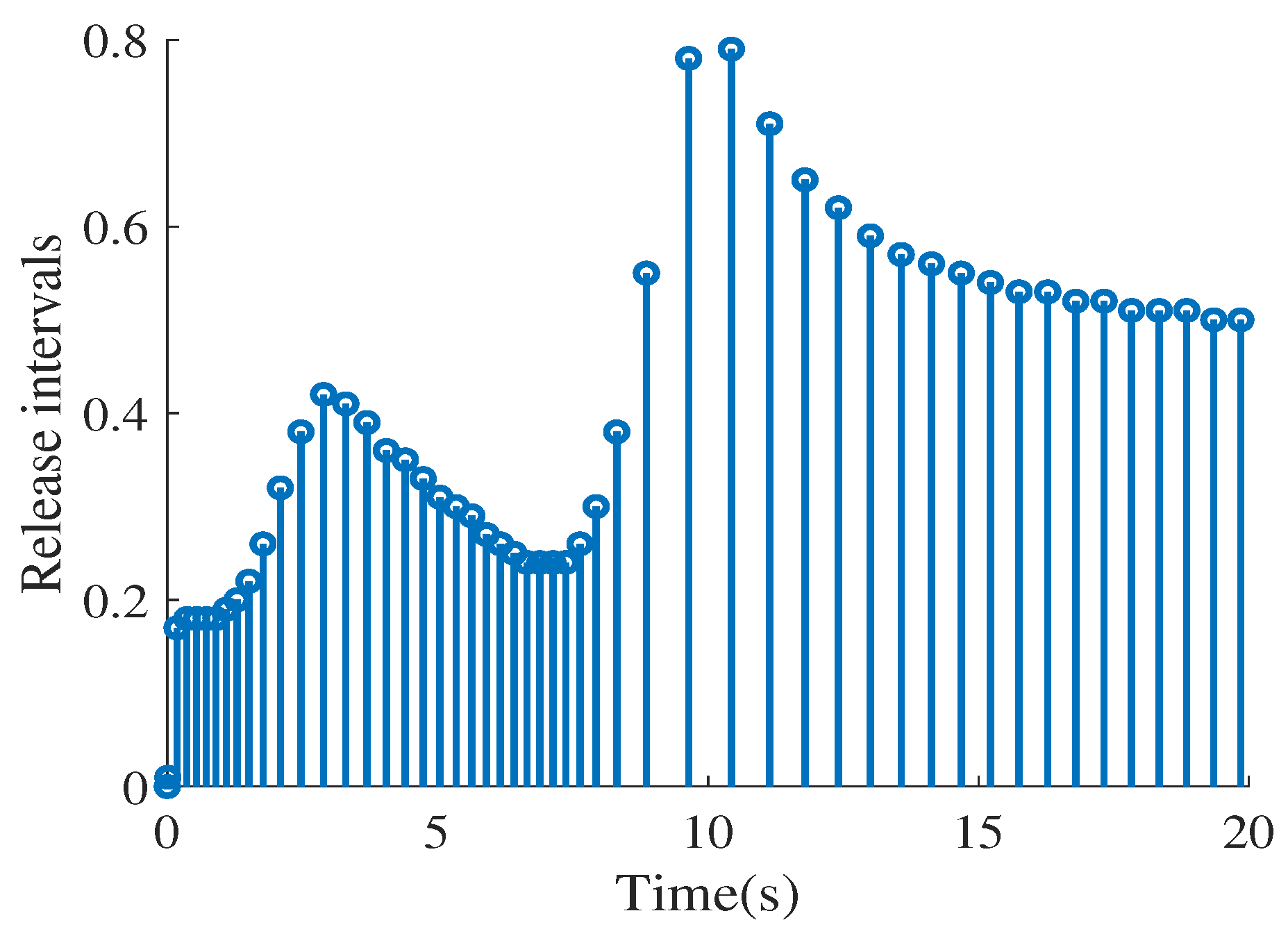
  • An AETS is devised with the primary objective of optimizing communication resource utilization. By strategically setting and adjusting trigger thresholds, AETS effectively curtails redundant data transmissions. Distinguishing itself from the conventional static event-triggered schemes (ETS) outlined in [25,26], AETS exhibits a dynamic capability to adapt its triggering conditions in response to state variations, thereby minimizing unnecessary communication. During periods of system stability, AETS further reduces communication frequency, leading to enhanced savings in communication resources. This adaptability renders AETS a more versatile and practical solution.
  • The SMC method is introduced into a DN-VC system to suppress the effect of an actuator attack. Diverging from conventional SMC strategies [27] that rely on intricate control techniques to address chattering issues, this work presents an SMC law grounded in neural network (NN) technology. This approach not only ensures the attainability of the sliding mode but also effectively mitigates the chattering phenomenon, offering a more streamlined solution.
The remainder of this paper is organized as follows. In Section 2, a distribution network voltage deviation model under actuator attack is established, and an adaptive event-triggered transmission scheme is considered to describe the voltage amplitude deviation. Then the neural network technology is used to estimate the attack signal, and the sliding surface is designed. In Section 3, the main results of the stability analysis, control law design, and controller synthesis of the proposed security event-triggered sliding mode control scheme are given. In what follows, simulation examples are shown to verify the validity of the proposed secure method in Section 4. Finally, Section 5 draws the conclusions of this paper.

2. Problem Formulations

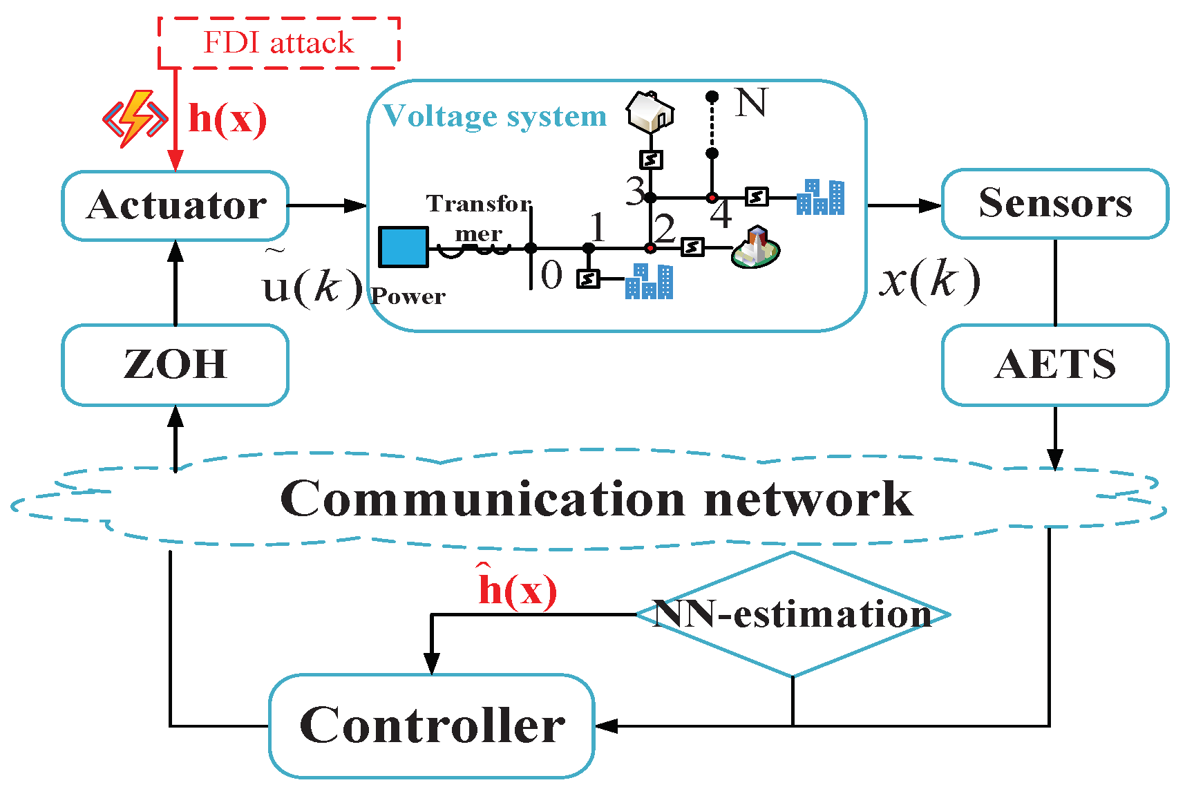
2.1. Voltage Control System under Actuator Attack

Figure 1 illustrates that actuator attacks on the DN-VC system induce voltage fluctuations. Leveraging the robustness of SMC, we devise an optimal sliding mode surface to promptly realign the system’s state and preserve voltage stability. Traditional time-triggered control mechanisms necessitate frequent sampling of voltage deviations across all nodes via the communication network, resulting in resource exhaustion and heightened communication loads. To mitigate this, we employ an AETS to curtail unnecessary communication. Consequently, this paper introduces an event-triggered secure neural network-based sliding mode approach tailored for DN-VC systems.
When the actuator (voltage regulator) of a DN-VC system is attacked by FDI, its control signal will be tampered with, resulting in voltage fluctuation. Suppose the distribution network consists of N nodes, each of which has a voltage deviation Δ V i , ( i = 1 , 2 , , N ) , and each node is equipped with a voltage regulator to regulate the voltage. Consider a dynamic system of voltage deviation under actuator attack
x ( k + 1 ) = A x ( k ) + B u ˜ ( k ) u ˜ ( k ) = u ( k ) + h ( x ( k ) )
where x ( k ) is the state vector containing the voltage deviation of all nodes, that is, x ( k ) = Δ V ( k ) = Δ V 1 ( k ) , Δ V 2 ( k ) , , Δ V N ( k ) T ; A is the system matrix, which describes the coupling relationship between voltages; B is the input matrix that describes the effect of the actuator on the voltage; u ˜ ( k ) is the actual input signal under FDI attacks; u ( k ) is the control input vector of the actuator; and  h ( x ( k ) ) is an arbitrary FDI by attackers. It is assumed that ( A , B ) is controllable.
For convenience, we abbreviate h ( x ( k ) ) to h ( x ) , then the DN-VC system under malicious FDI attacks (1) is transformed into the form of
x ( k + 1 ) = A x ( k ) + B ( u ( k ) + h ( x ) )
where A, B, u ( k ) , and h ( x ) are given in (1).
Remark 1.
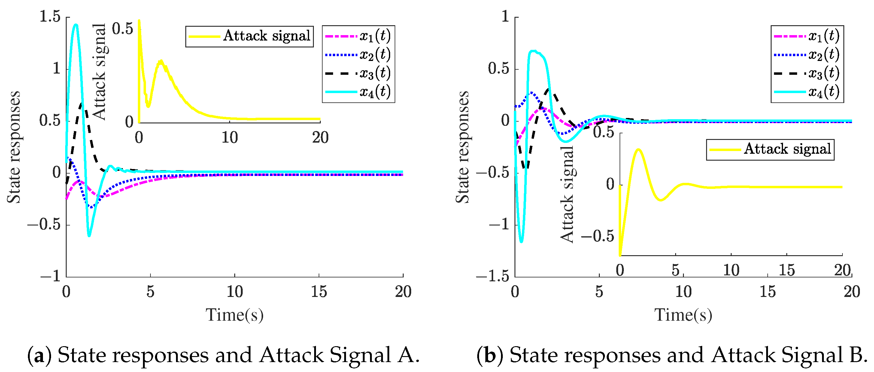
  • It is worth noting that because the neural network technology is used to design the sliding mode control law, we do not make any special assumptions about the attack signal h ( x ) .
  • In fact, currently known cyberattacks do not follow certain rules. However, most studies assume that the attack signal obeys a certain probability distribution or has an upper bound, so the research on network attack in this paper is more practical.

2.2. AETS Scheme and Time-Delays Model

In this subsection, the AETS and its design method are given, and considering network-induced delays, the established closed-loop system is transformed into a time-delay system. For analytical convenience, we assume the following conditions:
  • The sensor samples the data with a time-driven scheme, and the sampling data set is S 1 = { 0 ,   1 ,   2 , } .
  • Whether the sampled data are sent depends on whether the event-triggered condition (see Formula (3)). The set of transmissions that are successfully sent out is S 2 = { k 0 ,   k 1 ,   k 2 , ,   k s } .
  • The controllers and actuators generate their actions in zero-order-hold (ZOH) fashion.
Based on the above assumptions, we construct the following AETS [28]:
k s + 1 = inf k { k > k s | [ x ( k ) x ( k s ) ] T Π [ x ( k ) x ( k s ) ] σ 1 + x ( k s ) x T ( k s ) Π x ( k s ) }
where x ( k ) and x ( k s ) ( s = 0 , 1 , 2 , ) denote the current measured output and the last released one, respectively. k s is the last event triggering time, and k s + 1 is the next triggering time. σ > 0 is the event-triggered parameter, and Π is the corresponding weight matrix to be designed later.
Remark 2.
By introducing system state x ( k s ) into the threshold of the event-triggered condition, the AETS can be dynamically adjusted according to the state of the voltage system. The AETS also has the following characteristics:
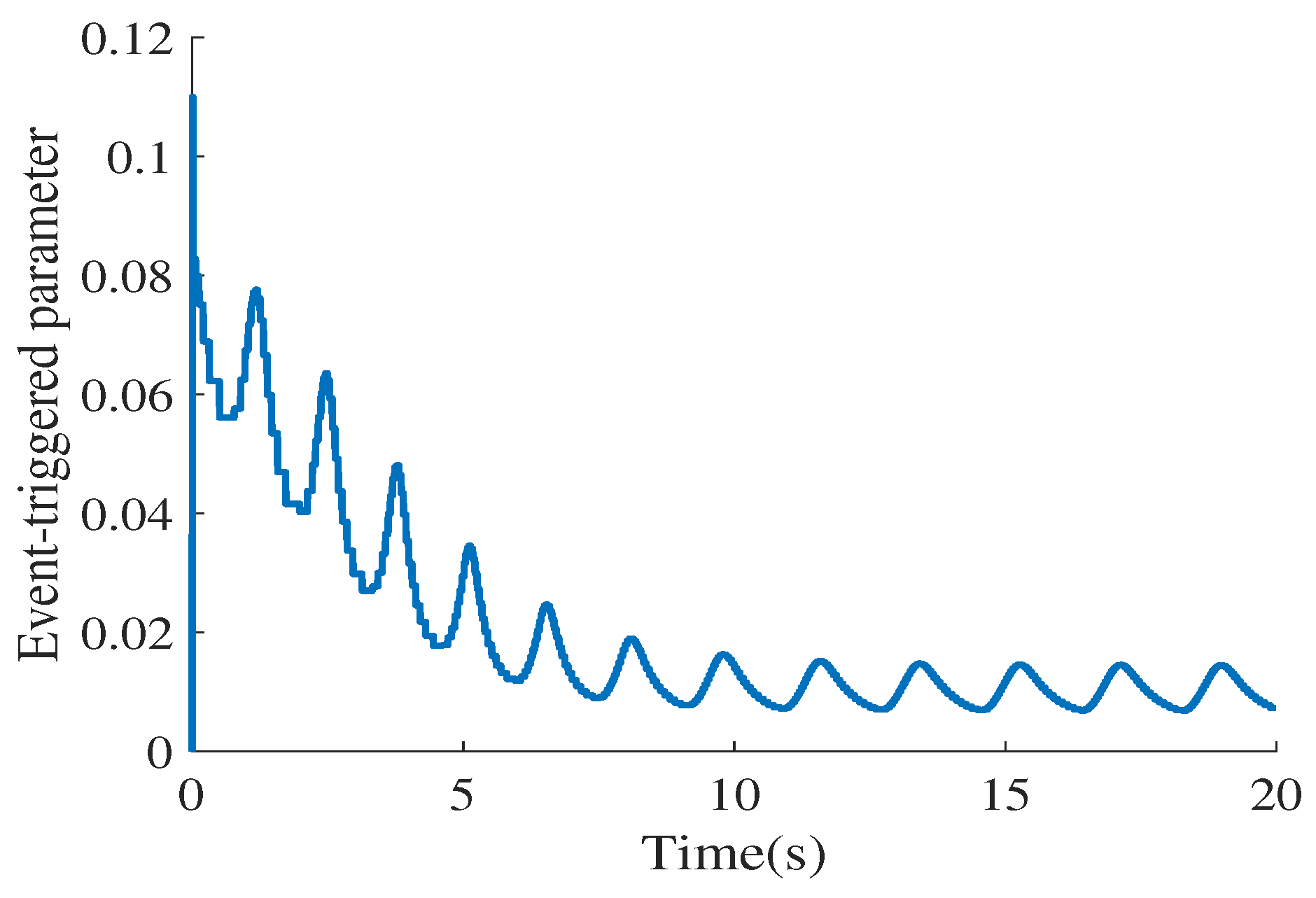
  • The expression of AETS avoids the denominator of the event-triggered threshold function being zero, thereby ensuring that the designed event-triggered function has mathematical significance.
  • By designing an appropriate σ, a better trade-off between control performance and communication efficiency can be achieved.
  • When the system state is unstable, x ( k s ) will increase, resulting in a smaller event-triggered threshold and faster transmission frequency, enhancing the ability to control and regulate the system. Conversely, it can save network resources.
Considering the effect of the network-induced delay, suppose τ k stands for the transmission delay, which is bounded, τ k ( 0 , τ ] , where τ is a positive integer. Considering the transmission delay, trigger state ξ ( k s ) will reach the controller at instants k s + τ k s , where k s + τ k s < k s + 1 + τ k s + 1 , ( s = 1 , 2 , ) .
Similar to [29], we consider the following two cases.
Case A: If k s + τ + 1 k s + 1 + τ k s + 1 1 , define a function τ ( k ) as
τ ( k ) = k k s , k [ k s + τ k s , k s + 1 + τ k s + 1 1 ]
Obviously, τ k s τ ( k ) k s + 1 k s + τ k s + 1 1 1 + τ .
Case B: If k s + τ + 1 < k s + 1 + τ k s + 1 1 , consider [ k s + τ k s , k s + τ ] and [ k s + τ + h , k s + τ + h + 1 ] , where h N and h 1 . Since τ k s τ , there exists the integer d satisfying
k s + d + τ < k s + 1 + τ k s + 1 1 k s + d + τ + 1
Define
Θ 1 = [ k s + τ k s , k s + τ + 1 ) Θ 2 = [ k s + τ + h , k s + τ + h + 1 ) Θ 3 = [ k s + τ + h + d , k s + 1 + τ k s + 1 1 ]
One can obtain that [ k s + τ k s , k s + 1 + τ k s + 1 ] ) = i = 1 3 Θ i .
Define a function
τ ( k ) = k k s , k Θ 1 k k s h , k Θ 2 k k s d , k Θ 3
Then, we can obtain
τ k s τ ( k ) 1 + τ = τ ¯ , k Θ 1 τ k s τ ( k ) τ ¯ , k Θ 2 τ k s τ ( k ) τ ¯ , k Θ 3
In Case A, define the vector χ ( k ) = 0 . In Case B, define
χ ( k ) = 0 , k Θ 1 x ( k s ) x ( k s + h ) , k Θ 2 x ( k s ) x ( k s + d ) , k Θ 3
Based on (7), it is easy to obtain
0 τ k s τ ( k ) τ + 1 τ ¯
From AETS (3) and the definition of χ ( k ) (8), when k [ k s + τ k s , k s + 1 + τ k s + 1 1 ] , the following condition holds:
χ T ( k ) Π χ ( k ) σ 1 + x ( k s ) x T ( k τ ( k ) ) Π x ( k τ ( k ) )
Based on (6) and (9), (2) can be rewritten as follows:
x ( k + 1 ) = A x ( k ) + B K x ( k τ ( k ) ) + B K χ ( k ) + B h ( x ) s u b j e c t t o : ( 8 )
for k [ k s + τ k s , k s + 1 + τ k s + 1 1 ] , here, K is the feedback controller’s gain, and τ ( k ) [ 0 , τ ¯ ] is the network-induced delay with τ ¯ τ + 1 .

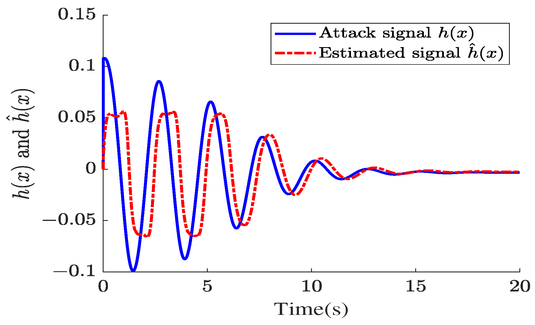
2.3. Neural Network-Based Estimation of Attack Signal

In this subsection, in order to design a good sliding mode control law, we apply an NN technique to approach the attack signal h ( x ) as
h ( x ) = Q T L ( x ) + γ ( x ) , x Λ R r
where Λ expresses a compact set, Q R r × m is an ideal constant weight matrix, r is the number of NN nodes, and  γ ( x ) denotes the NN approximation error in which γ ( · ) γ ¯ . The basis function is
L ( x ) = l 1 ( x ) l 2 ( x ) l r ( x ) T
which satisfies L ( · ) L m a x in which L m a x is a positive constant. l j ( x ) can be represented as
l j ( ξ ) = e x p ( x p j 2 v j )
where p j and v j are the center and width of function l j ( x ) , respectively, and  p j = p j 1 p j 2 p j 3 T .
Therefore, the estimation h ^ ( x ) of the deception attack signal h ( x ) is constructed as
h ^ ( x ) = Q ^ T ( k ) L ( x )
where Q ^ ( k ) is the estimation of Q . Then, the adaptive law Q ^ is designed as follows:
Q ^ ( k + 1 ) = α Q ^ ( k ) + Q ^ ( k ) β ζ ( k ) x T ( k ) W T ,
where α > 0 and β > 0 are two constants, W R n × m is an adjustment parameter, and ζ ( k ) = L ( x ) / ( 1 + L ( x ) 2 W x ( k ) 2 ) .
Remark 3.
Generally, sliding mode controllers need to be designed based on the upper bound of the attack signal, which can cause chattering. In this paper, we use NN technology to estimate the attack signal and design a sliding mode controller based on the estimated value, which can effectively reduce the occurrence of chattering.

2.4. Design of Sliding Mode Surface

The key idea of the security control scheme in this paper is divided into two parts. First, an equivalent controller u e ( k ) is designed to ensure that the nominal system is stable without attacks. Then, a switching controller u s ( k ) is designed to suppress actuator attacks. So the secure sliding mode control structure is given by
u ( k ) = u e ( k ) + u s ( k )
where u e ( k ) is the equivalent controller and u s ( k ) is the switching controller.
To design the controller, we firstly design a sliding mode surface as follows:
M ( k ) = G x ( k ) G ( A + B K ) x ( k 1 )
where M ( k ) is the sliding mode surface and  G B is nonsingular.
Remark 4.
It is obvious that G is the sliding gain that can be computed using the LQR method based on the proper selection of Q and R matrices [23]. In this paper, we choose Q 0 , R > 0 , and P > 0 to be the solution of the Riccati equation: P = A T P A A T P B ( R + B T P B ) 1 B T P A + Q and G = B T P .
When entering the ideal sliding mode, M ( k ) satisfies M ( k + 1 ) = M ( k ) = 0 , that is,
M ( k + 1 ) = G x ( k + 1 ) G ( A + B K ) x ( k ) = G [ A x ( k ) + B u ( k ) + B h ( x ) ] G ( A + B K ) x ( k ) = G B u ( k ) + G B h ( x ) G B K x ( k )
From the above equation, the secure sliding mode controller is derived as
u ( k ) = u e ( k ) + u s ( k ) = K x ( k ) h ( x )
Under the AETS, the secure sliding mode controller can be rewritten as
u ( k ) = u e ( k ) + u s ( k ) = K x ( k s ) h ( x ) = K x ( k τ ( k ) ) + K χ ( k ) h ( x )
Obviously, when u s ( k ) = h ( x ) , the voltage control system under the actuator attack (10) is rewritten as the nominal system as follows:
x ( k + 1 ) = A x ( k ) + B K x ( k τ ( k ) ) + B K χ ( k )
In order to obtain the main results of this paper, the following lemma is given.
Lemma 1.
(Discrete Jensen inequality) Given positive integers λ 1 and λ 2 meeting the requirements of 1 λ 1 λ 2 , then for any constant matrix 𝟊 R n × n , the following inequality holds [22]:
( λ 2 λ 1 ) i = λ 1 λ 2 1 λ T ( i ) 𝟊 λ ( i ) i = λ 1 λ 2 1 λ T ( i ) 𝟊 i = λ 1 λ 2 1 λ ( i )

3. Main Results

In this section, we provide the stability analysis, equivalent controller design, and sliding mode switching controller design for event-triggered sliding mode control systems.

3.1. Asymptotical Stability Analysis

Theorem 1 proves the stability of closed-loop DN-VC control system based on the event-triggered sliding mode control strategy under an actuator attack.
Theorem 1.
If there are some given positive scalars σ, τ ¯ , a matrix K and symmetric positive definite matrices P ¯ , Q ¯ , R ¯ , and Π with appropriate dimensions satisfying
Ω = Ω 11 Ω 12 Ω 22 < 0
where
  • Ω 11 = [ ( 1 , 1 ) = P ¯ ( A I ) + ( A I ) T P ¯ + Q ¯ R ¯ ,
  • ( 1 , 2 ) = 2 P ¯ B K + R ¯ , ( 1 , 4 ) = 2 P ¯ B K ,
  • ( 2 , 1 ) = R ¯ , ( 2 , 2 ) = 2 R ¯ + σ Π , ( 2 , 3 ) = R ¯ ,
  • ( 3 , 2 ) = R ¯ , ( 3 , 3 ) = R ¯ Q ¯ , ( 4 , 4 ) = Π ]
  • Ω 12 = Γ T P ¯ τ ¯ Γ T R ¯
  • with Γ = A I B K 0 B K ,
  • Ω 22 = d i a g { P ¯ , R ¯ } .
then the DN-VC system with actuator attacks (2) is asymptotically stable under AETS (3) and the secure sliding mode controller (16).
Proof. 
We choose the Lyapunov–Krasovskii functional as follows:
V ( k , x k ) = i = 1 3 V i ( k , x k )
where
  • V 1 ( k , x k ) = x T ( k ) P ¯ x ( k )
  • V 2 ( k , x k ) = j = k τ ¯ k 1 x T ( j ) Q ¯ x ( j )
  • V 3 ( k , x k ) = τ ¯ τ ¯ + 1 0 s = k + j 1 k 1 ξ T ( s ) R ¯ ξ ( s )
where ξ ( k ) = x ( k + 1 ) x ( k ) and Δ V ( k ) = V ( k + 1 , x k + 1 ) V ( k , x k ) .
Then, calculating the differences of V i ( k ) ( i = 1 , 2 , 3 ) along the solution of sliding mode dynamics, one obtains
Δ V 1 ( k , x k ) = x T ( k + 1 ) P ¯ x ( k + 1 ) x T ( k ) P ¯ x ( k ) x T ( k ) [ P ¯ ( A I ) + ( A I ) T P ¯ ] x ( k ) + 2 x T ( k ) P ¯ B K χ ( k ) + μ T ( k ) Γ T P ¯ Γ μ ( k ) + 2 x T ( k ) P ¯ B K x ( k τ ( k ) )
where μ ( k ) = c o l { x ( k ) , x ( k τ ( k ) ) , x ( k τ ¯ ) , χ ( k ) } , Γ = A I B K 0 B K .
Δ V 2 ( k , x k ) x T ( k ) Q ¯ x ( k ) x T ( k τ ¯ ) Q ¯ x ( k τ ¯ )
Δ V 3 ( k , x k ) τ ¯ 2 ξ T ( k ) R ¯ ξ ( k ) τ ¯ i = k τ ¯ k 1 ξ T ( i ) R ¯ ξ ( i ) τ ¯ 2 μ T ( k ) Γ T R ¯ Γ μ ( k ) τ ¯ i = k τ ¯ k 1 ξ T ( i ) R ¯ ξ ( i )
Using the discrete Jensen inequality (22), there exists
τ ¯ i = k τ ¯ k 1 ξ T ( i ) R ¯ ξ ( i ) = τ ¯ i = k τ ( k ) k 1 ξ T ( i ) R ¯ ξ ( i ) τ ¯ i = k τ ¯ k τ ( k ) 1 ξ T ( i ) R ¯ ξ ( i ) [ x ( k ) x ( k τ ( k ) ) ] T R ¯ [ x ( k ) x ( k τ ( k ) ) ] [ x ( k τ ( k ) ) x ( k τ ¯ ) ] T R ¯ [ x ( k τ ( k ) ) x ( k τ ¯ ) ]
By combining (25)–(28) and applying χ T ( k ) Π χ ( k ) σ x T ( k τ ( k ) ) Π x ( k τ ( k ) ) , the following relation is achieved:
Δ V ( k ) μ T ( k ) Ω μ ( k )
where μ ( k ) = c o l { x ( k ) , x ( k τ ( k ) ) , x ( k τ ¯ ) , χ ( k ) } , Ω is given in (23).
Based on the above analysis, it can be concluded that if the LMI (23) holds, then system (21) is asymptotically stable, which means that the DN-VC system is stable under the actuator attack under the sliding mode control strategy. The proof is completed. □
Remark 5.
It is worth noting that in Theorem 1, we can easily obtain the conditions that make the closed-loop system (21) asymptotically stable. However, the state feedback controller gain K is not obtained. Therefore, Theorem 2 synthesizes the state feedback controller gain through some matrix inequality operations.
Theorem 2.
Given positive scalars σ, τ ¯ , if there are symmetric positive definite matrices X, P ¯ ^ , Q ¯ ^ , R ¯ ^ , Π ^ , and Y with appropriate dimensions satisfying
Ω ^ 11 Ω ^ 12 Ω ^ 22 < 0
where
  • Ω ^ 11 = [ ( 1 , 1 ) = ( A I ) X + X ( A I ) T + Q ¯ ^ R ¯ ^ ,
  • ( 1 , 2 ) = 2 B Y + R ¯ ^ , ( 1 , 4 ) = 2 B Y ,
  • ( 2 , 1 ) = R ¯ ^ , ( 2 , 2 ) = 2 R ¯ ^ + σ Π ^ , ( 2 , 3 ) = R ¯ ^ ,
  • ( 3 , 2 ) = R ¯ ^ , ( 3 , 3 ) = R ¯ ^ Q ¯ ^ , ( 4 , 4 ) = Π ^ ]
  • Ω 12 = Γ ^ T τ ¯ Γ ^ T
    with Γ ^ = A X X B Y 0 B Y ,
  • with Γ ^ = A X X B Y 0 B Y ,
  • Ω ^ 22 = d i a g { X , R ¯ ^ 2 X } .
then the equivalent event-triggered feedback controller is calculated by
u e ( k ) = Y X 1 x ( k s )
Proof. 
Define X = ( P ¯ ) 1 , Y = K X , P ¯ ^ = X P ¯ X , Q ¯ ^ = X Q ¯ X , R ¯ ^ = X R ¯ X , and  Π ¯ ^ = X Π ¯ X . Pre- and postmultiplying both sides of matrix inequality (23) with d i a g X X X X X R ¯ 1 and using the fact that X R ¯ ^ X R ¯ ^ 2 X , we can arrive at the desired results.    □

3.2. Design of Sliding Mode Switching Controller

Theorem 1 proved the stability of the closed-loop control system under actuator attacks triggered by events under the sliding mode control strategy. Theorem 2 gave the traditional feedback controller gain K. Therefore, Theorem 3 designs the switch controller u s ( k ) to complete the design of the adaptive event-triggered sliding mode controller u ( k ) = u e ( k ) + u s ( k ) .
Theorem 3.
In order to ensure the stability of DN-VC system (2) subject to actuator attacks h ( x ) under AETS (3), the corresponding switching control law can be chosen as
u s ( k ) = ( G B ) 1 [ ϕ M ( k ) s g n ( M ( k ) ) ] ( h ^ ( x ) + κ )
where 0 < ϕ < 1 is a constant, h ^ ( x ) is the estimated value of the attack signal h ( x ) , which is designed in (14), and κ is a given positive scalar.
Proof. 
Selecting the Lyapunov function as
V s ( k ) = M T ( k ) M ( k )
Δ V s ( k ) = M T ( k + 1 ) M ( k + 1 ) M T ( k ) M ( k ) = [ G x ( k + 1 ) G ( A + B K ) x ( k ) ] T [ G x ( k + 1 ) G ( A + B K ) x ( k ) ] M T ( k ) M ( k ) = [ G ( ( A + B K ) x ( k ) + B u s ( k ) + B h ( x ) ) G ( A + B K ) x ( k ) ] T [ G ( ( A + B K ) x ( k ) + B u s ( k ) + B h ( x ) ) G ( A + B K ) x ( k ) ] M T ( k ) M ( k ) = { [ ϕ M ( k ) s g n ( M ( k ) ) ] + G B ( h ( x ) ( h ^ ( x ) + κ ) ) } T { [ ϕ M ( k ) s g n ( M ( k ) ) ] + G B ( h ( x ) ( h ^ ( x ) + κ ) ) } M T ( k ) M ( k ) [ ϕ M ( k ) s g n ( M ( k ) ) ] T [ ϕ M ( k ) s g n ( M ( k ) ) ] M T ( k ) M ( k ) ( ϕ 2 1 ) M ( k ) 0
This completes the proof. □
Remark 6.
It is worth noting that when the state of the DN-VC system deviates from the sliding mode surface due to actuator attacks, the switch controller u s ( k ) dynamically adjusts the control input according to the change in system state to maintain the stability and accuracy of the sliding mode motion. Even in the face of continuous impact from actuator attacks, the switch controller can maintain effective control of the system through its variable structure characteristics.
Remark 7.
For a better understanding of the design of the switching controller and the derivation of (34), we give the following explanation:
  • The positive scalar κ in the switching controller is used to achieve the scaling in (34).
  • Since the constant ϕ in the switching controller is 0 < ϕ < 1 , therefore, ( ϕ 2 1 ) < 0 , so Δ V s ( k ) < 0 in (34).
Remark 8.
In fact, Theorem 1 proves the stability of the closed-loop DN-VC control system based on the event-triggered sliding mode control strategy under actuator attacks. Consequently, Theorem 2 subsequently presents the event-triggered feedback controller gain K, and Theorem 3 designs the sliding mode switching controller u s ( k ) , completing the design of the comprehensive security controller u ( k ) . In summary, Theorems 1–3 first demonstrate the stability of the system under the proposed security control strategy and then proceed to design the security control strategy.
Theorem 4.
Consider the secure DN-VC system (2) subject to actuator attacks h ( x ) . The sliding mode secure event-triggered control scheme can be designed as
u ( k ) = Y X 1 x ( k s ) + { ( G B ) 1 [ ϕ M ( k ) s g n ( M ( k ) ) ] ( h ^ ( x ) + κ ) }
Proof. 
Theorem 2 obtains the event-triggered controller u e ( k ) = K x ( k s ) = Y X 1 x ( k s ) . Theorem 3 obtains the sliding mode switching controller u s ( k ) = ( G B ) 1 [ ϕ M ( k ) s g n ( M ( k ) ) ] ( h ^ ( x ) + κ ) . So the comprehensive security sliding mode controller u ( k ) = u e ( k ) + u s ( k ) = Y X 1 x ( k s ) + { ( G B ) 1 [ ϕ M ( k ) s g n ( M ( k ) ) ] ( h ^ ( x ) + κ ) } (35) can be obtained by Theorems 1–3.    □
At last, the following Algorithm 1 is presented to achieve a better understand of the technical line of the proposed security solution.
Algorithm 1 Technical line of the proposed security solution.
1:
Establishing a voltage deviation model and considering actuator attacks to obtain system (2). Go to 2.
2:
Design AETS and considering the network-induced delay probability distribution, a delay state space model (10) is established, and go to 3.
3:
NN technology is used to estimate the actuator attack signal (14) in order to reduce chattering. Go to 4.
4:
The sliding mode surface (17) is designed, which is the basis for designing sliding mode control law. Go to 4.
5:
Give some given scalars σ and  τ ¯ .
6:
Solve LMI (30) and find the equivalent controller gain K using Matlab LMI toolbox. If there exists such a solution K, go to 7; Else, go to 5.
7:
For given ϕ , κ and h ^ ( x ) , design the SMC law (32). Then, go to 8.
8:
Calculate the secure controller u ( k ) according to Theorems 1–3.

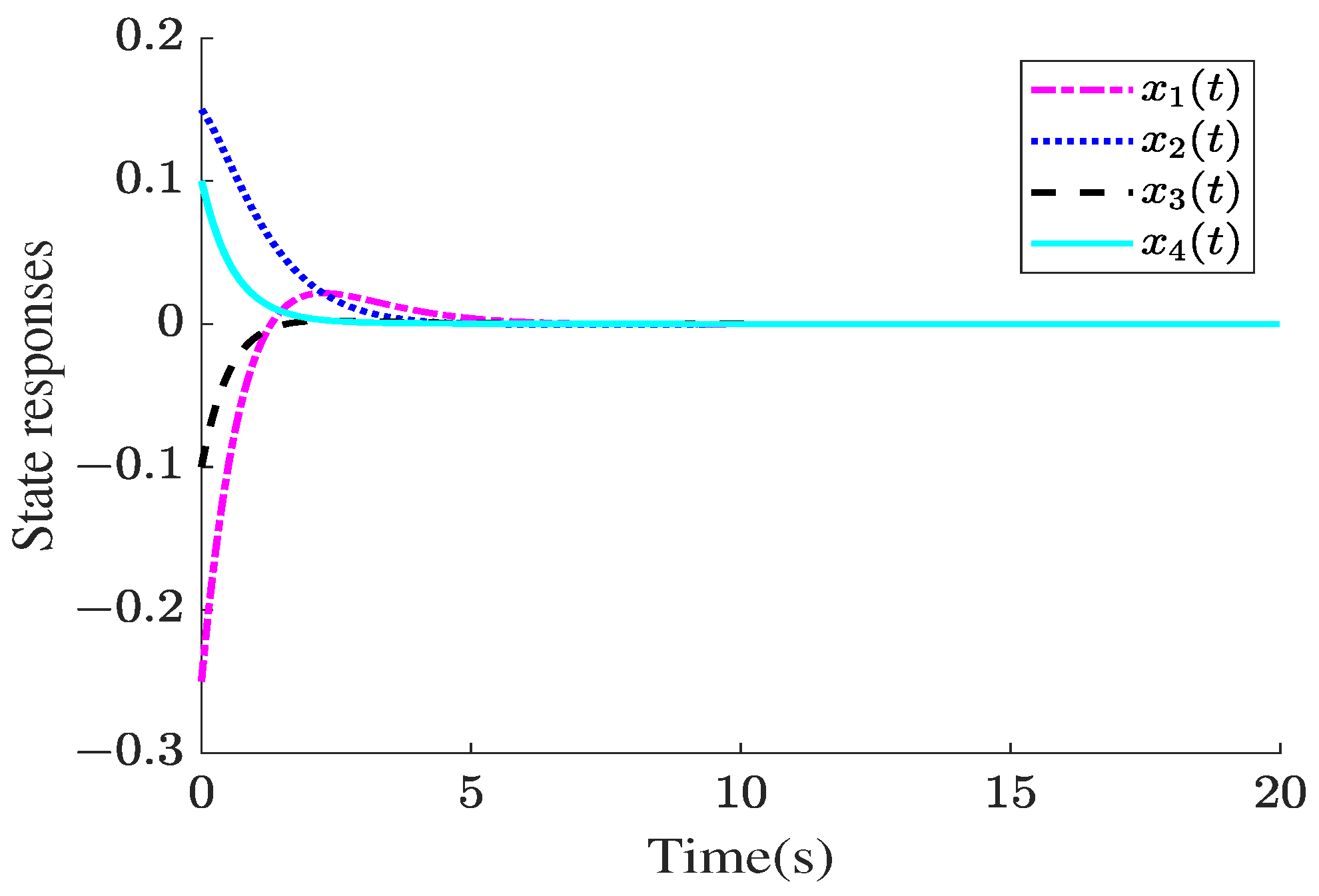
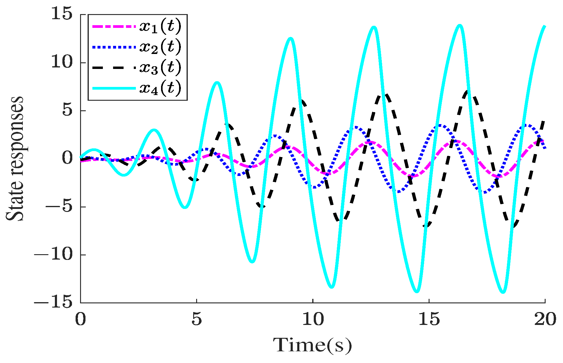
4. Illustrative Examples

In this section, we give three examples to prove the availability of event-triggered sliding mode controllers in discrete-time systems. The simulation platform is constructed with Matlab (2023b), and all software programs are run on a PC with 2.40 GHz Intel(R) Core(TM) i5-9300H CPU , 8 GRAM and Windows 11 64-bit Ultimate.
Parameter and state matrix setups: As shown in Figure 2, we adopt a four-node voltage topological system model.
According to our defined state variable x ( k ) = Δ V 1 ( k ) , Δ V 2 ( k ) , , Δ V N ( k ) T , where each Δ V i represents the voltage deviation of a node and the input variable u ( k ) is the input of the voltage regulator. We set specific parameters for A and B matrices.
A = 1.0000 1.0000 0.0000 0.0000 0.0000 1.000 1.0000 0.0000 0.0000 0.0000 1.0000 1.0000 0.0000 0.0000 0.0000 1.0000 ,
B = 0.1000 0.1500 0.2000 25.0000 T .
Let τ ¯ = 0.01 , σ = 0.11 . According to (30) and using the Matlab LMI toolbox, we can obtain
K = 0.0005 0.0013 0.0096 0.0103
Π = 10 9 × 0.4222 0.0020 0.0020 0.0008 0.0020 0.4127 0.0006 0.0028 0.0020 0.0006 0.4132 0.0064 0.0008 0.0028 0.0064 0.4129
In addition, we set Q = 0.1 and R is a four-dimensional subdiagonal matrix, so we can calculate that G = 84.4538 357.6397 536.2088 291.3913 .
Secure control design: Assume that the malicious FDI attack signal is selected as
h ( x ) = 0.9 t a n h ( x 2 ( k ) ) + 0.1 x 1 ( k ) ( 1 + x 1 2 ( k ) ) + 0.01 s i n ( x 1 ( k ) )
Suppose that the NN consists of five nodes. Assuming the compact set Λ is [ 2 , 2 ] 5 , in which the centers l j are uniformly distributed in Λ and the widths are v j = 4 with j < 5 > . The initial value of Q ^ ( 0 ) = 0 5 × 1 . Set α = 2 , β = 0.05 . Then, we can obtain the update law of Q ^ ( k ) as
Q ^ ( k + 1 ) = 2 Q ^ ( k ) + Q ^ ( k ) 0.05 ζ ( k ) x T ( k ) W T ,
by defining W = 1 1 1 1 .
By defining ϕ = 0.01 and κ = 0.005 , we then obtain that
u s ( k ) = 0.14 3 M ( k ) s g n ( M ( k ) ) ( h ^ ( x ) + 0.005 )
Based on the above calculations, the secure control
u ( k ) = 0.0005 0.0013 0.0096 0.0103 x ( k s ) + 0.14 3 M ( k ) s g n ( M ( k ) ) ( h ^ ( x ) + 0.005 )
Finally, the sampling period is given by h = 0.01 s , and the total simulation time is set as T = 20 s .
Based on the above setups, we can obtain the following simulation results.
Results comparisons and analysis
In this subsection, the following three simulation results are compared in order to highlight the effectiveness of the proposed sliding mode control scheme. Part A shows the traditional control case with u e ( k ) = K x ( k s ) in an attack-free scenario. For comparison, Part B shows the malicious effects caused by actuator attacks without the sliding mode secure scheme. In order to show the effectiveness of the proposed secure control approach, Part C corrects the actuator attack signal with the designed SMC law u s ( k ) = ( G B ) 1 [ ϕ M ( k ) s g n ( M ( k ) ) ] ( h ^ ( x ) + κ ) .
Part A: Attack-free case under  u e ( k )
In this case, we assume that no actuator attacks occurred and no additional auxiliary secure design is performed on the controller, which means the controller is only given by u e ( k ) = K x ( k s ) . The state response of the DN-VC system is shown in Figure 3, and the released intervals are shown in Figure 4.
It can be clearly seen from Figure 3 that when the actuator is not attacked, the voltage deviation value of the voltage control system will soon reach 0, which shows the effectiveness of the original controller u e ( k ) . In addition, it can be seen from Figure 4 that the total number of packets transmitted is 51. This implies that the event-triggered transmission scheme is effective.
Part B: Actuator attacks under  u e ( k )
When the actuator of the voltage system is injected with a malicious attack signal h ( x ) = 0.9 t a n h ( x 2 ( k ) ) + 0.1 x 1 ( k ) / ( 1 + x 1 2 ( k ) ) + 0.01 s i n ( x 1 ( k ) ) , the controller, without additional auxiliary design, still uses the traditional event-triggered controller u e ( k ) to implement it, and the actuator will produce erroneous actions. This is evident from Figure 5, where system stability is compromised. Furthermore, Figure 6 reveals an increase in data transmission frequency compared to Figure 3. Notably, Figure 7 demonstrates the adaptive adjustment of the event-triggered threshold in response to system state changes. However, the control signal output by the controller, as depicted in Figure 8, indicates that the traditional event-triggered controller fails to maintain the desired stability performance of the control system.
Part C: Actuator attacks under  u e ( k ) + u s ( k )
Finally, when there are actuator attacks on the DN-VC system, we use the proposed secure event-triggered sliding mode controller u ( k ) = Y X 1 x ( k s ) + { ( G B ) 1 [ ϕ M ( k ) s g n ( M ( k ) ) ] ( h ^ ( x ) + κ ) } to verify the effectiveness of the method. Figure 9 shows that the voltage error of the system gradually approaches 0 under the action of the designed secure controller, indicating that the AETC sliding mode control strategy can achieve good stability. Figure 10 demonstrates the effectiveness of the event-triggered mechanism and, compared with Figure 6, it can be seen that the AETC can schedule communication resources in a more efficient manner. Figure 11 shows the change in the event trigger threshold. Figure 12 shows the approximation effect of NN technology on the attack signal.
Evidently, Part A underscores the capability of the feedback controller u e ( k ) as formulated in Theorem 2 to ensure system stability when no attacks are present. The juxtaposition of Part B and Part C highlights the efficacy of the comprehensive security sliding mode control law u ( k ) derived from Theorem 3 in attenuating the detrimental effects of actuator attacks on the DN-VC system. Additionally, these three illustrative cases collectively emphasize the notable benefits of event-triggered approaches in conserving communication resources.
Remark 9.
In order to validate the superiority of the adaptive event-triggered sliding mode control strategy proposed in this paper, we selected two attack signals, namely, Signal A and Signal B, for testing. S i g n a l A = 0.5 t a n h ( x 1 ( k ) ) x 1 ( k ) ( 1 + x 1 2 ( k ) ) s i n ( x 1 ( k ) ) and S i g n a l B = 0.8 t a n h ( x 1 ( k ) ) + x 1 ( k ) ( 1 + x 1 2 ( k ) ) + s i n ( x 1 ( k ) ) . The obtained results are presented in Figure 13 as follows: Figure 13a depicts the state of the voltage system under the attack of Signal A, with the yellow curve representing the attack signal; Figure 13b illustrates the state of the voltage system under the attack of Signal B, with the yellow curve indicating the corresponding attack signal. We can observe that under the influence of different attack signals, the security control strategy we proposed is able to promptly stabilize the voltage control system.

5. Conclusions

The secure control of distribution network voltage control systems under actuator attacks was studied. Firstly, a voltage deviation model under actuator attacks was established. Secondly, an adaptive event-triggered transmission scheme was proposed to conserve network communication resources more efficiently under limited bandwidth. Then, a sliding mode control strategy was devised to mitigate actuator attacks, and neural network technology was utilized to approximate the attack signals in order to reduce chattering phenomena. By leveraging the Lyapunov–Krasovskii method and solving a set of linear matrix inequalities, stability criteria and stabilization methods for the voltage control system were obtained. Finally, the effectiveness of the secure control method was validated through simulation examples.
However, the voltage control model presented in this paper does not take into account many complex factors in distribution networks, such as nonlinearity and unbalanced loads. As a result, our future research objective is to develop a comprehensive control strategy that considers a wider range of factors, including load forecasting, distributed energy resource scheduling, and so on.

Funding

This research received no external funding.

Data Availability Statement

The data presented in this study are available in this article.

Conflicts of Interest

The authors declare no conflicts of interest.

References

  1. Murray, W.; Adonis, M.; Raji, A. Voltage control in future electrical distribution networks. Renew. Sustain. Energy Rev. 2021, 146, 111100. [Google Scholar] [CrossRef]
  2. Nandhini, E.; Sivaprakasam, A. A review of various control strategies based on space vector pulse width modulation for the voltage source inverter. IETE J. Res. 2022, 68, 3187–3201. [Google Scholar] [CrossRef]
  3. Baleboina, G.M.; Mageshvaran, R. A survey on voltage stability indices for power system transmission and distribution systems. Front. Energy Res. 2023, 11, 1159410. [Google Scholar] [CrossRef]
  4. Heidary, J.; Gheisarnejad, M.; Rastegar, H.; Khooban, M.H. Survey on microgrids frequency regulation: Modeling and control systems. Electr. Power Syst. Res. 2022, 213, 108719. [Google Scholar] [CrossRef]
  5. Kim, S.J.; Park, K.J.; Lu, C. A survey on network security for cyber–physical systems: From threats to resilient design. IEEE Commun. Surv. Tutor. 2022, 24, 1534–1573. [Google Scholar] [CrossRef]
  6. Aoufi, S.; Derhab, A.; Guerroumi, M. Survey of false data injection in smart power grid: Attacks, countermeasures and challenges. J. Inf. Secur. Appl. 2020, 54, 102518. [Google Scholar] [CrossRef]
  7. Reda, H.T.; Anwar, A.; Mahmood, A. Comprehensive survey and taxonomies of false data injection attacks in smart grids: Attack models, targets, and impacts. Renew. Sustain. Energy Rev. 2022, 163, 112423. [Google Scholar] [CrossRef]
  8. Tufail, S.; Parvez, I.; Batool, S.; Sarwat, A. A survey on cybersecurity challenges, detection, and mitigation techniques for the smart grid. Energies 2021, 14, 5894. [Google Scholar] [CrossRef]
  9. Duo, W.; Zhou, M.; Abusorrah, A. A survey of cyber attacks on cyber physical systems: Recent advances and challenges. IEEE/CAA J. Autom. Sin. 2022, 9, 784–800. [Google Scholar] [CrossRef]
  10. Gunduz, M.Z.; Das, R. Cyber-security on smart grid: Threats and potential solutions. Comput. Netw. 2020, 169, 107094. [Google Scholar] [CrossRef]
  11. Wu, Y.; Wei, D.; Feng, J. Network attacks detection methods based on deep learning techniques:A survey. Secur. Commun. Netw. 2020, 2020, 8872923. [Google Scholar] [CrossRef]
  12. Wang, S.; Bi, S.; Zhang, Y. Locational detection of the false data injection attack in a smart grid: A multilabel classification approach. IEEE Internet Things J. 2020, 7, 8218–8227. [Google Scholar] [CrossRef]
  13. Lu, K.; Wu, Z. Constrained-differential-evolution-based stealthy sparse cyber-attack and countermeasure in an AC smart grid. IEEE Trans. Ind. Inform. 2021, 18, 5275–5285. [Google Scholar] [CrossRef]
  14. Shi, J.; Liu, S.; Chen, B.; Yu, L. Distributed data-driven intrusion detection for sparse stealthy FDI attacks in smart grids. IEEE Trans. Circuits Syst. II Express Briefs 2020, 68, 993–997. [Google Scholar] [CrossRef]
  15. Ijaz, S.; Galea, M.; Hamayun, M.T.; Ijaz, H.; Javaid, U. A new output integral sliding mode fault-tolerant control and fault estimation scheme for uncertain systems. IEEE Trans. Autom. Sci. Eng. 2023; early access. [Google Scholar] [CrossRef]
  16. Huang, S.; Xiong, L.; Zhou, Y.; Gao, F.; Jia, Q.; Li, X.; Li, X.; Wang, Z.; Khan, M.W. Distributed Predefined-Time Control for Power System with Time Delay and Input Saturation. IEEE Trans. Power Syst. 2024; early access. [Google Scholar] [CrossRef]
  17. Reda, H.T.; Anwar, A.; Mahmood, A.; Chilamkurti, N. Data-driven approach for state prediction and detection of false data injection attacks in smart grid. J. Mod. Power Syst. Clean Energy 2022, 11, 455–467. [Google Scholar] [CrossRef]
  18. Kang, W.; Chen, M.; Guan, Y.; Tang, L.; Guerrero, J.M. Distributed event-triggered optimal control method for heterogeneous energy storage systems in smart grid. IEEE Trans. Sustain. Energy 2022, 13, 1944–1956. [Google Scholar] [CrossRef]
  19. Ge, P.; Chen, B.; Teng, F. Event-triggered distributed model predictive control for resilient voltage control of an islanded microgrid. Int. J. Robust Nonlinear Control 2021, 31, 1979–2000. [Google Scholar] [CrossRef]
  20. Ding, S.; Xie, X.; Liu, Y. Event-triggered static/dynamic feedback control for discrete-time linear systems. Inf. Sci. 2020, 524, 33–45. [Google Scholar] [CrossRef]
  21. Behera, A.K.; Bandyopadhyay, B.; Cucuzzella, M.; Ferrara, A. A survey on event-triggered sliding mode control. IEEE J. Emerg. Sel. Top. Ind. Electron. 2021, 2, 206–217. [Google Scholar] [CrossRef]
  22. Ge, X.; Han, Q.; Ding, L.; Wang, Y. Dynamic event-triggered distributed coordination control and its applications: A survey of trends and techniques. IEEE Trans. Syst. Man Cybern. Syst. 2020, 50, 3112–3125. [Google Scholar] [CrossRef]
  23. Wang, X.; Sun, J.; Wang, G.; Allgöwer, F.; Chen, J. Data-driven control of distributed event-triggered network systems. IEEE/CAA J. Autom. Sin. 2023, 10, 351–364. [Google Scholar] [CrossRef]
  24. Wu, J.; Peng, C.; Yang, H.; Wang, Y. Recent advances in event-triggered security control of networked systems: A survey. Int. J. Syst. Sci. 2022, 53, 2624–2643. [Google Scholar] [CrossRef]
  25. Li, M.; Long, Y.; Li, T.; Chen, C. Consensus of linear multi-agent systems by distributed event-triggered strategy with designable minimum inter-event time. Inf. Sci. 2022, 609, 644–659. [Google Scholar] [CrossRef]
  26. Inomoto, R.S.; de Almeida Monteiro, J.B.; Sguarezi Filho, A. Boost converter control of PV system using sliding mode control with integrative sliding surface. IEEE J. Emerg. Sel. Top. Power Electron. 2022, 10, 5522–5530. [Google Scholar] [CrossRef]
  27. Zhang, Y.; Zhan, M.; Shi, Y.; Liu, C. Event-based finite-time boundedness of discrete-time network systems. Int. J. Control. Autom. Syst. 2020, 18, 2562–2571. [Google Scholar] [CrossRef]
  28. Sun, H.; Huang, J.; Chen, Z.; Wang, Z. State-sensitive event-triggered path following control of autonomous ground vehicles. Intell. Robot. 2023, 3, 257–273. [Google Scholar] [CrossRef]
  29. Sun, N.; Niu, Y.; Chen, B. Optimal integral sliding mode control for a class of uncertain discrete-time systems. Optim. Control Appl. Methods 2014, 35, 468–478. [Google Scholar] [CrossRef]
Figure 1. Security control framework of voltage control system.
Electronics 13 02960 g001
Figure 2. Four-node voltage topology system.
Electronics 13 02960 g002
Figure 3. State responses in Part A.
Electronics 13 02960 g003
Figure 4. Release intervals in Part A.
Electronics 13 02960 g004
Figure 5. State responses and attack signal in Part B.
Electronics 13 02960 g005
Figure 6. Release intervals in Part B.
Electronics 13 02960 g006
Figure 7. Event-triggered threshold in Part B.
Electronics 13 02960 g007
Figure 8. Control signal in Part B.
Electronics 13 02960 g008
Figure 9. State responses and switching controller signal in Part C.
Electronics 13 02960 g009
Figure 10. Release intervals in Part C.
Electronics 13 02960 g010
Figure 11. Event-triggered threshold in Part C.
Electronics 13 02960 g011
Figure 12. The estimation of h ( x ( k ) ) using the NN.
Electronics 13 02960 g012
Figure 13. State responses and different attack signals.
Electronics 13 02960 g013
Disclaimer/Publisher’s Note: The statements, opinions and data contained in all publications are solely those of the individual author(s) and contributor(s) and not of MDPI and/or the editor(s). MDPI and/or the editor(s) disclaim responsibility for any injury to people or property resulting from any ideas, methods, instructions or products referred to in the content.

