
A Low-Profile Wide-Angle Coverage Antenna


Abstract
1. Introduction
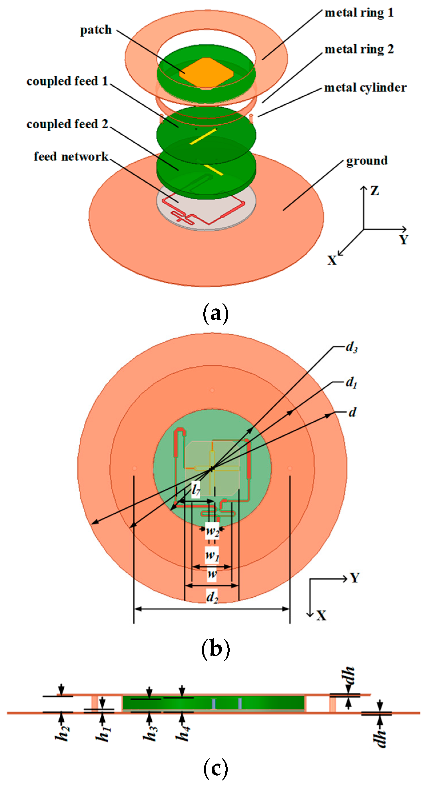
2. Antenna Design
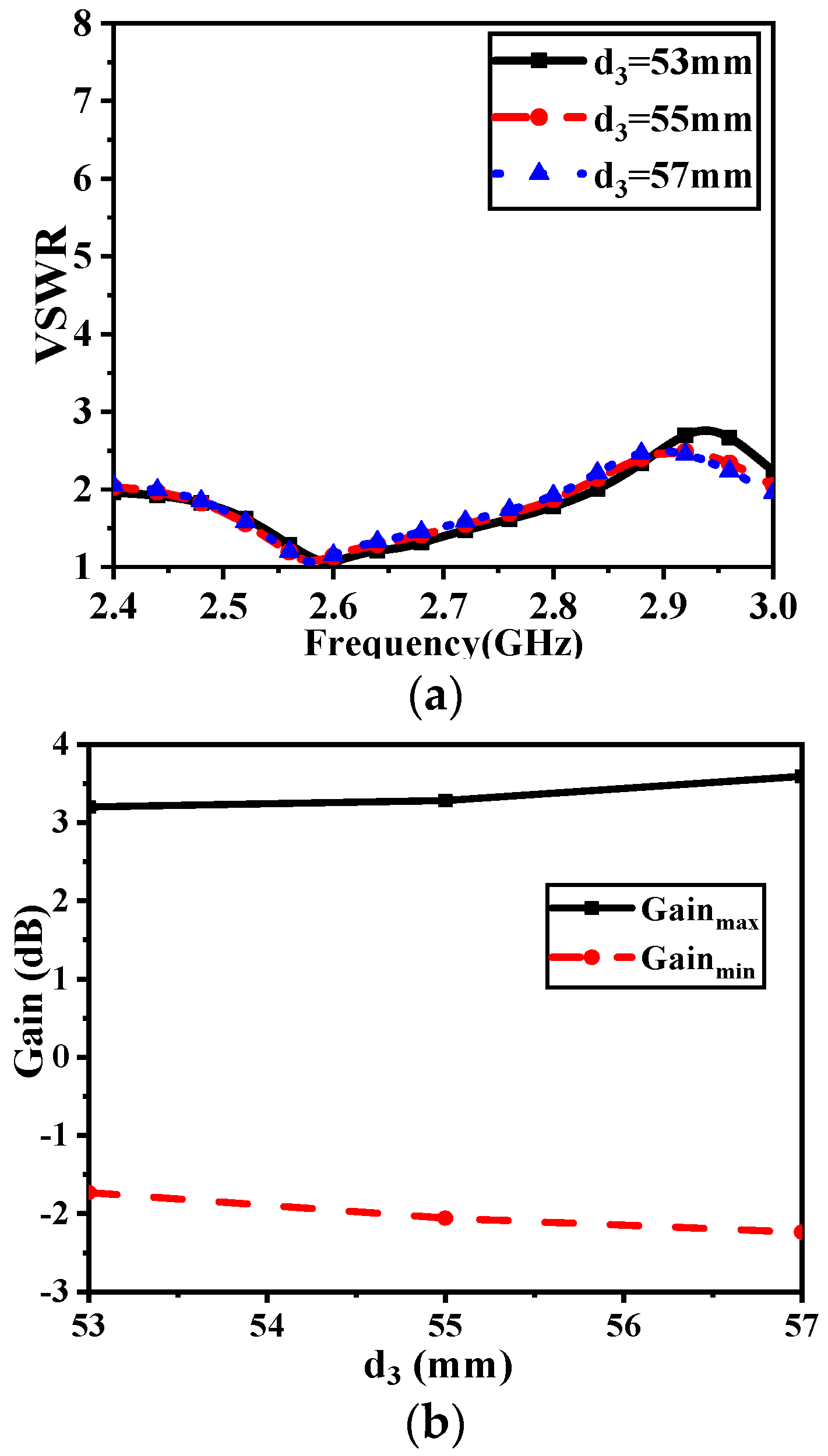
3. Parametric Study and Discussion
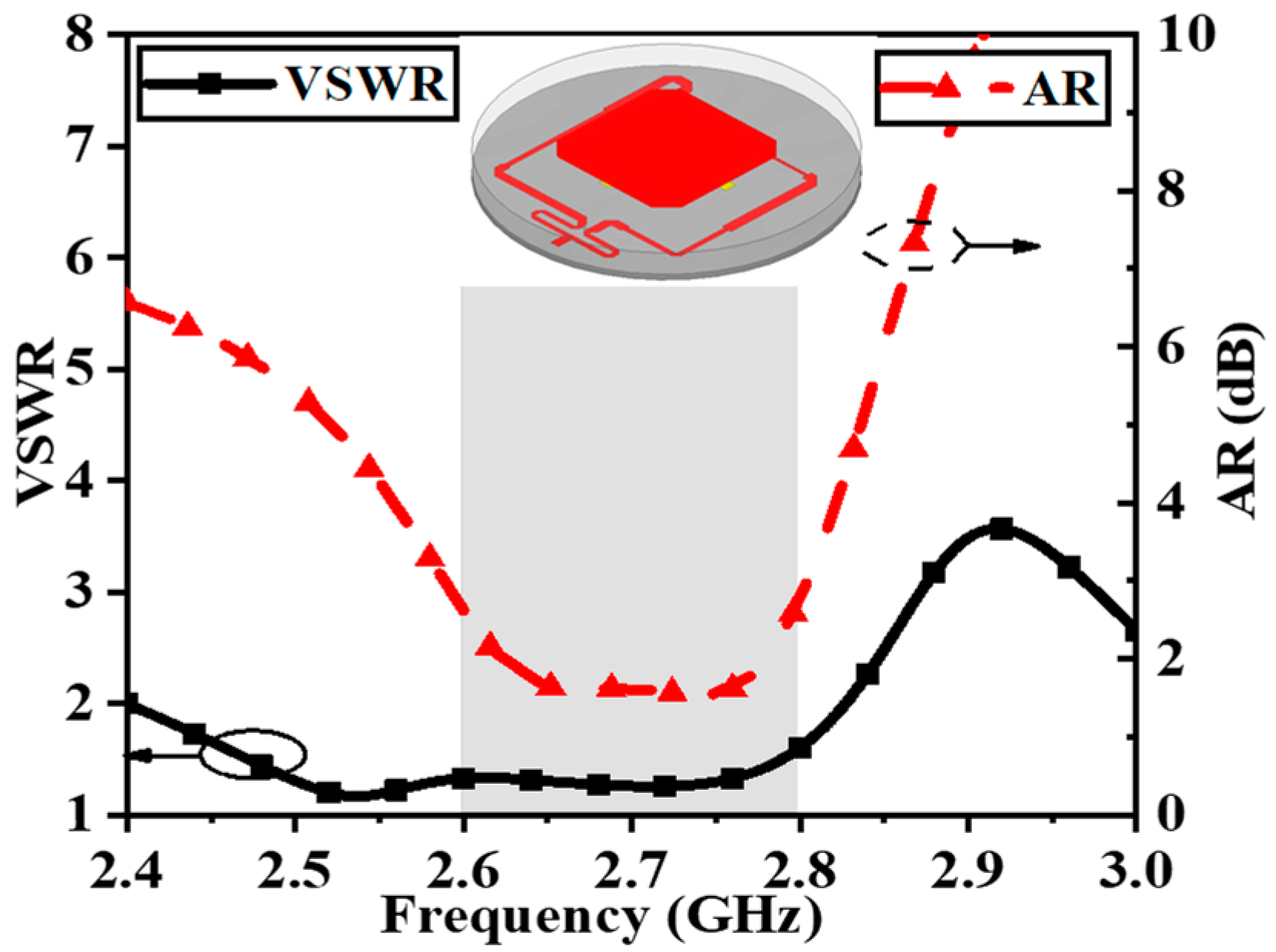
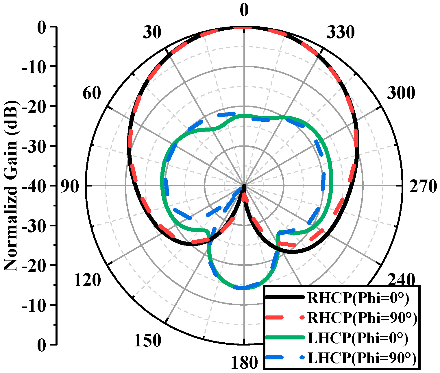
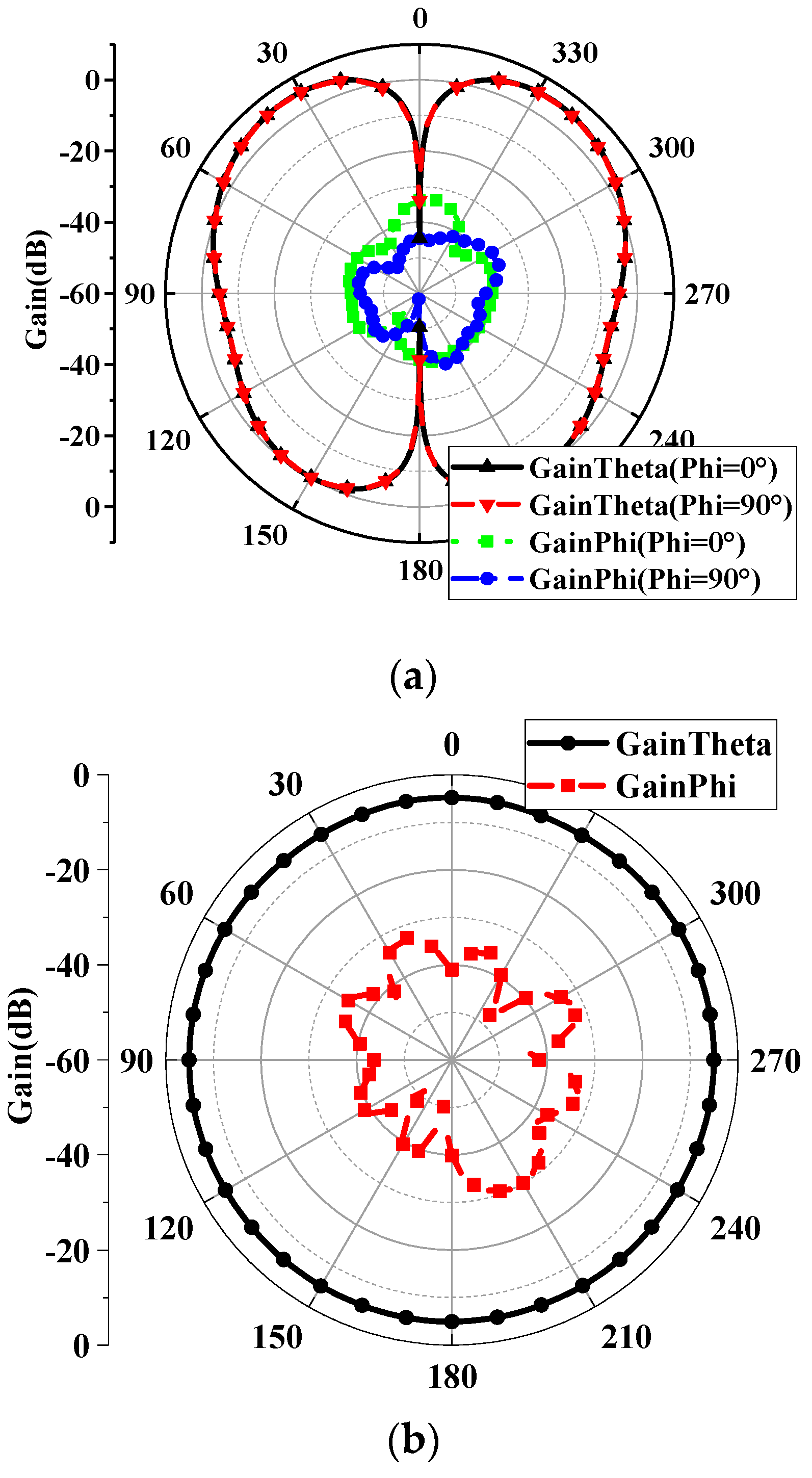
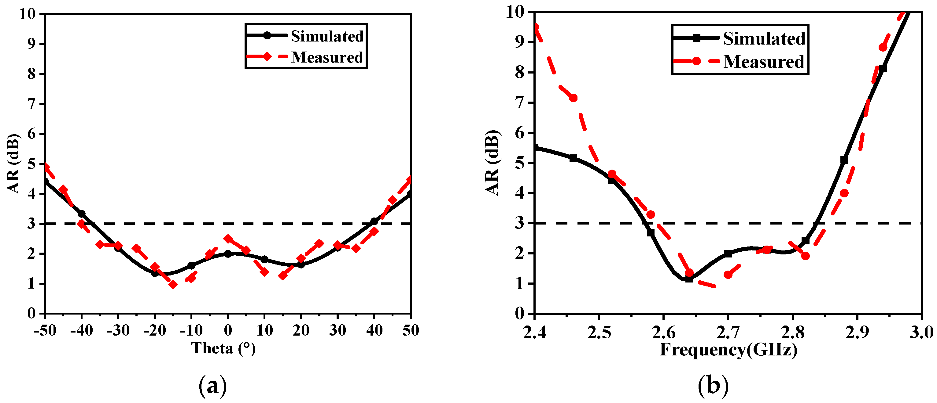
4. Simulated and Measured Results
5. Conclusions
Author Contributions
Funding
Data Availability Statement
Conflicts of Interest
References
- Yezhen, L.; Yongli, R.; Fan, Y.; Shenheng, X.; Jiannian, Z. A novel 28 GHz phased array antenna for 5G mobile communications. ZTE Commun. 2020, 18, 20–25. [Google Scholar] [CrossRef]
- Jou, C.F.; Wu, J.W.; Wang, C.J. Novel Broadband Monopole Antennas with Dual-Band Circular Polarization. IEEE Trans. Antennas Propag. 2009, 57, 1027–1034. [Google Scholar] [CrossRef]
- Shen, J.; Zhao, T.; Liu, X. Polarization reconfigurable patch antenna for wireless power transfer related applications. ZTE Commun. 2022, 20, 37–42. [Google Scholar] [CrossRef]
- Pan, Y.M.; Zheng, S.Y.; Hu, B.J. Wideband and Low-Profile Omnidirectional Circularly Polarized Patch Antenna. IEEE Trans. Antennas Propag. 2014, 62, 4347–4351. [Google Scholar] [CrossRef]
- Yang, X.; Yin, Y.Z.; Hu, W.; Zuo, S.L. Low-Profile, Small Circularly Polarized Inverted-L Antenna With Double-Folded Arms. IEEE Antennas Wirel. Propag. Lett. 2010, 9, 767–770. [Google Scholar] [CrossRef]
- Wang, Y.; Huang, Q.; Yu, Z.; Shi, X. A Broad-band Dual Circularly Polarized Microstrip Antenna with Low-profile. In Proceedings of the 2021 IEEE MTT-S International Wireless Symposium (IWS), Nanjing, China, 23–26 May 2021; pp. 1–3. [Google Scholar] [CrossRef]
- Zhou, S.G.; Li, J.Y. Low-Profile and Wideband Antenna. IEEE Antennas Wirel. Propag. Lett. 2011, 10, 373–376. [Google Scholar] [CrossRef]
- Wen, S.; Dong, Y. A Low-Profile Vertically Polarized Antenna With Conical Radiation Pattern for Indoor Micro Base Station Application. IEEE Antennas Wirel. Propag. Lett 2021, 20, 169–173. [Google Scholar] [CrossRef]
- Li, Q.; Lu, W.J.; Wang, S.G.; Zhu, L. Planar Quasi-Isotropic Magnetic Dipole Antenna Using Fractional-Order Circular Sector Cavity Resonant Mode. IEEE Access 2017, 5, 8515–8525. [Google Scholar] [CrossRef]
- Pan, G.; Li, Y.; Zhang, Z.; Feng, Z. Isotropic Radiation from a Compact Planar Antenna Using Two Crossed Dipoles. IEEE Antennas Wirel. Propag. Lett. 2012, 11, 1338–1341. [Google Scholar]
- Cai, Y.M.; Gao, S.; Yin, Y.; Li, W.; Luo, Q. Compact-Size Low-Profile Wideband Circularly Polarized Omnidirectional Patch Antenna with Reconfigurable Polarizations. IEEE Trans. Antennas Propag. 2016, 64, 2016–2021. [Google Scholar] [CrossRef]
- Zhou, S.G.; Tan, P.K.; Chio, T.H. Low-Profile, Wideband Dual-Polarized Antenna With High Isolation and Low Cross Polarization. IEEE Antennas Wirel. Propag. Lett. 2012, 11, 1032–1035. [Google Scholar] [CrossRef]
- Zhai, H.; Zhang, K.; Yang, S.; Feng, D. A Low-Profile Dual-Band Dual-Polarized Antenna With an AMC Surface for WLAN Applications. IEEE Antennas Wirel. Propag. Lett. 2017, 16, 2692–2695. [Google Scholar] [CrossRef]
- Ge, L.; Luk, K.M. A Low-Profile Magneto-Electric Dipole Antenna. IEEE Trans. Antennas Propag. 2012, 60, 1684–1689. [Google Scholar] [CrossRef]


| Parameter | d | d1 | d2 | d3 | w | w1 |
| Value (mm) | 125 | 95 | 72 | 55 | 24.8 | 18.8 |
| Parameter | w2 | dh | h1 | h2 | h3 | h4 |
| Value (mm) | 2 | 0.5 | 1 | 5 | 4.2 | 4.4 |
| Profile | Platform Effect | Δ | |
|---|---|---|---|
| [4] | 0.024λ | Great | 40 dB |
| [5] | 0.14λ | Little | 18 dB |
| [6] | 0.17λ | Little | 13 dB |
| [7] | 0.1λ | Little | 20 dB |
| [12] | 0.15λ | Little | 40 dB |
| [13] | 0.088λ | Little | 30 dB |
| [14] | 0.173λ | Little | 15 dB |
| [9] | 0.05λ | Great | 5.7 dB |
| [10] | 0.02λ | Great | 5 dB |
| This letter | 0.05λ | Little | 6 dB |
Disclaimer/Publisher’s Note: The statements, opinions and data contained in all publications are solely those of the individual author(s) and contributor(s) and not of MDPI and/or the editor(s). MDPI and/or the editor(s) disclaim responsibility for any injury to people or property resulting from any ideas, methods, instructions or products referred to in the content. |
© 2024 by the authors. Licensee MDPI, Basel, Switzerland. This article is an open access article distributed under the terms and conditions of the Creative Commons Attribution (CC BY) license (https://creativecommons.org/licenses/by/4.0/).
Share and Cite
Guo, J.; Zhang, H.; Liao, W.; Huang, Y.; Qu, L. A Low-Profile Wide-Angle Coverage Antenna. Electronics 2024, 13, 2749. https://doi.org/10.3390/electronics13142749
Guo J, Zhang H, Liao W, Huang Y, Qu L. A Low-Profile Wide-Angle Coverage Antenna. Electronics. 2024; 13(14):2749. https://doi.org/10.3390/electronics13142749
Chicago/Turabian StyleGuo, Jingli, Huanhuan Zhang, Wenhao Liao, Youhuo Huang, and Lanying Qu. 2024. "A Low-Profile Wide-Angle Coverage Antenna" Electronics 13, no. 14: 2749. https://doi.org/10.3390/electronics13142749
APA StyleGuo, J., Zhang, H., Liao, W., Huang, Y., & Qu, L. (2024). A Low-Profile Wide-Angle Coverage Antenna. Electronics, 13(14), 2749. https://doi.org/10.3390/electronics13142749