1. Introduction
In recent years, with the continuous development of the civil aviation industry, the annual passenger transportation volume of civil aviation has been increasing [
1]. As shown in
Figure 1a, over the past decade, the growth rate of China’s civil aviation passenger transport volume reached 58.2%. From 2020 to 2022, due to being impacted by the global COVID-19 pandemic, the passenger transport volume of civil aviation experienced a period of contraction, but it then rapidly recovered in 2023. The continuous growth in passenger air travel demand has driven a continuous increase in the number of civil aircraft [
2]. As shown in
Figure 1b, over the past decade, the growth rate of China’s civil aircraft fleet has reached 76.4%. The air traffic information network is the fundamental network that ensures the efficient and safe flight of civil aircraft [
3]. The continuous growth in air traffic demand imposes higher requirements on the air traffic information network [
4]. Traditional air traffic information networks are based on proprietary hardware [
5], where network functions, like firewalls and load balancers, are tightly coupled, making it difficult to flexibly deploy network functions in response to changing demands [
6]. As the civil aviation industry continues to advance toward digitization and intelligence [
7], the closed architecture of traditional air traffic information networks is struggling to meet the high-speed growth in air traffic service (ATS) demand [
8].
On 9 July 2020, the Radiocommunication Sector of the International Telecommunication Union (ITU-R) approved the 5G communication technology of the Third Generation Partnership Project (3GPP), and it adopted it as the 5G communication standard for the International Mobile Telecommunications (IMT-2020) in 2020 [
9]. China’s civil aviation’s new generation of the aviation broadband communication technology roadmap also explicitly aims to comprehensively build a civil aviation 5G application ecosystem. This effort aims to establish the future new generation of aviation broadband communication technology based on 5G as a core technology that promotes the digital transformation of civil aviation and empowers “smart civil aviation” [
10]. Network function virtualization (NFV) technology is a key 5G technology that addresses the issue of traditional rigidity in the air traffic information network [
11]. It is also a clearly defined key supporting technology in China’s civil aviation’s new generation aviation broadband communication technology roadmap. NFV is a virtualization technology that implements various network functions on a standardized general physical platform [
12]. Through decoupling software network functions from hardware physical platforms, NFV enables the flexible deployment of network functions [
13], separates the development cycles of software and hardware [
14], and allows for the dynamic expansion of network functions [
15]. With NFV technology, network functions can be treated like regular software [
16], allowing them to be flexibly deployed to any location in the network based on air traffic business requirements without the need for installing new hardware [
17]. This will reduce the operational costs of air traffic and also help the system to greatly adapt to the frequent dynamic business information transmission processes that will likely be in place in the future, i.e., “smart civil aviation” [
18,
19].
In an NFV-based air traffic information network, ATS is implemented through service function chains (SFCs) [
20]. A SFC consists of a series of Virtual Network Functions (VNFs) and virtual links (VLs) connecting the VNFs [
21,
22], thus enabling the end-to-end provision of air traffic services in the physical network. The deployment path of SFC1 is indicated by the red dashed arrow in
Figure 2. NFV technology has disrupted the closed architecture of tightly coupled hardware and software in traditional air traffic information networks, thus enabling the flexible deployment of air traffic services. However, it has also expanded the attack surface of air traffic information networks [
23]. On the one hand, decoupling software network functions (i.e., VNFs) from proprietary hardware has increased vulnerabilities [
24], making it easier for attackers to laterally move in standardized generic physical networks and to target critical VNFs. On the other hand, when multiple VNFs are deployed on the same physical platform, if an attacker successfully compromises one VNF, they may breach the logical isolation between the VNFs and conduct side-channel attacks on other VNFs [
25]. In an NFV-based air traffic information network, an attack on any VNF within an SFC will render the entire SFC incapable of providing services, thereby compromising the safety of flight operations. For instance, if the navigation service is attacked, the flight path could deviate, leading to flight delays and potentially even causing collisions, thus posing significant risks to the safety of individuals and property [
26].
In a response to the network attack risks faced by VNFs, this paper presents a SFC protection method based on honeypots and backup techniques that is aimed at reducing the resource cost of protecting air traffic information networks in NFV environments while enhancing network security. The main contributions of this paper are as follows:
- (1)
We analyzed the protection efficiency of honeypot protection technology, dedicated backup protection technology, and shared backup protection technology, deriving three guiding principles regarding SFC protection.
- (2)
We propose a topology-aware primary SFC deployment algorithm (TAPD), reducing the latency and resource cost of SFCs.
- (3)
We propose a resource-aware honeypot VNF deployment and removal algorithm (RAHDR) to enhance the security of SFCs against side-channel attacks.
- (4)
We propose a backup VNF deployment algorithm for maximizing the protection efficiency algorithm (BDMPE), thus enhancing the survivability of SFCs while reducing backup resource costs.
- (5)
Through experiments, we determined the maximum backup limit for SFCs in PBHB, and we verified that PBHB exhibits good performance at different SFC arrival rates. Furthermore, in comparing its performance with the SFC protection methods proposed by other scholars, we found that PBHB can optimize network resource costs while ensuring SFC security and latency.
The remaining sections of this paper are arranged as follows.
Section 2 introduces related works.
Section 3 describes the protection process of SFCs in the air traffic information network.
Section 4 analyzes the protection efficiency of the SFC protection mechanism.
Section 5 presents the proposed SFC protection method.
Section 6 evaluates the performance of the proposed SFC protection method through simulation experiments.
Section 7 summarizes the work of this paper and provides an outlook on future work.
2. Related Works
NFV technology, as a critical foundational technology for next-generation networks, has wide applications in various fields. Consequently, its security issues have garnered significant attention in academic circles. Reference [
8] discusses how the application of Mobile Edge Computing (MEC), SDN, and NFV technologies in aviation systems is expected to break the current closed network architecture and proposes a framework for collecting, monitoring, and distributing airspace resources among heterogeneous flying objects. Reference [
23] classified the potential attacks that 5G networks based on NFV may face into three dimensions: intra-layer, inter-layer, and the inter-administrative domain. This classification, borrowing from the STRIDE threat model, categorizes the most common attacks as spoofing, tampering, repudiation, information disclosure, DoS, and escalation of privilege. It also points out that attackers could breach the logical isolation between VNFs to launch side-channel attacks. Reference [
27] analyzed the threats and vulnerabilities in SFCs from four aspects: the service level, management and orchestration level, control level, and forwarding level. It summarized existing potential defense solutions for these threats. Reference [
28] introduced the applications of NFV technology and Software-Defined Networking (SDN) technology in 5G networks, while discussing and analyzing the attack types targeting 5G networks. Reference [
29] conducted a comprehensive investigation of emerging technologies such as the Internet of Things (IoT), SDN, NFV, and blockchain (BC), and it presented security challenges associated with integrating NFV technology into an SDN–IoT ecosystem. Reference [
30] pointed out that the deep integration of SDN, NFV, Service-Based Architecture (SBA), 5G new radio technologies, and large-scale IoT technologies will bring new trust and security threats to 5G networks, of which the study then summarized the potential threat challenges and proposed mitigation techniques. Reference [
31] investigated the security of smart homes based on the blockchain (BC), SDN, and NFV, and it also described the current security issues and proposed a new architecture for smart home security. Overall, these studies reviewed the security issues faced by NFV technology in various application scenarios, but they did not provide specific methods to address these issues.
To ensure the stable, reliable, and secure provision of services in the NFV environment, some scholars have considered efforts during the deployment phase to enhance the ability of SFCs to respond to risks. Reference [
12] proposes a secure-aware SFC deployment method for load balancing and latency optimization. This method merges VNFs based on security constraints and functional exclusions, and it then acquires the deployment locations of VNFs through the remaining resources, security, and load ratio of physical nodes. Reference [
32] proposed a secure latency-optimized SFC deployment method based on the Viterbi algorithm. This method utilizes the path with the highest match of VNF security levels as the SFC deployment path, deploying VNFs on the corresponding server nodes. Reference [
33] employed machine learning methods to deploy secure VNFs based on NFV performance, thus aiming to mitigate distributed denial of service attacks on the industrial IoT. Reference [
34] introduced the concept of SFC trustworthiness, quantifying the authenticity, availability, and reliability of VNFs from temporal and spatial perspectives. Subsequently, it selected VNF nodes based on user trustworthiness, and it further designed a trust-based SFC deployment strategy. Reference [
35] incorporated the Secure Service Level Agreement (SSLA) into SFC deployments, initially proposing a Maximum-Security (MS) SFC deployment algorithm, which formed the basis for a subsequent algorithm named MCSG-FA. The goal was to meet SSLA requirements while minimizing deployment costs.
If the security optimization of SFCs is only considered during the deployment phase, i.e., once a VNF in a SFC is attacked and fails, the entire SFC will not be able to provide services normally. Therefore, many scholars have proposed protecting SFCs through backup mechanisms. Reference [
36] proposed a reliability-aware SFC backup protection method (RABP). RABP first integrates the primary VNFs as much as possible using a breadth-first search method. Next, it deploys them using methods that enhance reliability and optimize latency, and it then deploys backup VNFs using a resource-efficient backup selection method. Reference [
37] introduced a novel reliability-aware adaptive deployment scheme called RAD for deploying and backing up SFCs in edge and cloud environments. RAD combines static and dynamic backup technologies, striving to find the optimal balance between the required SFC availability and backup costs. Reference [
38] proposed a dynamic backup sharing method (DBS). It first models the shared backup problem between different VNFs in a type of integer linear programming, then deploys primary VNFs using a greedy algorithm, and finally deploys backup VNFs using a shared backup mechanism. Reference [
39] presented a static backup sharing protection technique for pair-node protection to address virtual node failures in NFV environments. This method attempts to maximize the backup sharing between selected virtual nodes, but it only considers situations where a single virtual node fails. Reference [
40] analyzed software and hardware fault models to ensure the reliability of SFCs, and it proposed a single service chain solution with homogeneous VNFs (SOV) for single-flow scenarios. That approach first deploys primary VNFs using the k-shortest path algorithm, and it then deploys backup VNFs using a dedicated backup mechanism. Reference [
41] proposed an online backup deployment scheme called DPP to address the online VNF backup problem under availability constraints. DPP needs to solve an integer programming problem at the beginning of each time slot, and it utilizes the proposed dynamic programming-based algorithm to solve this problem. Reference [
42] only addressed the reliability requirements of different services by proposing a multi-mode VNF backup scheme, and it also introduced an online SFC reliability protection scheme to handle dynamic SFC requests in distributed cloud networks.
The current research on SFC protection mainly focuses on the physical node or the VNF failure issues caused by DoS attacks. It assumes that the failure of each VNF is independent of the others and fails to consider the scenario where an attacker, upon successfully taking control of one VNF, can breach the logical isolation between VNFs to launch side-channel attacks on other VNFs. To address this issue, this paper proposes an SFC protection method based on honeypots and backup techniques (PBHB). In PBHB, the TAPD algorithm is proposed as the deployment method for the primary SFC. The TAPD algorithm establishes topological constraints that are aimed at deploying the primary SFC along the shortest path between the source and destination endpoints, thus reducing SFC latency and deployment resource costs. Subsequently, the RAHDR algorithm is proposed for deploying honeypot VNFs in the physical network, thereby providing initial protection for the SFCs. The RAHDR algorithm installs honeypot VNFs in resource nodes via hosting multiple VNFs, thus decreasing the risk of side-channel attacks against the VNFs. Finally, the BDMPE algorithm is proposed to offer backup for SFC instances that still do not meet security requirements, providing a secondary layer of protection. The BDMPE algorithm selects the most efficient protection scheme for backing up SFCs, thus enhancing SFC security while reducing protection resource costs. Compared to the existing research, our proposed PBHB method innovatively utilizes honeypot technology to reduce the side-channel attack risks faced by SFCs. Additionally, when combined with traditional backup solutions, it provides dual protection for SFCs, achieving greater protective effects with less of a resource cost.
3. Description of SFC Protection
As shown in
Figure 2, the air traffic information network is a complex air–space–ground-integrated network that integrates satellite platforms, aircraft, ground infrastructure, and ATS providers. The space network consists of satellite platforms, the air network includes various manned and unmanned aircraft, and the ground network comprises general servers, wireless access points, switches, and ATS providers (such as the meteorological center and surveillance center shown in
Figure 2). In the NFV environment, satellite platforms, UAV platforms, general servers, wireless access points, switches, etc., form the physical nodes in the physical network. Air traffic services are realized through SFCs, where satellite platforms, general servers, and UAV platforms form the resource nodes in the physical nodes, which are capable of supporting the operation of VNFs in the SFCs.
Figure 2 depicts the scenario in an NFV environment where ATS is provided to three users (Flight 4, Flight 3, and Flight 2) through three SFCs. In SFC1, the three VNFs are deployed on Servers 1, 4, and 8, respectively. In SFC2, the four VNFs are deployed on Servers 7 and 2 and Satellite Platforms 6 and 5. In SFC3, the three VNFs are deployed on Servers 1 and 2 and UAV 1. VNFs utilize the computing, storage, and network resources of the physical platforms they are deployed on, while Virtual Links (VLs) consume the bandwidth resources of the physical links along their deployment paths.
3.1. Problem Description
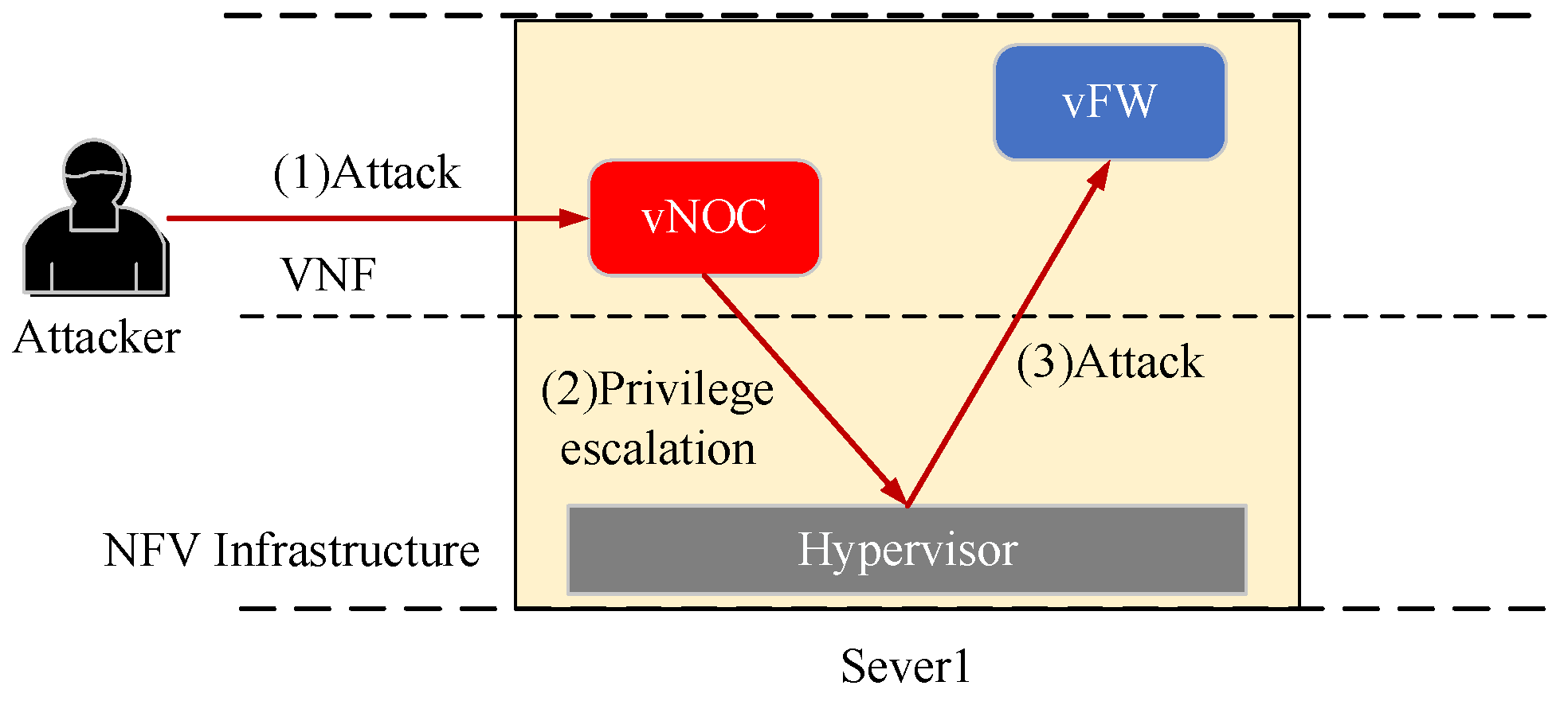
When multiple VNFs are deployed on the same physical platform, the NFV management and orchestration (NFV NANO) module logically isolates them through a hypervisor. Therefore, when a VNF is attacked and compromised, attackers may exploit vulnerabilities in the hypervisor to breach the logical isolation, thus gaining control over other VNFs on that physical platform; we refer to this type of attack as a side-channel attack [
23]. Taking the scenario depicted in
Figure 1 as an example, VNF1 in SFC1 and VNF1 in SFC3 represent a virtual network optimization control (vNOC) and virtual firewall (vFW), which were both deployed concurrently on Server 1. As shown in
Figure 3, assuming the attacker successfully compromises vNOC, they may potentially execute privilege escalation to breach the logical isolation between vNOC and vFW, thereby gaining control over vFW. For instance, they could tamper with the access control policies in vFW, preventing normal traffic from passing through, and they could also heavily consume the computational resources allocated to vFW, thus rendering the FW inoperable.
When deployed into the physical network without any protection measures, if any VNF is attacked and fails, the entire SFC will be unable to provide services as intended. To ensure service availability, the current mainstream method for SFC protection involves backing up VNFs. The backup mechanism allows services to be switched to backup VNFs when the primary VNF is attacked and fails, thus ensuring service availability. However, it does not effectively prevent attackers from launching side-channel attacks on other VNFs on the same physical platform; thus, the backup VNFs remain vulnerable to side-channel attacks. If the backup VNF is attacked again, the SFC is still at risk of becoming paralyzed. In response to this issue, this paper proposes adding protection mechanisms to VNFs from a different perspective.
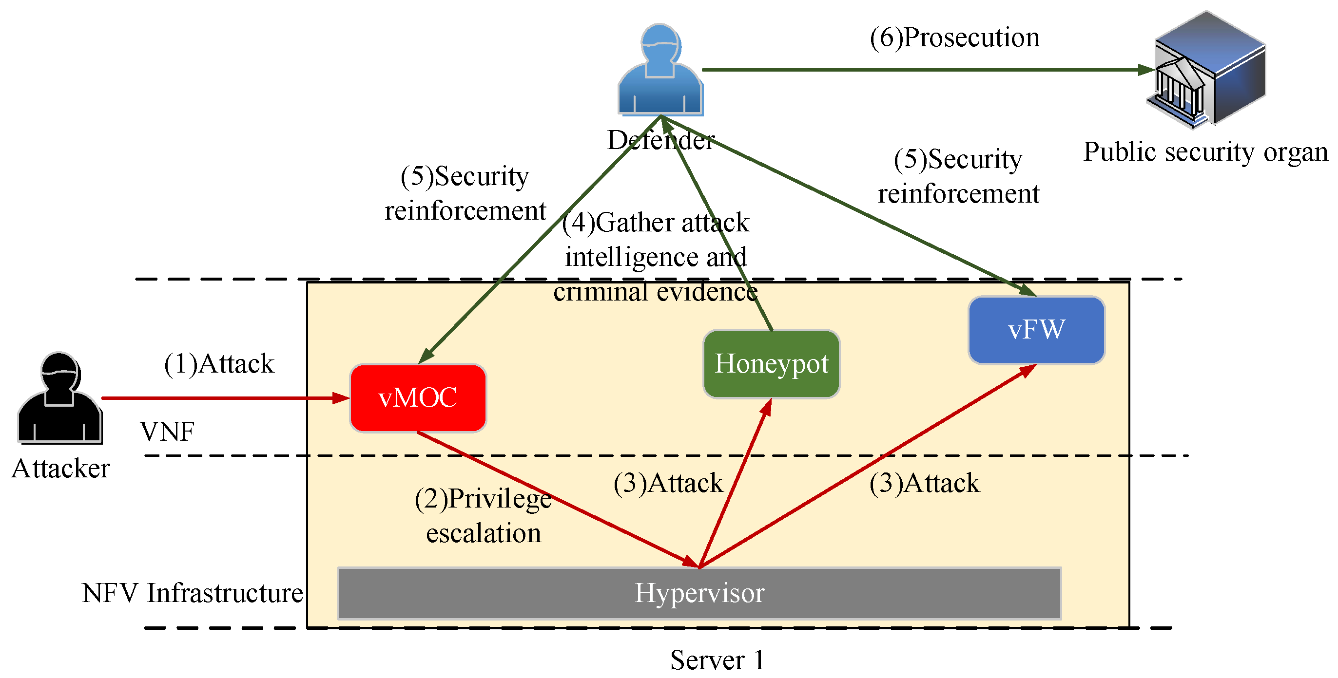
As illustrated in
Figure 4, we considered deploying a honeypot VNF in Server 1, which was meticulously designed by the network administrator (defender) as a decoy target for malicious attackers. Furthermore, despite the presence of many network security vulnerabilities, it can be fully controlled by the defender. When attackers infiltrate Server 1 from vNOC and breach the logical isolation between VNFs by breaking through the hypervisor, the honeypot VNF will lure attackers to conduct attacks on it. Once attackers penetrate the honeypot VNF, their attack actions will be captured and recorded by the defender. On the one hand, the defender can utilize this attack intelligence to analyze the tools and methods used by attackers, thereby implementing targeted network security reinforcement on normal VNFs. On the other hand, they can trace back and gather evidence on attackers, which may be used for prosecution when necessary.
3.2. Network Model
3.2.1. Physical Network
The physical network in the air traffic information network can be abstracted as a weighted undirected graph , where ( represents the i-th physical node) represents a set of physical nodes, including the server set Ns, the satellite platform set , the UAV set , the wireless access point or switch set , the flight set , and the ATS provider set . Servers, satellite platforms, and UAVs can host VNFs, whereas wireless access points or switches only provide access and switching functions; meanwhile, ATS providers and flights are the source and destination endpoints of the SFCs. For ease of subsequent expression, let the set of resource nodes in that can host VNFs be denoted as (where represents the i-th resource node that can deploy VNFs); thus, . The remaining available resources (computational, storage, and network) of the resource node are denoted as , with a processing delay for VNFs represented as . (where represents the physical link between physical node and ) denotes a set of physical links, including the set of wired links and wireless links . The remaining available bandwidth of the physical link is denoted as , with a transmission delay denoted as . Since this paper only investigates protection methods for SFCs where VNFs are under attack, it is assumed that all physical nodes and physical links are functionally reliable (meaning that all physical nodes and links do not experience functional failures).
3.2.2. SFCs
The SFCs set is , and SFC is represented by a septuple , where , , , , , represent the source endpoint, destination endpoint, primary VNF set, primary VL set, survival time, and lower limit of security, respectively. In addition, represents the -th primary VNF in . The resource requirements (computational, storage, and networking) of are denoted by , with vulnerability as . Moreover, is defined as the probability of a successful intrusion into when attackers directly target it, albeit it is dependent on the software version, existing vulnerabilities, and severity of . Next, represents the -th primary VL; when , then is between and ; when , then is between and ; when , then is between and . Additionally, denotes the bandwidth requirement of .
represents the backup VNFs set of
and
represents the
-th backup VNF in
. The primary VNF set protected by
is
. When
, then
is the dedicated backup of element of
, where the resource requirements and vulnerability of
are kept consistent with the primary VNF it protects. When
, then
is the shared backup of element of
, where the resource requirements of
is the maximum of the resource requirements of
. Moreover, the vulnerability of
is the minimum of the vulnerability of
, as shown in Equations (1) and (2).
where
represents the backup VLs set for
; the
in
represents the backup VLs set connecting
with the primary VNF;
represents the
-th backup VL in
, with its bandwidth requirement consistent with the primary VL it protects; and
represents the honeypot VNF installed in resource node
, with resource requirements denoted as
and the success rate of capturing attackers as
. The main symbols in this paper are explained in
Table 1.
3.3. Problem Formalization
We defined the following five binary variables:
where
represents whether the primary VNF
is deployed on resource node
, with
if true or
otherwise;
represents whether the backup VNF
is deployed on resource node
, with
if true and
otherwise;
represents whether the primary VL
is deployed on physical link
, with
if true and
otherwise;
represents whether the backup VL
is deployed on physical link
, with
if true and
otherwise; and
represents whether a honeypot VNF is deployed on resource node
in time slot
t, with
if true and
otherwise.
In the context of considering the risk of side-channel attacks, this paper formulated the SFC protection problem that aims to maximize the revenue-to-cost ratio as the following mixed-integer linear programming problem (MILP) with the optimization objective function shown in Equation (8).
In Equation (8),
represents the long-term average revenue-to-cost ratio, and its calculation method will be provided in
Section 3.4. The constraints of the MILP are shown in Equations (9) to (17).
Equations (9) and (10), respectively, indicate that each primary VNF and backup VNF can be deployed on a resource node, but each VNF cannot be split for deployment. Equation (11) indicates that each resource node can host one or more VNFs. Equation (12) denotes that each resource node must satisfy the resource requirements of the VNFs it hosts. Equations (13) and (14), respectively, indicate that each primary VL and backup VL can be deployed on a physical link. Equation (15) states that each physical link can support one or more VLs. Equation (16) specifies that each physical link must meet the bandwidth requirements of the VLs it carries. Equation (17) stipulates that each SFC must meet security requirements.
3.4. Evaluation Indicators
3.4.1. The Long-Term Average Revenue-to-Cost Ratio
In the
t-th timeslot, the set of surviving SFCs in the network is denoted as
, the set of resource nodes deploying honeypot VNFs is denoted as
, the revenue of the network at this moment is as in Equation (18), the resource cost of deploying SFCs is as in Equation (19), and the resource cost of deploying honeypot VNFs is as in Equation (20).
Here,
and
represent the weight coefficients of the resources occupied by VNF and VL, respectively, which are both set to 1 in this paper; and
and
represent the number of hops after deploying
and
onto the physical network, respectively. The long-term average revenue-to-cost ratio is defined as shown in Equation (21).
where
is an infinitesimal variable used to prevent the denominator in the expression from being 0.
3.4.2. The Long-Term Average Latency of the SFC
The long-term average latency of SFCs is defined by Equation (22).
where
represents the number of successfully deployed SFCs within time slot
.
3.4.3. The Long-Term Average Security of SFCs
The average security of SFCs surviving in time slot
t is calculated as in Equation (23).
Here,
represents the security of
, which is related to factors such as VNF vulnerability, deployment methods, protection methods, etc. The specific calculation method will be provided in
Section 4, and the long-term average security of the SFC is given by Equation (24).
3.4.4. The Long-Term Average Bandwidth Cost of SFCs
The average bandwidth cost of SFCs surviving in time slot
t is calculated as in Equation (25).
The long-term average bandwidth cost of the SFC is given by Equation (26).
3.4.5. The Long-Term Average Protection Resources Cost of SFCs
The average protection resource cost of SFCs surviving in time slot
t is calculated as in Equation (27).
The long-term average protection resources cost of SFCs is given by Equation (28).
3.4.6. The Long-Term Average Security-to-Protection-Resources Cost Ratio of SFCs
The long-term average security-to-protection-resources cost ratio of SFCs is given by Equation (29).
4. Analysis of SFC Protection
In this section, we analyze the protection efficiency of honeypot protection mechanisms, dedicated backup protection mechanisms, and shared backup protection mechanisms for SFCs in the context of considering the risk of side-channel attacks. Throughout this process, we assume that attackers have the capability to breach the logical isolation between VNFs.
4.1. Honeypot Protection Mechanism
As shown in
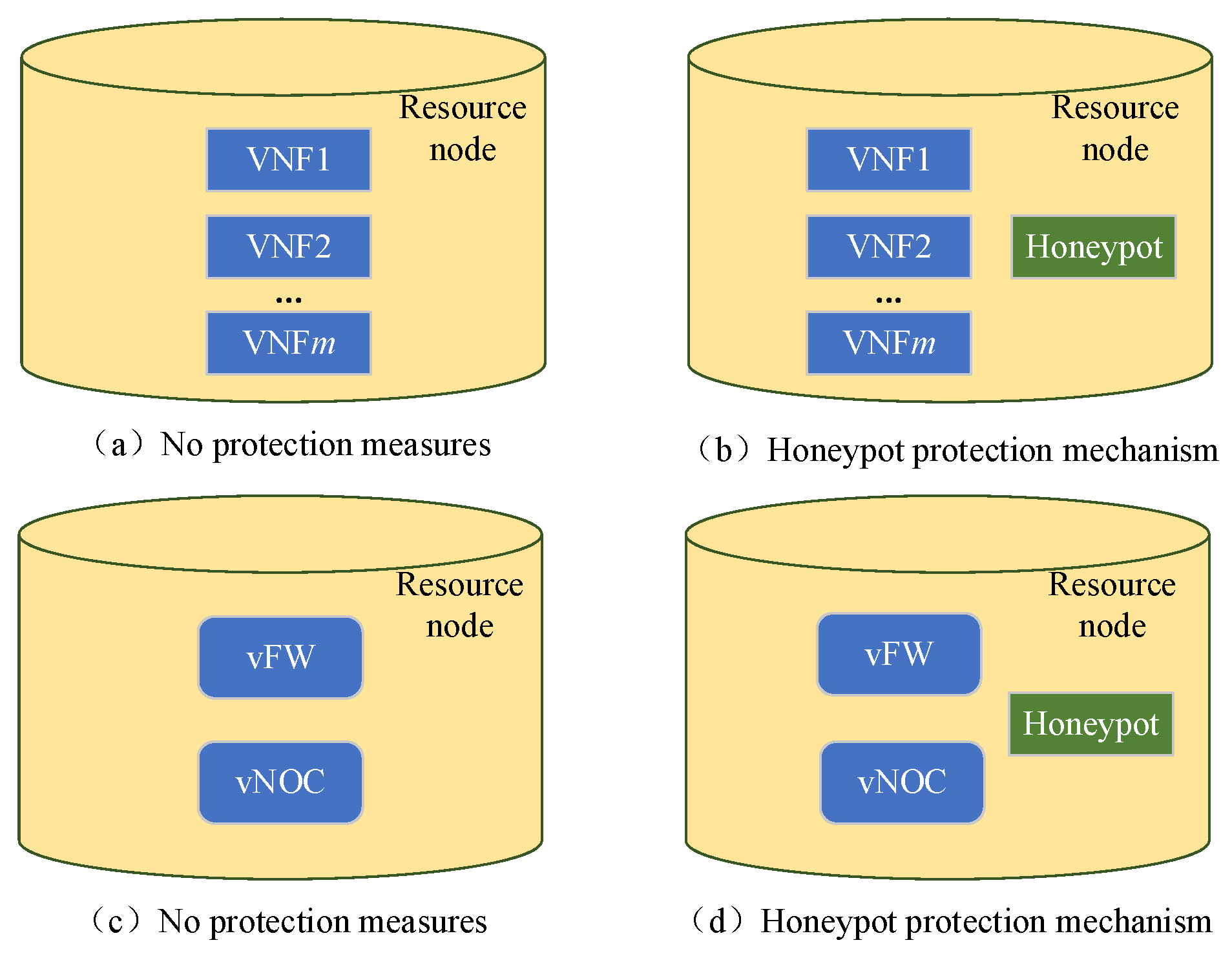
Figure 5, suppose m VNFs are deployed in a resource node, where each VNF has a vulnerability of
. As shown in
Figure 5a, if this resource node has no protection measures, then the attack risk faced by the
i-th VNF
is given by Equation (30), and the security of
is as shown in Equation (31).
In Equation (30), represents the direct attack risk faced by , which is equal to vul(v), with the physical meaning being the probability of a successful intrusion into when is the direct target of the attacker; and represents the side-channel attack risk faced by , which is equal to , with the physical meaning being the probability of an attacker successfully intruding into after infiltrating the internal of any other VNF besides and then breaching logical isolation. From Equation (30), it can be observed that, as increases, the side-channel attack risk faced by grows, and when m = 1, will not face side-channel attack risks.
As shown in
Figure 5b, a honeypot VNF
was deployed on the resource node with a resource requirement of
and a success rate of capturing attackers
. The attack risk faced by
vi is shown in Equation (32), and the security is defined by Equation (33).
Utilizing honeypot protection technology can enhance the security of each VNF deployed in the resource nodes, with the protection efficiency being represented by Equation (34).
It can be observed that σh increases with the increase of m, and when , .
Principle 1: When only one VNF is deployed in a resource node, the honeypot VNF does not provide protection to it. When multiple VNFs are deployed in a resource node, the honeypot VNF will protect all of them, and the more VNFs there are, the higher the level of protection efficiency.
We further illustrate the process of security degree calculation for VNFs via considering side-channel attack risks using the examples shown in
Figure 5c,d. Assuming two VNFs (vFW and vNOC) are deployed on the same resource node:
Figure 5c depicts the resource node without any protective measures, while
Figure 5d shows the resource node protected by honeypot measures. Let us assume the vulnerability of vFW and vNOC are both 0.05, thus indicating the probability of successfully intruding into their internals when attackers target them from the outside (i.e., without utilizing side channels) is 0.05. In the scenario depicted in
Figure 5c, the attack risk faced by vFW or vNOC is 0.05 + 0.05 × 0.05 = 0.0525, resulting in a security of 1 − 0.0525 = 0.9475. In the scenario shown in
Figure 5d, assuming the success rate of the honeypot VNF in trapping attackers is 0.8, the attack risk faced by vFW or vNOC is 0.05 + 0.05 × 0.2 × 0.05 = 0.0505, thus leading to a security of 1 − 0.0505 = 0.9495.
4.2. Dedicated Backup Mechanism
Assuming an SFC consists of
n VNFs, with each VNF having a resource requirement of
c(
v) and a vulnerability of
vul(
v), as well as each VL having a bandwidth requirement of
b(
l), then, for one of the VNFs, dedicated backup protection is implemented (assuming VNF2 is selected) with two possible protection schemes, as shown in
Figure 6. In Scheme 1, as shown in
Figure 6a, the backup VNF is deployed on the deployment path of the SFC, with a protection resource cost equal to
c(
v). In Scheme 2, which is shown in
Figure 6b, the backup VNF is not deployed on the deployment path of the SFC, and its protection resource overhead is equal to
. We first calculated the security
of VNF
based on Equations (31)–(34); if the resource node employs a honeypot protection mechanism, then
, otherwise
.
Assuming that the security of each VNF is denoted by
, then, when no backup protection is applied to the SFC, the security of the SFC is as shown in Equation (35).
In Scheme 1, as shown in
Figure 6a, the security of an SFC is given by Equation (36), and the protection efficiency is described by Equation (37).
In Scenario 2, as depicted in
Figure 6b, the security
of an SFC is equal to
, and the protection efficiency is given by Equation (38).
It is evident that .
Principle 2: Deploying backup VNFs on the deployment path of an SFC can enhance protection efficiency when providing dedicated backup protection for SFCs.
4.3. Shared Backup Mechanism
Assuming an SFC consists of
n VNFs, with each VNF having a resource requirement of
and vulnerability of
, as well as each VL having a bandwidth requirement of
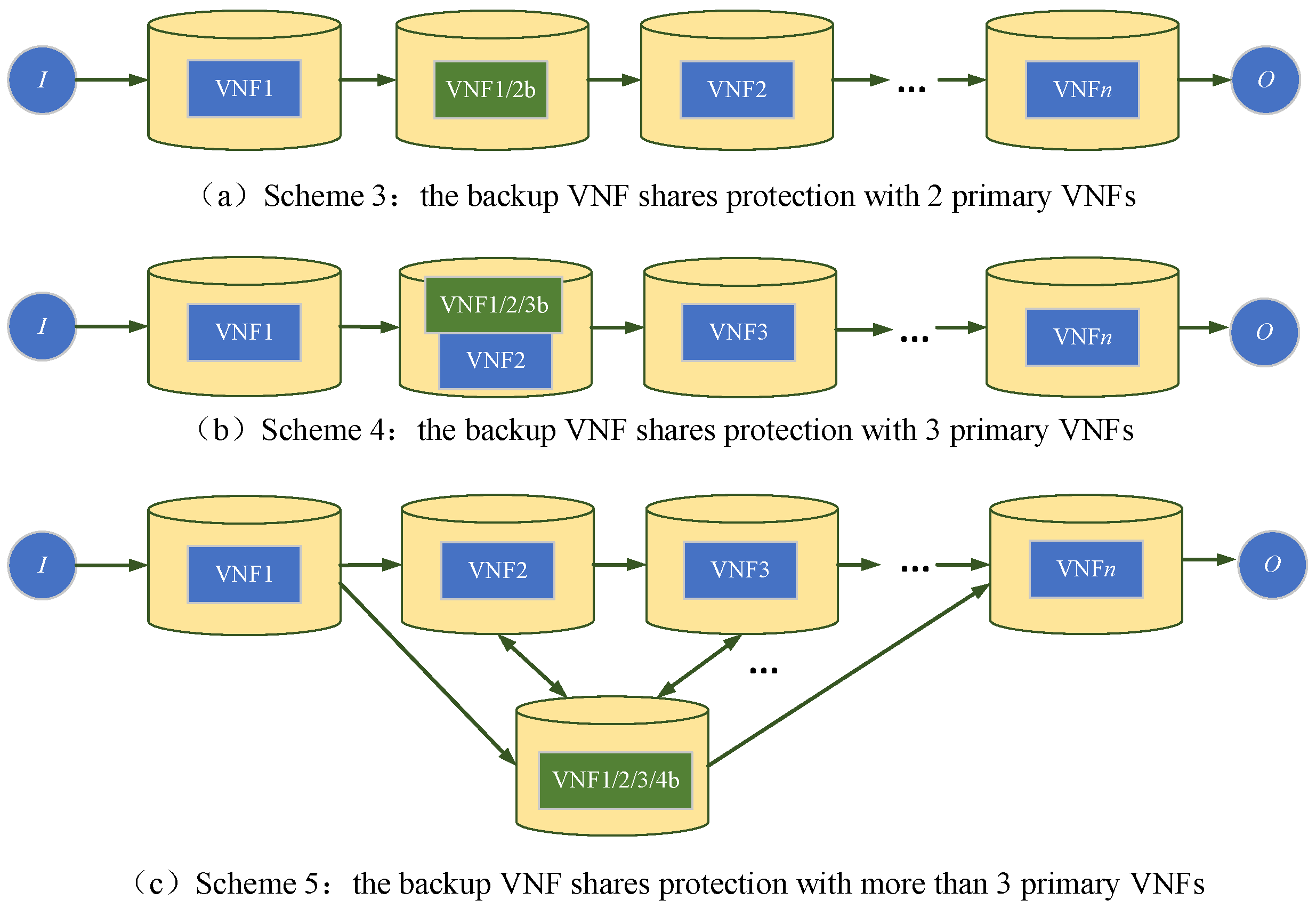
, then, by applying shared backup protection to certain VNFs, three potential protection schemes can be applied, as illustrated in
Figure 7. Via the analysis in
Section 4.2, it is evident that deploying backup VNFs on the deployment path of the SFC can enhance protection efficiency. Therefore, when the number of primary VNFs being protected is two or three, the shared backup VNFs in
Figure 7a,b is deployed on the SFC deployment path.
In Scheme 3, as shown in
Figure 7a, the backup VNF shares protection with two primary VNFs, where the protection resource cost is
, the security of the SFC is given by Equation (39), and the protection efficiency is defined by Equation (40).
In Scheme 4, as shown in
Figure 7b, the backup VNF shares protection with three primary VNFs, where the protection resource cost is
c(
v), the security of the SFC is given by Equation (41), and the protection efficiency is defined by Equation (42).
In Scheme 5, as shown in
Figure 7c, the backup VNF shares protection with
primary VNFs, where the protection resource cost is
, the security of the SFC is given by Equation (43), and the protection efficiency is defined by Equation (44).
where
is a monotonically increasing function with respect to
; therefore, in Scheme 5, the protection efficiency is maximized when all VNFs are subjected to shared backup protection. Through Equation (45), the maximum value of
can be calculated.
It is easy to determine that when comparing Schemes 1 to 5.
Principle 3: When implementing backup protection for SFCs, the most efficient approach is to apply shared backup protection to either three VNFs or to all VNFs, thus following the specific relationships indicated in Equation (46).
5. Design of the SFC Protection Method
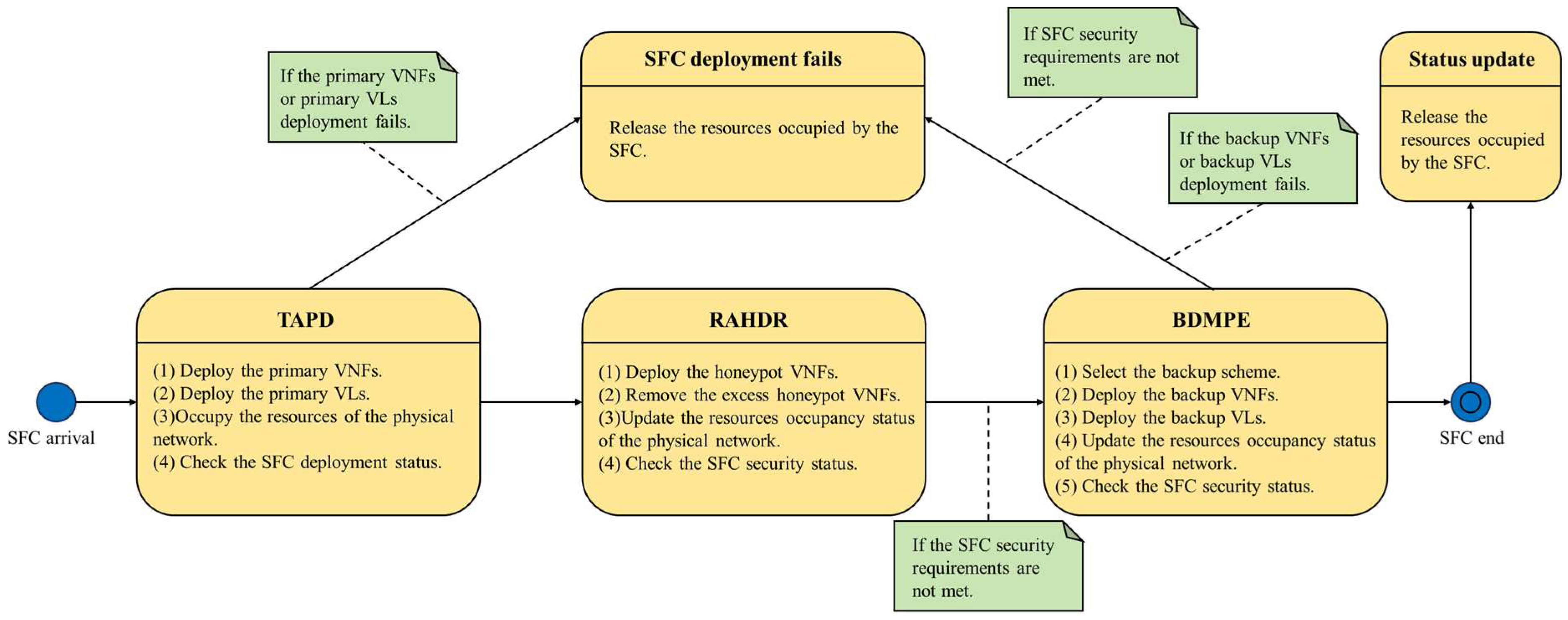
This section introduces a SFC protection method based on honeypots and backup techniques (PBHB) that is aimed at enhancing the security of SFCs against side-channel attacks in an air traffic information network with minimal resource expenditure. PBHB comprises the topology-aware primary SFC deployment algorithm (TAPD), resource-aware honeypot VNF deployment and removal algorithm (RAHDR), and the backup VNF deployment algorithm for maximizing protection efficiency (BDMPE). The overall design of PBHB is illustrated in
Figure 8.
Upon the arrival of an SFC, the primary VNF and primary VL are deployed using the TAPD algorithm. If any of these primary VNF or primary VL cannot be deployed to the physical network, then the SFC deployment fails, leading to the release of the resources that were occupied by the SFC. Otherwise, the RAHDR algorithm is utilized next to adjust the honeypot VNFs on the resource nodes. Specifically, this involves removing honeypot VNFs that no longer provide protective functions and redeploying new honeypot VNFs based on the deployment status of VNFs in the network. As deploying a new SFC into the physical network increases the risk of side-channel attacks on earlier deployed SFCs in the network, it is necessary to assess the security status of all SFCs in the physical network after the honeypot VNF adjustment. For the SFCs that did not meet security requirements, the BDMPE algorithm is employed to provide backup protection. Should the backup VNFs or backup VLs be incapable of deployment in the physical network, or if their deployment in the physical network does not meet the security requirements of the SFC, then the SFC deployment fails, resulting in the release of the resources occupied by the SFC. Otherwise, the SFC deployment is successful, and the physical resources occupied by it are released at the end of its lifetime.
5.1. TAPD
When deploying the primary VNF, it is preferable to keep the length of the SFC deployment path short in order to reduce the latency and bandwidth resource cost. Simultaneously, to mitigate the risk of side-channel attacks faced by each VNF, it is advisable not to deploy an excessive number of VNFs in each resource node. Therefore, the design of the TAPD algorithm is described as follows, with the specific process outlined in Algorithm 1.
| Algorithm 1 TAPD |
Input:
Physical network G, remaining available resources C(), and SFC set F;
Output:
Primary VNF deployment results VNF_Dep, Primary VL deployment results VL_Dep;
1. for i = 1:|F|
2. Φ1 = { |ng∈Nv,C() ≥ c(vi1)};
3. if is empty(Φ1)
4. return fi is deployed failed
5. else
6. Φ2 = { | ∈ Φ1, hop(Ii, ) = min(hop(Ii, ))};
7. Φ3 = { | ∈ Φ2, |Mg| = min(|Mg|)};
8. VNF_Dep(1) = Φ3(1);
9. clear Φ1, Φ2, Φ3;
10. for j = 2:|Vi|
11. Φ1 = { | ∈ Nv,C() ≥ c(vij)};
12. if is empty(Φ1)
13. return fi is deployed failed
14. else
15. Φ2 = set diff(Φ1, VNF_Dep);
16. if isempty(Φ2)
17. return fi is deployed failed
18. clear Φ1;
19. else
20. Φ3 = { | ∈ Φ2, hop(VNF_Dep (i − 1), ) + hop(,Oi) = min(hop(VNF_Dep (i − 1), ) + hop(,Oi))};
21. Φ4 = { | ∈ Φ3, |Mg| = min(|Mg|)};
22. VNF_Dep(j) = Φ4(1);
23. end if
24. end if
25. end for
26. end if
27. clear Φ1, Φ2, Φ3, Φ4;
28. for j = 0: |Vi|
29. G1 = {(N1,E1)|N1 = N,E1 = E(B(egh) ≥ b(lij))};
30. if j == 0
31. VL_Dep(j) = getshortpaths(G1, Ii, VNF_Dep(j + 1));
32. elseif j == |Vi|
33. VL_Dep(j) = getshortpaths(G1, VNF_Dep(j), Oi);
34. else
35. VL_Dep(j) = getshortpaths(G1, VNF_Dep(j), VNF_Dep(j + 1));
36. end if
37. if isempty(VL_Dep(j))
38. return fi is deployed failed
39. end if
40. end for
41. return VNF_Dep, VL_Dep
42. end for |
The first phase of TAPD is to deploy the first VNF in SFC (lines 1–9). First, select a set from the resource node set that meets the resource requirements of . If is an empty set, then the deployment of fails. Otherwise, select a set from that has the shortest number of hops to the source endpoint Ii, and then choose a set from that has the minimum number of deployed VNFs. Finally, select a node from to deploy vi1 and then clear , , and .
The second phase of TAPD is to deploy the subsequent VNF in (lines 10–27). First, select a set from the resource node set Nv that meets the resource requirements of . If is an empty set, then the deployment of fails. Otherwise, remove nodes already deployed by VNF in from to generate a new node set . If is an empty set, then the deployment of fails and is emptied. Otherwise, select a set from such that it minimizes the sum of distances from the deployment node VNF_Dep(i − 1) to and the destination endpoint . Then, filter from with the minimum number of VNFs deployed. Finally, select a node from to deploy , and clear , , , and .
The third phase of TAPD is to deploy the VL in (lines 28–40). First, eliminate links in the physical network that do not meet the bandwidth requirements of . Then, deploy on the shortest path between the source endpoint and VNF_Dep(1). Deploy on the shortest path between VNF_Dep(i) and VNF_Dep(i + 1). Deploy on the shortest path between VNF_Dep() and the destination endpoint . If any of these VLs cannot be deployed in the physical network, the deployment of fails.
5.2. RAHDR
On the one hand, when new SFCs are deployed in the physical network, then these new SFCs may not meet the security requirements; on the other hand, they will increase the side-channel attack risks faced by other SFCs in the network, thus potentially compromising their security beyond the required level. Therefore, this section designs the RAHDR algorithm to globally reinforce the security of surviving SFCs in the network with the aim of reducing the side-channel attack risks faced by each VNF. The RAHDR algorithm detects changes in the number of deployed VNFs in each time slot in resource nodes, deploys honeypot VNFs in resource nodes vulnerable to side-channel attacks, and removes the honeypot VNFs deployed in resource nodes without side-channel attack risks. The design description of the RAHDR is as follows, and the specific process is shown in Algorithm 2.
The first phase of RAHDR initializes (lines 1–3). Setting to the initial value of 0 indicates that, when , all of the resource nodes have not deployed honeypot VNF.
The second phase of RAHDR involves deploying and removing honeypot VNFs based on the changes in the number of VNFs deployed in the resource nodes (lines 4–17). For each resource node
, if the number of deployed VNFs in
at time slot
t is greater than or equal to two, and no honeypot VNF was deployed in
at time slot
t − 1, as well as the remaining available resources in
meeting the resource requirements of the honeypot VNF, then the honeypot VNF is deployed in
at time slot
t, while updating the remaining available resources in
(lines 6–8). If the number of deployed VNFs in
at time slot
t is less than two, and a honeypot VNF was deployed in
at time slot
t − 1, then the honeypot VNF in
is removed at time slot
t while updating the remaining available resources in
(lines 9–11). For all other cases, the deployment outcome of the honeypot VNF in
at time slot
t remains consistent with that of time slot
t − 1 (line 13).
| Algorithm 2 RAHDR |
Input: Physical network G, Primary VNF deployment results VNF_Dep;
Output: Honeypot VNF deployment results zg(t);
1. for g = 1:|Nv|
2. zg(0) = 0;
3. end for
4. for t = 1:end
5. for g = 1:|Nv|
6. if |Mg(t)| ≥ 2&& zg(t − 1) == 0&& C() ≥ c()
7. zg(t) = 1;
8. C() = C() − c()
9. elseif |Mg(t)| < 2&& zg(t − 1) == 1
10. zg(t) = 0;
11. C() = C() + c();
12. else
13. zg(t) = zg(t − 1);
14. end if
15. return zg(t)
16. end for
17. end for |
5.3. BDMPE
After using RAHDR to strengthen the security of the SFCs in the network, there may still be some SFCs that do not meet the security requirements. Therefore, this section designs the BDMPE algorithm to provide backup protection for these specific SFCs, thus aiming to further enhance their security and improve the success rate of SFC deployment. The BDMPE algorithm sets a maximum backup limit
kmax. When the number of backups does not exceed
kmax, it selects the backup scheme with the highest protection efficiency to protect the SFCs that do not meet the security requirements. The design description of the BDMPE is as follows, and the specific process is shown in Algorithm 3:
| Algorithm 3 BDMPE |
Input: Physical network G, Primary VNF deployment results VNF_Dep, and Primary VL deployment results VL_Dep;
Output: Protected primary VNF set , Backup VNF deployment results BVNF_Dep;
1. for i = 1:|Fser|
2. calculate S(fi);
3. if S(fi) <
4. k = 1;
5. while (S(fi) < && k < kmax)
6. if |Vi| == 1
7. = {vi1};
8. Φ1 = {| ∈Nv, ∈VL_Dep, C() ≥ c(vi1)};
9. if is empty(Φ1)
10. Φ2 = {| ∈Nv, hop(Ii, ) + hop(,Oi) == min(hop(Ii, ) + hop(,Oi)), C() ≥ c(vi1)};
11. if isempty(Φ2)
12. return fi is protected failed
13. else
14. BVNF_Dep(k) = Φ2(1);
15. k = k + 1;
16. end if
17. else
18. BVNF_Dep(k) = Φ1(1);
19. k = k + 1;
20. end if
21. elseif |Vi| == 2
22. = {vi1, vi2};
23. Φ1 = {| ∈Nv, ∈VL_Dep, C() ≥ max(c(vi1), c(vi2))};
24. if isempty(Φ1)
25. Φ2 = {| ∈Nv, hop(Ii, )+ hop(, VNF_Dep(j)) == min(hop(Ii, ) + hop(, VNF_Dep(j))), C() ≥ max(c(vi1), c(vi2))};
26. if isempty(Φ2)
27. return fi is protected failed
28. else
29. BVNF_Dep(k) = Φ2(1);
30. k = k + 1;
31. end if
32. else
33. BVNF_Dep(k) = Φ1(1);
34. k = k + 1;
35. end if
36. elseif |Vi| == 3
37. = {vi1, vi2, vi3};
38. if C(VNF_Dep(2)) < max(c(vi1), c(vi2), c(vi3))
39. Φ1 = {| ∈Nv, hop(Ii, )+ hop(, VNF_Dep(j)) == min(hop(Ii, )+ hop(, VNF_Dep(j))), C() ≥ max(c(vi1), c(vi2), c(vi3))};
40. if isempty(Φ1)
41. return fi is protected failed
42. else
43. BVNF_Dep(k) = Φ1(1);
44. k = k + 1;
45. end if
46. else
47. BVNF_Dep(k) = VNF_Dep(2);
48. k = k + 1;
49. end if
50. else
51 Φ1 = {| ∈Φ0, Φ0 = {VNF_Dep(j)| C(VNF_Dep(j) ≥ max(c(vi,j−1), c(vi,j), c(vi,j+1)), 1 < j < |Vi|}};
52. Φ2 = {| ∈Nv, hop(Ii, )+ hop(, VNF_Dep(j)) == min(hop(Ii, )+ hop(, VNF_Dep(j))), C() ≥ max(c(Vi))};
53. find ∈Φ2, make θ|Vi|() = min (θ|Vi|(Φ2));
54. find ∈Φ1, make μ() = min (μ(Φ1));
55. if θ|Vi|() < τ()
56. BVNF_Dep(k) = ;
57. = Vi;
58. k = k + 1;
60. else
61. BVNF_Dep(k) = ;
62. Φ3 = {vi,j−1, vi,j, vi,j+1|VNF_Dep(vi,j) == };
62. = Φ3;
63. end if
64. end if
65. end while
66. end if
67. end for |
The first phase of BDMPE is to determine whether the surviving SFCs in the current network need backup protection (lines 1–5). When SFC fi does not meet the security requirements and its backup count is less than kmax, then BDMPE will provide it with backup protection.
The second stage of BDMPE involves selecting the backup scheme with the highest protection efficiency based on the specific situation of fi to protect fi (lines 6–67).
When only one primary VNF is present in fi, priority is given to implementing protection Scheme 1 for it, i.e., applying dedicated backup protection to vi1 and deploying the backup VNF on the deployment path of fi. If Scheme 1 is not applicable, the next best Scheme 2 is chosen to protect fi, thus ensuring that the backup VNF is deployed in the physical network to minimize the bandwidth cost of the backup VL through the condition “hop(Ii, ) + hop(,Oi) == min(hop(Ii, ) + hop(,Oi)”. If neither of the two schemes is feasible, the protection of fi fails (lines 6–20).
When there are two primary VNFs in fi, the preference is to choose Scheme 3 for their protection, meaning that shared backup protection is implemented for vi1 and vi2, with the backup VNF deployed on the SFC deployment path between vi1 and vi2. If Scheme 3 cannot be used, the next best choice is Scheme 5 to protect fi while ensuring that, through the condition “hop(Ii, ) + hop(, VNF_Dep(j)) == min(hop(Ii, ) + hop(, VNF_Dep(j)))”, after deploying the backup VNF into the physical network, the bandwidth cost of the backup VL is minimized. If both schemes are unavailable, the protection of fi fails (lines 21–35).
When there are three primary VNFs in fi, priority is given to implementing protection using Scheme 4, which entails applying shared backup protection to vi1, vi2, and vi3, as well as deploying the backup VNF on the resource node where vi2 is deployed. If Scheme 3 is not feasible, the next best alternative, Scheme 5, is chosen to protect fi, while ensuring that, after deploying the backup VNF in the physical network, the bandwidth cost of the backup VL is minimized by the condition “hop(Ii, ) + hop(, VNF_Dep(j)) == min(hop(Ii, ) + hop(, VNF_Dep(j)))”. If neither of the two schemes is viable, the protection of fi fails (lines 36–50).
When the number of primary VNFs in fi is greater than three, the protection efficiency of Schemes 4 and 5 is compared according to Equation (46), and then the scheme with the highest protection efficiency is selected to implement protection for fi. In Scheme 4, a combination of three consecutively arranged VNFs in fi are first selected, thus ensuring that the resource node where the middle VNF is deployed has sufficient remaining resources to support the operation of the backup VNF. Then, the combination of VNFs with the smallest τ value from these combinations is selected as the VNF to be protectively shared for backup. Finally, the backup VNF is delivered to the resource node where the middle VNF is deployed. In Scheme 5, shared backup protection is implemented for all VNFs and the backup VNF is deployed on the resource node that minimizes the value of θn (lines 51–67).
6. Performance Evaluation and Analysis of SFC Protection Methods
This section describes three sets of simulation experiments to evaluate the performance of the PBHB method proposed in this paper. In the first set of experiments, the SFC arrival rate was set to
λ = 1/20 to assess the performance of the PBHB method under different maximum protection limits. In the second set of experiments, the maximum protection limit was set to
kmax = 2 to evaluate the performance of the PBHB method under different SFC arrival rates. In the third set of experiments, the SFC arrival rate was set to
λ = 1/20 and the maximum protection limit was set to
kmax = 2 to evaluate the performance difference between the PBHB and SFC protection methods proposed by other scholars in this field. The comparison methods included the dynamic backup sharing (DBS) method proposed in reference [
38] and the single service-chain solution with homogeneous VNFs (SOV) proposed in reference [
40]. To reduce the randomness of the experiments, each set of experiments was conducted 10 times, and their averages were taken as the final experimental results.
The simulation experiments were conducted using MATLAB 2018a software, with the host machine having an i7-10510U CPU, 16 GB RAM, and a Radeon RX640 graphics card. This paper generated a random connected network SubNetwork with 100 nodes to simulate an air traffic-distributed information network, where each node in SubNetwork connects with a probability of 0.05, resulting in 245 links, as illustrated in
Figure 9. In SubNetwork, 50 nodes are randomly selected as general servers, 10 nodes as satellite platforms, 20 nodes as UAV platforms, and 20 nodes as wireless access points or switches. The links connected to satellite platforms or UAV platforms are wireless links (WLL), while the others are wired links (WL). The simulation time was set to 50,000 units, where the arrival rate of an SFC follows a Poisson distribution with parameter
λ, and the lifetime follows a negative exponential distribution with the parameter
μ set to 1000. The experimental parameters were as shown in
Table 2.
6.1. Performance of PBHB at Different kmax Values
In the first group of experiments, we set the SFC arrival rate to
λ = 1/20 to evaluate the performance of the PBHB method under the maximum protection limits of
kmax = 1,
kmax = 2,
kmax = 3, and
kmax = 4. The experimental results, as shown in
Figure 10, indicate that the experimental outcomes for
kmax = 2,
kmax = 3, and
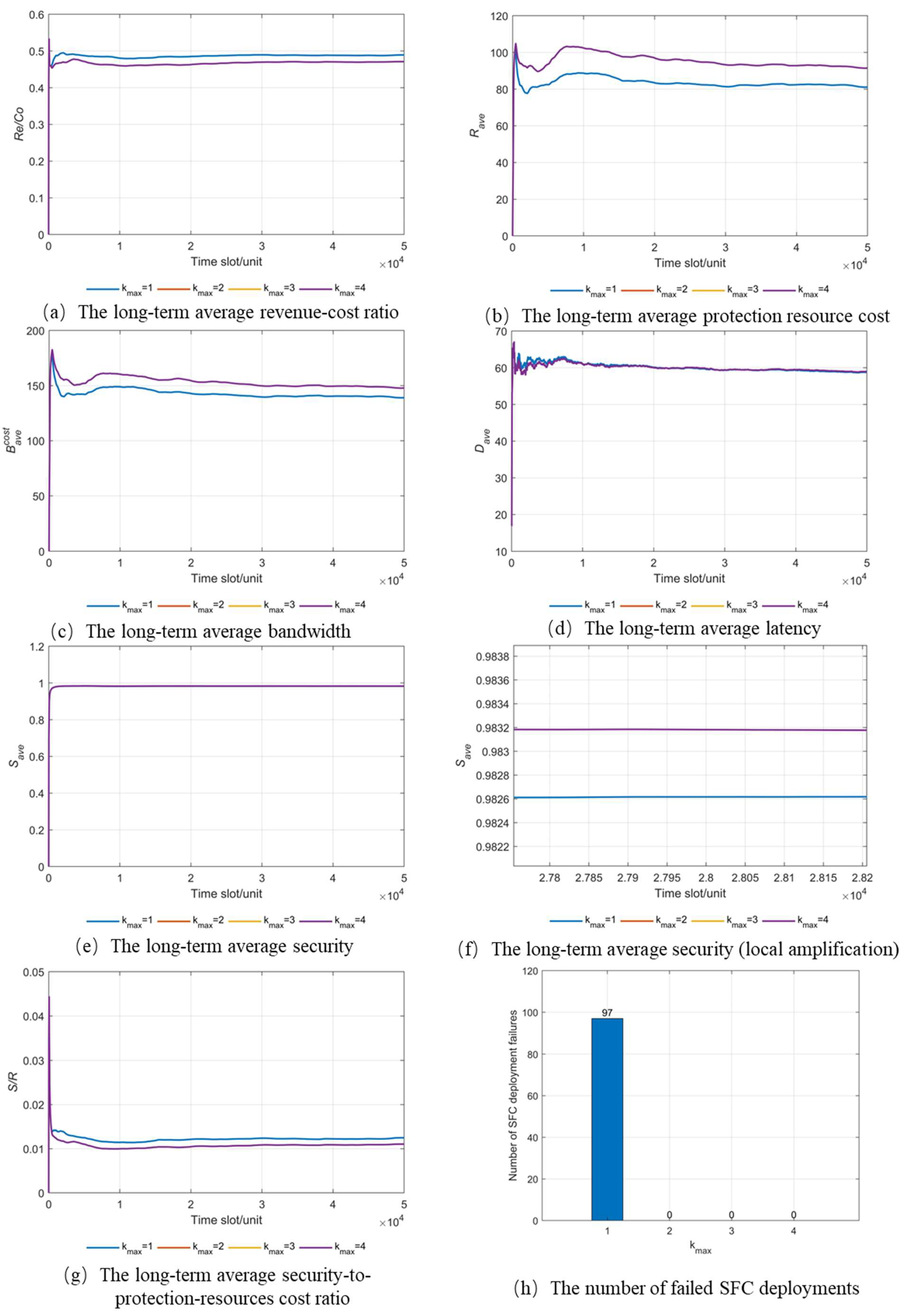
kmax = 4 overlap, thus suggesting that, in the PBHB method, backing up an SFC up to a maximum of two times is sufficient to meet security requirements. This is because PBHB leverages honeypot technology to reduce the side-channel attack risk of each VNF, thereby enhancing the security of each VNF.
Figure 10a shows the long-term average revenue–cost ratio results of the PBHB method at different
kmax values. It can be observed that when
kmax = 1, the network’s long-term average revenue–cost ratio is slightly higher than when other values of
kmax are used. This is because, at
kmax = 1, fewer backup protection resources are consumed, which is validated by
Figure 10b.
Figure 10b illustrates the long-term average protection resource cost of the PBHB method for different
kmax values. It shows that when
kmax = 1, fewer backup protection resources are consumed.
Figure 10c presents the long-term average bandwidth cost of the PBHB method for different
kmax values. It is evident that, when
kmax = 1, the SFC’s long-term average bandwidth cost is slightly lower than when other values of
kmax are used. This is because an increase in backup numbers leads to consuming more link bandwidth resources for deploying backup VLs.
Figure 10d depicts the long-term average latency of an SFC for different
kmax values using the PBHB method. It was observed that the long-term average latency of the SFC are consistent for different
kmax values. This is because the latency of SFCs is primarily determined by the deployment of the primary VNF and VL, and that changing
kmax values does not alter the deployment algorithm of the primary VNF and VL.
Figure 10e shows the long-term average security of an SFC using the PBHB method for different
kmax values.
Figure 10f provides a magnified view of
Figure 8e, demonstrating that, regardless of the
kmax value, the PBHB method maintains the SFC’s long-term average security above 0.9825. Furthermore, when
kmax = 1, the long-term average security of an SFC is slightly lower than when other values of
kmax are used.
Figure 10g shows the long-term average security-to-protection-resource cost ratio of SFCs under different
kmax values for PBHB. It can be observed that, for
kmax = 1, the long-term average security-to-protection resources cost ratios of an SFC are slightly higher than when
kmax takes other values.
Figure 10h illustrates the number of failed SFC deployments under different
kmax values for PBHB. It is observed that, when
kmax = 1, 97 SFC deployments failed due to not meeting security requirements, whereas for
kmax ≥ 2, all SFC deployments met the security requirements.
6.2. Performance of PBHB at Different λ Values
In the second group of experiments, we set the maximum protection limit to
kmax = 2 and evaluated the performance of the PBHB method at SFC arrival rates of
λ = 1/20,
λ = 1/25,
λ = 1/30, and
λ = 1/35. The experimental results are shown in
Figure 11.
Figure 11a depicts the long-term average revenue–cost ratio results of the PBHB method for various
λ values. It was observed that all outcomes stabilized around 0.5, thus showing a general trend where higher SFC arrival rates correspond to lower long-term average revenue–cost ratios in the network. This is because, with higher SFC arrival rates, more VNFs run concurrently in each resource node, leading to increased risks of side-channel attacks for each VNF. Consequently, more protection resources are required to ensure that SFCs meet security requirements.
Figure 11b illustrates the long-term average protection resource cost of the PBHB method for various
λ values. It was noticeable that all of the results eventually stabilized between 80 and 100, which demonstrated a trend where higher SFC arrival rates correspond to greater long-term average protection resource costs, thus validating the experimental results in
Figure 11a.
Figure 11c showcases the long-term average bandwidth cost of the PBHB method for different
λ values. It was evident that all of the outcomes eventually stabilized around 150, with the trends across the curves aligning with those in
Figure 11b.
Figure 11d displays the long-term average latency of an SFC under different
λ values using PBHB, which showed that all of the results stabilized around 60.
Figure 11e represents the long-term average security of an SFC for various
λ values using PBHB, thus demonstrating that all outcomes eventually stabilize at 0.98 or higher.
Figure 11f illustrates the long-term average security-to-protection-resources cost ratio of an SFC under different
λ values using PBHB, which revealed that all of the results ultimately stabilized around 0.01.
6.3. Performance Differences between PBHB and Other SFC Protection Methods
In the third group of experiments, we set the SFC arrival rate to
λ = 1/20 and the maximum protection limit to
kmax = 2 to evaluate the performance differences of the PBHB method compared to the DBS [
38] and SOV [
40] approaches that were proposed by other relevant studies. The experimental results are shown in
Figure 12,
Figure 13,
Figure 14,
Figure 15,
Figure 16,
Figure 17 and
Figure 18.
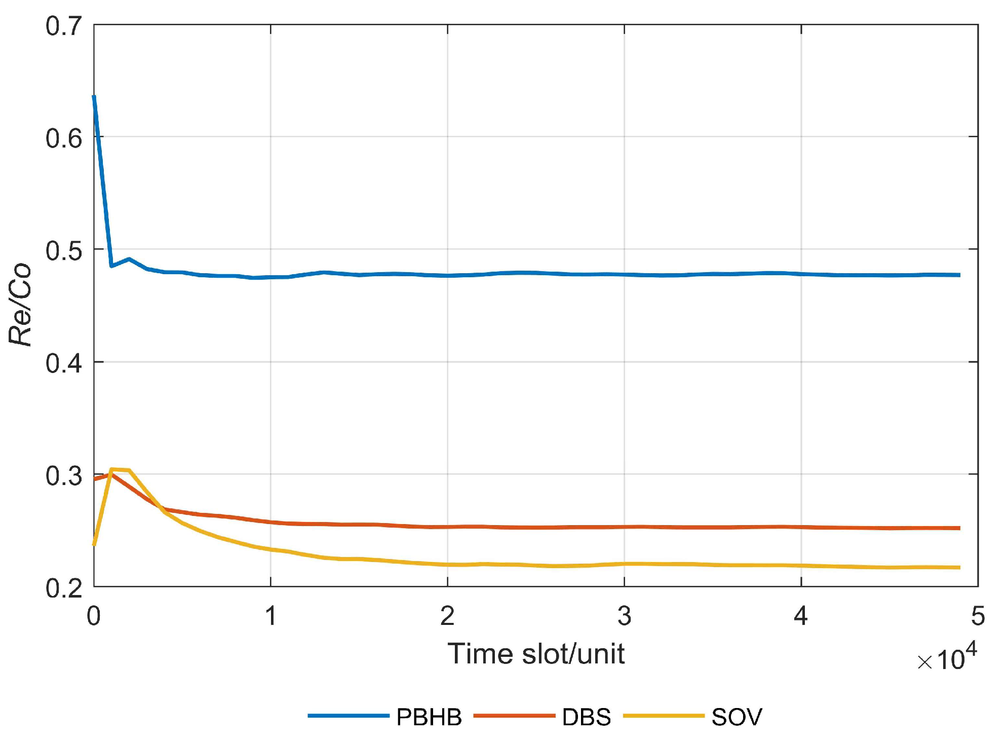
Figure 12 presents the long-term average revenue–cost ratio of the three different methods. It can be observed that PBHB has the highest long-term average revenue–cost ratio, reaching around 0.48; followed by the DBS method, which reached about 0.25; and the SOV approach ranked third, reaching approximately 0.22. This was because PBHB reduces the deployment path length of the primary SFC using the TAPD algorithm and deploys a backup VNF with the highest protection efficiency by employing the BDMPE algorithm, thus leading to the highest long-term average revenue–cost ratio. DBS reduces backup resource cost to some extent using a shared backup mechanism, resulting in the second highest long-term average revenue–cost ratio. Although the SOV method deploys the primary VNF on the shortest path between the source endpoint and the destination endpoint, the dedicated backup mechanism increases the backup resource cost, placing it third in terms of the long-term average revenue–cost ratio.
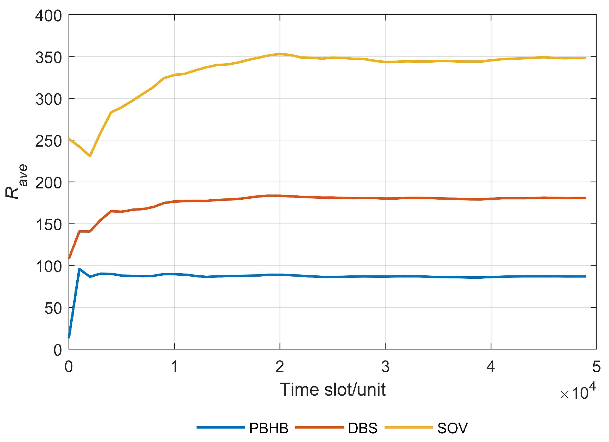
Figure 13 displays the long-term average protection resource costs of three different methods. It was evident that PBHB had the lowest long-term average protection resource cost for SFCs at around 80; followed by the DBS method at around 175; and the SOV method ranked third at around 350. This was because the PBHB method utilized the BDMPE algorithm to select the most efficient protection scheme for deploying backup VNFs, thus resulting in the lowest long-term average protection resource cost for an SFC. The DBS approach deploys backup VNFs using a shared backup mechanism, hence ranking second in long-term average protection resource costs for an SFC. SOV deploys backup VNFs using a dedicated backup mechanism, resulting in it being ranked third in long-term average protection resource costs for an SFC.
Figure 14 presents the long-term average bandwidth cost results of three different methods. It is evident that PBHB had the lowest long-term average bandwidth cost at around 140. SOV followed with approximately 265, while DBS ranked third with around 300. This was because PBHB opted for strategies that reduce link bandwidth costs when deploying both primary and backup VNFs, thus resulting in the lowest long-term average bandwidth cost for an SFC. SOV minimized link bandwidth costs to the fullest extent during primary VNF deployment, hence ranking second in long-term average bandwidth costs for an SFC. DBS did not prioritize reducing the link bandwidth costs during primary VNF deployment, resulting in it ranking third in long-term average bandwidth costs for an SFC.
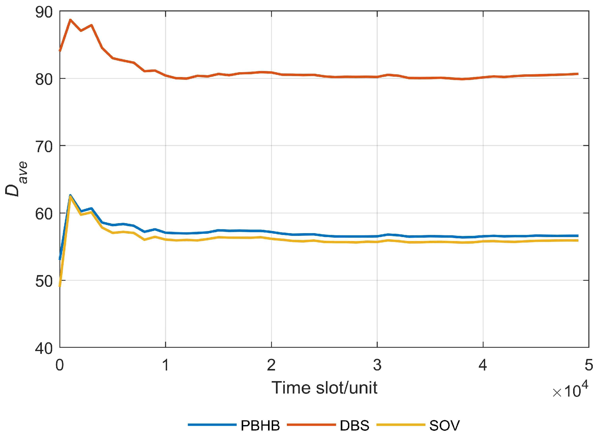
Figure 15 presents the long-term average latency of three different methods for an SFC. It can be observed that the SFC long-term average latency of SOV was the lowest at around 56. PBHB followed with around 57, while DBS ranked third with around 80. This was because SOV deploys the primary VNF on the shortest path between the source and destination endpoints, resulting in the lowest long-term average latency for an SFC. Although PBHB reduces the deployment path length of the primary SFC using the TAPD algorithm, the constraints set have some flexibility, leading to less strict deployments of the primary VNF on the shortest path between the source and destination endpoints, thus resulting in the second position in the ranking for the long-term average latency of an SFC. SOV does not consider deployment path length when deploying the primary SFC, resulting in it being ranked third in the long-term average latency of an SFC.
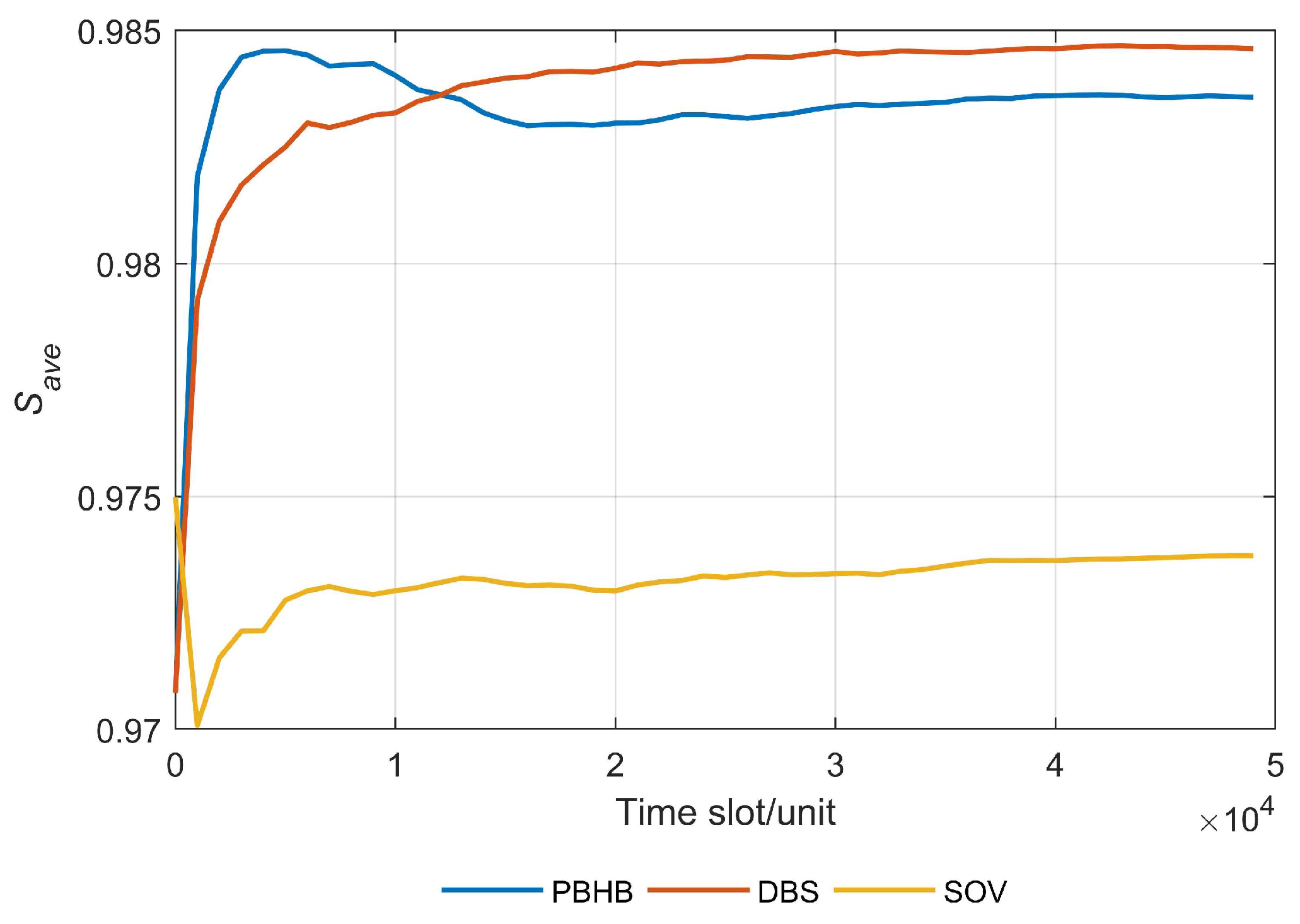
Figure 16 displays the long-term average security of three different methods. It is evident that DBS had the highest long-term average security for an SFC at around 0.984. Following this, PBHB ranked second with an average of approximately 0.983. SOV ranked third with an average of about 0.973. This was because DBS employs a shared backup mechanism to protect all VNFs in real time, hence achieving the highest long-term average security for an SFC. On the one hand, PBHB safeguards various VNFs in different resource nodes by deploying honeypot VNFs. On the other hand, it utilizes the BDMPE algorithm to select the most efficient protection scheme to safeguard certain VNFs within an SFC rather than ensuring real-time protection for all VNFs, thus resulting in the second rank for long-term average security. SOV employs a dedicated backup mechanism to protect VNFs; yet, it lacks adequate resources to provide sufficient protection for each VNF individually, thus leading to its third position in the long-term average security for an SFC.
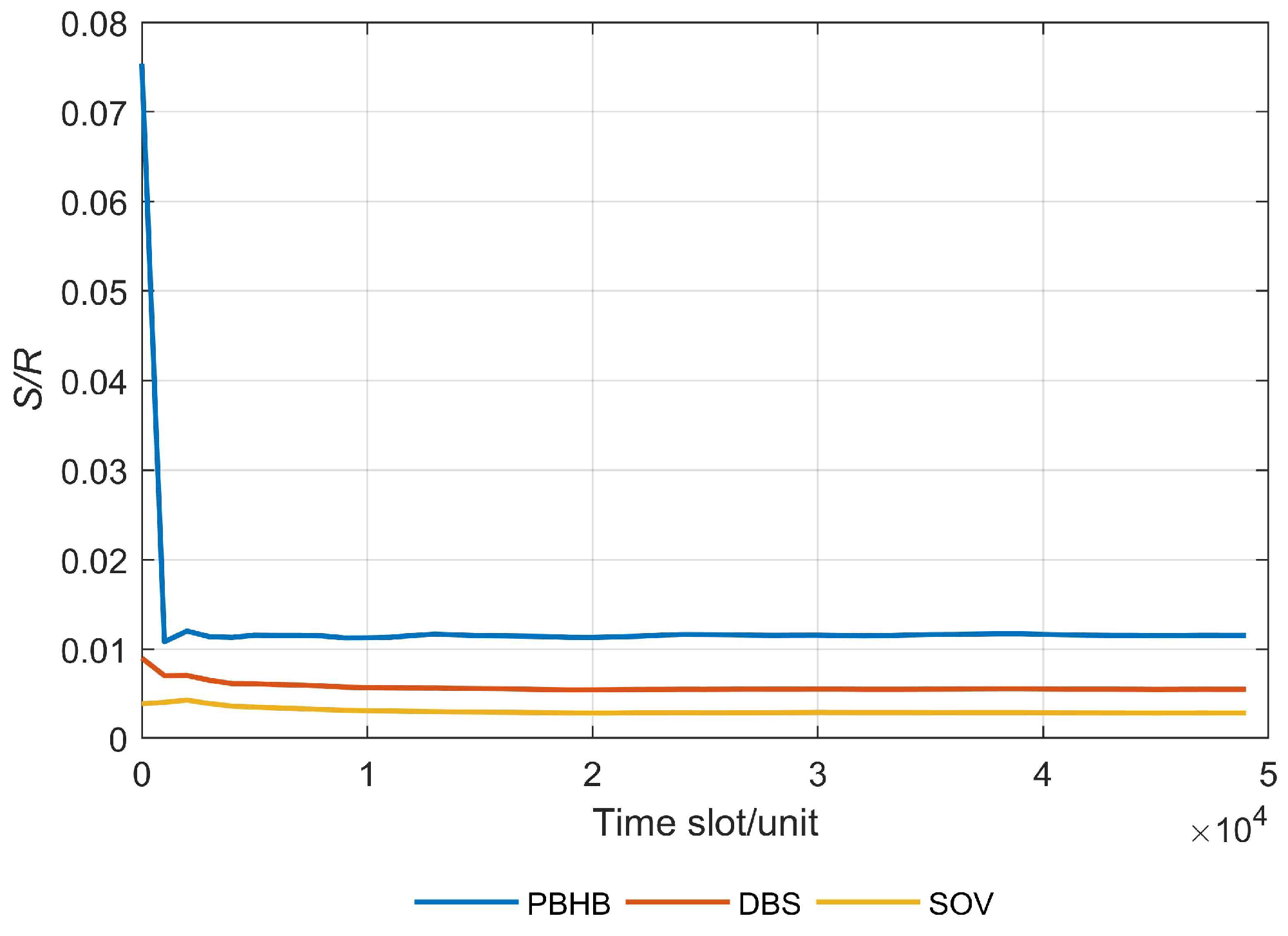
Figure 17 presents the results of the long-term average security-to-protection-resources cost ratio for three different methods. It was observed that PBHB had the highest ratio of long-term average security-to-protection-resources cost at approximately 0.011. DBS then followed, with a ratio of around 0.006. SOV ranked third, with a ratio of around 0.003. This was because PBHB selects the scheme with the highest protection efficiency to deploy a backup VNF, resulting in the highest ratio of long-term average security-to-protection-resources cost. DBS employs a shared backup mechanism to protect all VNFs, albeit with a protection efficiency that is lower than that of PBHB, thus resulting in the second ranking in the ratio of long-term average security-to-protection-resources cost. SOV utilizes a dedicated backup mechanism to protect individual VNFs with the lowest protection efficiency, thus resulting in a third ranking in the ratio of long-term average security-to-protection-resources cost. Additionally, it can be observed that the long-term average security-to-protection-resources cost ratio of the PBHB method sharply decreases in the initial stages of the experiment. This is because the first few SFCs deployed using the PBHB method can meet security requirements without consuming protection resources. Therefore, at the beginning of the experiment, the long-term average security-to-protection-resources cost ratio is high. However, as more SFCs are deployed, more protection resources are needed to meet the security requirements. As a result, the long-term average security-to-protection-resources cost ratio gradually stabilizes over time.
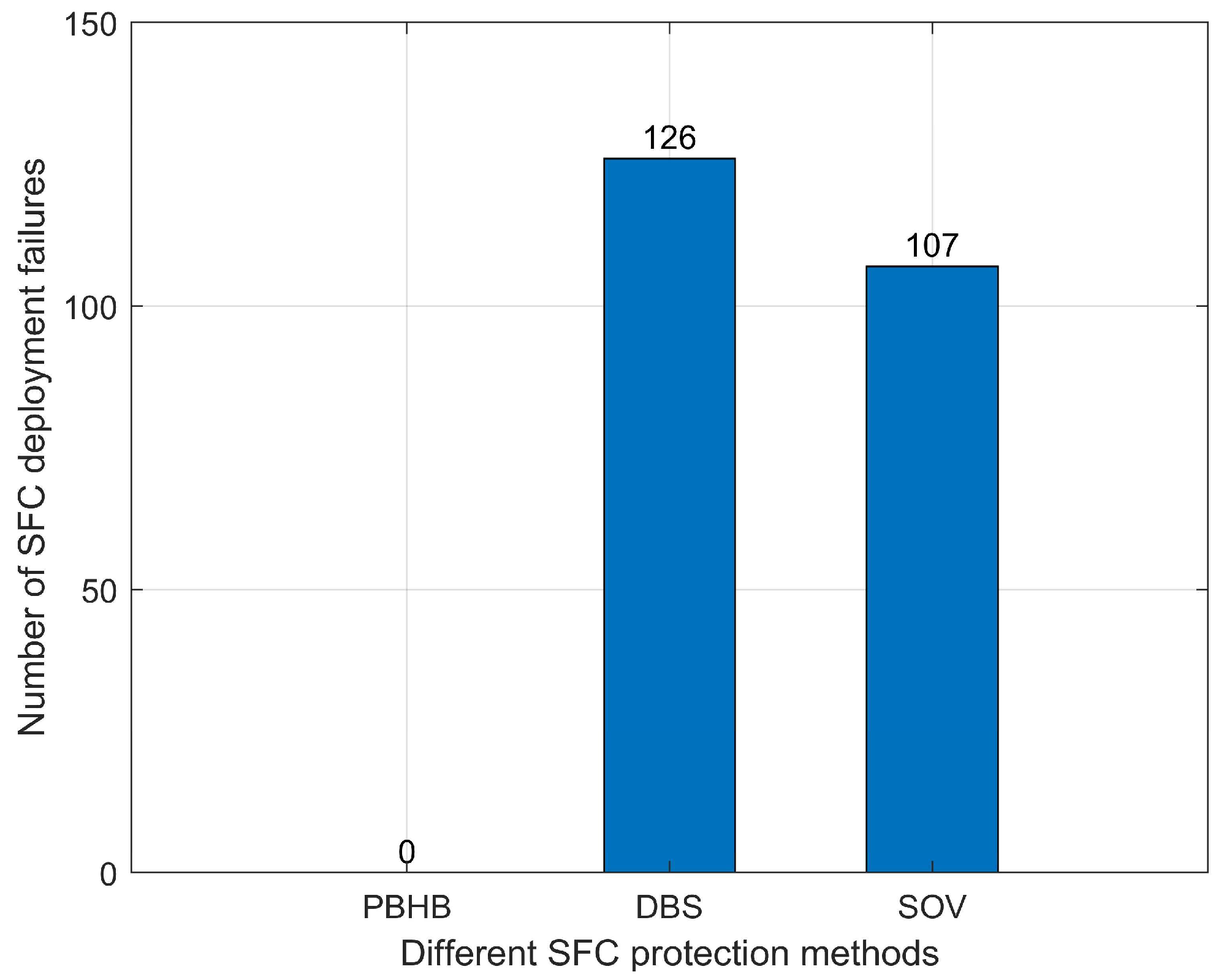
Figure 18 illustrates the number of SFC deployments that failed for three different methods. It shows that the number of failed SFC deployments for PBHB was 0, 126 for DBS, and 107 for SOV. This happened because PBHB provides honeypot technology protection and backup VNF protection for SFCs, resulting in the lowest number of failed SFC deployments. DBS offers shared backup protection for all VNFs and, although the protection efficiency is relatively high, the protection effect provided to each VNF is limited, thus leading to the highest number of failed SFC deployments. SOV provides dedicated protection for VNFs and, although the protection efficiency is lower, the protection effect it provides to each VNF was found to be the most significant, resulting in a lower number of failed SFC deployments compared to DBS.
7. Conclusions
The NFV-based air traffic information network breaks the closed architecture of the tight coupling between hardware and software in traditional networks, thus greatly improving the flexibility of air traffic service deployment. However, deploying multiple VNFs on the same physical platform will expose SFCs to the risk of side-channel attacks, posing security and safety risks to air traffic operations. In response to the network attack risks faced by SFCs in the air traffic information network, this paper proposes an SFC protection method based on honeypots and backup technology (PBHB), which can proactively enhance the security of the network before attacks occur.
The PBHB method first utilizes the TAPD algorithm to deploy the primary VNFs as much as possible on the shortest path between the source and destination endpoints, thus aiming to reduce SFC latency and save link bandwidth resources. Secondly, the RAHDR algorithm is utilized to install honey pot VNFs in physical platforms where the number of hosted VNFs is not less than two, and the deployment status of honey pot VNFs in each physical platform is dynamically updated in real-time according to the lifecycle of the VNFs, aiming to provide the first line of defense for the SFCs. Finally, the BDMPE algorithm was used to implement backup protection for SFCs that still cannot meet security requirements, where the aim is to reduce the cost of protection resources. The simulation experiments demonstrated that the proposed PBHB method in this paper can achieve optimizations in terms of the long-term average revenue–cost ratio, long-term average protection resource cost, long-term average bandwidth cost, and the long-term average security-to-protection-resources cost ratio while ensuring the security and latency of SFCs.
However, while honeypot technology and backup technology can significantly enhance the security of SFCs, they require more redundant resources. Therefore, our next step will focus on the research of VNF migration mechanisms to further achieve comprehensive optimizations of both SFC security and resource cost in air traffic information networks.


