Article

Improved Implementation of Chua’s Circuit on an Active Inductor and Non-Autonomous System

1
School of Integrated Circuits, Shandong University, Jinan 250199, China
2
Shenzhen Research Institute of Shandong University, Shenzhen 518000, China
3
School of Electrical and Electronic Engineering, Nanyang Technological University, Singapore 699010, Singapore
*
Author to whom correspondence should be addressed.
Electronics 2024, 13(13), 2637; https://doi.org/10.3390/electronics13132637
Submission received: 4 June 2024 / Revised: 27 June 2024 / Accepted: 2 July 2024 / Published: 4 July 2024

Abstract

:
Chua’s circuit is a well-established model for studying chaotic phenomena and is extensively implemented in fields like encrypted communication. However, a traditional Chua’s circuit has large volume, high component precision requirements and limited adjustable parameter range, which are not conducive to application. In order to solve these problems, we propose an improved implementation of Chua’s circuit on an active inductor and non-autonomous system. First, we adopt the strategy of using active inductors instead of traditional passive inductors, achieving the miniaturization of the circuit and improving the accuracy of inductance. In addition, we present the theory of substituting non-autonomous systems for classical autonomous systems to reduce the requirements for the accuracy of components and improve the robustness of the circuit. Lastly, we connect the extension resistor in parallel with Chua’s diode to optimize circuit structure, thereby increasing the range of the adjustable parameter. Based on the three improvements above, experiments have shown that the average maximum error tolerance of components of our improved design has been increased from 1.88% to 7.38% when generating a single vortex, and from 4.73% to 12.61% when generating a double vortex, compared with the traditional Chua’s circuit. The range of the adjustable parameter has been increased by 195.83% and 36.98%, respectively, when generating a single vortex and double vortex. In summary, our improved circuit is more practical than the traditional Chua’s circuit and has good application value.

1. Introduction

Chua’s circuit is widely recognized as a significant example among typical chaotic signal generation circuits. In comparison to other nonlinear circuits such as a Van der Pol oscillator and Colpitts oscillator, Chua’s circuit is the simplest design in structure, since it has only five circuit elements. However, Chua’s circuit is dynamically the most complex among all nonlinear circuits and systems, described by a 21-parameter family of continuous odd-symmetric piecewise-linear vector fields [1]. Due to characteristics of nonlinearity, determinism, and sensitivity to initial conditions, Chua’s circuit is widely used in fields such as encrypted communication, random number generation, and sensors [2,3,4]. Therefore, studying how to improve the design to make Chua’s circuit more favorable to application is of great significance.
Currently, the integration of a circuit is an important trend in electronics. When designing integrated circuits, the traditional passive inductor used in Chua’s circuit has large volume and is accompanied by parasitic series equivalent resistance [5], making it difficult to achieve integration. To address this issue, Demirkol et al. proposed a method of using active components to form active inductors which can theoretically achieve miniaturization and precise control [6]. This theory has been accepted by most scholars and a variety of active inductors have been designed. For example, Xiaofei Duan et al. from the Chinese Academy of Sciences introduced a lossless active inductance type and integrated it into Chua’s circuit [7]. However, their design suffered from poor waveform quality, even resulting in incomplete double vortex generation. Among numerous active inductors, the Riordan gyrator is widely recognized due to its simple structure and stable performance. For instance, Francisco et al. designed a floating meminductor emulator on a Riordan gyrator, and Ananda et al. proposed a high-frequency meminductor emulator using a Riordan gyrator, both with good performance [8,9]. For these reasons, we adopted the strategy of using active inductors instead of traditional passive inductors and the Riordan gyrator was adopted in this improved implementation of Chua’s circuit.
Efforts have been made to improve the circuit structure in multiple aspects, especially focusing on Chua’s diodes, to advance the application of Chua’s circuit [10,11]. For example, Elwakil et al. combined attractive features of the current feedback op amp (CFOA) operating in both voltage and current modes to construct the active three-segment voltage-controlled nonlinear resistor. This reduces the component count and extends the chaotic spectrum to higher frequencies [12]. By replacing the Chua’s diode with a first-order hybrid diode circuit, Bocheng Bao et al. presented a fourth-order modified Chua’s circuit which exhibits complicated nonlinear phenomena including self-excited attractors, coexisting self-excited attractors, hidden attractors, and coexisting hidden attractors [13]. Additionally, Fei Yu et al. constructed a compound hyperbolic tangent–cubic nonlinear function in a canonical Chua’s circuit, and the proposed multi-scroll Chua’s circuit also exhibited rich dynamic behaviors, like coexisting multiple attractors, transient period, intermittent chaos, and offset boosting [14]. While previous studies have primarily focused on modifying the circuit to generate diverse dynamic behaviors, little attention has been given to improve circuit reliability, which is quite crucial for practical applications.
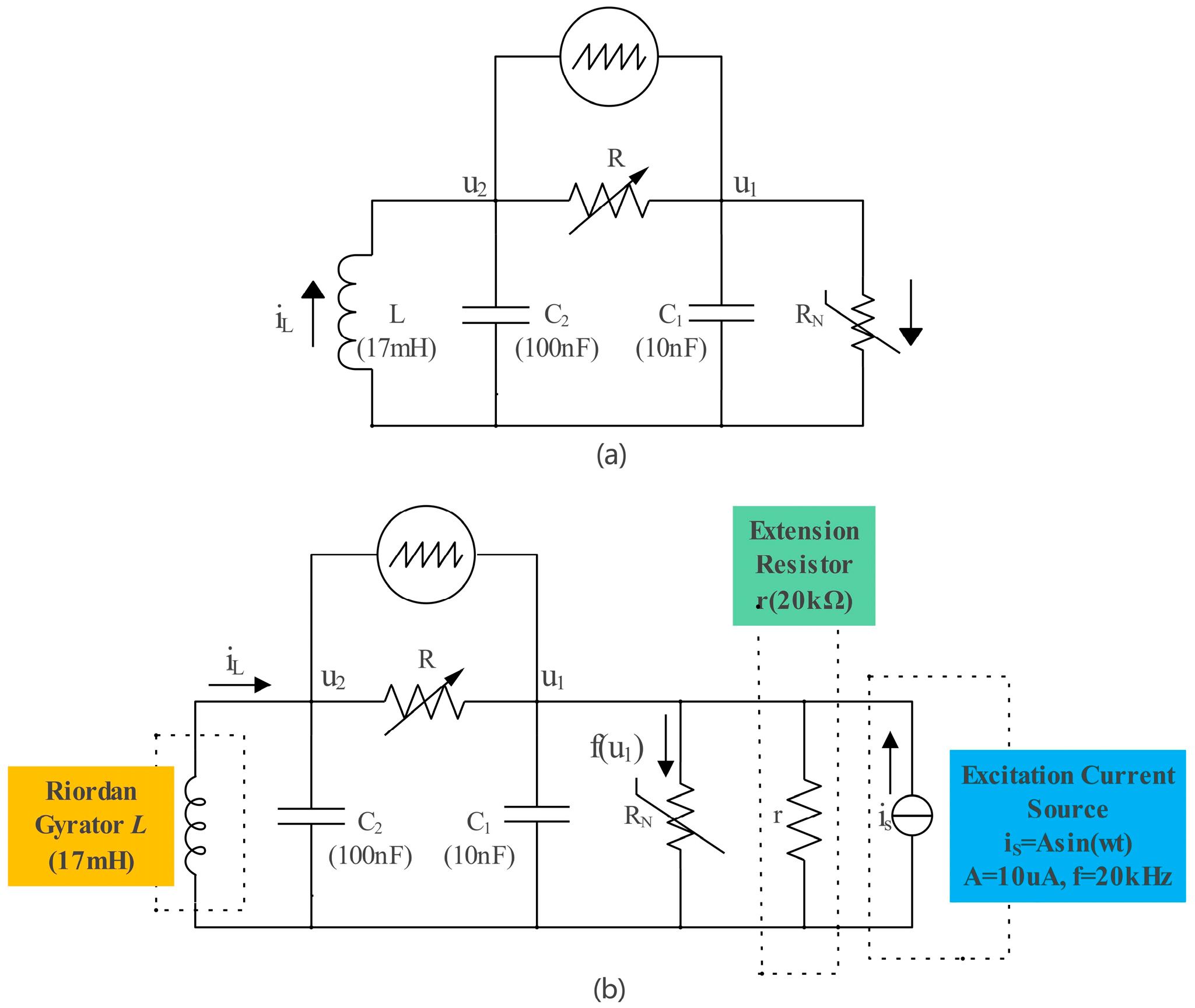
In applications, Chua’s circuit manifests in two forms. The first form involves selecting resistors with different resistance values through switch to generate different signals, as is shown in Figure 1a [15,16]. Despite straightforward operation, this method suffers from poor robustness as Chua’s circuit is extremely sensitive to initial conditions and has high requirements for component accuracy. The second form involves changing the value of the resistor R by sliding the rheostat, resulting in a single and double vortex, as is shown in Figure 1b [17]. Although this design is robust, the application is limited by the small range of the adjustable resistor R.
Due to the defects in the structure of the traditional Chua’s circuit, there are weaknesses in the above two forms. To study this issue, Yeong-Chan Chang et al. made an attempt by using a hybrid adaptive-robust tracking control scheme to study nonlinear chaotic Chua’s circuits involving plant uncertainties and external disturbances [18], but it did not fundamentally improve circuit robustness.
In order to compensate for the structural defects of the traditional Chua’s circuit, an improved implementation to the structure of Chua’s circuit is proposed in this paper. The main improvements we proposed are summarized as follows:
  • We adopt the strategy of using active inductors instead of traditional passive inductors. Since the volume of the op amp and resistors are much smaller than that of the inductor coils, this design enables the miniaturization and integration of circuits. Meanwhile, the accuracy of the inductor is greatly improved because the inductance value can be controlled precisely by adjusting the resistance value.
  • We present the theory of substituting non-autonomous systems for classical autonomous systems. According to the state equation of the circuit and the chaotic conditions of a system, the excitation current source we added can reduce the requirements for the accuracy of components and improve the robustness of the circuit.
  • We connect the extension resistor in parallel with Chua’s diode to optimize the circuit structure, increasing the range of the adjustable parameter.
In summary, the improvements above compensate for the defects of the Chua’s circuit structurally and improve the reliability. As a result, the shortcomings of the two forms of Chua’s circuit can be perfectly solved. For ease of presentation and evaluation of the robustness of the circuit, we defined several concepts in this paper [19,20].
  • The resistor connected in parallel with Chua’s diode is termed the extension resistor due to its functional role.
  • The maximum error tolerance Y i of component y i is defined as Y i = Δ m y i m y i × 100 % . m y i is the standard value of component y i and Δ m y i is the maximum allowable deviation of component y i .
  • The average maximum error tolerance X of components y 1 , y 2 y n is defined as X = i = 1 n Y i n .
  • In the context of the “range of the adjustable parameter”, the parameter refers specifically to the adjustable resistor R connecting capacitors C 1 and C 2 , and the range refers specifically to the resistance that can create chaos in a circuit.
It is important to note that the excitation current source is considered as part of the signal generation circuit in this paper. However, some scholars suggest that when the amplitude of the excitation current source significantly exceeds what is used in this paper, it can be regarded as the coupling of two systems with the chaotic generation circuit, and changing the amplitude can produce different types of sudden oscillations [21].
The remainder of the paper is organized as follows. Section 2 reviews the traditional Chua’s circuit. Section 3 introduces this improved implementation of Chua’s circuit on an active inductor and non-autonomous system. Section 4 compares two circuits theoretically. Section 5 conducts experimental testing and comparison on the two circuits. Conclusions are drawn in Section 6.

2. Traditional Chua’s Circuit

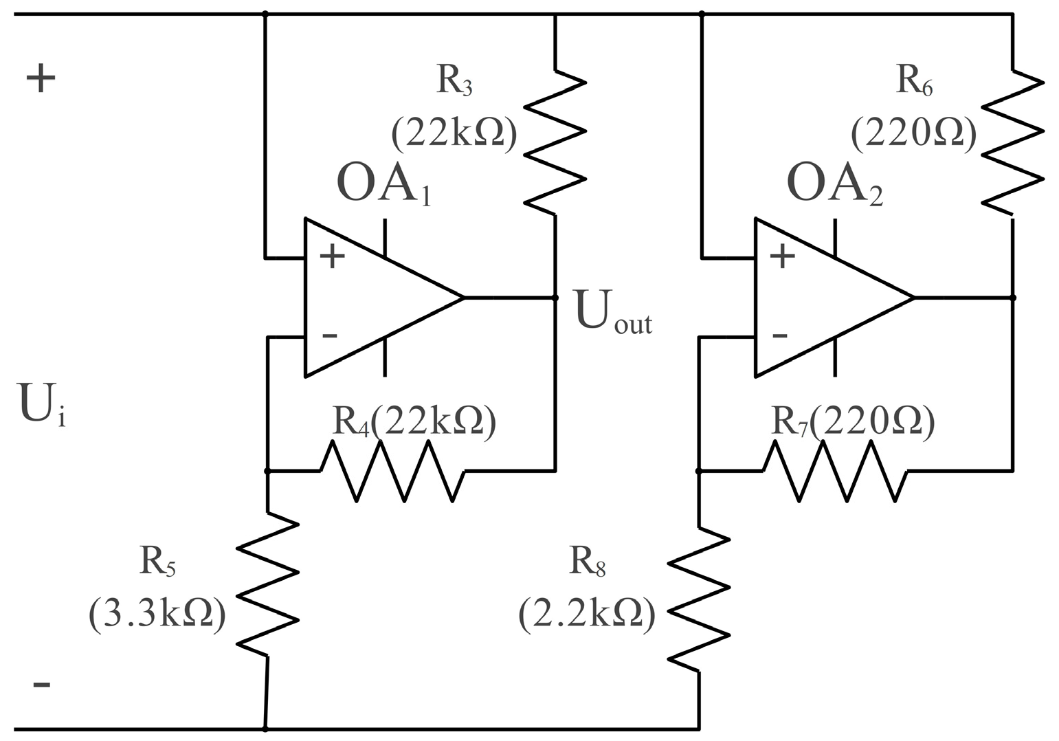
A traditional Chua’s circuit consists of a passive inductor L, two capacitors C 1 and C 2 , an adjustable resistor R, and Chua’s diode R N [22,23], as is shown in Figure 1c. The Chua’s diode R N is shown in Figure 2.
According to Kirchhoff’s Current Law and Kirchhoff’s Voltage Law, the state equation of the circuit can be described as
d u 1 d t = u 2 u 1 R C 1 f ( u 1 ) C 1 d u 2 d t = u 1 u 2 R C 2 + i L C 2 d i L d t = u 2 L
f ( u 1 ) = G b u 1 + 0.5 ( G a G b ) [ | u 1 + B P | | u 1 B P | ] ,
where f ( u 1 ) is the current flowing through the Chua’s diode, G a is the inner interval conductivity, G b is the outer interval conductivity, and B P is the turning point voltage of the inner and outer intervals. The self-excited circuit system described in (1) and the nonlinear resistor described in (2) are sources of chaos in Chua’s circuit. Moreover, parameters in Figure 1 and Figure 2 are presented according to the specifications proposed by American electrical engineer Leon O. Chua in 1983. Since then, this specification has been used in most practical applications of Chua’s circuit [24,25,26,27].

3. Improved Implementation of Chua’s Circuit on an Active Inductor and Non-Autonomous System

This improved implementation of Chua’s circuit adopts the strategy of using active inductors instead of traditional passive inductors. Among numerous active inductors, we took into account the structure, performance, and stability, finally choosing the Riordan gyrator. Additionally, we present the theory of using non-autonomous systems instead of classical autonomous systems, and the excitation current source is added. Lastly, the extension resistor is connected in parallel with the Chua’s diode. This improved implementation of Chua’s circuit is shown in Figure 3.
According to Kirchhoff’s Current Law and Kirchhoff’s Voltage Law, the state equation of the circuit can be described as
d u 1 d t = u 2 u 1 R C 1 f ( u 1 ) C 1 + i S u 1 r C 1 d u 2 d t = u 1 u 2 R C 2 + i L C 2 d i L d t = u 2 L ,
where L refers to the equivalent inductance value of the Riordan gyrator. Please kindly note that the non-autonomous system described in (3) is the source of the circuit’s chaotic phenomena, and is different from the autonomous system of traditional Chua’s circuit. Parameters of the extension resistor and the excitation current source will be discussed in the following part.

3.1. Extension Resistor r

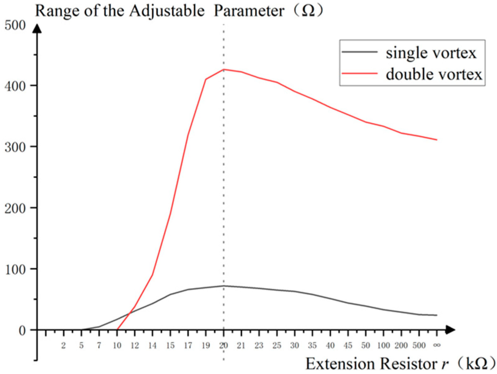
The extension resistor r is a linear resistor parallel to the Chua’s diode. It plays a crucial role in altering the range of the adjustable parameter, thereby inducing chaos in the circuit by modifying the circuit’s state equation. To determine the most suitable value of extension resistor r, the sine excitation current source i S was selected to conduct a series of experiments, with an amplitude of 10   μA and a frequency of 20   kHz . According to the experiment results, the range of the adjustable parameter that causes chaos in the circuit with the varied extension resistor r is shown in Figure 4.
As is shown in Figure 4, when the resistance of the extension resistor r approaches 20   k Ω , the range of the adjustable parameter for both the single vortex and the double vortex reaches the maximum. Therefore, r = 20   k Ω was determined. It is also notable that there will be no double vortex when the resistance value of r is less than 10   k Ω and chaos will not appear when it is less than 5   k Ω .

3.2. Excitation Current Source i S

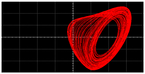
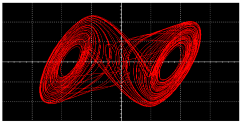
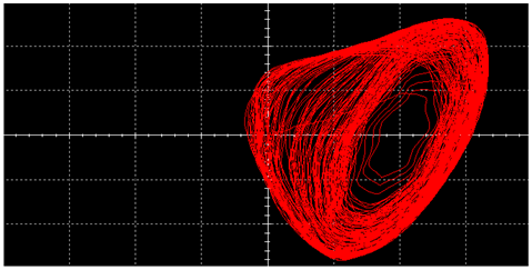
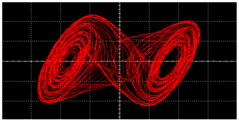
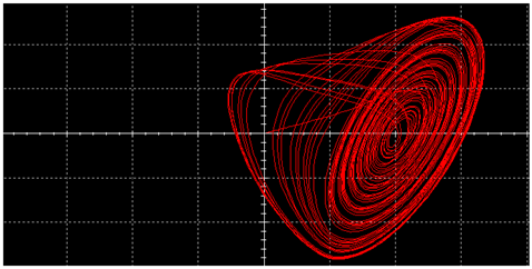
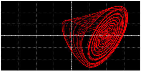
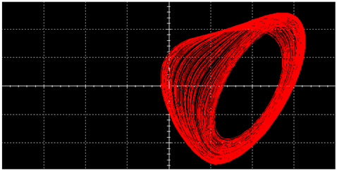
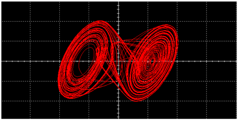
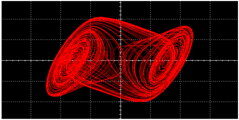
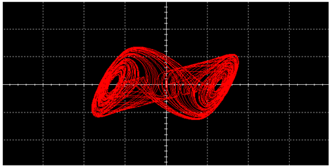
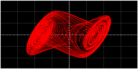
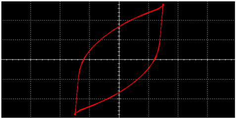
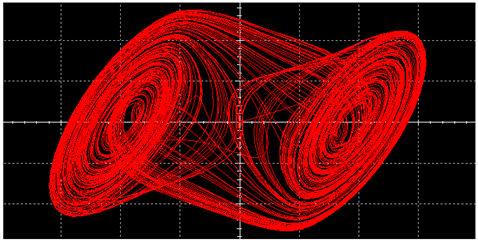
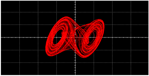
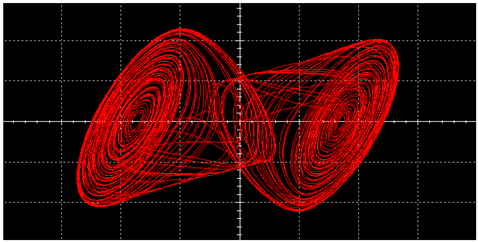
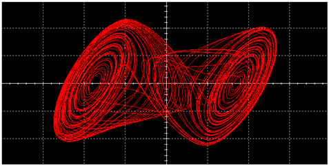
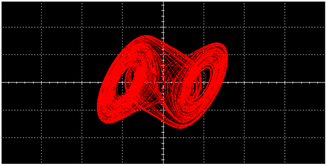
The excitation current source i S can reduce the requirements for the accuracy of the components and improve circuit robustness. We selected the extension resistor r = 20   k Ω and compared the chaotic signals under different types of excitation current sources; sine wave, square wave, and triangular wave, whose amplitude A = 10   μA and frequency f = 20   kHz , as is shown in Table 1.
The results confirm that the chaotic signal is the smoothest when sine wave is used, which is quite important for applications such as encrypted communications. For chaotic encrypted communication systems, a smoother chaotic signal offers great advantages in terms of synchronization ease, noise resistance, spectral utilization, hardware simplicity, transmission efficiency, and BER performance [28,29,30]. Therefore, we chose the sine wave in our experiment. Next, we will discuss parameters of the sine wave excitation current source.
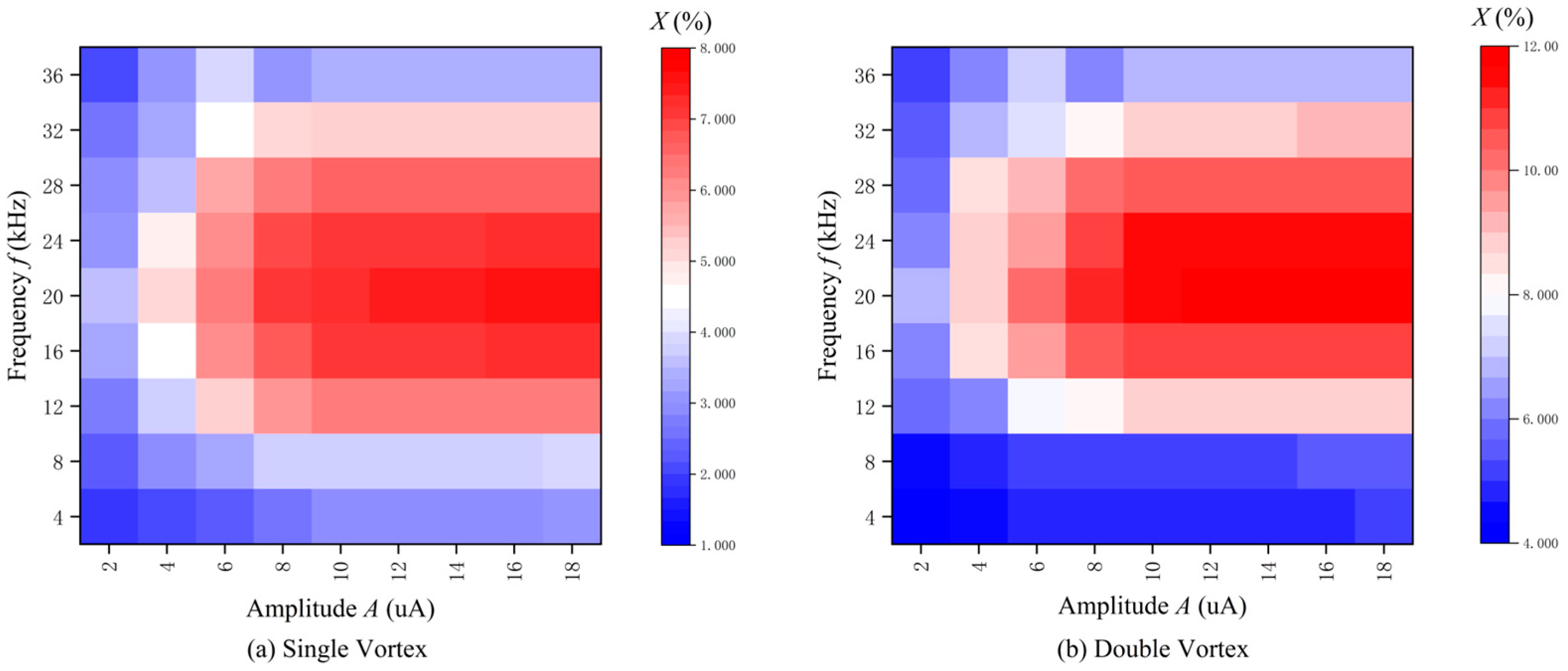
In order to determine the amplitude A and frequency f, we performed a variation in amplitude for different frequencies and measured the average maximum error tolerance X of components L, C 1 , and C 2 for corresponding conditions, as is shown in Figure 5.
From Figure 5, it can be easily observed that the larger the amplitude A, the greater the average maximum error tolerance X of components L, C 1 , and C 2 becomes. However, there is no significant increase in tolerance when A > 10   μA , and the chaotic signal waveform is no longer smooth and will transform into polygons when the amplitude A is larger. The amplitude A = 10   μA is determined based on the above reasons. On the other hand, X reaches its maximum when the frequency f is around 20   kHz , so the frequency f = 20   kHz is determined.

4. Theoretical Comparison

Compared with the traditional Chua’s circuit, this improved implementation of Chua’s circuit has three improvements in structure: one is the change from passive inductor to active inductor, another is the improvement from an autonomous system to a non-autonomous system, and the other is the addition of the extension resistor. Since the latter two improved theoretical analyses require the Lyapunov exponent, they are put together for theoretical comparisons.

4.1. Change from Passive Inductor to Active Inductor

The inductance of traditional passive inductors depends on the distribution of the surrounding dielectrics and the number, the size, and the shape of the wound coil. In practice, not only is it bulky and difficult to adjust, but it is also accompanied by parasitic resistance, which can cause additional voltage drops and power losses, resulting in large errors.
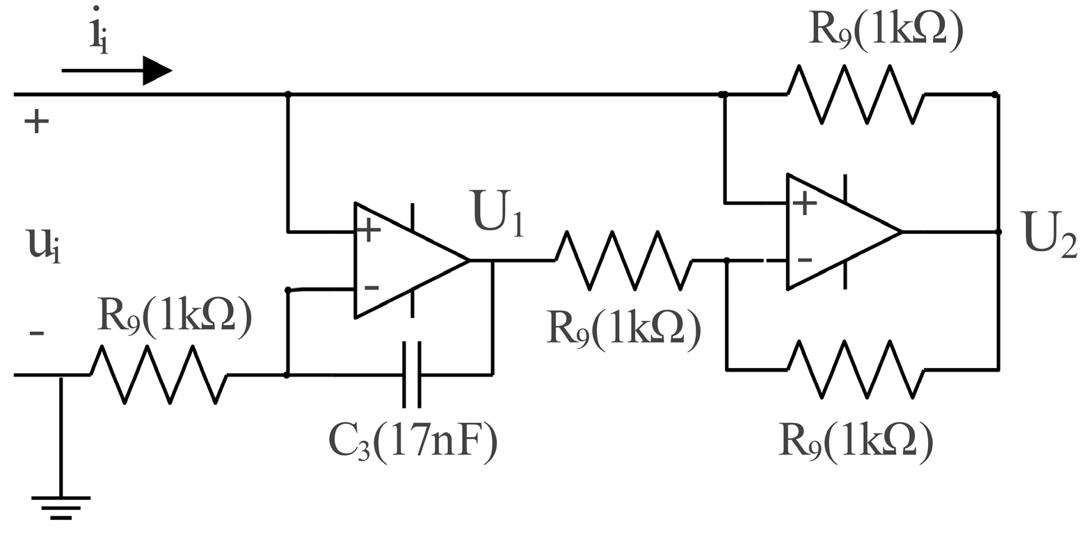
The strategy of using active inductors instead of traditional passive inductors can be a good solution to the above problems. The Riordan gyrator consists of two operational amplifiers, four resistors, and a capacitor, with a simple structure and high stability [8,31], as is shown in Figure 6.
According to the characteristics of the operational amplifier, the state equation of the Riordan gyrator can be described as (4). Based on (4), we can derive the input impedance Z of the circuit, as shown in (5), and the equivalent inductance value L, as shown in (6).
u i U 2 R 9 = U 1 u i R 9 i i = u i U 2 R 9 U 1 = ( 1 + 1 j w R 9 C 3 ) u i
Z ( j w ) = u i i i = j w R 9 2 C 3
L = R 9 2 C 3
According to (4)–(6), the inductance value of the Riordan gyrator in this improved implementation of Chua’s circuit can be precisely controlled by adjusting the value of the resistors. Moreover, this design eliminates parasitic resistance, with high accuracy and reliability, and its small size further facilitates integration. In this circuit (Figure 6), L = 17 mH , therefore, R 9 could be derived as 1   k Ω and C 3 could be derived as 17 nF .

4.2. Improvement from an Autonomous System to a Non-Autonomous System and the Addition of an Extension Resistor

A traditional Chua’s circuit has high component precision requirements and limited adjustable parameter range, especially when generating a single vortex. According to the state equation of the circuit and the chaotic conditions of a system, the theory of substituting non-autonomous systems for classical autonomous systems can reduce the requirements for the accuracy of the components, and the extension resistor parallel to the Chua’s diode can increase the range of the adjustable parameter effectively. To determine whether a system is chaotic and prove the above theory, we introduced the Lyapunov exponent.
Chaotic systems exhibit a trademark “sensitive dependence on initial conditions” (SDIC). This means that very small perturbations will cause the resulting trajectories to separate exponentially quickly. Lyapunov exponents directly measure SDIC by quantifying the exponential rates at which neighboring orbits on an attractor diverge (or converge) as the system evolves in time. Dissipative deterministic systems that exhibit at least one positive Lyapunov exponent are defined as “chaotic”. Therefore, to determine whether the circuit system is chaotic, we need to calculate the maximum Lyapunov exponent in the system [32,33,34].
Then, we calculate the Lyapunov exponents in this improved implementation of Chua’s circuit. We can obtain (7) by deforming (3).
C 1 d x d t + f ( x ) = y x R + i S C 2 d y d t + y x R = z L d z d t = y
f ( x ) = G b x + 0.5 ( G a G b ) [ | x + B P | | x B P | ]
By assuming x = f 1 ( i S ) , y = f 2 ( i S ) , z = f 3 ( i S ) and taking a point i 0 of i S , the process of calculating the Lyapunov exponents is as follows:
a 0 = i 0 , b 0 = i 0 , c 0 = i 0
a 1 = f 1 ( a 0 ) , b 1 = f 2 ( b 0 ) , c 1 = f 3 ( c 0 )
⋯⋯
a n 1 = f 1 ( a n 2 ) , b n 1 = f 2 ( b n 2 ) , c n 1 = f 3 ( c n 2 )
The Lyapunov exponents in this improved implementation of Chua’s circuit are
λ 1 = lim r 1 r k = 0 r 1 ln | f 1 ( a k ) | λ 2 = lim r 1 r k = 0 r 1 ln | f 2 ( b k ) | λ 3 = lim r 1 r k = 0 r 1 ln | f 3 ( c k ) |
We assume that
λ n e w = max { λ 1 , λ 2 , λ 3 }
Similar to the above process, the Lyapunov exponents of the traditional Chua’s circuit are
λ 4 = lim r 1 r k = 0 r 1 ln | f 4 ( a k ) | λ 5 = lim r 1 r k = 0 r 1 ln | f 5 ( b k ) | λ 6 = lim r 1 r k = 0 r 1 ln | f 6 ( c k ) |
We assume that
λ o l d = max { λ 4 , λ 5 , λ 6 }
To answer the problem of why this design can reduce the requirements for the accuracy of components and increase the range of the adjustable parameter, we will calculate the maximum Lyapunov exponent.

4.2.1. Robustness

When generating a single vortex, the maximum Lyapunov exponent of the circuit with 5% error in components L, C 1 , and C 2 , respectively, is shown in Table 2. According to the analysis of Table 2, the maximum Lyapunov exponent of the traditional Chua’s circuit could be less than zero when there is a 5% error in components L, C 1 , and C 2 , respectively, resulting in no chaos being generated. By comparison, the maximum Lyapunov exponents of this improved implementation of Chua’s circuit are all greater than zero, which means that the chaotic signal can still be generated stably.
When generating a double vortex, the maximum Lyapunov exponent of the circuit with a 5% error in components L, C 1 , and C 2 , respectively, is shown in Table 3. According to Table 3, the maximum Lyapunov exponent of the traditional Chua’s circuit may be less than zero and cannot generate chaos when there is a 5% error in C 1 . In contrast, the maximum Lyapunov exponents of this improved implementation of Chua’s circuit are all greater than zero, and the circuit can still generate chaos.
Based on the calculations above, this improved implementation of Chua’s circuit has lower requirements for the accuracy of components and higher robustness to the deviation of components’ values than the traditional Chua’s circuit.

4.2.2. Range of Adjustable Parameters

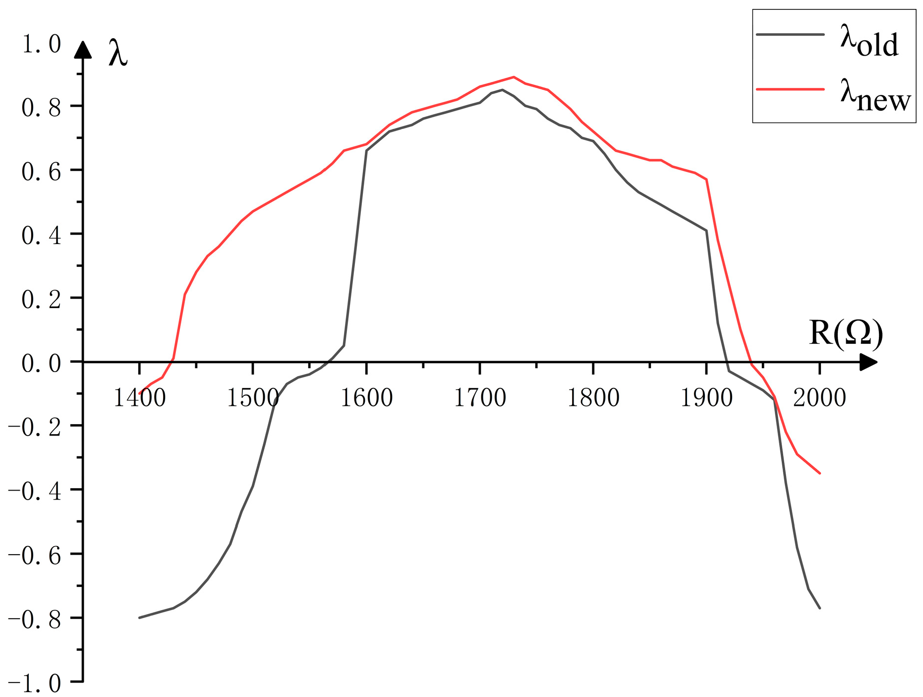
We changed the value of the adjustable resistor and calculated the maximum Lyapunov exponent for different R corresponding systems, as is shown in Figure 7. The result shows that λ o l d > 0 is a sufficient but unnecessary condition for λ n e w > 0 . Therefore, this improved Chua’s circuit extends the range of chaotic operation, reducing the inconvenience and facilitating the application of this circuit.

5. Experimental Comparison

In the experiment, the digital oscilloscope we used was a GDS-1104R made by GWINSTEK, in Suzhou, China, with a bandwidth of 100 MHz and a sampling rate of 1 GS/s, and the signal generator we used was a MFG-2260MRA made by GWINSTEK, in Suzhou, China. Circuit components were manufactured by RISYM, in Shenzhen, China. Regarding how the oscilloscope is connected to the final circuit, channel A and channel B of the oscilloscope measured the circuit nodes with voltages u 2 and u 1 , respectively. Then, we set the oscilloscope mode to u 2 u 1 , displaying the waveforms. The external test circuits of traditional Chua’s circuit and the improved implementation of Chua’s circuit are shown in Figure 8a and Figure 8b, respectively.

5.1. Robustness When Generating a Single Vortex

5.1.1. Test Case 1 ( R = 1890   Ω )

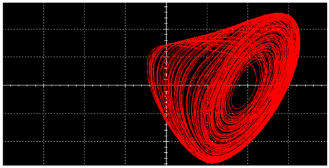
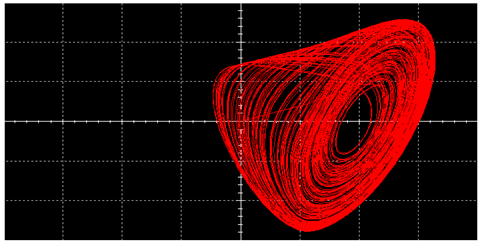
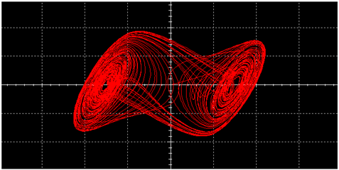
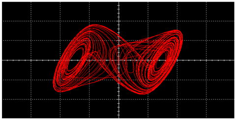
When a single vortex is generated stably, the maximum error tolerance Y of components L, C 1 , and C 2 , respectively, are shown in Table 4. When there is a 5% error in components L, C 1 , and C 2 , respectively, signals generated by the circuit are shown in Table 5.

5.1.2. Test Case 2 ( R = 1900   Ω )

When a single vortex is generated stably, the maximum error tolerance Y of components L, C 1 , and C 2 , respectively, is shown in Table 6. When there is a 5% error in components L, C 1 , and C 2 , respectively, signals generated by the circuit are shown in Table 7.

5.1.3. Test Case 3 ( R = 1910   Ω )

When a single vortex is generated stably, the maximum error tolerance Y of components L, C 1 , and C 2 , respectively, is shown in Table 8. When there is a 5% error in components L, C 1 , and C 2 , respectively, signals generated by the circuit are shown in Table 9.

5.1.4. Brief Summary

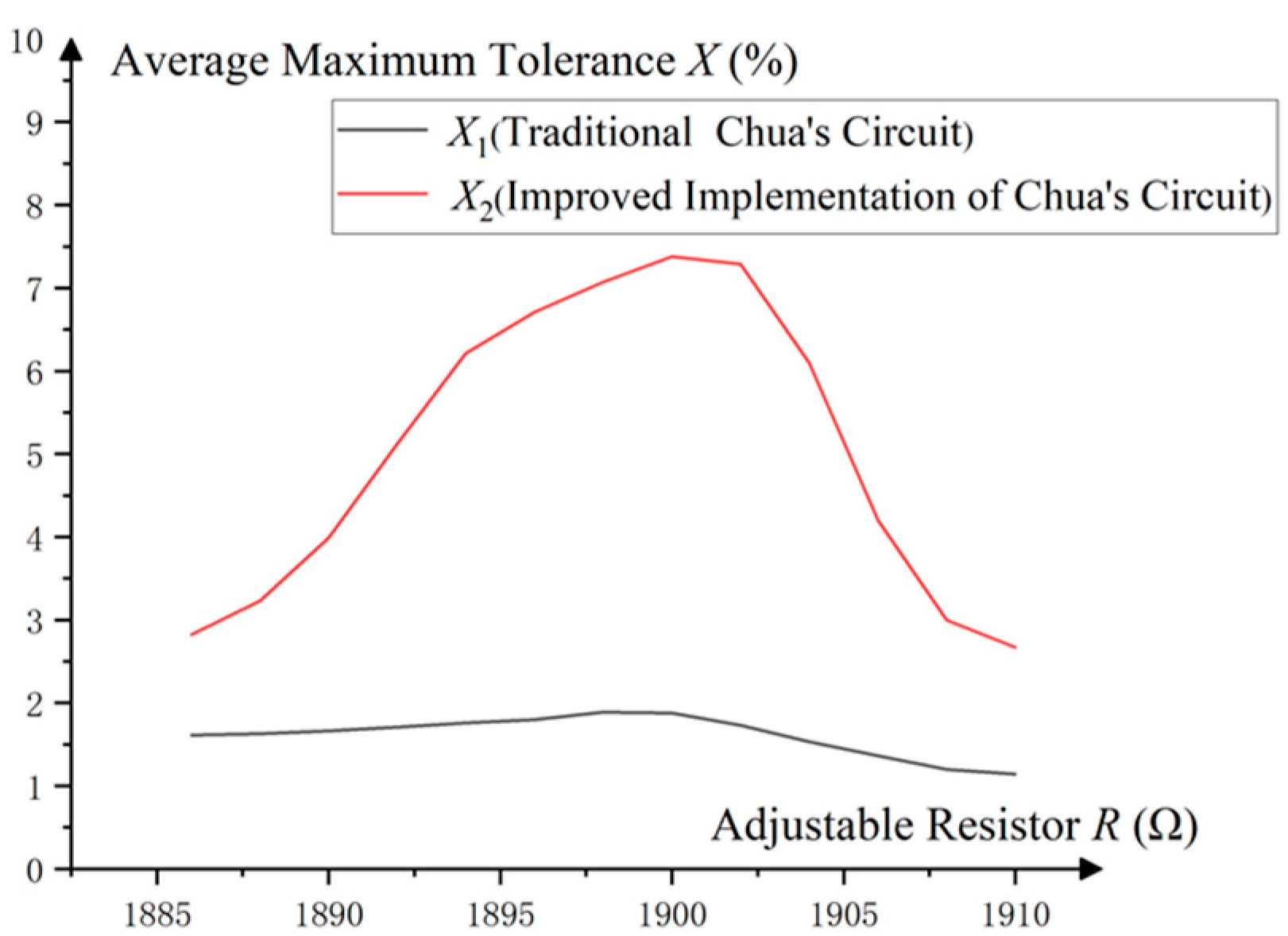
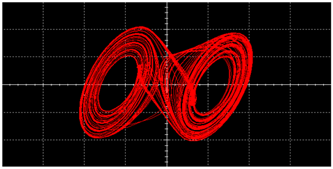
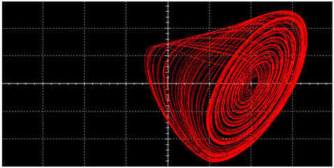
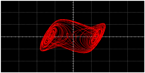
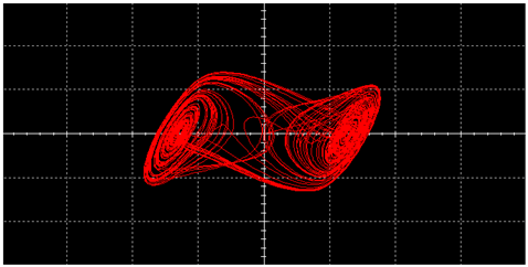
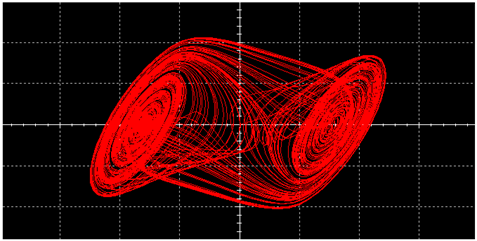
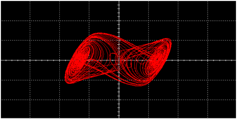
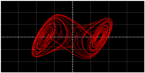
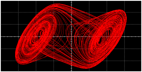
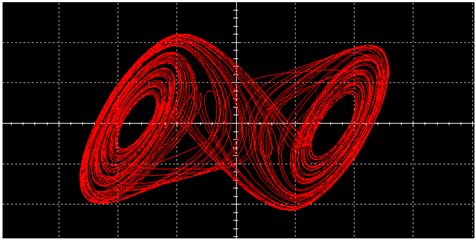
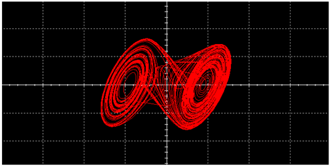
The results above verify that the single vortex generated by the traditional Chua’s circuit could evolve into a double vortex or degenerate into a periodic motion in many component error cases, but the improved implementation of Chua’s circuit can still generate a stable single vortex under the same conditions. The average maximum error tolerance X of components L, C 1 , and C 2 for different adjustable resistors R is shown in Figure 9.
According to Figure 9, the average maximum error tolerance X of components L, C 1 , and C 2 in the improved implementation of Chua’s circuit is about three times that in the traditional Chua’s circuit and is increased from 1.88% to 7.38% under typical parameters when generating a single vortex.

5.2. Robustness When Generating a Double Vortex

5.2.1. Test Case 1 ( R = 1600   Ω )

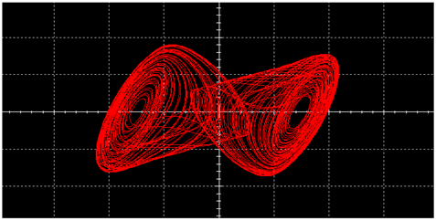
When a double vortex is generated stably, the maximum error tolerance Y of components L, C 1 , and C 2 , respectively, is shown in Table 10. When there is a 5% error in components L, C 1 , and C 2 , respectively, signals generated by the circuit are shown in Table 11.

5.2.2. Test Case 2 ( R = 1700   Ω )

When a double vortex is generated stably, the maximum error tolerance Y of components L, C 1 , and C 2 , respectively, is shown in Table 12. When there is a 5% error in components L, C 1 , and C 2 , respectively, signals generated by the circuit are shown in Table 13.

5.2.3. Test Case 3 ( R = 1800   Ω )

When a double vortex is generated stably, the maximum error tolerance Y of components L, C 1 , and C 2 , respectively, is shown in Table 14. When there is a 5% error in components L, C 1 , and C 2 , respectively, signals generated by the circuit are shown in Table 15.

5.2.4. Brief Summary

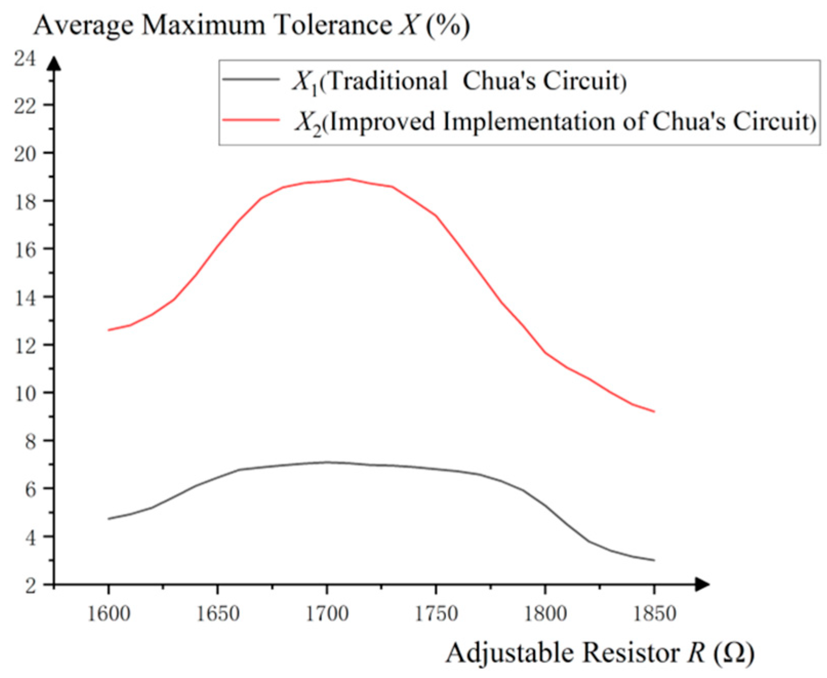
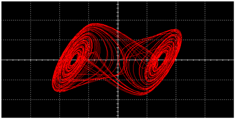
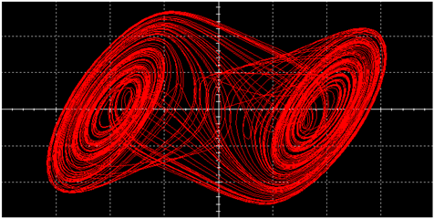
The experiments above indicate that in many component error cases, the double vortex generated by the traditional Chua’s circuit could diverge or degenerate into a single vortex, but the improved implementation of Chua’s circuit can still generate a stable double vortex. The average maximum error tolerance X of components L, C 1 , and C 2 for different adjustable resistors R is shown in Figure 10.
According to Figure 10, the average maximum error tolerance X of components L, C 1 , and C 2 in the improved implementation of Chua’s circuit is about three times that in the traditional Chua’s circuit and is increased from 4.73% to 12.61% under typical parameters when generating a double vortex.

5.3. Range of Adjustable Parameters

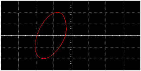
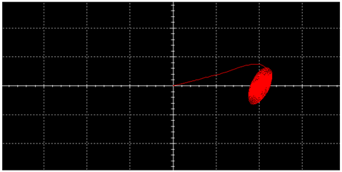
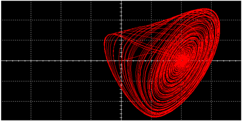
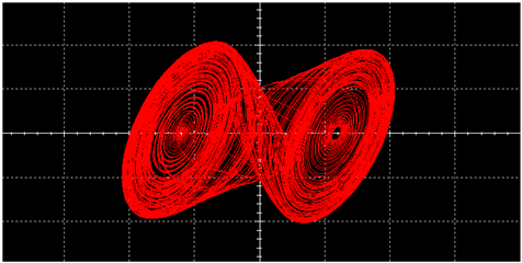
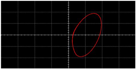
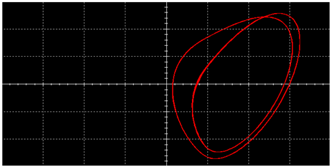
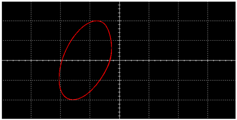
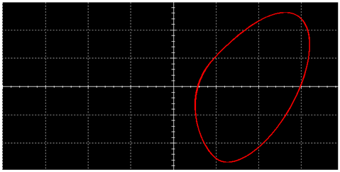
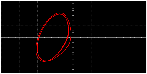
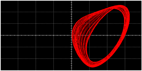
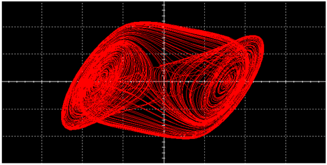
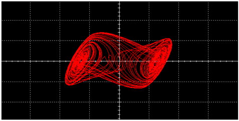
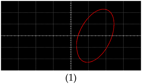
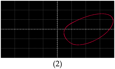
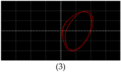
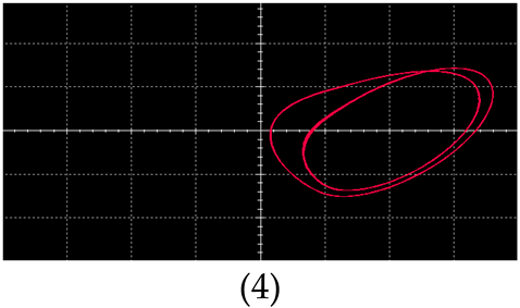
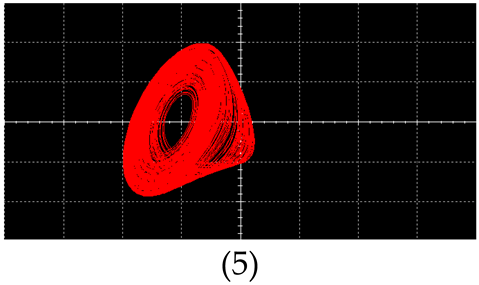
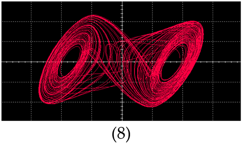
In Chua’s circuit, when the adjustable resistor R is changed from large to small, the circuit produces the following signals in order: unstable bright spot; periodic motion (multiply periodic motion); single vortex; double vortex; divergence. For ease of analysis, we set up the following:
Point 1: Critical point of transition from unstable bright spot to periodic motion (multiply periodic motion).
Point 2: Critical point of transition from periodic motion (multiply periodic motion) to single vortex.
Point 3: Critical point of transition from single vortex to double vortex.
Point 4: Critical point of transition from double vortex to divergence.
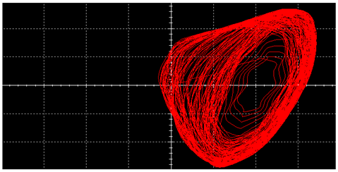
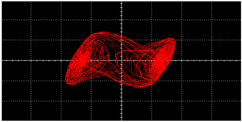
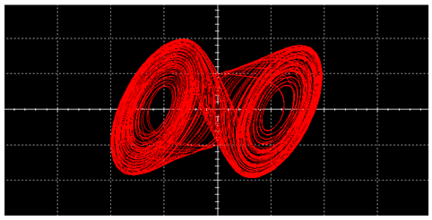
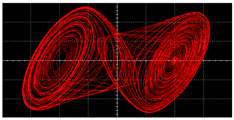
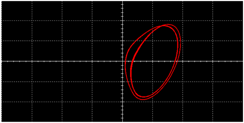
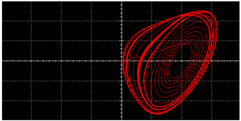
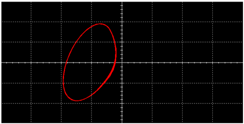
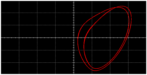
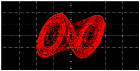
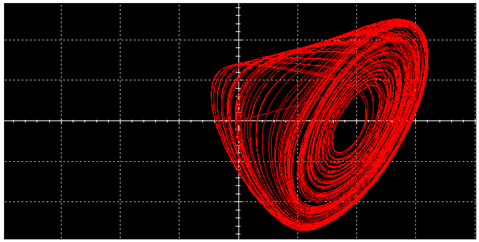
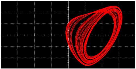
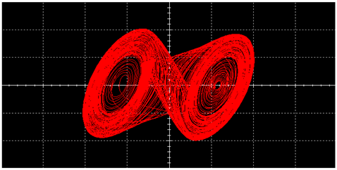
The critical points of the traditional Chua’s circuit and this improved implementation of Chua’s circuit are shown in Table 16. Settings for images above are as shown in Table 17.
According to Table 16, the range of the adjustable parameter R is 24   Ω for generating a single vortex and 311   Ω for generating a double vortex in a traditional Chua’s circuit. By comparison, this improved implementation of Chua’s circuit generates a single vortex and double vortex with adjustable parameter ranges of 71   Ω and 426   Ω , increasing by 195.83% and 36.98%, respectively, making it more convenient to adjust the resistor R to generate different signals.

5.4. Summary of the Experimental Comparison

In practice, parameter perturbations can be caused by many reasons, such as errors caused by production processes and parameter mismatches caused by environmental temperature and humidity. Corresponding to that, robustness, the ability of a circuit system to resist these factors, is quite important for circuit stability and utility. Experiments proved that the robustness of this improved implementation of Chua’s circuit is significantly better than that of the traditional Chua’s circuit, and the average maximum tolerance for component errors is increased by 5.50% and 7.88%, respectively, under typical parameters when generating a single vortex and double vortex.
At the same time, the range of the adjustable parameter increased by 195.83% and 36.98%, respectively, when generating a single vortex and double vortex, compared with the traditional Chua’s circuit. Notably, the increase in the range of adjustable parameters also means that the circuit can generate richer dynamic behaviors due to its extreme sensitivity to initial values, which is very important in fields such as encrypted communication.

6. Conclusions

As a structurally simple but dynamically complex chaotic circuit, Chua’s circuit plays an important role in the study of nonlinear systems and chaos. However, the traditional Chua’s circuit has drawbacks such as large volume, high requirements for component accuracy, and limited adjustable parameter range, limiting its application greatly. To address these issues, we adopt the strategy of using active inductors instead of traditional passive inductors, present the theory of substituting non-autonomous systems for classical autonomous systems, and connect the extension resistor in parallel with Chua’s diode. With these efforts, the above drawbacks are solved and the utilities of both forms of Chua’s circuit are enhanced. Experiments have shown that the average maximum tolerance of component errors has been increased from 1.88% to 7.38% when generating a single vortex and from 4.73% to 12.61% when generating a double vortex. The range of the adjustable parameter has been increased by 195.83% and 36.98%, respectively, when generating a single vortex and a double vortex, compared with the traditional Chua’s circuit. In summary, this paper offers valuable insights with significant practical application potential.

Author Contributions

Conceptualization, methodology, and analysis, Z.Z. (Ziqi Zhang) and Y.N.; Software, Z.Z. (Zirui Zhang); Validation, H.L.; Data curation, Y.W. and Y.X.; Writing, Z.Z. (Ziqi Zhang), Y.N. and Y.W.; Supervision and project administration, H.L. and Y.X. All authors have read and agreed to the published version of the manuscript.

Funding

This work was supported by Guangdong Basic and Applied Basic Research Foundation, Grant/Award Number 2023A1515011218.

Data Availability Statement

Data are contained within the article.

Conflicts of Interest

The authors declare no conflicts of interest.

References

  1. Chua, L.O. Chua’s circuit 10 years later. Int. J. Circuit Theory Appl. 1994, 22, 279–305. [Google Scholar] [CrossRef]
  2. Altman, E. Normal form analysis of Chua’s circuit with applications for trajectory recognition. IEEE Trans. Circuits Syst. II Analog. Digit. Signal Process. 1993, 40, 675–682. [Google Scholar] [CrossRef]
  3. Luo, Y.; Lin, J.; Liu, J.; Wei, D.; Cao, L.; Zhou, R.; Cao, Y.; Ding, X. A robust image encryption algorithm based on Chua’s circuit and compressive sensing. Signal Process. 2019, 161, 227–247. [Google Scholar] [CrossRef]
  4. Arpacı, B.; Kurt, E.; Çelik, K. A new algorithm for the colored image encryption via the modified Chua’s circuit. Eng. Sci. Technol. Int. J. 2019, 23, 595–604. [Google Scholar] [CrossRef]
  5. Tôrres, L.A.B.; Aguirre, L.A. Inductorless Chua’s circuit. Electron. Lett. 2000, 36, 1915–1916. [Google Scholar] [CrossRef]
  6. Demirkol, A.S.; Demirkol, A.S.; Ascoli, A.; Ascoli, A.; Weiher, M.; Weiher, M.; Tetzlaff, R.; Tetzlaff, R. Exact Inductorless Realization of Chua Circuit Using Two Active Elements. IEEE Trans. Circuits Syst. II Express Briefs 2022, 70, 1620–1624. [Google Scholar] [CrossRef]
  7. Duan, X.; Gao, T. A single-supply Chua’s circuit based on an active active inductor. J. Terahertz Sci. Electron. Inf. Technol. 2021, 19, 1120–1125 + 1133. [Google Scholar] [CrossRef]
  8. Romero, F.J.; Medina-Garcia, A.; Escudero, M.; Morales, D.P.; Rodriguez, N. Design and implementation of a floating meminductor emulator upon Riordan gyrator. AEU Int. J. Electron. Commun. 2021, 133, 153671. [Google Scholar] [CrossRef]
  9. Ananda, Y.R.; Satyanarayan, G.S.; Trivedi, G. A Flux Controlled MOS-Based Optimized High Frequency Meminductor Emulator. IEEE J. Emerg. Sel. Top. Circuits Syst. 2022, 12, 774–784. [Google Scholar] [CrossRef]
  10. Choubey, C.K.; Paul, S.K. Implementation of chaotic oscillator by designing a simple Chua’s diode using a single VDTA. AEU Int. J. Electron. Commun. 2020, 124, 153360. [Google Scholar] [CrossRef]
  11. Wang, N.; Xu, D.; Iu, H.H.-C.; Wang, A.; Chen, M.; Xu, Q. Dual Chua’s Circuit. IEEE Trans. Circuits Syst. I Regul. Pap. 2023, 71, 1222–1231. [Google Scholar] [CrossRef]
  12. Elwakil, A.; Kennedy, M. Improved implementation of Chua’s chaotic oscillator using current feedback op amp. IEEE Trans. Circuits Syst. I Fundam. Theory Appl. 2000, 47, 76–79. [Google Scholar] [CrossRef]
  13. Bao, B.; Hu, F.; Chen, M.; Xu, Q.; Yu, Y. Self-Excited and Hidden Attractors Found Simultaneously in a Modified Chua’s Circuit. Int. J. Bifurc. Chaos 2015, 25, 1550075. [Google Scholar] [CrossRef]
  14. Yu, F.; Shen, H.; Zhang, Z.; Huang, Y.; Cai, S.; Du, S. A new multi-scroll Chua’s circuit with composite hyperbolic tangent-cubic nonlinearity: Complex dynamics. Hardw. Implement. Image Encryption Appl. 2021, 81, 71–83. [Google Scholar] [CrossRef]
  15. Li, Y.; Wang, H.; Wu, J. An Innovative Design of Chaotic Signal Generation Circuit Based on Chua’s Circuit. Chin. J. Mech. Eng. 2023, 21, 18–21. [Google Scholar] [CrossRef]
  16. Aghababa, M.P. Adaptive switching control of uncertain fractional systems: Application to Chua’s circuit. Int. J. Adapt. Control. Signal Process. 2018, 32, 1206–1221. [Google Scholar] [CrossRef]
  17. Jamal, R.K.; Abdulaali, R.S. A Comprehensive Study and Analysis of the Chaotic Chua Circuit. Iraqi J. Sci. 2022, 63, 556–570. [Google Scholar] [CrossRef]
  18. Chang, Y.-C. A robust tracking control for chaotic Chua’s circuits via fuzzy approach. Trans. Circuits Syst. I Fundam. Theory Appl. 2001, 48, 889–895. [Google Scholar] [CrossRef]
  19. Göhler, S.M.; Eifler, T.; Howard, T.J. Robustness Metrics: Consolidating the Multiple Approaches to Quantify Robustness. J. Mech. Des. 2016, 138, 111407. [Google Scholar] [CrossRef]
  20. McPhail, C.; Maier, H.R.; Kwakkel, J.H.; Giuliani, M.; Castelletti, A.; Westra, S. Robustness Metrics: How Are They Calculated, When Should They Be Used and Why Do They Give Different Results? Earth’s Futur. 2018, 6, 169–191. [Google Scholar] [CrossRef]
  21. Xu, H.; Zhang, Z.; Peng, M. Novel bursting patterns and the bifurcation mechanism in a piecewise smooth Chua’s circuit with two scales. Nonlinear Dyn. 2022, 108, 1755–1771. [Google Scholar] [CrossRef]
  22. Galajda, P.; Guzan, M.; Petržela, J. Implementation of a custom Chua’s diode for chaos generating applications. In Proceedings of the 2016 26th International Conference Radioelektronika (RADIOELEKTRONIKA), Kosice, Slovakia, 19–20 April 2016; pp. 66–70. [Google Scholar]
  23. Kiliç, R. A Comparative Study on Realization of Chua’s Circuit: Hybrid Realizations of Chua’s Circuit Combining the Circuit Topologies Proposed for Chua’s Diode and Inductor Elements. Int. J. Bifurc. Chaos 2003, 13, 1475–1493. [Google Scholar] [CrossRef]
  24. Zhang, X.; Ma, Y.; Li, S. Feixianxing Dianlu—Jichu Fenxi yu Sheji; High Education Press: Beijing, China, 2011; ISBN 978-7-04-031586-8. [Google Scholar]
  25. Gomes, I.; Korneta, W.; Stavrinides, S.G.; Picos, R.; Chua, L.O. Experimental observation of chaotic hysteresis in Chua’s circuit driven by slow voltage forcing. Chaos Solitons Fractals 2023, 166, 112927. [Google Scholar] [CrossRef]
  26. Chua, L.O. Global Unfolding of Chua’s Circuit. IEICE Trans. Fundam. Electron. Commun. Comput. Sci. 1993, E76-A, 704–734. [Google Scholar]
  27. Chua, L.O. Chua circuit. Scholarpedia 2007, 2, 1488. [Google Scholar] [CrossRef]
  28. Pisarchik, A.; Jaimes-Reátegui, R.; Rodríguez-Flores, C.; García-López, J.; Huerta-Cuellar, G.; Martín-Pasquín, F. Secure chaotic communication based on extreme multistability. J. Frankl. Inst. 2021, 358, 2561–2575. [Google Scholar] [CrossRef]
  29. Yasser, I.; Mohamed, M.A.; Samra, A.S.; Khalifa, F. A Chaotic-Based Encryption/Decryption Framework for Secure Multimedia Communications. Entropy 2020, 22, 1253. [Google Scholar] [CrossRef] [PubMed]
  30. Li, Z.; Li, K.; Wen, C.; Soh, Y.C. A new chaotic secure communication system. IEEE Trans. Commun. 2003, 51, 1306–1312. [Google Scholar] [CrossRef]
  31. Esqueda, I.S. Modeling of Total Ionizing Dose Effects in Advanced Complementary Metal-Oxide-Semiconductor Technologies. Ph.D. Thesis, Arizona State University, Tempe, AZ, USA, 2011. [Google Scholar]
  32. Dingwell, J.B. Lyapunov Exponents; John Wiley & Sons, Ltd.: Hoboken, NJ, USA, 2006; ISBN 978-0-471-74036-0. [Google Scholar]
  33. Abarbanel, H.D.I.; Brown, R.; Kennel, M.B. Local Lyapunov exponents computed from observed data. J. Nonlinear Sci. 1992, 2, 343–365. [Google Scholar] [CrossRef]
  34. Geist, K.; Parlitz, U.; Lauterborn, W. Comparison of Different Methods for Computing Lyapunov Exponents. Prog. Theor. Phys. 1990, 83, 875–893. [Google Scholar] [CrossRef]
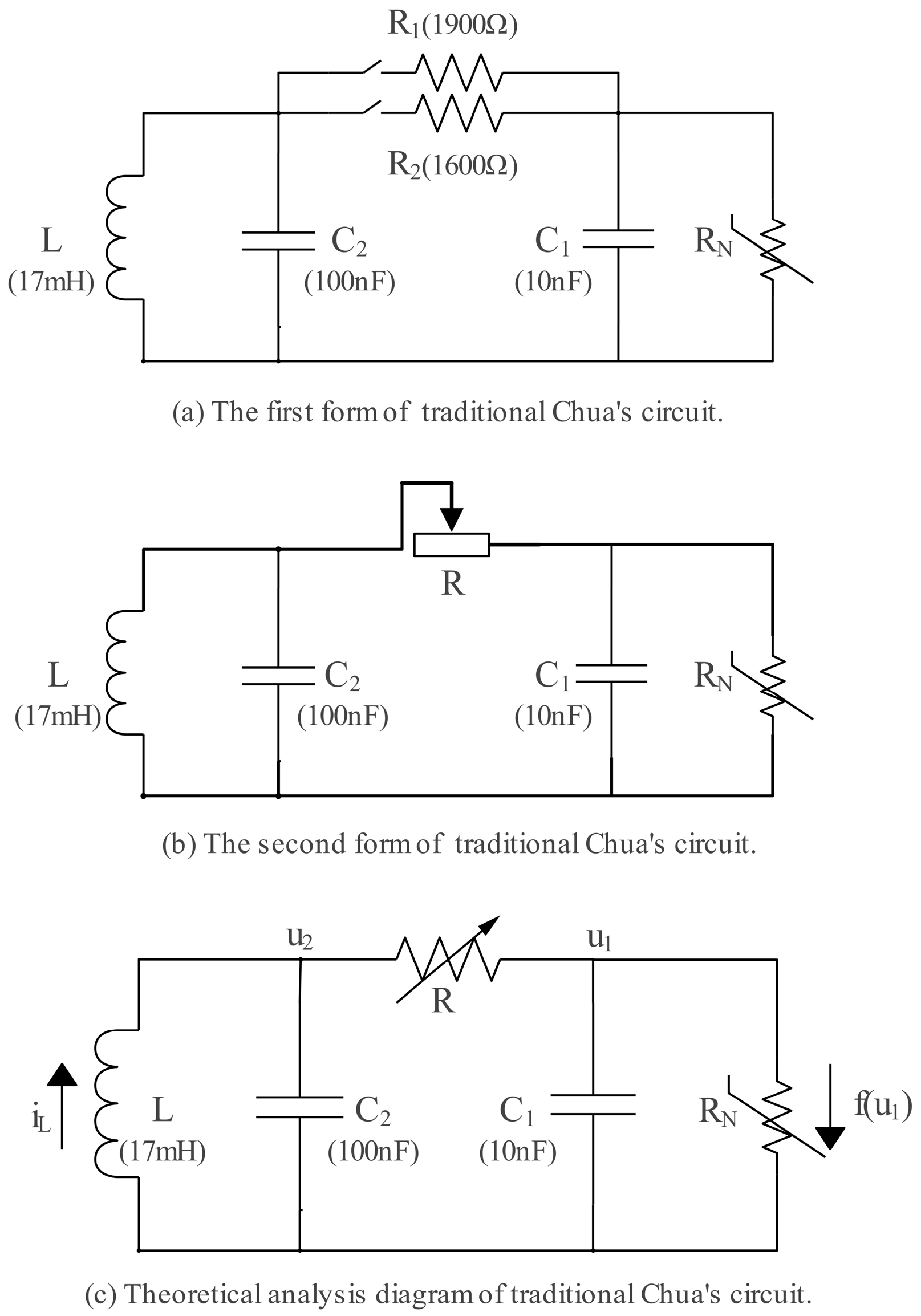
Figure 1. Traditional Chua’s circuit.
Electronics 13 02637 g001
Figure 2. Chua’s diode R N .
Electronics 13 02637 g002
Figure 3. Improved implementation of Chua’s circuit on an active inductor and non-autonomous system.
Electronics 13 02637 g003
Figure 4. Range of the adjustable parameter for different values of the extension resistor r.
Electronics 13 02637 g004
Figure 5. Average maximum error tolerance X of components L, C 1 , and C 2 for different amplitudes and frequencies.
Electronics 13 02637 g005
Figure 6. Riordan gyrator.
Electronics 13 02637 g006
Figure 7. Maximum Lyapunov exponent in the system for different resistors R.
Electronics 13 02637 g007
Figure 8. External test circuit.
Electronics 13 02637 g008
Figure 9. Average maximum error tolerance X of components L, C 1 , and C 2 for different adjustable resistors R.
Electronics 13 02637 g009
Figure 10. Average maximum error tolerance X of components L, C 1 , and C 2 for different adjustable resistors R.
Electronics 13 02637 g010
Table 1. Chaotic signals under different types of excitation current sources.
Single VortexDouble Vortex
Sine WaveElectronics 13 02637 i001Electronics 13 02637 i002
Square WaveElectronics 13 02637 i003Electronics 13 02637 i004
Triangular WaveElectronics 13 02637 i005Electronics 13 02637 i006
Table 2. The maximum Lyapunov exponent of the circuit under different parameter errors (single vortex).
min { λ o l d ( + 5 % ) , λ o l d ( 5 % ) } min { λ n e w ( + 5 % ) , λ n e w ( 5 % ) }
No Error0.410.57
L   ±   5 % −0.730.10
C 1   ±   5 % −0.850.04
C 2   ±   5 % −0.420.35
Table 3. The maximum Lyapunov exponent of the circuit under different parameter errors (double vortex).
min { λ o l d ( + 5 % ) , λ o l d ( 5 % ) } min { λ n e w ( + 5 % ) , λ n e w ( 5 % ) }
No error0.660.68
L   ±   5 % 0.030.38
C 1   ±   5 % −0.230.10
C 2   ±   5 % 0.180.49
Table 4. The maximum error tolerance Y of components L, C 1 , and C 2 , respectively (single vortex, R = 1890   Ω ).
Traditional
Chua’s Circuit
Improved Implementation
of Chua’s Circuit
L1.22%3.91%
C 1 0.76%1.80%
C 2 3.00%6.25%
Average (X)1.66%3.99%
Table 5. Signals when there is a 5% error in components L, C 1 , and C 2 , respectively (single vortex, R = 1890   Ω ).
Traditional
Chua’s Circuit
Improved Implementation
of Chua’s Circuit
L + 5 % Electronics 13 02637 i007Electronics 13 02637 i008
5 % Electronics 13 02637 i009Electronics 13 02637 i010
C 1 + 5 % Electronics 13 02637 i011Electronics 13 02637 i012
5 % Electronics 13 02637 i013Electronics 13 02637 i014
C 2 + 5 % Electronics 13 02637 i015Electronics 13 02637 i016
5 % Electronics 13 02637 i017Electronics 13 02637 i018
Table 6. The maximum error tolerance Y of components L, C 1 , and C 2 , respectively (single vortex, R = 1900   Ω ).
Traditional
Chua’s Circuit
Improved Implementation
of Chua’s Circuit
L1.76%6.97%
C 1 1.12%5.27%
C 2 2.75%9.90%
Average (X)1.88%7.38%
Table 7. Signals when there is a 5% error in components L, C 1 , and C 2 , respectively (single vortex, R = 1900   Ω ).
Traditional
Chua’s Circuit
Improved Implementation
of Chua’s Circuit
L + 5 % Electronics 13 02637 i019Electronics 13 02637 i020
5 % Electronics 13 02637 i021Electronics 13 02637 i022
C 1 + 5 % Electronics 13 02637 i023Electronics 13 02637 i024
5 % Electronics 13 02637 i025Electronics 13 02637 i026
C 2 + 5 % Electronics 13 02637 i027Electronics 13 02637 i028
5 % Electronics 13 02637 i029Electronics 13 02637 i030
Table 8. The maximum error tolerance Y of components L, C 1 , and C 2 , respectively (single vortex, R = 1910   Ω ).
Traditional
Chua’s Circuit
Improved Implementation
of Chua’s Circuit
L0.72%2.12%
C 1 0.28%0.63%
C 2 2.41%5.25%
Average (X)1.14%2.67%
Table 9. Signals when there is a 5% error in components L, C 1 , and C 2 , respectively (single vortex, R = 1910   Ω ).
Traditional
Chua’s Circuit
Improved Implementation
of Chua’s Circuit
L + 5 % Electronics 13 02637 i031Electronics 13 02637 i032
5 % Electronics 13 02637 i033Electronics 13 02637 i034
C 1 + 5 % Electronics 13 02637 i035Electronics 13 02637 i036
5 % Electronics 13 02637 i037Electronics 13 02637 i038
C 2 + 5 % Electronics 13 02637 i039Electronics 13 02637 i040
5 % Electronics 13 02637 i041Electronics 13 02637 i042
Table 10. The maximum error tolerance Y of components L, C 1 , and C 2 , respectively (double vortex, R = 1600   Ω ).
Traditional
Chua’s Circuit
Improved Implementation
of Chua’s Circuit
L5.88%10.82%
C 1 2.60%5.69%
C 2 5.72%21.31%
Average (X)4.73%12.61%
Table 11. Signals when there is a 5% error in components L, C 1 , and C 2 , respectively (double vortex, R = 1600   Ω ).
Traditional
Chua’s Circuit
Improved Implementation
of Chua’s Circuit
L + 5 % Electronics 13 02637 i043Electronics 13 02637 i044
5 % Electronics 13 02637 i045Electronics 13 02637 i046
C 1 + 5 % Electronics 13 02637 i047Electronics 13 02637 i048
5 % Electronics 13 02637 i049Electronics 13 02637 i050
C 2 + 5 % Electronics 13 02637 i051Electronics 13 02637 i052
5 % Electronics 13 02637 i053Electronics 13 02637 i054
Table 12. The maximum error tolerance Y of components L, C 1 , and C 2 , respectively (double vortex, R = 1700   Ω ).
Traditional
Chua’s Circuit
Improved Implementation
of Chua’s Circuit
L7.72%17.49%
C 1 6.24%12.03%
C 2 7.31%26.90%
Average (X)7.09%18.81%
Table 13. Signals when there is a 5% error in components L, C 1 , and C 2 , respectively (double vortex, R = 1700   Ω ).
Traditional
Chua’s Circuit
Improved Implementation
of Chua’s Circuit
L + 5 % Electronics 13 02637 i055Electronics 13 02637 i056
5 % Electronics 13 02637 i057Electronics 13 02637 i058
C 1 + 5 % Electronics 13 02637 i059Electronics 13 02637 i060
5 % Electronics 13 02637 i061Electronics 13 02637 i062
C 2 + 5 % Electronics 13 02637 i063Electronics 13 02637 i064
5 % Electronics 13 02637 i065Electronics 13 02637 i066
Table 14. The maximum error tolerance Y of components L, C 1 , and C 2 , respectively (double vortex, R = 1800   Ω ).
Traditional
Chua’s Circuit
Improved Implementation
of Chua’s Circuit
L5.37%11.04%
C 1 3.58%8.55%
C 2 6.92%15.38%
Average (X)5.29%11.66%
Table 15. Signals when there is a 5% error in components L, C 1 , and C 2 , respectively (double vortex, R = 1800   Ω ).
Traditional
Chua’s Circuit
Improved Implementation
of Chua’s Circuit
L + 5 % Electronics 13 02637 i067Electronics 13 02637 i068
5 % Electronics 13 02637 i069Electronics 13 02637 i070
C 1 + 5 % Electronics 13 02637 i071Electronics 13 02637 i072
5 % Electronics 13 02637 i073Electronics 13 02637 i074
C 2 + 5 % Electronics 13 02637 i075Electronics 13 02637 i076
5 % Electronics 13 02637 i077Electronics 13 02637 i078
Table 16. Critical points of traditional Chua’s circuit and improved implementation of Chua’s circuit.
Traditional
Chua’s Circuit
Improved Implementation
of Chua’s Circuit
Point 11989 Ω2103 Ω
Periodic Motion Electronics 13 02637 i079Electronics 13 02637 i080
Multiply Periodic MotionElectronics 13 02637 i081Electronics 13 02637 i082
Point 21910 Ω1939 Ω
Single VortexElectronics 13 02637 i083Electronics 13 02637 i084
Point 31886 Ω1868 Ω
Double VortexElectronics 13 02637 i085Electronics 13 02637 i086
Point 41575 Ω1442 Ω
Table 17. Settings for the above images.
(1)(2)(3)(4)(5)(6)(7)(8)
Time Base (ms)5050505050505050
Gradation of Channel A (V/Div)1111110.50.5
Gradation of Channel B (V/Div)52525222
Disclaimer/Publisher’s Note: The statements, opinions and data contained in all publications are solely those of the individual author(s) and contributor(s) and not of MDPI and/or the editor(s). MDPI and/or the editor(s) disclaim responsibility for any injury to people or property resulting from any ideas, methods, instructions or products referred to in the content.