1. Introduction
More than 2.5 billion people in the world will suffer from hearing loss by 2050 [
1]. Hearing loss is prevalent in the elderly population. For example, the prevalence of hearing loss among people aged 71–80 in the UK is about 42% for men and 39% for women. Nevertheless, it increases sharply after age 80, and hearing impairment is a significant cause of dementia [
2,
3,
4]. Therefore, it is necessary to solve the hearing-loss problem immediately after diagnosis. Several measures are now available for rehabilitating people with hearing loss, including the use of analog, programmable analog, and digital hearing aids. Analog hearing aids are the mainstay of hearing rehabilitation. They are cost-effective and readily available in most hearing departments [
5]. However, analog hearing aids also have limitations. They can only amplify sound and cannot distinguish between environmental noise and the actual human voice that needs amplification. LoCHAid is a fixed-frequency hearing aid that has the advantage of being low-cost [
6], but due to its fixed frequency, it cannot be adjusted for individual hearing improvement needs. The Oticon Spirit Zest hearing aid effectively addresses this issue but struggles to amplify the desired sounds in noisy environments and requires adjustments by professional audiologists. The project proposed in this paper can effectively solve the problems of the aforementioned devices. It utilizes deep learning to amplify target sounds in noisy environments and provides excellent hearing adaptation for individuals with different hearing needs.
The hearing aid is designed to be a device with low power consumption and minimal complexity. While Audio-Encoder (AE)-based Sound-Stream presents a promising approach, the requirement for neural networks at both the transmitting and receiving ends renders it impractical for our hearing-aid context. As a solution, we suggest delegating the bulk of audio codec processing to the cloud, which can leverage high-performance GPUs for expedited processing, therefore diminishing latency. A multimodal hearing aid utilizes 5G technology to achieve more efficient data transmission and processing capabilities by integrating both visual and auditory modalities and transmitting the data to the cloud. Using machine-learning methods, it provides more accurate noise filtering and sound enhancement in noisy environments. Furthermore, leveraging the high-bandwidth and low-latency characteristics of 5G networks, our hearing-aid prototype can achieve real-time data processing, providing instant sound enhancement and noise-reduction effects.
It necessitates a transmitter of low complexity for the uplink (transmitting audio to the cloud) and equally a receiver of high data rate and low complexity for the downlink (receiving audio at the hearing aid) [
7]. A new solution is proposed for modern hearing aid devices, as illustrated in
Figure 1. At the TX end, audio and image data from the environment are received via a microphone and camera, respectively. These data are transmitted through an FPGA board to the cloud for processing. Once processed, enhanced speech is transmitted back from the RX end to the FPGA platform, and then noise-reduced audio is transmitted via the microphone [
8]. The project described in this paper focuses on the TX part of this solution, which involves the rapid transmission of low-data streams to the cloud. The logic design of TX utilizes the hardware description language Verilog and is implemented in the VIVADO 2022.2 version. This paper focuses solely on the implementation process of the TX end, validating the feasibility of its implementation on the RFSOC4*2 AMD FPGA platform. The RFSOC4*2 AMD FPGA integrates RF data converters capable of directly processing high-frequency signals, making it more suitable for high-performance, low-latency applications such as wireless communication, radar systems and software-defined radio. Therefore, the processor and high-performance data conversion capabilities integrated into the RFSOC4*2 AMD FPGA provide significant advantages in demanding application scenarios. MATLAB R2022a simulation results are compared with VIVADO results to demonstrate the accuracy of the findings. The MATLAB code outputs compared in this paper are based on the results presented in paper [
9]. Having verified the accuracy of the MATLAB code results from the referenced article, this paper contrasts its generated outputs with those from the article. This comparison allows for an assessment of the module’s accuracy and latency.
The paper is organized as follows:
Section 1 describes the current status and background of low-power wearable devices (hearing aids) and FPGA. This section also outlines the general objectives of the project. In the second section, the architecture design will be described. In this section, the principles and objectives of each step are elaborated, as well as the Cloud-based Audio-Visual Codec [
9] algorithm has been optimized for better compatibility with FPGA logic, enhancing system efficiency. In
Section 3, the simulation results section comparing the simulation results will start with the individual modules, and then the whole project will be evaluated to verify its effectiveness. Finally, this study validates the process of analog transmission simulation of the Cloud Hearing Aid on an FPGA platform and illustrates the potential of this device to improve the hearing assistance aspect.
2. Architecture Design of Cloud Hearing Aid Module
The subsequent stages involve outlining the modular design of the project and dividing the entire project into three major modules. As shown in
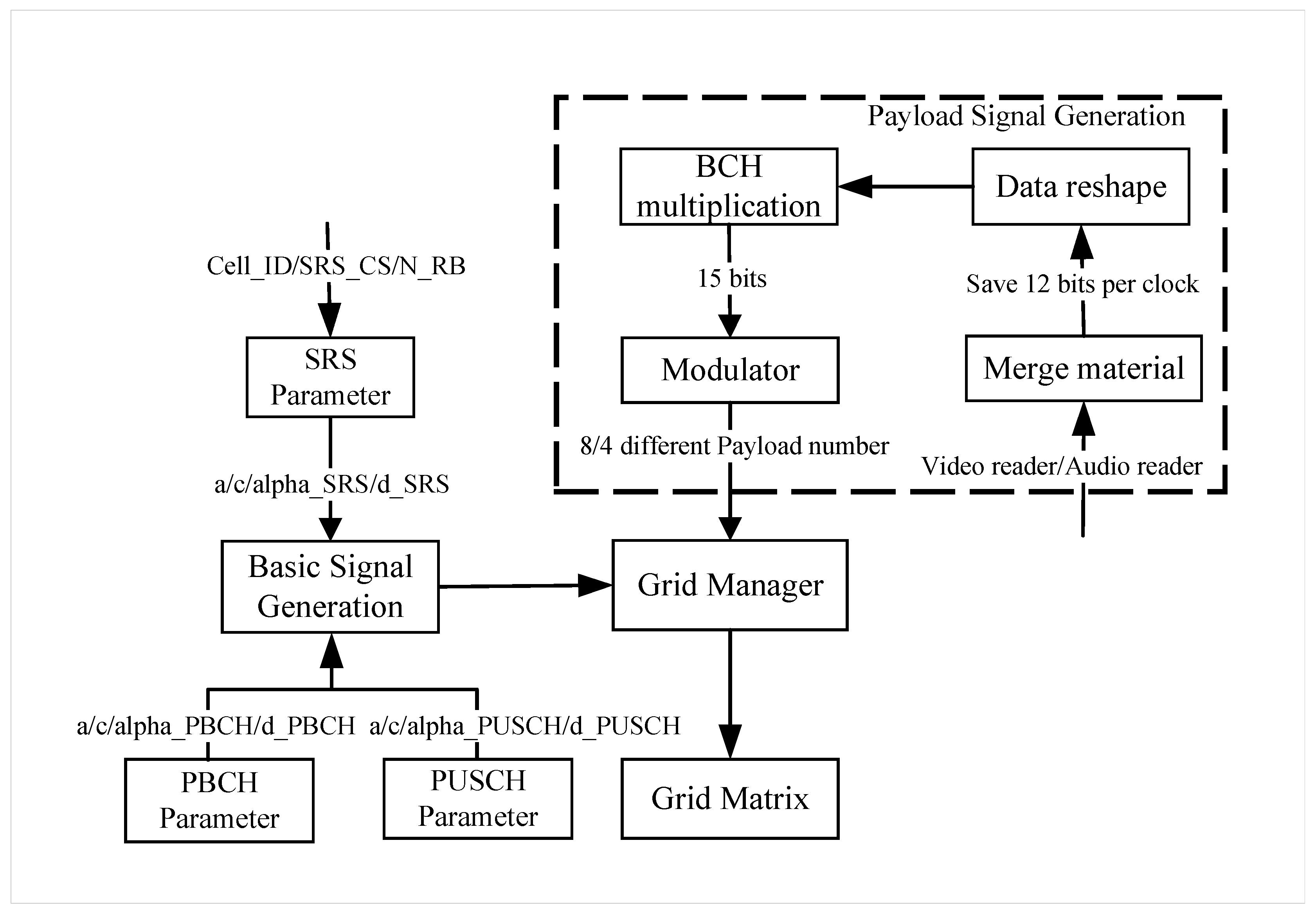
Figure 2, the complete project includes three sets of address and complex number connections: the “Basic Signal Generation”, “Payload Signal Generation”, “Grid Manager”.
As shown in
Table 1, the N_RB value determines the matrix row, while the column remains constant at 140. The Verilog program computes the reference SRS, a part of DMRS-PBCH (Physical Broadcast Channel, PBCH Part 1), and the complete DMRS-PUSCH (Physical Uplink Shared Channel) signals. It processes video and audio bits as payload, generating the remaining DMRS-PBCH signals (PBCH Part 2). This circular process repeats until the full TX (Transmitter) signal is generated, which is also the arrangement order within the grid matrix. As shown in Algorithm 1, the pseudocode clearly describes the sequence of signal generation.
| Algorithm 1: State Machine |
![Electronics 13 02588 i001]() |
2.1. Basic Signal Generation
In the design of multimodal hearing aids, Orthogonal Frequency Division Multiplexing (OFDM) technology significantly improves bandwidth efficiency and reduces interference. OFDM enhances spectrum utilization through multi-carrier transmission and efficient spectral use, enabling the transmission of more data within a limited bandwidth. Additionally, OFDM adaptive modulation adjusts the modulation scheme of each subcarrier based on channel conditions, optimizing bandwidth utilization. Finally, dynamic spectrum allocation allows OFDM to avoid interfered or occupied frequency bands, reducing the impact of external interference [
10]. Through these technologies, OFDM provides efficient and reliable signal transmission in wireless communication, significantly enhancing the performance of hearing aids and the user experience.
The OFDM reference signal comprises SRS, DMRS-PBCH, and DMRS-PUSCH signals, each carrying vital encoded data. In the design of multimodal hearing aids, the SRS, DMRS, PBCH, and PUSCH modules each play a critical role. The SRS module measures channel state through sounding reference signals, helping devices optimize transmission parameters and ensure stable, high-quality communication. The PBCH module transmits system information and network configuration parameters, ensuring the hearing aid correctly connects to and configures network resources. The PUSCH module is used to upload user data and channel state information, enabling efficient data transmission and real-time interaction. These modules work together to ensure that the hearing aid provides efficient, stable, and high-quality auditory enhancement services in complex environments [
11].
This section focuses on the calculation of essential parameters for the SRS, PUSCH, and PBCH modules. The method used for calculating the parameters is according to the 3GPP TS 38.211 technical specification document [
12]. Notably, according to the technical specification document, calculating the basic parameters of the module requires 20 formulas, many of which share common terms that can be consolidated into five parameters (
alpha,
a,
b,
c, and
d) for parameter generation. In Formula (1), Formula a corresponds to the SRS formula, and Formula b is used for the generation of PUSCH and PBCH. In Formula (4), the value of the
Z variable when generating SRS, PBCH, and PUSCH is, respectively,
SRS_CS, 2, 1, where
N_RB,
SRS_CS, and
cell_ID in the formulas are defined parameters, as demonstrated in Equations (1)–(6):
Figure 2 shows the variable input and output plot of the basic parameter generator. Parameters
a and
c are shared among the SRS_Parameter, PBCH_Parameter, and PUSCH_Parameter modules. This module block first calculates the phase value, sends it to the trigonometric module to obtain the complex form of the slot value, and then saves it into the grid matrix.
The analysis of Formula (6) shows that they produce reference signals through the same mathematical expressions. Given this conversion of all OFDM reference signals into exponential formats, implementing their direct computation in Verilog poses significant challenges. The transformation from exponential functions to trigonometric functions based on Euler’s Formula (7) can be efficiently computed using trigonometric calculations [
13], resulting in a complex output that can be stored in the grid matrix. In VIVADO, the transition to trigonometric computations can be efficiently facilitated using the “DDS Compiler” IP core (Direct Digital Synthesizers), the DDS Compiler features a SIN/COS Look-Up Table (LUT) module that can execute various mathematical functions. This component is designed to deliver trigonometric outcomes by referencing a built-in table that contains a wide array of precalculated values. Inputs in the form of phase values, ranging from
to
(in radians), are processed by the sine/cosine LUT, which then generates output values within the −1 to 1 spectrum. These outputs are evenly spaced across the entirety of the output’s bit range. For this purpose, Euler’s formula should be used, and Formula (6) should be simplified, as shown in Formula (8). By omitting the
term, the calculation process is significantly simplified, resulting in both lower resource consumption and decreased latency in data transmission.
2.2. Payload Signal Generation
Within the payload signal-generation section, as outlined in
Figure 2, the process incorporates a Data-Reshape module, a BCH driver module, and a Modulator module.
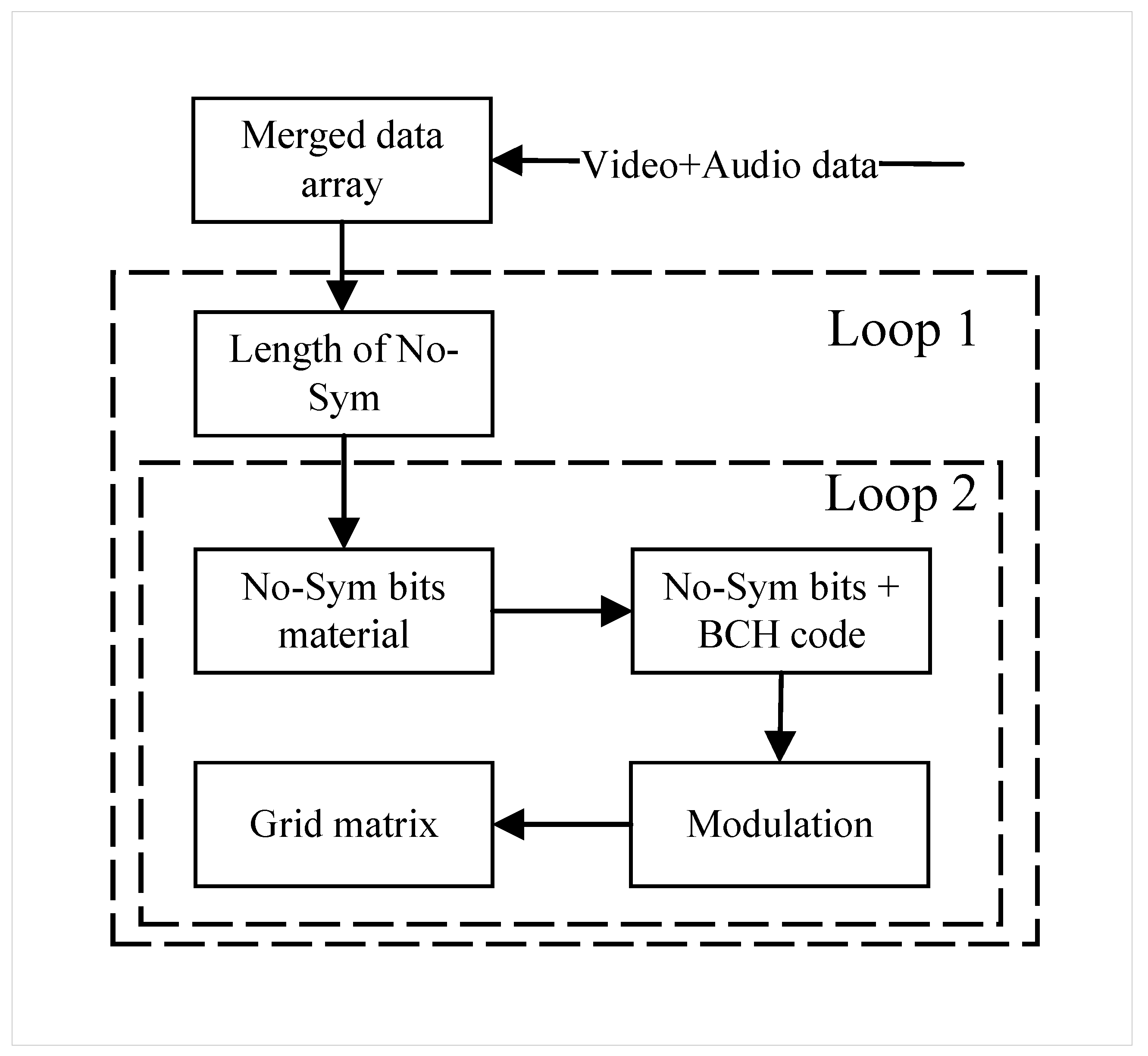
Figure 3 illustrates the main steps involved in generating payload signals. Bit number N depends on the inputted code rate, and the choice of modulation type (whether QPSK or 16-QAM) is based on the value of MOD(Modulation scheme), encodes various bits of data using different BCH primitive polynomials, and modulates the encoded data with QPSK or 16-QAM, depending on the required modulation type for the project. The entire payload number is generated within 2 loops. Loop 1 operates on the No-SYM bit signal one at a time until all signal material is filled. Loop 2 is contained within Loop 1. It encodes and modulates the received No-SYM bit signals and fills the payload slots in the grid matrix with these modulated complexes. When Loop 2 completes a cycle, all the payload slots in the grid matrix can be filled. Therefore, each time Loop 1 is repeated, the grid matrix is refilled.
Once all complex values related to the payload have been generated, a completion signal is forwarded to the PBCH Part 2 module. The outputs of the Payload Signal Generation and the Basic Signals Generation are sequentially combined and dispatched to the Grid Manager for transmission.
2.2.1. Material Merging Method
The Merge Material Module, depicted in
Figure 4, is designed to combine video and audio data by first retrieving 8 bits of video from a file, followed by 4 bits of audio, and repeating this sequence until all video bits are incorporated into the array. If the video data consists of
M bits, this process will be repeated (
M/8) times, leading to a total merged length of (
3M/2) bits.
The choice to use 8-bit for video and 4-bit for audio transmissions is based on several considerations: 8-bit video supports a wide color range, offers good compatibility, and simplifies processing workflows, making it suitable for most video applications. In contrast, 4-bit audio, while ensuring basic sound quality, significantly enhances storage and transmission efficiency, optimizes overall system performance and cost-effectiveness, and is especially beneficial in resource-limited environments [
14]. These decisions reflect a balanced consideration of performance, cost, and efficiency across hearing-aid application scenarios.
As shown in
Figure 5, the grid matrix requires the original merged material to be divided into N columns to be filled into the grid matrix. However, the merged material cannot always be evenly divided. In many cases, there is a shortage of the original merged material in the last cycle, possibly missing some bits. The missing bits are not simply filled with all zeros. Instead, they are divided into four parts, alternately filled with 1 s and 0 s. This padding strategy not only meets the length requirements but also helps maintain the integrity of the signal, prevents misoperations, and improves decoding efficiency.
2.2.2. BCH and Modulation Method
To ensure data integrity and reliability, it is essential to implement secure encoding and error correction mechanisms. The BCH (Broadcast Channel) code, a variant of cyclic code utilized for error correction, functions by conducting a multiplication of the original message polynomials with primitive polynomials in the Galois field [
15]. This approach enables the receiver end of the coding process to validate the integrity of the transmitted message and accurately identify the location of one or more erroneous bits.
Illustrated in
Figure 6, the BCH driver module consists of two main sections—the Data-Reshape module and the BCH multiplication module—which reshape merge material for BCH input and then encode it. It directs the reshaped bits to the BCH multiplication module. The Data-Reshape module adjusts its processing based on the initial code rate values of the payload module, which are 0.46 and 0.73, corresponding to input data bits of 7 bits and 11 bits, respectively. Therefore, in the corresponding BCH multiplier module, it is necessary to generate 8 bits and 4 bits of BCH bits. The BCH multiplier, essential in the GF(2) field and detailed in Formula (9) [
16], performs multiplication operations where
s(
x) is the result,
g(
x) is the original information polynomial, and
p(
x) is the primitive polynomial. Given the requirements to generate BCH code bits of 8 and 4 bits,
p(
x) varies and corresponds to scenarios (
a) and (
b), respectively, as defined in Formula (10). It multiplies the incoming information bits by the primitive polynomial, generating a 15-bit result for the target BCH module.
The utilization of modulation enhances the system’s resistance to noise and interference, therefore increasing the security and privacy of communication [
17]. This project employs QPSK (Quadrature Phase Shift Key) or 16-QAM (Quadrature Amplitude Modulation) to encode computed results, offering four unique signal states and 16 unique signal states, respectively [
18]. In
Figure 6, observe the structure of the modulation section following the BCH driver module. Initially, it performs modulation using either QPSK or 16-QAM. With QPSK, it produces one complex number for every 2 bits, while 16-QAM yields a complex number for every 4 input bits. Consequently, the modulation module can generate 8 complex numbers in a single clock cycle if QPSK is used or 4 complex numbers if 16-QAM is employed. This implies that parallel generation necessitates 8 QPSK modules or 4 16-QAM modules.
3. Results and Discussion
The project recorded images and audio in a real environment, transmitting a total of 74 lip images with a total size of 156 KB, along with a 3-second test audio clip with a size of 94 KB. This section initially introduces the verification algorithm, elucidates the rationale behind its selection, and showcases the simulated signal it generates. This segment includes a significant array of figures to exhibit the outcomes. In this simulation part, the input bandwidth, cell_ID, modulation method, code rate, and SRS_CS used in the result simulation are 1.4 MHZ, 54, QPSK, 0.73, and 3, respectively. In this project, all outputs are binary with one sign bit, four integer bits, and a decimal part, which is converted to its original binary representation and then to its decimal equivalent.
3.1. Simualtion Result of Basic Signal Generation
The phase and address generator employs a Finite State Machine (FSM) to produce phases and addresses for all three types of basic signals. Following this initialization, the generator proceeds to generate the basic signals, namely SRS, PBCH Part 1, and PUSCH, during states 1, 2, and 3, as depicted in
Figure 7. The time taken to generate the basic signal is 328.745 ms. Since the precision of the project is set to 0.0001, this will result in essentially the same value for both Verilog and MATLAB simulations, which can be considered acceptable noise.
We export the simulation results from VIVADO to MATLAB for processing and compare the results obtained from the first ten points in the VIVADO simulation data with the results in MATLAB. The results are described below:
As shown in
Figure 8a, the SRS addresses is within the range of the first column of
Table 1, the first ten bits, from bit 0 to bit 108, are compared, taking approximately 1.075
s to generate the SRS. As shown in
Figure 8b, the first part of PBCH addresses falls within the range of the second column of
Table 1, the first ten bits, from bit 108 to bit 215, are compared, taking approximately 0.27
s to calculate the first part of the PBCH value. s to generate. As shown in
Figure 8c, PUSCH addresses are within the range of the third column of
Table 1, the first ten bits, from bit 216 to 323, are compared, taking 24.84
s to generate PUSCH values. As shown in
Figure 8d, in contrast to the first part of PBCH, the second part of the PBCH module mainly focuses on MIB generation, encoding, and modulation tasks. Specifically, for numerical comparison, we selected these complex numbers because, under the selected global input parameters, these complex numbers remain consistent among various output complex numbers.
3.2. Simualtion Result of Payload Signal Generation
Figure 9 displays the RTL diagram of the Payload module. In this diagram, the input modules for audio and video, named Read_audio and Read_video, respectively, transmit data to the Merging_manager. The data then undergoes processing by the BCH_driver module and the QAMMOD_driver module before the final output is generated. The data from the BCH module and the QAMMOD module are displayed separately.
The BCH driver module consists of two main sections: the Data-Reshape module and the BCH multiplication module. Given that the code rate of the test data is 0.73, the Data-Reshape module outputs 11-bit input bits, and the BCH multiplication module outputs 4-bit BCH code bits, which are then combined to generate a 15-bit signal output.
Table 2 and
Figure 10 illustrate an example of 11-bit reshaping in the Data-Reshape module, comparing the operation between MATLAB and the RTL implementation. The BCH encoder extensively employs XOR logic gates and utilizes distinct primitive polynomials as well as combined polynomials.
Table 2 and
Figure 11 compare the first 3 encoded outputs of the 15-bit BCH multiplication module. The Verilog outputs are correct.
The results of the QAMMOD (modulator) module are illustrated in
Figure 12. These modulation modules are entirely responsible for determining the required complex numbers based on the input bits. The VIVADO payload module directly provides 36-bit complex numbers, where the initial 18 bits represent the real part, followed by 18 bits representing the imaginary part. Importing the results into MATLAB for processing maintains consistency between MATLAB and VIVADO results.
3.3. Entire Module Simulation
The grid module saves signals from three modules in a sequence, starting with the basic signal generation, followed by the payload module. This sequence persists until the PUSCH module receives the EoD signal, which means the transmission is complete, as shown in
Figure 13.
Figure 14 describes the method of combining the Basic_signal, Payload_signal, and PBCH Part2 signals. Achieving a transmission time of only 4.789 ms has a significantly positive impact on the user experience of hearing aids. This extremely low latency ensures that sound signals are transmitted and processed almost in real time, so users do not perceive any delay when hearing sounds. This ensures the natural synchronization of conversations and ambient sounds.
As shown in
Table 3, the transmission latency of this study is compared with that of advanced codecs. The Enhanced Voice Services (EVS) codec is the latest standardized codec by 3GPP, primarily designed for LTE voice (VoLTE) communications [
19]. Opus, referenced as [
20], is a versatile voice and audio codec that has been widely adopted for voice communication over the Internet since its standardization by the IETF in 2012, including applications like YouTube, Skype, and others. The Sound-Stream codec, utilized by Google [
21], has shown improvement in low-bitrate data transmission, but its 26 ms latency still falls short of the target latency of within 10 ms. The transmission end successfully transmitted a low-bit-rate image file of lips, size 156 KB, and a voice file of 94 KB, completing the transfer in 4.789 ms. Under the same file conditions, reference [
9] reports that the transmission completed using MATLAB on a CPU took 47.93 ms. This is attributed to the unique hardware architecture design presented in this paper and the parallel transmission rates achievable with FPGA. The originality of the proposed 5G OFDM algorithm is highlighted by the following features. FPGA possesses powerful parallel-processing capabilities, enabling it to handle multiple tasks simultaneously. This makes it exceptionally suitable for implementing the parallel computation characteristics of OFDM, therefore significantly enhancing processing speed and efficiency. The OFDM algorithm can be implemented in a way that minimizes the use of FPGA resources (such as logic units and memory blocks), which is crucial for maintaining high performance while reducing hardware costs.
The resource utilization of the aforementioned modules was validated in an RFSoC AMD FPGA, with the results of the resource occupation listed in
Table 4. The project consumed only 1% of the various available resources in the FPGA. In
Table 5, a comparison of hardware resources between the transmitters designed in references [
21,
22,
23,
24,
25,
26,
27] and the project designed in this paper is presented. The comparison reveals that, compared to the project, this paper demonstrates significantly lower resource utilization in terms of RAM, flip-flops, and clock buffers. As shown in
Figure 15, the results of the implementation for this project are presented. The derived results correspond to the synthesis results, with a total on-chip power consumption of 1.332 W.
4. Conclusions and Future Work
In conclusion, with the rapid development of the telecommunications industry, multimodal hearing aids need to improve the quality of service for data/image transmission. How to transmit data quickly at a low bit rate has always been a focal point of research. This paper presents a design for a multimodal hearing-aid transmitter that has been optimized by refining the algorithms of the Cloud-based Audio-Visual Codec [
9], making it more suitable for the unique pipeline and parallel-processing methods of FPGA. The design modularly separates functionality into several algorithmic components: the Sound Reference Signal (SRS), which calibrates and synchronizes the audio inputs; the Demodulation Reference Signal (DMRS) to maintain integrity and accuracy in signal demodulation; the Physical Broadcast Channel (PBCH), which handles the broadcasting of system information; and the Physical Uplink Shared Channel (PUSCH), dedicated to transmitting user data effectively.
The grid matrix effectively stores all generated basic valid payload signals, accurately simulating the data values and slot orders modeled in MATLAB code and successfully porting the audio–video codec to the RFSoC AMD FPGA platform. Notably, the transmission part of the program is completed in just 4.789 ms. Compared to the industry standard EVS codec, Opus codec, and Sound-Stream codec, it performs excellently in the low-bitrate transmission of video and audio. Furthermore, compared to Project 21, it uses the least hardware resources, fully demonstrating high efficiency and powerful scalability. A transmission speed of 4.789 ms surpasses most commercial analog hearing aids. This speed not only enhances the user experience but also creates conditions for real-time processing and exceptional audio quality. The proposed algorithm is fully capable of being developed and implemented in future products. Currently, only the transmitter (TX) side has been completed. In future work, the focus will be on completing the receiver (RX) side, which will include the entire workflow of data transmission and reception. Ultimately, this system can be integrated into multimodal hearing aids while maintaining a reasonable budget of resource and power consumption, thus completing the transmission part of next-generation multimodal hearing aids. The algorithm designed in this paper not only reduces hardware resources and power consumption but also achieves secure and fast audio and video transmission. This provides a solid foundation for data transmission in multimodal hearing aids. It extends the daily usage time of hearing-aid devices and enhances instant communication and social interaction through fast data transmission, therefore improving the practicality and efficiency of multimodal hearing aids. In the future, cloud-based machine-learning noise-reduction methods can meet users’ needs in noisy environments, making multimodal hearing aids more attractive in the market.
Author Contributions
Conceptualization, X.N. and T.A.; data curation, X.N.; formal analysis, X.N. and Y.C.; funding acquisition, T.A.; investigation, X.N.; methodology, X.N. and T.A.; project administration, T.A.; resources, T.A.; software, X.N. and Y.C.; supervision, T.A.; validation, X.N. and T.A.; visualization, X.N. and T.A.; writing—original draft, X.N.; writing—review and editing, X.N., G.E., T.T. and T.A. All authors have read and agreed to the published version of the manuscript.
Funding
Tughrul Arslan has funding from the U.K. Engineering and Physical Sciences Research Council (EPSRC) programme grant: COG-MHEAR, under grant EP/T021063/1.
Institutional Review Board Statement
Not applicable.
Informed Consent Statement
Not applicable.
Data Availability Statement
Data is contained within the article.
Acknowledgments
This work was supported by the COG-MHEAR research program and the UK Engineering and Physical Sciences Research Council (EPSRC) under grant number EP/T021063/1. The author thank Yang Cen and Tushar Tyagi for their support during the project, and Tushar Tyagi, Godwin Enemali, and Tughrul Arslan for their support in improving the paper.
Conflicts of Interest
The authors declare no conflicts of interest.
Abbreviations
The following abbreviations are used in this manuscript:
| HA | Hearing Aid |
| FPGA | Field programmable gate array |
| NR | New Radio |
| OFDM | Orthogonal Frequency Division Multiplexing |
| IoT | Internet of Things |
| SRS | Sound reference signal |
| DMRS | Demodulation Reference Signal |
| PBCH | Physical Broadcast Channel |
| PUSCH | Physical Uplink Shared Channel |
| BCH | Broadcast Channel |
| QPSK | Quadrature Phase Shift Key |
| 16-QAM | Quadrature Amplitude Modulation |
| FSM | Finite State Machine |
| EVS | Enhanced Voice Services |
| LUT | Look-Up Table RAM |
| FF | Flip-Flop |
| IO | input/Output |
| BUFG | Time Buffer |
| MOD | Modulation scheme |
References
- World Health Organization. Ireland and WHO Work Together to Improve Access to Assistive Technology Globally; World Health Organization: Geneva, Switzerland, 2024. [Google Scholar]
- Anwar, U.; Arslan, T.; Hussain, A. Hearing Loss, Cognitive Load and Dementia: An Overview of Interrelation, Detection and Monitoring Challenges with Wearable Non-invasive Microwave Sensors. arXiv 2022, arXiv:2202.03973. [Google Scholar]
- Ray, M.; Dening, T.; Crosbie, B. Dementia and hearing loss: A narrative review. Maturitas 2019, 128, 64–69. [Google Scholar] [CrossRef] [PubMed]
- Lesica, N.A. Why do hearing aids fail to restore normal auditory perception? Trends Neurosci. 2018, 41, 174–185. [Google Scholar] [CrossRef] [PubMed]
- Béjar-Solar, I.; Rosete, M.; De Jesus Madrazo, M.; Baltierra, C. Percutaneous bone-anchored hearing aids at a pediatric institution. Otolaryngol. Neck Surg. 2000, 122, 887–891. [Google Scholar] [CrossRef] [PubMed]
- Sinha, S.; Irani, U.D.; Manchaiah, V.; Bhamla, M.S. LoCHAid: An ultra-low-cost hearing aid for age-related hearing loss. PLoS ONE 2020, 15, e0238922. [Google Scholar] [CrossRef] [PubMed]
- Yi, S.; Chun, S.; Lee, Y.; Park, S.; Jung, S. Radio Protocols for LTE and LTE-Advanced; John Wiley & Sons: Hoboken, NJ, USA, 2012. [Google Scholar]
- Enemali, G.; Bishnu, A.; Ratnarajah, T.; Arslan, T. Towards an FPGA implementation of IOT-based multi-modal Hearing AID System. In Proceedings of the 2023 IEEE International Conference on Acoustics, Speech, and Signal Processing Workshops (ICASSPW), Rhodes Island, Greece, 4–10 June 2023; pp. 1–4. [Google Scholar]
- Bishnu, A.; Gupta, A.; Gogate, M.; Dashtipour, K.; Adeel, A.; Hussain, A.; Sellathurai, M.; Ratnarajah, T. A novel frame structure for cloud-based audio-visual speech enhancement in multimodal hearing-aids. In Proceedings of the 2022 IEEE International Conference on E-Health Networking, Application & Services (HealthCom), Genoa, Italy, 17–19 October 2022; pp. 75–80. [Google Scholar]
- Harkat, H.; Monteiro, P.; Gameiro, A.; Guiomar, F.; Farhana Thariq Ahmed, H. A survey on MIMO-OFDM systems: Review of recent trends. Signals 2022, 3, 359–395. [Google Scholar] [CrossRef]
- Chiueh, T.D.; Tsai, P.Y.; Lai, I.W. Baseband Receiver Design for Wireless MIMO-OFDM Communications; John Wiley & Sons: Hoboken, NJ, USA, 2012. [Google Scholar]
- 5G-NR. Physical Layer Procedures for Control. Technical Specification (TS) 38.213, 3rd Generation Partnership Project (3GPP); Version 15.6.0; 3GPP: Sophia Antipolis, France, 2019. [Google Scholar]
- Lunn, A.; Maths, I.H.L. Proving Euler’s Formula. 2015. Available online: https://www.academia.edu/21500294/Proving_Eulers_Formula (accessed on 1 October 2023).
- Rijkse, K. H. 263: Video coding for low-bit-rate communication. IEEE Commun. Mag. 1996, 34, 42–45. [Google Scholar] [CrossRef]
- Ding, C. Parameters of several classes of BCH codes. IEEE Trans. Inf. Theory 2015, 61, 5322–5330. [Google Scholar] [CrossRef]
- Spagnol, C.; Popovici, E.M.; Marnane, W.P. Hardware Implementation of GF(2m) LDPC Decoders. IEEE Trans. Circuits Syst. I Regul. Pap. 2009, 56, 2609–2620. [Google Scholar] [CrossRef]
- Mesleh, R.; Alhassi, A. Space Modulation Techniques; John Wiley & Sons: Hoboken, NJ, USA, 2018. [Google Scholar]
- Islam, I.; Hossain, S. Comparison of traffic performance of QPSK and 16-QAM modulation techniques for OFDM system. J. Telecommun. Inf. Technol. 2005, 1, 147–152. [Google Scholar] [CrossRef]
- Dietz, M.; Multrus, M.; Eksler, V.; Malenovsky, V.; Norvell, E.; Pobloth, H.; Miao, L.; Wang, Z.; Laaksonen, L.; Vasilache, A.; et al. Overview of the EVS codec architecture. In Proceedings of the 2015 IEEE International Conference on Acoustics, Speech and Signal Processing (ICASSP), South Brisbane, QLD, Australia, 19–24 April 2015; pp. 5698–5702. [Google Scholar] [CrossRef]
- Valin, J.M.; Vos, K.; Terriberry, T. Definition of the Opus Audio Codec. 2012. Available online: https://www.opus-codec.org/ (accessed on 16 October 2023).
- Zeghidour, N.; Luebs, A.; Omran, A.; Skoglund, J.; Tagliasacchi, M. Soundstream: An end-to-end neural audio codec. IEEE/ACM Trans. Audio Speech Lang. Process. 2021, 30, 495–507. [Google Scholar] [CrossRef]
- T R, V.K. FPGA Based Efficient OFDM Based Design and Implementation for Data and Image Transmission for Healthcare. Int. J. Recent Technol. Eng. 2023, 12, 28–33. [Google Scholar] [CrossRef]
- Chacko, J.; Sahin, C.; Nguyen, D.; Pfeil, D.; Kandasamy, N.; Dandekar, K. FPGA-based latency-insensitive OFDM pipeline for wireless research. In Proceedings of the 2014 IEEE High Performance Extreme Computing Conference (HPEC), Waltham, MA USA, 9–11 September 2014; pp. 1–6. [Google Scholar]
- Kiokes, G.; Economakos, G.; Amditis, A.; Uzunoglu, N.K. Design and implementation of an OFDM system for vehicular communications with FPGA technologies. In Proceedings of the 2011 6th International Conference on Design & Technology of Integrated Systems in Nanoscale Era (DTIS), Athens, Greece, 6–8 April 2011; pp. 1–6. [Google Scholar]
- Kaur, S.; Mehra, R. FPGA implementation of OFDM Transceiver using FFT Algorithm. Int. J. Eng. Sci. Technol. (IJEST) 2012, 4, 1532–1537. [Google Scholar]
- Garcia, J.; Cumplido, R. On the design of an FPGA-based OFDM modulator for IEEE 802.16-2004. In Proceedings of the 2005 International Conference on Reconfigurable Computing and FPGAs (ReConFig’05), Puebla City, Mexico, 28–30 September 2005; pp. 102–107. [Google Scholar]
- Desai, A.; Gupta, A.; Jambhale, M.; Chavan, V. Efficient implementation technique for OFDM on FPGA. In Proceedings of the 4th International Conference on Advances in Science & Technology (ICAST2021), Bahir Dar, Ethiopia, 27–29 August 2021. [Google Scholar]
- Ishtiaq, A.; Javed, A.; Akhtar, A.; Zulfiqar, U.B.; Nisar, M.D. Efficient implementation of OFDM waveform on Xilinx FPGA. In Proceedings of the 2017 International Symposium on Wireless Systems and Networks (ISWSN), Lahore, Pakistan, 19–22 November 2017; pp. 1–5. [Google Scholar]
Figure 1.
Overview of a loT-based Multimodal hearing aid system.
Figure 1.
Overview of a loT-based Multimodal hearing aid system.
Figure 2.
Main terminals in grid manager.
Figure 2.
Main terminals in grid manager.
Figure 3.
Main steps in payload signal generation.
Figure 3.
Main steps in payload signal generation.
Figure 4.
Merging method of Video and Audio bits.
Figure 4.
Merging method of Video and Audio bits.
Figure 5.
Grid Matrix structure.
Figure 5.
Grid Matrix structure.
Figure 6.
Payload MCH module file structure.
Figure 6.
Payload MCH module file structure.
Figure 7.
Overall basic signal-generator simulation.
Figure 7.
Overall basic signal-generator simulation.
Figure 8.
10 pieces of data of a basic signal-generator simulation signal in MATLAB and VIVADO.
Figure 8.
10 pieces of data of a basic signal-generator simulation signal in MATLAB and VIVADO.
Figure 9.
Payload module RTL diagram.
Figure 9.
Payload module RTL diagram.
Figure 10.
First 3 results of 11-bit BCH input converge in VIVADO.
Figure 10.
First 3 results of 11-bit BCH input converge in VIVADO.
Figure 11.
First 3 results of 15-bit BCH output in VIVADO.
Figure 11.
First 3 results of 15-bit BCH output in VIVADO.
Figure 12.
QPSK and 16-QAM constellation diagram in unit power.
Figure 12.
QPSK and 16-QAM constellation diagram in unit power.
Figure 13.
Overview of output grid signal.
Figure 13.
Overview of output grid signal.
Figure 14.
Temporal distribution of grid signal.
Figure 14.
Temporal distribution of grid signal.
Figure 15.
RFSOC4*2 implementation result.
Figure 15.
RFSOC4*2 implementation result.
Table 1.
Slot filling method for No-Sym single group.
Table 1.
Slot filling method for No-Sym single group.
| SRS | DMRS-PBCH + PUSCH | DMRS-PBCH_Part2 + Payload |
|---|
| Index[1] | Index[12N_RB + 1] | Index[24N_RB + 1] | ... | ... |
| Index[2] | Index[12N_RB + 2] | Index[24N_RB + 2] | ... | ... |
| ... | ... | ... | ... | ... |
| Index[12N_RB − 1] | Index[24N_RB − 1] | Index[36N_RB − 1] | ... | Index[104 × 12N_RB −1 ] |
| Index[12N_RB] | Index[24N_RB] | Index[36N_RB] | ... | Index[104 × 12N_RB] |
Table 2.
First 3 results of BCH input and output in MATLAB.
Table 2.
First 3 results of BCH input and output in MATLAB.
| | BCH Input Converge (11 bits) | BCH Output (15 bits) |
|---|
| 0 | 01001001100 | 010010011001101 |
| 1 | 00100100000 | 001001000000101 |
| 2 | 00010001110 | 000100011101111 |
Table 3.
Comparing leading audio-encoding technologies.
Table 3.
Comparing leading audio-encoding technologies.
| Parameters | [18] Work | [19] Work | [20] Work | [9] Work | This Work |
|---|
| Codec | EVS | OPUS | Sound-Stream | Cloud-based
Audio-Visual | Cloud-based
Audio-Visual |
| Used By | Voice over LTE | YouTube, Skype | Google | None | None |
| Test Bit-rate | Low bit-rate |
| Latency Comparison | 32 ms | 26.5 ms | 26 ms | 47.93 ms | 4.789 ms |
Table 4.
AMD RFSoC4*2 FPGA hardware resource usage.
Table 4.
AMD RFSoC4*2 FPGA hardware resource usage.
| Parameters | Functional
Category | Basic Signal
Generation | Payload Signal
Generation | TOP Level | Available | Utilization (%) |
|---|
| LUT | Look-Up Table RAM | 1859 | 792 | 2651 | 213,600 | 0.01 |
| FF | Flip-Flop | 97 | 133 | 230 | 850,560 | 0.03 |
| DSP | DSP | 21 | 0 | 21 | 4272 | 0.49 |
| IO | Input/Output | 9 | 16 | 2 | 347 | 0.58 |
| BUFG | Time Buffer | 1 | 1 | 2 | 696 | 0.29 |
Table 5.
Comparison of the transmitter resource utilization in OFDM systems.
Table 5.
Comparison of the transmitter resource utilization in OFDM systems.
| Parameters | LUT | FF | DSP | BRAM | IO | BUFG |
|---|
| Function Category | Look-up Table RAM | Flip-Flop | DSP | Block RAM | Input/Output | Time Buffer |
| [22] work | 5266 | 575 | 16 | N/R | 23 | 3 |
| [23] work | 18645 | 15891 | 29 | 37 | N/R | N/R |
| [24] work | 1817 | 1668 | N/R | N/R | 2 | N/R |
| [25] work | 2734 | 4305 | 32 | 11 | 52 | N/R |
| [26] work | 4304 | 3566 | N/R | 12 | 12 | N/R |
| [27] work | 12288 | 27 | 768 | N/R | N/R | 2 |
| [28] work | 25650 | 41 | 52 | N/R | 85 | 9 |
| This work | 2651 | 133 | 21 | N/R | 2 | 2 |
| Disclaimer/Publisher’s Note: The statements, opinions and data contained in all publications are solely those of the individual author(s) and contributor(s) and not of MDPI and/or the editor(s). MDPI and/or the editor(s) disclaim responsibility for any injury to people or property resulting from any ideas, methods, instructions or products referred to in the content. |
© 2024 by the authors. Licensee MDPI, Basel, Switzerland. This article is an open access article distributed under the terms and conditions of the Creative Commons Attribution (CC BY) license (https://creativecommons.org/licenses/by/4.0/).


