1. Introduction
Amidst the depletion of fossil fuels and escalating environmental concerns in recent years, renewable energies like wind power have increasingly been integrated into power grids. However, the intermittent, unpredictable, and fluctuating nature of wind power poses a significant challenge to a power grid’s stability [
1,
2].
Doubly fed induction generators (DFIGs) stand out as the most prevalent wind turbine technology, offering flexible control capabilities [
3,
4]. However, achieving Maximum Power Point Tracking (MPPT) across varying wind speeds without direct coupling between the DFIG rotor speed and grid frequency poses a dilemma [
5]. This decoupling diminishes the grid’s overall inertia, reducing its resilience to disturbances and increasing the likelihood of frequency deviations exceeding permissible limits [
6,
7]. Furthermore, compared to conventional thermal power units, DFIGs exhibit heightened sensitivity to frequency deviations. Exceeding standard frequency deviations can result in disconnection from the grid, leading to substantial active power losses and sharp declines in system frequency and potentially triggering severe cascading failures [
8,
9,
10]. Therefore, as the presence of wind power in the grid continues to grow, the frequency stability of the power system faces formidable challenges.
To mitigate frequency fluctuations stemming from variations in wind speed, the active output control of doubly fed induction generators (DFIGs) is essential. A DFIG employs two primary strategies to dampen frequency fluctuations [
11]. One strategy is integrating an energy storage system within the DFIG. This approach involves utilizing the energy storage system to offset frequency variations. Excess active power can be stored in the system or released into the grid as needed [
12,
13,
14,
15]. The other strategy involves leveraging the DFIG rotor inertia. By harnessing the inertia of the DFIG rotor, the rotating fan’s impeller can store excess active power or discharge it into the grid when required [
16,
17,
18,
19,
20,
21].
Super-capacitors, flywheels, or batteries are utilized to mitigate fluctuations in system frequency resulting from load variations and the generation of renewable energy. Super-capacitors, for instance, are integrated into the DC link to dampen fluctuations in power captured from wind turbines and to deliver a smoothed output power to the grid. Energy storage systems (ESSs) are positioned at wind farm terminals to mitigate variations in the output of doubly fed induction generators (DFIGs) [
9]. While these approaches effectively stabilize system frequency fluctuations, installing and maintaining ESSs require significant investment [
10,
11].
The rotating components of a DFIG, such as the gearbox, asynchronous generator, hub, and blades, contribute significantly to its rotor inertia. Notably, the blades are sizable, operate at slower rotational speeds, and exhibit a prolonged inertia time constant. Consequently, the inertia time constant of the DFIG rotor exceeds that of a synchronous generator of equivalent capacity [
9], emphasizing the DFIG’s substantial potential in mitigating frequency fluctuations [
14]. To reduce the cost of ESSs, greater attention is being devoted to developing frequency regulation strategies.
The authors of [
17,
18] suggest a control strategy for WTGs to adhere to dispatch orders, reducing the output power fluctuations by adjusting the captured wind energy and regulating the pitch angle. The authors of [
19] propose a system frequency-based power-smoothing strategy for a DFIG by introducing a frequency excursion loop alongside the MPPT operation loop. Despite this, the slow various-frequency excursion component persists. To address this concern, a power smoothing method based on PI control is discussed in [
20] to mitigate the slow various-frequency excursion components. In [
21], a receding-horizon control-based frequency control scheme is proposed. However, the effectiveness of both the wind energy yield and the frequency regulation heavily relies on the appropriate setting of weighting factors in the optimization process. In [
22], optimized power tracking methods are proposed to enhance frequency regulation capability. However, the use of fixed coefficients is suggested, and they may not be suitable for varying operating conditions. In order to avoid the difficulty of designing virtual inertia control parameters for a DFIG, the author of [
23] breaks out of the virtual inertia control framework and proposes a transient frequency regulation strategy based on the planning of frequency trajectory. Considering that there is no coupling relationship between the power increment and the system frequency in existing frequency regulation strategies, an adaptive, temporary frequency support strategy is proposed to improve frequency stability when facing different load disturbances [
24]. The authors of [
25] propose a variable-coefficient fuzzy droop control strategy, which can effectively improve the adaptability of the control strategy to wind speed variations.
However, the reduction in rotor speed causes the DFIG to deviate from the MPPT operation, and this phenomenon is aggravated by increases in the control coefficient such that the incremental power injected into the power grid is weakened. Once the variation in MPPT is equal to or more than the output of frequency regulation, DFIGs are unable to contribute to improving the maximum frequency excursion.
To solve the above problems to give full play to the frequency regulation potential of a DFIG and eliminate the weakening effect caused by the coupling of MPPT power and frequency regulation power, this paper proposes a variable-power-tracking-operation-based frequency regulation scheme for a DFIG. Firstly, the composition structure and operation control of the DFIG are introduced, laying a foundation for frequency regulation control. Secondly, the characteristics of existing frequency regulation strategies are analyzed, and then the frequency regulation characteristics of the DFIG are investigated. A DFIG frequency support strategy based on frequency offset coupling is proposed to suppress frequency offset under various wind speed conditions and disturbances. Finally, simulations based on the Matlab/Simulink simulator verify the effectiveness of the proposed variable-power-tracking-operation-based frequency regulation strategy.
2. A Model of a Doubly Fed Induction Generator
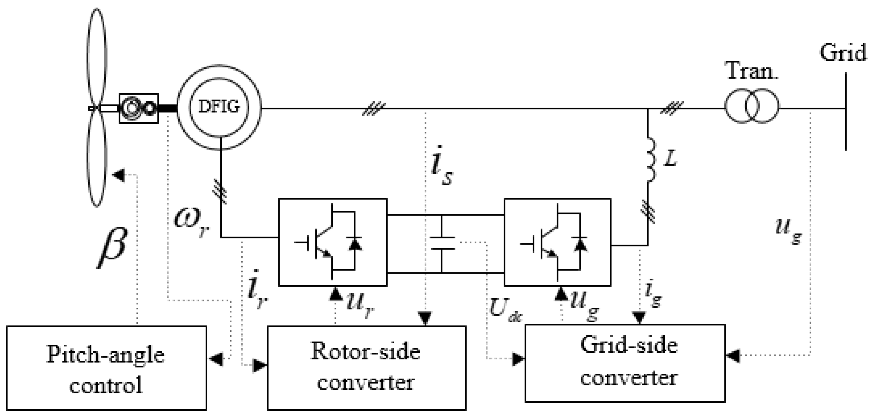
As shown in
Figure 1, the DFIG model consists of a wind turbine blade model, an asynchronous generator model, and a DFIG controller, including a rotor-side converter (RSC) and grid-side converter (GSC).
After the wind energy in the air is captured by the wind turbine, the energy is transferred by the gearbox from the low-speed shaft to the high-speed shaft of the induction generator. The stator side of the induction generator is directly connected to the power grid, and the rotor side is connected to the power grid through the back-to-back converter.
Due to certain energy loss in the actual operation process, the wind energy utilization coefficient
cp is introduced to describe the ability of wind turbines to convert wind energy into mechanical energy, and the expression of a wind turbine blade model, which captures the mechanical power from the wind, is
where
cp,
λ, and
β represent the power coefficient, tip-speed ratio, and pitch angle, respectively,
ρ is the air density,
A represents the area swept by the wind blade, and
vw is the wind speed.
cp is a non-linear function as given by [
26]:
where
where
ωr is the rotor speed of the WTG,
R is the radius of the blade, and
A = π
R2.
Figure 2 displays the RSC and GSC controllers, respectively. The control system includes two cascaded controllers: the outer controller (power or voltage controller) and inner controller (current controller). The rotor-side converter controller regulates the active and reactive power input to the power grid by controlling the rotor-side
d-
q axis voltage, and the process is as follows: the current references for the
d- and
q-components are obtained by passing a PI controller. Then, the current for the
d- and
q-components is adjusted with the measured current feedback values. The voltage commands for the
d- and
q-components are obtained as follows [
27]:
where
ird,
irq,
urdref, and
urqref are the rotor current and rotor voltage references for
dq-axis components, respectively;
Pref,
P,
Qref, and
Q are the active power and reactive power references and measurements, respectively;
kp1,
kp2,
kp3,
kp4,
ki1,
ki2,
ki3, and
ki4 are the control gains of PI
1, PI
2, PI
3, and PI
4 for GSC and RSC, respectively;
Lr,
Lm, and
Ls are the inductances of rotor, stator, and magnetizing, respectively;
ωs is the synchronous angular velocity;
σ is the intermediate variable;
σ = 1 −
Lm2/(
LsLr); and
ψs is the flux of the stator winding in a synchronous coordinate system.
The power reference for the
MPPT operation is obtained by bringing Formula 4 into Formula 1; it is labeled as
PMPPT and is expressed as follows:
where
kg is a constant coefficient,
λopt represents the optimal value of
λ, and
cp,max is the maximum value of
cP.
A de-loading operation could be achieved by reducing kg via over-speed control and pitch control, which is widely employed for frequency regulation.
To accomplish this, when modifying the setting of the control coefficient (kg) in (6), point
A (which corresponds to the MPPT mode) moves to the de-loading curves (left-hand or right-hand side) with dynamics, as shown in
Figure 3. Such dynamics can be employed to suppress the frequency fluctuations to release power or store redundant power.
3. Variable-Power-Tracking-Operation-Based Frequency Regulation Scheme
At present, the frequency modulation strategy based on a DFIG is mainly divided into two directions: power reserve control and rotor kinetic energy control. Power reserve control is divided into rotor overspeed control and pitch angle control, which make the DFIG run at a sub-optimal operating point by increasing the rotor speed or reducing the pitch angle, respectively, to save the frequency modulation power method. Although the frequency regulation power is output by the DFIG, the long-term operation of the DFIG at a sub-optimal operating point decreases the fan operation economy.
Based on the kinetic energy control of the rotor, the action of frequency regulation is only carried out when the frequency exceeds the limit, avoiding the economic decline of the DFIG. The preset power trajectory control makes the DFIG switch to the frequency regulation mode after the DFIG detects the frequency exceeding the limit, and its output power is output according to the preset power curve. However, the power trajectory cannot take into account the system frequency and the DFIG’s own state in real time; thus, there is a risk that the DFIG will stall or the potential of frequency modulation will be wasted. Virtual inertia control achieves fast frequency regulation by coupling the frequency regulation power with the system frequency. When the frequency modulation power is decoupled from the MPPT operation, the frequency modulation effect is weakened. Therefore, this paper proposes a DFIG variable-power-tracking-operation-based frequency regulation scheme by combining power trajectory and virtual inertia control.
The storable and releasable energy for the DFIG’s Δ
Es and Δ
Er, respectively, can be represented as follows:
where
ωmin and
ωmax are the minimum and maximum rotor speeds of the WTG, respectively, and
HDFIG represents the inertia of the WTG.
Thus, as in (8) and (9), with different wind speed conditions, the ability to achieve frequency regulation is different, and it is thereby necessary to determine a suitable control parameter to achieve effective frequency regulation performance.
To suppress system frequency fluctuations, the WTG could absorb or release the electric power from the grid or to the grid; thus, the variable-power-tracking-operation-based frequency regulation scheme is proposed. The power reference expression is the same as that in (9).
where
kFR is the frequency deviation-dependent control parameter.
During the over-frequency section, the kFR value should be less than the kg value to store the power to the WTG; during the under-frequency section, kFR should be greater than kg to release the power to the grid.
To improve the frequency regulation capability,
kFR is defined as follows:
where α is the participation factor for smoothing frequency fluctuations with a negative sign. The main idea of this paper is to carry out frequency support for DFIG variable power tracking control; parameter a is the key parameter of the proposed strategy, and its selection affects the frequency regulation performance of the DFIG. The selection of its value needs to be analyzed on a case-by-case basis. In the future, different methods will be used to further explore the method of setting coefficient A and the optimal solution.
As in (10), when Δf > 0, kFR should be less than kg so that the output power of the WTG decreases following frequency deviation; when Δf < 0, kFR should be greater than kg so that the output power of the WTG increases following frequency deviation.
Figure 4 illustrates the control parameter for the variable-power-tracking-operation-based frequency regulation scheme across different
α settings. It is apparent that the control parameter escalates with larger frequency excursions. Moreover, with higher
α settings, the control parameter’s rate of change intensifies, which proves to be advantageous in suppressing frequency excursions.
In
Figure 5, the response of the variable-power-tracking-operation-based frequency regulation scheme is depicted across various α settings. It is evident that the control parameter dynamically adjusts as the frequency excursion fluctuates, and it is particularly noticeable during significant frequency excursions. Furthermore, the adaptability of the proposed scheme can be fine-tuned by utilizing different
α values.
In general, this paper establishes a coupling relationship between the frequency deviation and the control coefficient and proposes a variable-power-tracking-operation-based frequency regulation scheme for a DFIG to adapt to different operating conditions, give full play to the frequency regulation potential of a DFIG, and stabilize the system frequency.
4. Model System and Case Studies
To verify the effectiveness of the variable-power-tracking-operation-based frequency regulation scheme under different wind power permeability conditions, a simulation system including a DFIG and conventional thermal power units is built based on Matlab/Simulink, as shown in
Figure 6. The conventional thermal power unit is a synchronous generator set equipped with a governor and an automatic voltage regulator; the load is represented by a constant power load model.
The wind farm comprises 25 sets of 5 MW doubly fed induction generators (DFIGs). The modeling details of the DFIG are presented in
Section 2. The specific parameters of the DFIG are listed in
Table 1 [
28].
Four conventional synchronous generators (SGs) are included in the system: two rated at 150 MVA and two at 200 MVA. To simplify the modeling of the power grid, we assume these SGs to operate as steam turbine generators with a droop setting of 5.0%. Additionally, we employ the IEEEX1 standard for voltage control. The inertia time constants are set to 5 s for the 200 MVA SGs and 4.3 s for the 150 MVA SGs. In addition, the results obtained with various settings are investigated.
To evaluate the effectiveness of the variable-power-tracking-operation-based frequency regulation scheme, the maximum over- and under-frequency excursions and root mean square of frequency excursion (Δ
fRMS), f, are employed. Δ
fRMS and
fmax for OFE and UFE are calculated using (11) and (12), respectively. Obviously, small Δ
fmax and smoothing Δ
fRMS indicate better performance in suppressing frequency excursions.
where
fnom is the nominal system frequency.
To verify the effectiveness of the strategy, a power system model with high wind power permeability is built on the Matlab2021b/Simulink simulation platform. Considering the complex change in load disturbance in actual operation, a continuous disturbance is set, as shown in
Figure 7. Under different wind speeds and wind power permeability conditions, according to [
29], the frequency modulation effects of MPPT, traditional droop control (
kp = 20), the adaptive frequency support strategy (method I), and the proposed strategy (
a = 50; method II) are compared, and the example settings are shown in
Table 2.
4.1. Case 1: Wind Speed of 8.0 m/s; Wind Power Penetration of 20%
As shown in
Figure 8 and
Table 3, the simulation result of Case 1 shows that the disturbance occurs at 40 s. Because the MPPT operation of the fan does not respond to the system frequency fluctuation, the maximum and minimum frequencies are 49.06 Hz and 50.96 Hz, respectively, under continuous disturbance, which seriously threatens the safe operation of the system. When a DFIG adopts traditional droop control, the DFIG takes the rotor kinetic energy as the energy source and outputs frequency modulation powers of −0.103–0.0511 p.u. to suppress frequency fluctuation, and the maximum and minimum frequencies are reduced to 49.14 Hz and 50.79 Hz.
When the DFIG adopts method I for frequency regulation, the fan output frequency regulation power is increased due to the influence of adaptive frequency regulation parameters, and the maximum and minimum system frequencies are reduced to 49.18~50.54 Hz. However, due to the constraint of the rotor speed, the frequency regulation potential of the DFIG is not fully utilized, and the rotor is only 0.8538~0.9838 p.u.
When the DFIG adopts the strategy proposed in this paper (method II), the kinetic energy of the DFIG rotor is utilized more, and the rotational speed ranges from 0.7970 to 0.9940 p.u., the output is −0.2555~0.1386 p.u. regarding the frequency regulation power, and the maximum and minimum frequencies are reduced to 49.25 Hz and 50.54 Hz. This is because the proposed strategy considers the phenomenon that the MPPT output decreases due to the decrease in the DFIG speed and controls the kFR to make it change in the range of 0.1295~0.7860 p.u, thus avoiding the weakening effect of the MPPT output’s decrease on the power, making full use of the rotor kinetic energy and restraining frequency fluctuation.
4.2. Case 2: Wind Speed of 10 m/s; Wind Power Penetration of 20%
With the increase in the wind speed, the stored energy of the fan rotor increases. In order to reflect the effectiveness of the proposed strategy under different frequency modulation reserves (rotor kinetic energy) of the DFIG, the wind speed is increased to 10 m/s, and the simulation results are shown in
Figure 9 and
Table 4.
Because the MPPT of the fan does not participate in frequency modulation, its frequency fluctuation is the same as that of Example 1. The DFIG adopts droop control, the output power becomes −0.0981–0.0488 p.u., and the maximum and minimum frequencies become 49.14 Hz and 50.80 Hz. When the DFIG adopts method I, although the rotor speed increases, the maximum and minimum frequency is reduced to 49.29~50.60 Hz. However, the control coefficient is limited by the rotor speed, and the frequency regulation effect is not strong; when the frequency rises, the frequency regulation effect is especially lower than the frequency regulation effect when the DFIG adopts method II. When the DFIG adopts the strategy proposed in this paper (method II), the output power is coupled with the rotor speed, while the rotor speed is positively related to the wind speed. Affected by the increase in the wind speed, the output frequency modulation power of the DFIG is increased to −0.3844~0.2042 p.u., and the system frequency is improved to 49.35~50.35 Hz. The kinetic energy of the rotor is fully utilized. Therefore, the proposed strategy can still maintain excellent frequency modulation performance under different wind speeds.
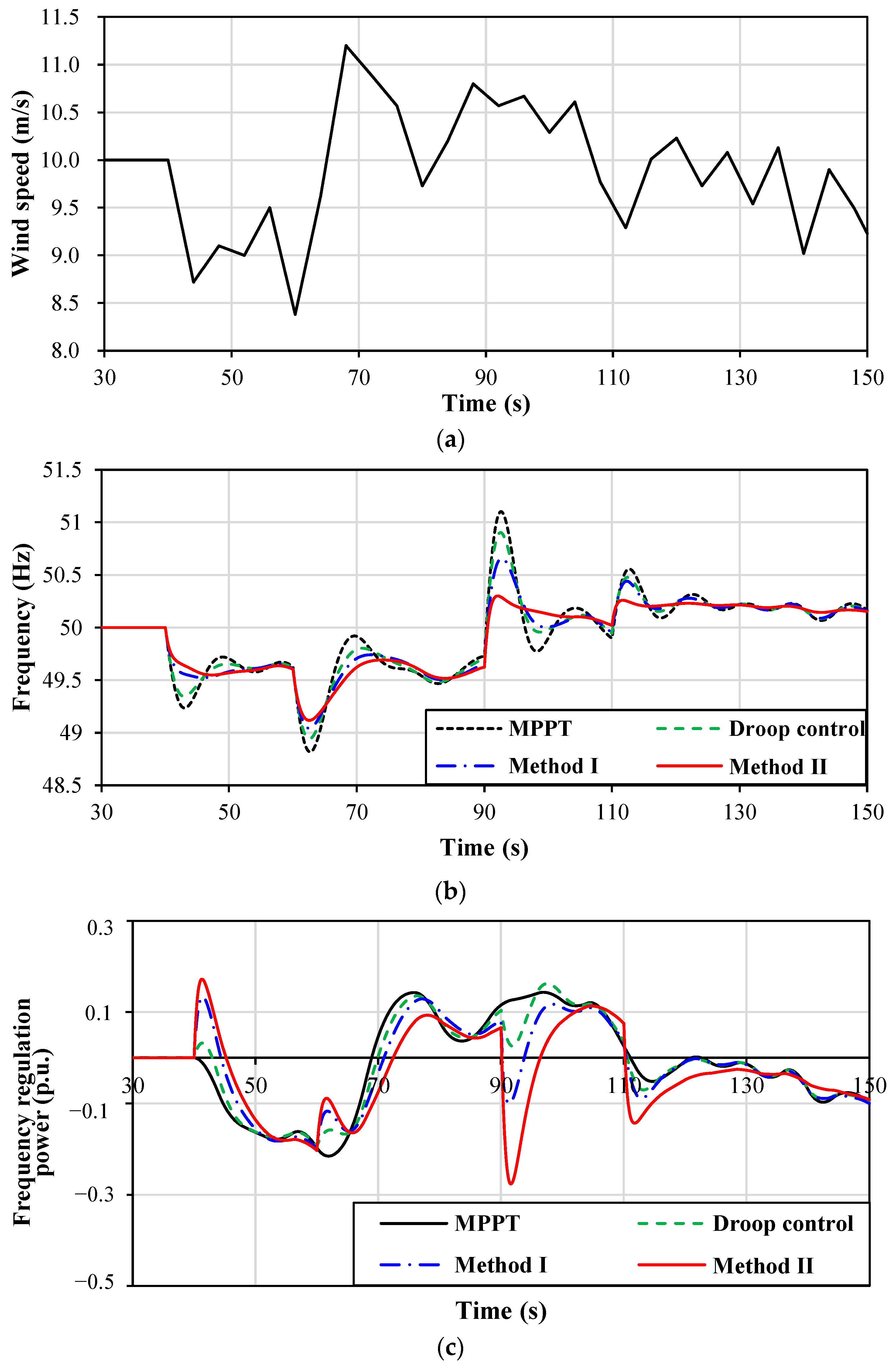
4.3. Case 3: Variable Wind Speed of 10 m/s; Wind Power Penetration of 25%
To simulate the actual operation of the DFIG, an example of random wind speed is added, and the wind power permeability is increased to 25%. The simulation results are shown in
Figure 10.
With the increase in the wind’s electric permeability, the inertia of the system further decreases, and the maximum and minimum frequencies of the system increase to 48.82 Hz and 51.10 Hz under the operation of MPPT. Affected by the increase in wind power permeability, the overall rotor kinetic energy of the DFIG increases, and the output frequency modulation power is increased to −0.1932–0.1623 p.u. by droop control, but its frequency modulation control is decoupled from the rotational speed, and due to the “weakening effect” of MPPT output reduction, the maximum and minimum frequencies are simultaneously reduced to 48.94 Hz and 50.90 Hz. When the DFIG adopts method I, compared with method II proposed in this paper, the frequency regulation effect is not ideal, and the frequency fluctuation range is reduced to 49.05~50.65 Hz. The frequency modulation strategy proposed in this paper can output more power (0.8762~1.243 p.u.), and the frequency improvement effect is better (49.12~50.29 Hz), as shown in
Table 5.
Combined with the three examples, the root mean square difference between the system frequency and rotor speed is calculated, and the summary diagram is shown in
Figure 11. As seen in
Figure 11a, from the perspective of system frequency modulation, the frequency dispersion of the proposed strategy is small, which can better suppress the system frequency fluctuation. The reason for this is that the rotor speed of the fan has a large dispersion in the frequency modulation process, which gives the fan greater frequency modulation potential, as shown in
Figure 11b. Compared with traditional droop control, the method proposed in this paper can give full play to the frequency modulation potential of the wind turbine and provide additional power for frequency modulation. By appropriately increasing the value of k in the gain coefficient, the DFIG-assisted frequency modulation effect is better, and more economic benefits are brought to the wind farm.
5. Conclusions
This paper proposes a variable-power-tracking-operation-based frequency regulation scheme for a DFIG which employs a frequency excursion-based control parameter to suppress frequency excursion under various wind speeds and disturbances. To this end, the improved SFR is modeled; then, the frequency regulation characteristics of the WTG are investigated. The frequency excursion-based control parameter is determined. Simulations based on Matlab/Simulink verify the effectiveness of the proposed variable-power-tracking-operation-based frequency regulation strategy.
The simulation results clearly indicate that the proposed frequency regulation strategy effectively mitigates fluctuations in the system frequency under various wind patterns and disturbances. As the control coefficient increases, the frequency regulation capability improves. Therefore, the suggested strategy is beneficial to mitigate frequency fluctuations.
The operating conditions faced by a DFIG are extremely complex, further aggravating the difficulty of confirming parameter a. Additionally, the frequency modulation capability of a DFIG should be analyzed on a case-by-case basis, and the control strategy should constantly be modified and improved. Therefore, the frequency regulation strategy of a DFIG operating under more complex conditions will be further studied in the future.
Author Contributions
Conceptualization, S.X. and Z.Y. (Zhiguo Yang); methodology, Z.Y. (Zhilong Yin) and F.Y.; software, Z.Y. (Zhiguo Yang) and Z.W.; validation, Z.Y. (Zhiguo Yang) and F.Y.; formal analysis, S.X. and F.Y.; investigation, F.Y. and Z.W.; resources, Z.Y. (Zhiguo Yang) and S.X.; data curation, Z.W. and S.X.; writing—original draft preparation, S.X. and Z.W.; writing—review and editing, S.X. and F.Y.; visualization, F.Y.; supervision, Z.Y. (Zhilong Yin) and Z.Y. (Zhiguo Yang); project administration, F.Y. All authors have read and agreed to the published version of the manuscript.
Funding
This research was funded by the National Natural Science Foundation of China, grant number 52307208.
Data Availability Statement
Data is contained within the article.
Conflicts of Interest
Author Shuilian Xue was employed by the company Nanjing Moral Testing and Certification Co., Ltd. The remaining authors declare that the research was conducted in the absence of any commercial or financial relationships that could be construed as a potential conflict of interest.
References
- Zhang, J.; Li, J. Hybrid deloading control strategy in mmc-based wind energy conversion systems for enhanced frequency regulation. Energies 2024, 17, 1253. [Google Scholar] [CrossRef]
- Yang, D.; Wang, X.; Chen, W.; Yan, G. Adaptive frequency droop feedback control-based power tracking operation of a DFIG for temporary frequency regulation. IEEE Trans. Power Syst. 2024, 39, 2682–2692. [Google Scholar] [CrossRef]
- Castillo, O.C.; Andrade, V.R.; Rivas, J.J.R.; González, R.O. Comparison of power coefficients in wind turbines considering the tip speed ratio and blade pitch angle. Energies 2023, 16, 2774. [Google Scholar] [CrossRef]
- Wang-Hansen, M.; Josefsson, R.; Mehmendovic, H. Frequency controlling wind power modeling of control strategies. IEEE Trans. Sustain. Energy 2013, 4, 954–959. [Google Scholar] [CrossRef]
- Guo, X.; Yuan, X.; Zhu, D.; Zou, X.; Hu, J. Evaluation and optimization of DFIG-based WTs for constant inertia as synchronous generators. IEEE Trans. Power Electron. 2024, 39, 10453–10464. [Google Scholar] [CrossRef]
- Björk, J.; Pombo, D.V.; Johansson, K.H. Variable-speed wind turbine control designed for coordinated fast frequency reserves. IEEE Trans. Power Syst. 2022, 37, 1471–1481. [Google Scholar] [CrossRef]
- Lyu, X.; Groß, D. Grid forming fast frequency response for PMSG-based wind turbines. IEEE Trans. Sustain. Energy 2024, 15, 23–38. [Google Scholar] [CrossRef]
- Bao, W.; Ding, L.; Kang, Y.C.; Sun, L. Closed-loop synthetic inertia control for wind turbine generators in association with slightly over-speeded deloading operation. IEEE Trans. Power Syst. 2023, 38, 5022–5032. [Google Scholar] [CrossRef]
- Margaris, I.D.; Papathanassiou, S.A.; Hatziargyriou, N.D.; Hansen, A.D.; Sørensen, P. Frequency control in autonomous power systems with high wind power penetration. IEEE Trans. Sustain. Energy 2012, 3, 189–199. [Google Scholar] [CrossRef]
- Yang, D.; Jun, L.; Jin, Z. Sequential frequency regulation strategy for DFIG and battery energy storage system considering artificial deadbands. Int. J. Electr. Power Energy Syst. 2024, 155, 109503. [Google Scholar] [CrossRef]
- Yang, D.; Kang, Y.C.; Park, J.-W. Power smoothing of a variable-speed wind turbine generator. Int. J. Ctrl. Autom. Syst. 2021, 19, 11–19. [Google Scholar] [CrossRef]
- Jiang, Q.; Hong, H. Wavelet-based capacity configuration and coordinated control of hybrid energy storage system for smoothing out wind farm fluctuations. IEEE Trans. Power Syst. 2013, 28, 1363–1372. [Google Scholar] [CrossRef]
- Pegueroles-Queralt, J.; Bianchi, F.D.; Gomis-Bellmunt, O. A power smoothing system based on supercapacitors for renewable distributed generation. IEEE Trans. Ind. Electron. 2015, 62, 343–350. [Google Scholar] [CrossRef]
- Akram, U.; Khalid, M. A coordinated frequency regulation framework based on hybrid battery-ultracapacitor energy storage technologies. IEEE Access 2018, 6, 7310–7320. [Google Scholar] [CrossRef]
- Wang, C.; Li, J.; Hu, Y. Frequency control of isolated wind-diesel microgrid power system by double equivalent-input-disturbance controllers. IEEE Access 2019, 7, 105617–105626. [Google Scholar] [CrossRef]
- Kim, Y.; Kang, M.; Muljadi, E.J.; Park, W.; Kang, Y.C. Power smoothing of a variable-speed wind turbine generator in association with the rotor speed-dependent gain. IEEE Trans. Sustain. Energy 2017, 8, 990–999. [Google Scholar] [CrossRef]
- Lyu, Y.J.; Xu, Z. A novel control strategy for wind farm active power regulation considering wake interaction. IEEE Trans. Sustain. Energy 2020, 11, 618–628. [Google Scholar] [CrossRef]
- Lyu, J.Z.; Jia, Y.; Xu, Z.; Po Wong, K. Coordinated control strategies of PMSG-based wind turbine for smoothing power fluctuations. IEEE Trans. Power Syst. 2019, 34, 391–401. [Google Scholar] [CrossRef]
- Zhao, X.; Yan, Z.; Xue, Y.; Zhang, X.-P. Wind power smoothing by controlling the inertial energy of turbines with optimized energy yield. IEEE Access 2017, 5, 23374–23382. [Google Scholar] [CrossRef]
- Jeon, H.; Kang, Y.C.; Park, J.-W.; Il Lee, Y. PI control loop–based frequency smoothing of a doubly-fed induction generator. IEEE Trans. Sustain. Energy 2021, 12, 1811–1819. [Google Scholar] [CrossRef]
- Lyu, X.; Zhao, Y.; Groß, D.; Liu, T. Receding horizon control based secondary frequency regulation for power systems with wind energy integration. Int. J. Electr. Power Energy Syst. 2022, 142, 108282. [Google Scholar] [CrossRef]
- Zhang, X.; Wang, Y.; Fu, Y.; Xu, L. A novel method for obtaining virtual inertial response of DFIG-based wind turbines. Wind Energy 2016, 19, 313–328. [Google Scholar] [CrossRef]
- Liu, H.; Li, M.; Liu, L.; Shi, J. Frequency trajectory planning-based transient frequency regulation strategy for wind turbine systems. IEEE J. Emerg. Sel. Top. Power Electron. 2022, 10, 3987–4000. [Google Scholar] [CrossRef]
- Zhou, Y.; Zhu, D.; Zou, X.; He, C.; Hu, J.; Kang, Y. Adaptive temporary frequency support for DFIG-based wind turbines. IEEE Trans. Energy Convers. 2023, 38, 1937–1949. [Google Scholar] [CrossRef]
- Xu, M.; Jin, Y.; Ma, J.; Wang, C.; Liu, P. Fuzzy frequency droop control of DFIG wind turbine generators adapted to continuous changes in wind speeds. IEEE Access 2023, 11, 115011–115024. [Google Scholar] [CrossRef]
- Ullah, N.R.; Thiringer, T.; Karlsson, D. Temporary primary frequency control support by variable speed wind turbines—Potential and applications. IEEE Trans. Power Syst. 2008, 23, 601–612. [Google Scholar] [CrossRef]
- Fernandez, L.M.; Garcia, C.A.; Jurado, F. Comparative study on the performance of control systems for doubly fed induction generator wind turbines operating with power regulation. Energy 2008, 33, 1438–1452. [Google Scholar] [CrossRef]
- Eto, J.H. Use of Frequency Response Metrics to Assess the Planning and Operating Requirements for Reliable Integration of Variable Renewable Generation; Lawrence Berkeley National Laboratory: Berkeley, CA, USA, 2011. [Google Scholar]
- Lee, J.; Jang, G.; Muljadi, E.; Blaabjerg, F.; Chen, Z.; Kang, Y.C. Stable short-term frequency support using adaptive gains for a DFIG-based wind power plant. IEEE Trans. Energy Convers. 2016, 31, 1068–1079. [Google Scholar] [CrossRef]
| Disclaimer/Publisher’s Note: The statements, opinions and data contained in all publications are solely those of the individual author(s) and contributor(s) and not of MDPI and/or the editor(s). MDPI and/or the editor(s) disclaim responsibility for any injury to people or property resulting from any ideas, methods, instructions or products referred to in the content. |
© 2024 by the authors. Licensee MDPI, Basel, Switzerland. This article is an open access article distributed under the terms and conditions of the Creative Commons Attribution (CC BY) license (https://creativecommons.org/licenses/by/4.0/).


