
An Efficient SS-MAC Protocol for IEEE 802.15.4-Based WSNs of Cluster Tree Topology


Abstract
1. Introduction
- (1)
- It uses a hybrid CSMA/TDMA technique and channel-hopping mechanism to reduce inter-node interference;
- (2)
- It improves the sharable slot (SS) algorithm proposed in [8] to wake up tree nodes level-by-level according to the network topology, thereby reducing the energy consumption caused by node listening;
- (3)
- It employs an 8-bit short address to identify member nodes, thereby reducing the control overhead of nodes;
- (4)
- It improves the knapsack algorithm proposed in [3] to determine the number of slots and assignment order for each member node;
- (5)
- The whole network adjusts the duty cycle and the length of the sharable slot periodically to better adapt to the dynamic traffic load.
2. Related Work
3. The Proposed SS-MAC Protocol
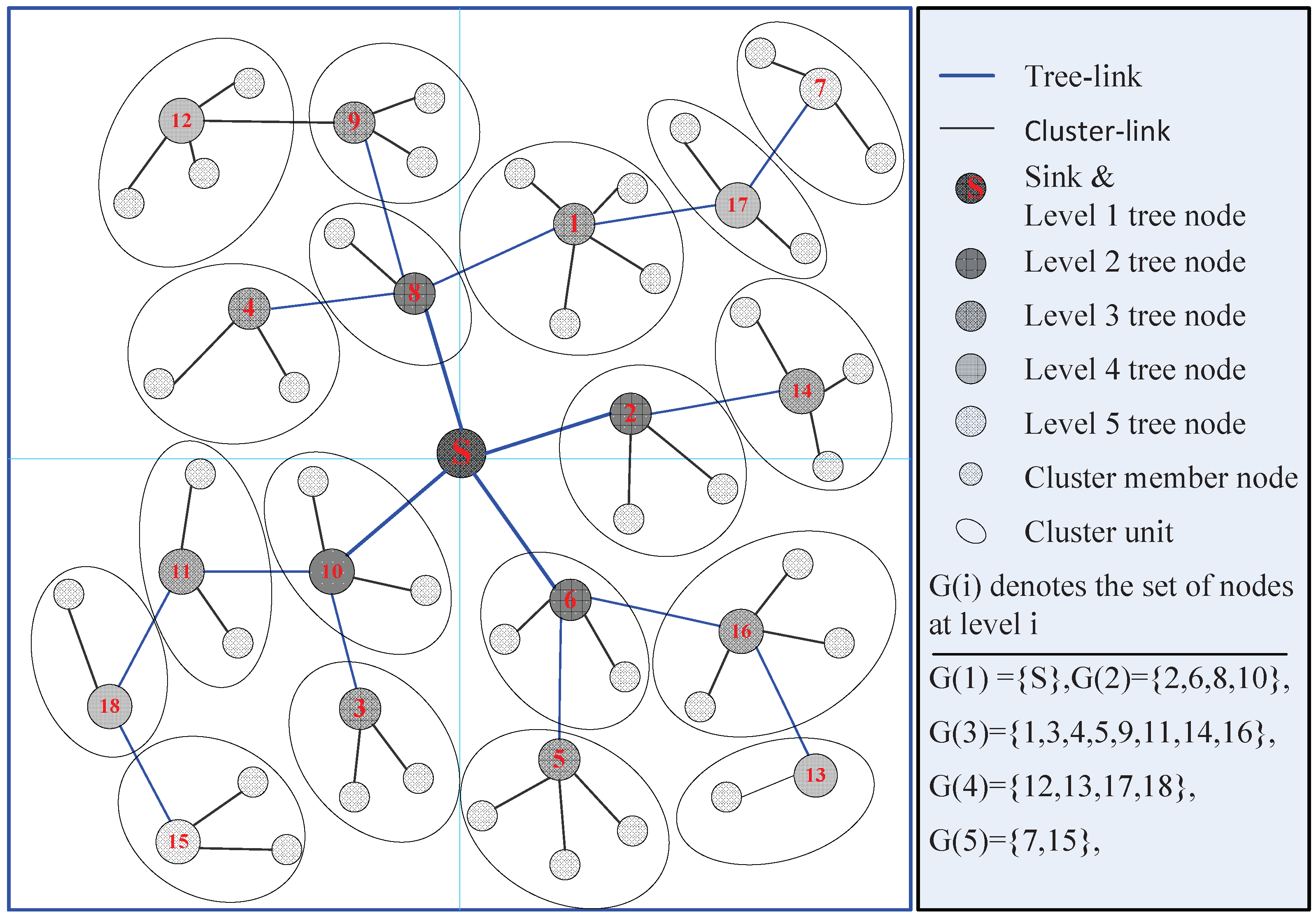
3.1. Network Phase Design
3.2. Setup Phase (SP)
3.2.1. Routing Construction Period (RCP)
3.2.2. Control Period (CP)
3.2.3. Contention Access Period (CAP)
3.2.4. Data Collection Period (DCP)
- (1)
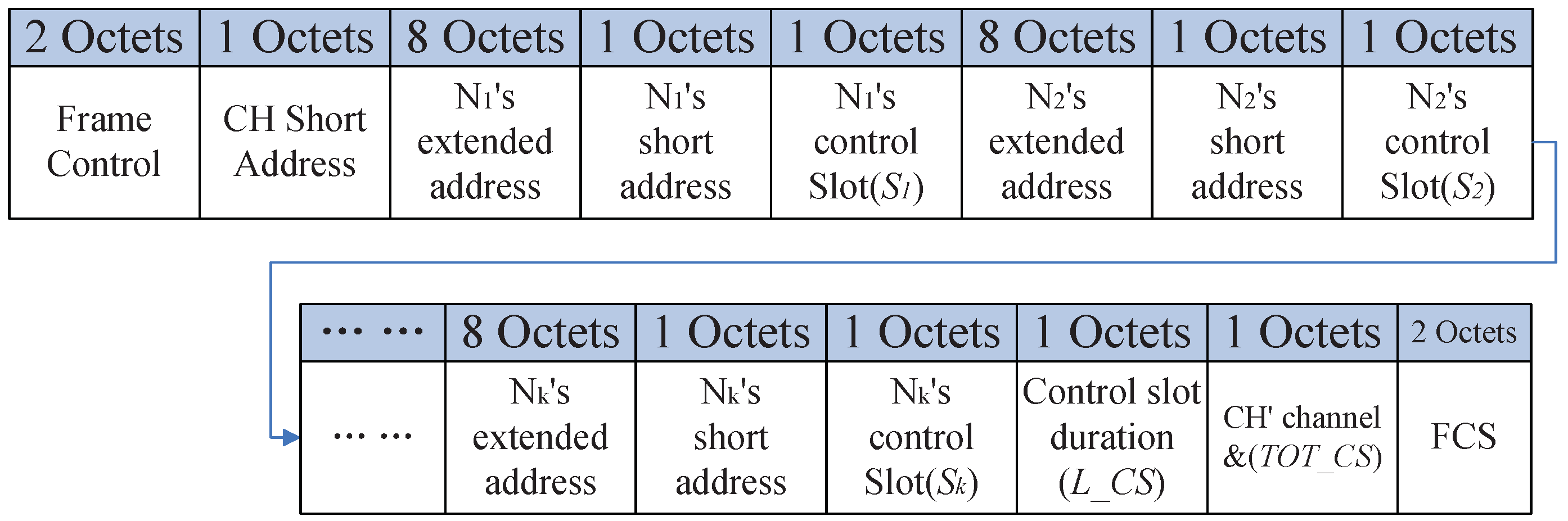
- DS_ANN message
- (2)
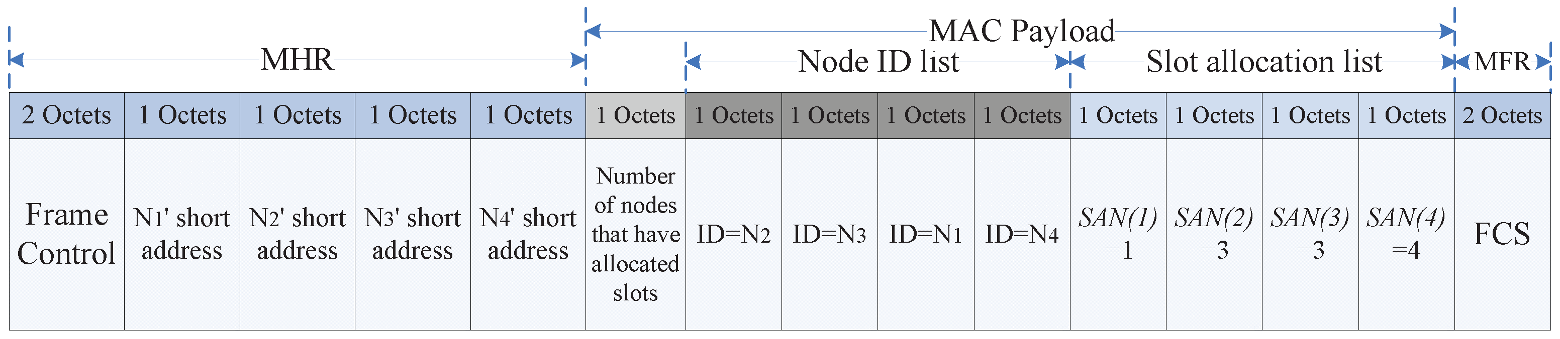
- Knapsack optimization algorithm
- (1)
- If the total number of requested slots is less than or equal to W, that is, , the output of Algorithm 1 is . CH can allocate slots as requests, but the order of transmission is optimized by Algorithm 2.
- (2)
- If the total number of requested slots is greater than W, that is, CH cannot meet the data slot requests of all nodes, Algorithm 1 is implemented to provide an optimal slot allocation scheme .
| Algorithm 1 SS-MAC Knapsack optimization algorithm. |
|
- (3)
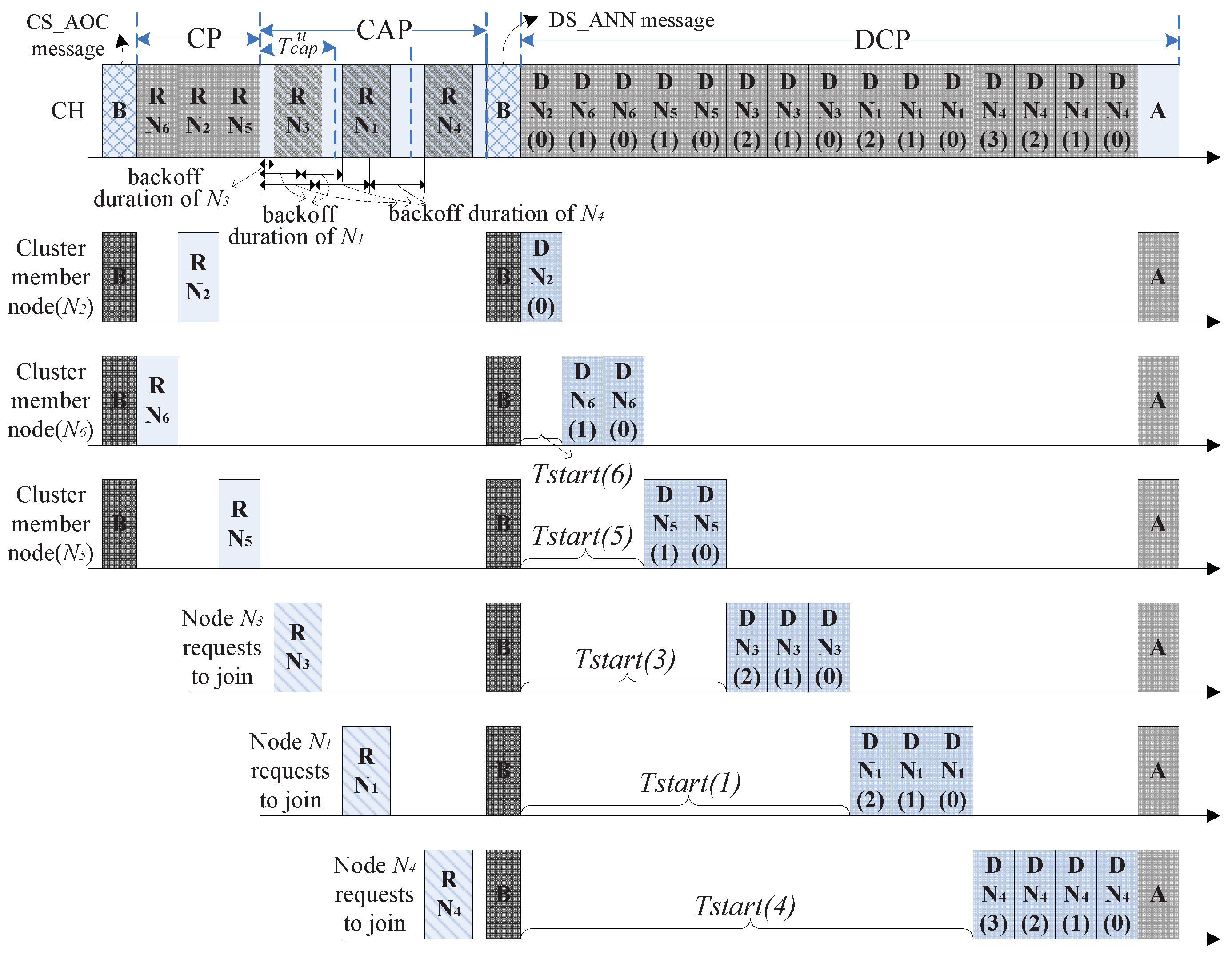
- Data collection process in DCP
| Algorithm 2 SS-MAC node sorting algorithm. |
|
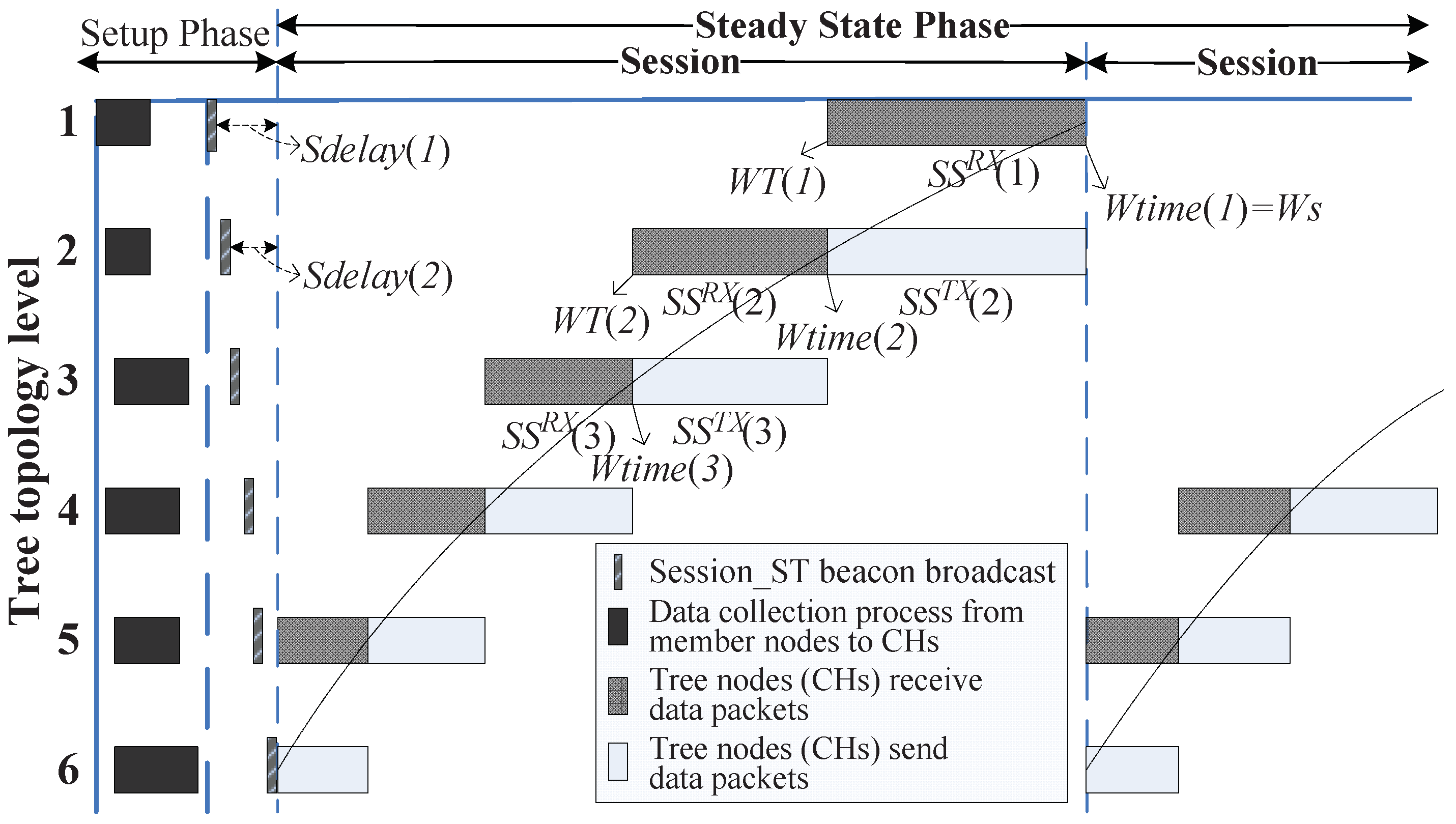
3.3. Steady State Phase (SSP)
3.3.1. Session _ST Beacon
3.3.2. Sharable Slot
- (1)
- The lower the level (i.e., the closer to the sink) of a tree node, the more data the tree node needs to send, and the longer it takes to send the data;
- (2)
- CH has a data fusion function. The amount of data that a tree node sends to its parent is less than the sum of the amount that the node receives from its children and the amount that it collects from member nodes. It leads to increasing the amount of data level-by-level from the leaf nodes to sink.
3.3.3. Transmission Mechanism
4. Modeling Analysis
4.1. and
4.2. Average Packet Waiting Time Analysis
- (1)
- Packet arrives during CP. CP consists of control slots allocated to member nodes to reserve data slots. If packet l of member node i arrives before the start of its slot in CP, packet l can complete the reservation in this CP and complete transmission in the upcoming DCP, as moment ➀, shown in Figure 8—the packet waiting time is ; if packet l arrives after the start of its slot in CP, as moment ➁, the node i will complete reservation in the next CP, and the packet waiting time will increase significantly to .
- (2)
- Packet arrives outside CP. Node i needs to reserve slot for sending packet l in the next CP and sends it in the subsequent DCP. Figure 9 shows the scenarios when packet l arrives at CAP, DCP and vacation. The packet waiting times are , and , respectively.
4.3. Energy Consumption Analysis
5. Performance Evaluation
5.1. Average Waiting Time in SS-MAC
5.2. Energy Consumption in SS-MAC
5.3. Performance Comparison of the Four Protocols
6. Conclusions
Author Contributions
Funding
Data Availability Statement
Conflicts of Interest
References
- Althobaiti, A.S.; Abdullah, M. Medium Access Control Protocols for Wireless Sensor Networks Classifications and Cross-Layering. Procedia Comput. Sci. 2015, 65, 4–16. [Google Scholar] [CrossRef]
- Zhuo, S.; Wang, Z.; Song, Y.Q.; Wang, Z.; Almeida, L. A Traffic Adaptive Multi-Channel MAC Protocol with Dynamic Slot Allocation for WSNs. IEEE Trans. Mob. Comput. 2016, 15, 1600–1613. [Google Scholar] [CrossRef]
- Alvi, A.N.; Bouk, S.H.; Ahmed, S.H.; Yaqub, M.A.; Sarkar, M.; Song, H. BEST-MAC: Bitmap-assisted Efficient and Scalable TDMA based WSN MAC protocol for Smart Cities. Multidiscip. Open Access J. 2016, 4, 312–322. [Google Scholar] [CrossRef]
- Ajmi, N.; Helali, A.; Lorenz, P.; Mghaieth, R. SPEECH-MAC: Special purpose energy-efficient contention-based hybrid MAC protocol for WSN and Zigbee network. Int. J. Commun. Syst. 2020, 34, 1–18. [Google Scholar] [CrossRef]
- Deng, M.; Chen, H.; Xie, L. DCO-MAC: A Hybrid MAC Protocol for Data Collection in Underwater Acoustic Sensor Networks. Sensors 2018, 18, 2300. [Google Scholar] [CrossRef] [PubMed]
- Rambabu, C.; Prasad, V.V.K.D.V.; Prasad, K. Multipath Cluster-based Hybrid MAC Protocol for Wireless Sensor Networks. Int. J. Wirel. Microw. Technol. (IJWMT) 2020, 10, 1–16. [Google Scholar] [CrossRef]
- Won, M.; Park, T.; Son, H.S. Asym-MAC: A MAC Protocol for Low-Power Duty-Cycled Wireless Sensor Networks with Asymmetric Links. IEEE Commun. Lett. 2014, 18, 809–812. [Google Scholar] [CrossRef]
- Oh, H.; Ngo, C.T. A Slotted Sense Multiple Access Protocol for Timely and Reliable Data Transmission in Dynamic Wireless Sensor Networks. IEEE Sens. J. 2018, 18, 2184–2194. [Google Scholar] [CrossRef]
- Hai, T.; Zhou, J.; Padmavathy, T.V.; Md, A.Q.; Jawawi, D.N.A.; Aksoy, M. Design and validation of lifetime extension low latency MAC protocol (LELLMAC) for wireless sensor networks using a hybrid algorithm. Sustainability 2022, 14, 15547. [Google Scholar] [CrossRef]
- Xiao, Z.; Zhou, J.; Yan, J.; He, C.; Jiang, L.; Trigoni, N. Performance Evaluation of IEEE 802.15.4 with Real Time Queueing Analysis. Ad Hoc Netw. 2018, 73, 80–94. [Google Scholar] [CrossRef]
- Wang, F.; Li, D.; Zhao, Y. Analysis of CSMA/CA in IEEE 802.15.4. IET Commun. 2011, 5, 2187–2195. [Google Scholar] [CrossRef]
- Kim, T.H.; Choi, S. Priority-based Delay Mitigation for Event-Monitoring IEEE 802.15.4 LR-WPANs. IEEE Commun. Lett. 2006, 10, 213–215. [Google Scholar]
- Biswas, S.; Roy, S.D. Chandra, A Single CCA for IEEE 802.15.4 Networks: A Cross Layer Energy Model. IET Netw. 2018, 8, 203–210. [Google Scholar] [CrossRef]
- Zhu, J.; Tao, Z.; Lv, C. Performance improvement for IEEE 802.15.4 CSMA/CA Scheme In Large-Scale Wireless Multi-Hop Sensor Networks. IET Wirel. Sens. Syst. 2013, 3, 93–103. [Google Scholar] [CrossRef]
- Shin, S.Y. Hroughput Analysis of IEEE 802.15.4 Network Under IEEE 802.11 Network Interference. AEU Int. J. Electron. Commun. 2013, 67, 686–689. [Google Scholar] [CrossRef]
- Bouazzi, I.; Bhar, J.; Atri, M. Analysis of the IEEE 802.15.4 MAC Parameters to Achieve Lower Packet Loss Rates. Procedia Comput. Sci. 2013, 73, 443–451. [Google Scholar] [CrossRef]
- Mukhtar, M.F.; Shiraz, M.; Shaheen, Q.; Ahsan, K.; Akhtar, R.; Changda, W. RBM: Region-Based Mobile Routing Protocol for Wireless Sensor Networks. Wirel. Commun. Mob. Comput. 2021, 2021, 6628226. [Google Scholar] [CrossRef]
- Rishiwal, V.; Singh, O.; Yadav, M. ECMR: Energy Constrained Mobile Routing for Wireless Sensor Networks. Wirel. Pers. Commun. 2022, 124, 2939–2964. [Google Scholar] [CrossRef]
- Nam, Y.; Choi, H.; Shin, Y.; Park, S.; Lee, E. Expected Area-Based Real-Time Routing Protocol for Supporting Mobile Sinks in Wireless Sensor Networks. Electronics 2022, 11, 3350. [Google Scholar] [CrossRef]
- Dongya, C. Routing optimization algorithm based on mobile agent for wireless sensor networks. J. Comput. Methods Sci. Eng. 2023, 23, 773–780. [Google Scholar]
- Taleb, A.A.; Haija, A.A.Q.; Odeh, A. Efficient Mobile Sink Routing in Wireless Sensor Networks Using Bipartite Graphs. Future Internet. 2023, 15, 182. [Google Scholar] [CrossRef]
- Elmonser, M.; Chikha, B.H.; Attia, R. Mobile routing algorithm with dynamic clustering for energy large-scale wireless sensor networks. IET Wirel. Sens. Syst. 2020, 10, 208–213. [Google Scholar] [CrossRef]
- Lin, Z.; Lin, M.; Cola, T.D.; Wang, J.B.; Zhu, W.P.; Cheng, J. Supporting IoT with Rate-Splitting Multiple Access in Satellite and Aerial-Integrated Networks. IEEE Internet Things J. 2021, 8, 11123–11134. [Google Scholar] [CrossRef]
- Park, P.; Marco, P.D.; Soldati, P.; Fischione, C.; Johansson, K.H. A generalized Markov Chain Model for Effective Analysis of Slotted IEEE 802.15.4. In Proceedings of the 2009 IEEE 6th International Conference on Mobile Adhoc and Sensor Systems, Macau, China, 12–15 October 2009; pp. 130–139. [Google Scholar]


| L | The highest level of topology tree | Packet payload of member node (bit) | |
| Data rate of PHY (bps) | Packet overhead of member node (bit) | ||
| Data sensing rate of member node i (bps) | Packet payload sent by tree node (bit) | ||
| Session duration (s) | Packet overhead sent by tree node (bit) | ||
| Sharable slot index | ACK frame length of tree node (bit) | ||
| Data fusion degree of CHs | Node transmitting power (W) | ||
| Packet arrival rate of member node i (pps) | Node receiving power (W) | ||
| Avg packet arrival rate of member nodes (pps) | Node sleep & channel listening power (W) | ||
| Max packet arrival rate of member nodes (pps) | TREE_CON message frame length (bit) | ||
| Max number of member nodes in a cluster | CH_DEC message frame length (bit) | ||
| Max number of children of a tree node | CS_AOC message frame length (bit) | ||
| Total number of tree nodes in network | JC_REQ message frame length (bit) | ||
| Total number of non-cluster-head nodes | DS_REQ message frame length (bit) | ||
| Number of sessions in SSP | DS_ANN message frame length (bit) | ||
| Data slot duration (s) | Session_ST beacon frame length (bit) |
| LELLMAC | SSMA | ||||||||
|---|---|---|---|---|---|---|---|---|---|
| Packet size (Bytes) | 64 | Packet size (Bytes) | 10 | ||||||
| Sending and receiving slot (ms) | 60 | Receiver-initiated mini slot (ms) | 5 | ||||||
| Average idle (sleep) duration (ms) | 100 | Sender-initiated mini slot (ms) | 15 | ||||||
| The maximum number of nodes a node can send packets | 3 | Duration of one data collection round (s) | 1.6 | ||||||
| IEEE 802.15.4 MAC | SS-MAC | Common parameters of the four protocols | |||||||
| System size (frames) | 51 | 0.7 | (bps) | 19,200 | |||||
| Minimum value of backoff exponent (macMinBE) | 3 | 0.005 | (bit) | 88 | |||||
| Maximum value of backoff exponent (macMaxBE) | 5 | (bit) | 48 | (W) | 0.08 | ||||
| Max number of backoffs (macMaxCSMABackoffs) | 4 | (bit) | 48 | (W) | 0.07 | ||||
| Max number of retries (macMaxFrameRetries) | 3 | (bit) | 968 | (W) | 0.07 | ||||
| MAC frame payload (bit) | 968 | (bit) | 48 | ||||||
| Overhead added in PHY layer (bit) | 48 | 50 | |||||||
| Translation coefficient from frame to slot (bit/slot) | 80 | ||||||||
| L | 3 | 4 | 5 | |||||||||
| 3 | 5 | 3 | 5 | 3 | 5 | |||||||
| 5 | 10 | 5 | 10 | 5 | 10 | 5 | 10 | 5 | 10 | 5 | 10 | |
| 13 | 13 | 31 | 31 | 40 | 40 | 156 | 156 | 121 | 121 | 781 | 781 | |
| 60 | 120 | 150 | 300 | 195 | 390 | 775 | 1550 | 600 | 1200 | 3900 | 7800 | |
| 7.495 | 3.747 | 3.352 | 1.676 | 2.241 | 1.120 | 0.716 | 0.358 | 0.706 | 0.353 | 0.157 | 0.078 | |
| 0.768 | 0.768 | 1.718 | 1.718 | 2.570 | 2.570 | 8.046 | 8.046 | 8.156 | 8.156 | 36.523 | 36.523 | |
| 0.444 | 0.463 | 0.919 | 0.938 | 1.345 | 1.364 | 4.083 | 4.102 | 4.138 | 4.157 | 18.322 | 18.341 | |
Disclaimer/Publisher’s Note: The statements, opinions and data contained in all publications are solely those of the individual author(s) and contributor(s) and not of MDPI and/or the editor(s). MDPI and/or the editor(s) disclaim responsibility for any injury to people or property resulting from any ideas, methods, instructions or products referred to in the content. |
© 2024 by the authors. Licensee MDPI, Basel, Switzerland. This article is an open access article distributed under the terms and conditions of the Creative Commons Attribution (CC BY) license (https://creativecommons.org/licenses/by/4.0/).
Share and Cite
Li, S.; Yuan, Y.; Pan, G. An Efficient SS-MAC Protocol for IEEE 802.15.4-Based WSNs of Cluster Tree Topology. Electronics 2024, 13, 2520. https://doi.org/10.3390/electronics13132520
Li S, Yuan Y, Pan G. An Efficient SS-MAC Protocol for IEEE 802.15.4-Based WSNs of Cluster Tree Topology. Electronics. 2024; 13(13):2520. https://doi.org/10.3390/electronics13132520
Chicago/Turabian StyleLi, Suoping, Youyi Yuan, and Guodong Pan. 2024. "An Efficient SS-MAC Protocol for IEEE 802.15.4-Based WSNs of Cluster Tree Topology" Electronics 13, no. 13: 2520. https://doi.org/10.3390/electronics13132520
APA StyleLi, S., Yuan, Y., & Pan, G. (2024). An Efficient SS-MAC Protocol for IEEE 802.15.4-Based WSNs of Cluster Tree Topology. Electronics, 13(13), 2520. https://doi.org/10.3390/electronics13132520