Article

Research on Control Strategy of PMSG-PWM Power Generation System with Tidal Energy

School of Electrical Engineering, Naval University of Engineering, Wuhan 430033, China
*
Author to whom correspondence should be addressed.
Electronics 2024, 13(13), 2455; https://doi.org/10.3390/electronics13132455
Submission received: 27 May 2024 / Revised: 13 June 2024 / Accepted: 20 June 2024 / Published: 22 June 2024

Abstract

:
Aiming at the characteristics of machine-side output instability and the wide-range variation in the tidal energy PMSG-PWM power generation system, we propose a control scheme with a high anti-interference capability applied to the PWM rectifier. The outer voltage loop adopts sliding mode control (SMC) with the variable exponential convergence law based on expanded state observer (ESO). By compensating the perturbation observation value into the sliding mode controller in advance, it improves the robustness and response speed of the system and suppresses the direct current (DC)-side voltage jitter phenomenon. The current inner loop combines model prediction (MP) with direct power control (DPC). By introducing time-delay compensation, it improves the control accuracy, reduces the machine-side harmonic content, and enables the system to maintain unit power factor operation despite external disturbances. Simulation and experiment results show that, under the wide range of PMSG output, the PMSG-PWM power generation system adopting the “ESO_SMC+MDPDC” scheme has a fast dynamic regulation of DC output voltage, obvious vibration suppression effect, low harmonic content of the current on the PMSG side, and fast current tracking speed, which verify the feasibility of applying this system to the field of tidal energy generation.

1. Introduction

PMSG generates a magnetic field from the rotor permanent magnet without the need for complex electrical excitation devices. The volume and weight of the generator are greatly reduced, and the structure is optimized. At the same time, the copper consumption of the rotor is eliminated, and the heat load is concentrated on the stator, resulting in higher heat dissipation efficiency. PMSG has been widely used in many fields, such as electric vehicles, new energy power generation, and ship power systems [1,2]. However, in the application of tidal power generation systems, the unstable and uncontrollable characteristics of tidal flow-rate velocity lead to real-time changes in the amplitude and frequency of PMSG-output AC power. The magnetic field generated by PMSG permanent magnets is fixed, which makes it difficult to achieve a stable control of the output voltage, so in order to obtain stable and reliable electric power, it is necessary to combine the PMSG with rectifier devices to achieve a stable output of electric power after electric energy conversion [3,4].
An uncontrolled rectifier plus a DC-DC converter and thyristor phase-controlled rectifier circuits have poor regulation fastness and a low power factor, which are not in line with the unstable application requirements of tidal power generation. They also inject a large number of high-current harmonics into the generator side during the operation process, which lead to a significant increase in generator eddy current loss, hysteresis loss, etc., making the work efficiency lower and the temperature of the motor higher, and, in severe cases, leading to the demagnetization of permanent magnet materials [5,6]. Compared with the above two circuits, the PWM rectifier has many advantages, such as low AC current harmonics, a high power factor, high accuracy of voltage regulation, adjustable output voltage, and strong anti-interference capability [7,8], which is more suitable for the PMSG back-stage rectifier circuit. Figure 1 shows the block diagram of the tidal power generation system. The water turbine converts the kinetic energy of the tidal fluid into mechanical energy, which is then converted from low-speed, high-torque mechanical energy to high-speed, low-torque mechanical energy through gearbox acceleration. The PMSG converts the mechanical energy into electrical energy, and the output AC power is rectified and stabilized by the PWM rectifier before being integrated into the power grid.
The PMSG-PWM power generation system has a broad application and development space, so the study of control strategies for this system is very meaningful. Reference [1] proposed a decoupling calculation method for inductance-free parameters applied to the PMSG-PWM power generation systems based on PI control theory, which improves the system’s response speed and robustness performance. Aiming at the issues of large overshoot and long adjustment time in the output voltage of the PMSG-PWM power generation system based on classical PI controller, reference [4] designs a fuzzy adaptive PI controller to improve the dynamic and steady-state performance and the anti-interference performance of the system, but it has not been experimentally verified. Reference [9] studies the PWM control algorithm on the generator side of permanent-magnet synchronous wind power generation systems and proposes a full-power inverter control strategy. The experimental results show that this control strategy can effectively address the instability problem of PMSG power generation caused by wind speed changes. Reference [10] addressed the issues of the inconvenient regulation of PMSG excitation and high-voltage adjustment rates in electric drive mining cars. A PWM rectifier based on a new convergence law SMC is adopted to achieve stable control on the DC voltage side during load changes. Reference [11] proposes a position-free control strategy based on the sliding mode observer method. The simulation and experimental results have shown that the proposed method can accurately and effectively estimate the rotor position angle and make the rectifier system output a voltage waveform that meets the standard. This solves the problem of the traditional PMSG-PWM power generation system’s mechanical sensor performance being easily affected by external environmental changes, which leads to a decrease in system reliability. Aiming at the issue of insufficient load to current ratio in high-speed and large capacity PMSG, the topology of PWM rectifiers is improved by using power transistor series or parallel connections to increase the equivalent switching frequency of the rectifiers in reference [12]. The effectiveness of the topology and the correctness of the entire PMSG system control algorithm are demonstrated through experiments.
PWM rectifiers are essentially a class of nonlinear systems, and SMC, as a nonlinear control strategy, is sensitive to changes in system parameters and to external disturbances and has high robustness, so it is very suitable for the control of tidal-energy PMSG-PWM power generation systems with variable characteristics. Aiming at the weak anti-interference ability of three-phase Vienna rectifiers, reference [13] introduces the adaptive super-spiral sliding mode observer into the MPC control, which solves the problem of gain selection caused by external disturbances, ensures the accuracy of the prediction models, and effectively weakens the adverse impact of chattering on system performance. Reference [14] proposes a fuzzy SMC strategy based on a super twisted ESO, which limits the DC voltage regulation error to a bounded region, effectively reduces the chattering phenomenon, and improves the DC voltage regulation performance. Reference [15] proposes a control strategy that combines the adaptive-gain generalized hyper distortion algorithm and the improved hyper distortion observer for three-level Neutral Point Clamped (NPC) converters, which combines the advantages of high-transient performance and low jitter effects and improves the robustness of the system. Reference [16] introduces a high-order SMC into the variable exponential gain super-distortion algorithm, further improving the anti-interference ability of the three-level NPC converter. Compared with the PI control, the direct power control does not require a complex parameter-tuning process, has a relatively simple structure, and can effectively improve the dynamic response speed of the system. Reference [17] improves the MPDPC strategy based on T-type-grid connected inverters, achieving an optimal vector prediction scheme for constant switching frequency operation. At the same time, it greatly simplifies the calculation process and improves the dynamic and static performance of the system. In response to the characteristics of vehicle-mounted rectifiers being easily affected by changes in train operating conditions (power level, circuit parameters, etc.), reference [18] proposes a dual closed-loop control strategy of an active disturbance rejection control and MPDPC, which integrates reactive power compensation measures based on the inner membrane principle into the power prediction stage, effectively solving the problem of reactive power offset caused by a circuit parameter mismatch. Reference [19] improves the traditional MPDPC implementation of fixed frequency control by selecting the three voltage vectors corresponding to the minimum cost function to calculate the duty cycle, effectively reducing the computational load and time and improving the dynamic performance of the system.
The unstable characteristics of tidal energy generation require a higher anti-interference performance for the PMSG-PWM power generation system. Combined with the above, this article proposes a novel dual closed-loop strategy applied to the tidal energy PMSG-PWM power generation system. The voltage outer loop adopts SMC based on a new convergence law and introduces ESO into the outer loop control; the current inner loop improves MPDPC and introduces the time-delay compensation control, which eliminates the delay problem of the sampling cycle and accelerates the dynamic response speed of the system. Finally, the performance of the proposed control strategy in terms of response speed and anti-interference ability is verified through simulation and experiment.

2. Main Circuit Topology and Mathematical Model

PMSG Mathematical Model

Without considering the magnetic resistance of the iron core, ignoring losses such as eddy current hysteresis and the damping winding of the rotor, and assuming that the excitation magnetic field and the armature reaction magnetic field are both sinusoidal distributions, the PMSG voltage equation in a three-phase stationary coordinate system is obtained as follows [20]:
u a = e a R s i a L s d i a d t u b = e b R s i b L s d i b d t u c = e c R s i c L s d i c d t
In this equation, u a , u b , u c are the output terminal voltage of PMSG, e a , e b , e c are the three-phase inverse electromotive force, i a , i b , i c are the three-phase stator current, and L s , R s are the equivalent inductance and resistance of PMSG, respectively.
By analyzing Equation (1), it can be seen that PMSG can be equivalent to a series circuit of inverse electromotive force, inductance, and resistance. Figure 2 shows a simplified structural model of the PMSG-PWM power generation system.
Assuming that the PMSG inverse electromotive force is a three-phase symmetrical sine wave, and the switching device is equivalent to an ideal switch, voltage equations are written for each phase circuit according to Kirchhoff’s voltage law, and current equations are written for the upper node of the DC-side capacitor according to current law. After simplification, the mathematical model of the PWM rectifier in the three-phase stationary coordinate system is obtained as [20]:
L d i a d t d i b d t d i c d t = e a e b e c R i a i b i c u dc 2 3 1 3 1 3 1 3 2 3 1 3 1 3 1 3 2 3 S a S b S c C d u dc d t = i a S a + i b S b + i c S c u dc R L
In this equation, L = L s + L 0 , R = R s + R 0 ( L 0 is the external inductor and R 0 is the external resistance), S a , S b , S c represents the switching function of the three-phase bridge arm switching tubes of the PWM rectifier; S = 1 represents the conduction of the corresponding bridge arm’s upper tube, the turn-off of the lower tube; and S = 0 is the opposite. C is the filtering capacitor, u dc is the DC output voltage, and R L is the load resistance.
Combining the practical needs of the voltage and current loop controllers, we convert the mathematical model to two-phase stationary coordinate systems and two-phase rotation using the Clark transform and the Park transform, respectively. The mathematical model in the ( α , β ) coordinate system is:
L d i α d t = R i α v α + e α L d i β d t = R i β v β + e β C d u dc d t = S α i α + S β i β u dc R L
In this equation, v α = S α u dc and v β = S β u dc indicate the AC phase voltages of a PWM rectifier.
The mathematical model in the (d, q) coordinate system is:
L d i d d t = R i d + ω L i q S d u dc + e d L d i q d t = R i q ω L i d S q u dc + e q C d u dc d t = S d i d + S q i q u dc R L

3. Design of the Dual Closed-Loop Controllers

3.1. Voltage Outer Loop Controller

3.1.1. Design of Sliding Mode Controller Based on Variable Exponential Convergence Law

The key to designing a sliding mode controller is to determine the sliding mode surface function and to select a convergence law suitable for the system. The specific implementation process can be refined into two steps: first, the initial state of the system approaches the sliding mode surface from any spatial position, and second, it slides along the sliding mode surface to the equilibrium point position.
Next, we select state variables and sliding surface equations:
e 1 = s 1 = i q * i q e 2 = s 2 = u dc * u dc
If we adopt the classical exponential convergence law s ˙ = ε sgn ( s ) k s (in the formula, ε is the switching function coefficient, and k is the exponential convergence law coefficient), in the first process, a large value of the switching coefficient will cause the state point of the system to still maintain a large speed after moving to the vicinity of the sliding mode surface, making the state point oscillate up and down on the sliding mode surface and resulting in the phenomenon of vibration jitter; however, blindly lowering the value of ε to reduce the impact of vibration causes the system response to slow when the system state point is far from the sliding surface. Taking into account the above issues, this article improves the classical exponential convergence law and adopts the following convergence law:
s ˙ = arctan e ε sgn ( s ) k s   ( ε > 0 , k > 0 )
In this equation, the meanings of ε and k are the same as in the previous text.
According to the stability proof method described in reference [21], it can be concluded that a voltage controller designed with a new convergence law can stabilize the voltage loop of a PWM rectifier. With the introduction of the inverse tangent function, the state variable e is large when the state point of the system is far away from the sliding mode surface, at which time the rate of convergence is large due to the joint action of arctan e ε sgn ( s ) and k s . When the state point of the system moves to the vicinity of the sliding mode surface, k s 0 , arctan e ε sgn ( s ) plays a major role. As the state point continues to approach the sliding mode surface, the state variable e also tends to zero, and the rate of convergence continues to decrease. When the state point arrives at the surface of the sliding mode, arctan e ε sgn ( s ) and k s are both zero, representing the fact that the rate of convergence is zero. From this analysis, it can be seen that the variable exponential convergence law adopted in this article is able to improve the response speed and reduce the jitter effect performance at the same time.
When the system operates in stable operation at unit power factor, in which the reactive component of the AC side current i q = 0 , then it is necessary to set the reference value of the reactive current as i q * = 0 . The DC-side command voltage u dc * is a fixed value, and its derivation result is zero. Associative Equations (4)–(6) can be obtained:
i d = C S d arctan e 2 ε sgn e 2 + k e 2 + u dc C R L
When the system is operating steadily at a unit power factor of i q = 0 and d i d d t = 0 , which is obtained by substituting it into the first term of Equation (4):
S d = e d R i d u dc
In this equation, e d = 3 U rms ( U rms is the effective value of the three-phase power supply voltage on the grid side).
When the system is under a stabilized condition, the voltage outer loop output reference current i d * = i d . Associative Equations (7) and (8) yield, and the voltage outer loop output expression is:
i d * = C u dc e d R i d arctan e 2 ε sgn e 2 + k e 2 + u dc C R L

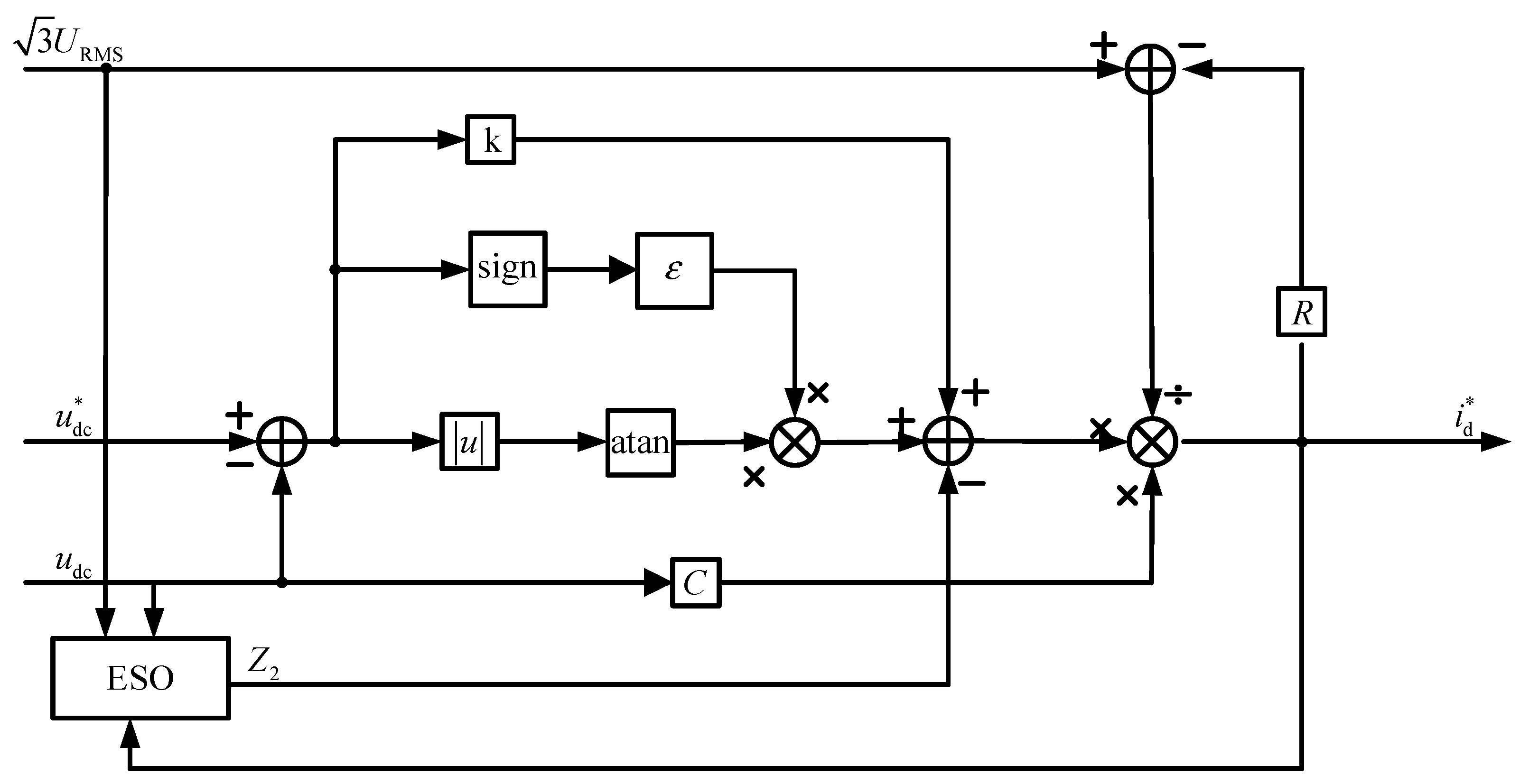
3.1.2. Sliding Mode Controller Design with the Introduction of ESO

In response to the problem of the insufficient sensitivity of SMC to disturbances, such as capacitance and inductance parameter changes and backend load disconnection, ESO is introduced to improve the sensitivity of the system. Reference [22] uses the Lyapunov inverse theorem to prove the convergence of the state error of ESO. We define the external disturbance of the system as T t when the system operates in a steady state at the unit power factor of i q = 0 . Ignoring the equivalent resistance of the inductor on the alternating current (AC) side and combining it with Equation (8), Equation (4) can be rewritten as:
d u dc d t = e d u dc C i d * u dc R L C + T t C + e d u dc C ( i d i d * )
To improve the system’s immunity, the total system disturbance is defined as:
d ( t ) = u dc R L C + T ( t ) C + e d u dc C ( i d i d * )
The total perturbation covers the DC-side voltage, circuit parameters, AC-side current tracking error, and external perturbations.
Associative Equations (10) and (11) are obtained as follows:
d u dc d t = d ( t ) + b ( t ) i d *
In this equation, b ( t ) = e d u dc C .
The analysis shows that the voltage outer loop mathematical model is expanded to a second-order system with the equation of state:
x ˙ 1 ( t ) = x 2 ( t ) + b i d * x ˙ 2 ( t ) = d d ( t ) d t
In this equation, x 1 ( t ) = u dc and x 2 ( t ) = d ( t ) .
According to the ESO principle described in reference [23], the second-order ESO is designed in this article as:
z ˙ 1 = z 2 + b t i d * β 1 ( z 1 x 1 ) z ˙ 2 = β 2 ( z 1 x 1 )
z 1 and z 2 are the observations for u dc and d ( t ) , respectively. β 1 and β 2 are the ESO design parameters.
Substituting the voltage outer loop integrated perturbation d ( t ) into Equation (9), the ESO-based variable-exponential convergence law sliding mode controller is obtained as:
i d * = C u dc e d R i d arctan e 2 ε sgn e 2 + k e 2 z 2
The block diagram of the voltage outer loop control is shown in Figure 3.

3.2. Current Inner Loop Controller

Due to the introduction of the hysteresis loop comparator and switching table, the traditional voltage-directed DPC has the shortcomings of unfixed switching frequency and a high requirement of sensor conversion accuracy. MPC is inclusive of system nonlinear characteristics and constraints, and this article replaces the hysteresis loop comparator and switching table with model prediction to solve the abovementioned frequency immobility problem. For the digital control system’s delay error problem, we introduce the delay compensation. A two-step prediction method is used to eliminate the effect and improve the control accuracy. The design process of the MPDPC-based inner loop controller is derived in detail in the following section.
The active and reactive power of PMSG in a two-phase stationary coordinate system can be expressed as:
p = e α i α + e β i β q = e β i α e α i β
Then, the rate of change of active and reactive power at moment t is:
d p d t = e α d i α d t + i α d e α d t + e β d i β d t + i β d e β d t d q d t = e β d i α d t + i α d e β d t e α d i β d t i β d e α d t
According to the coordinate transformation theory, the PMSG inverse potential is derived with the following relation:
d e α d t = d E m sin ω t d t = ω E m cos ω t = ω e β d e β d t = d E m cos ω t d t = ω E m sin ω t = ω e α
Substituting Equations (3) and (18) into Equation (17), the active and reactive power can be expressed as:
d p d t = 1 L ( e α 2 e α ν α R e α i α + e β 2 e β ν β R e β i β ) + ω ( e α i β i α e β ) d q d t = 1 L ( e α ν β e β ν α + R e α i β R e β i α ) + ω ( e α i α + i β e β )
In a sampling period T , the active and reactive power changes can be obtained as:
Δ p = d p d t T Δ q = d q d t T
Calculated by equations p ( k + 1 ) = p ( k ) + Δ p and q ( k + 1 ) = q ( k ) + Δ q , the active and reactive power at t = k + 1 T can be obtained as:
p ( k + 1 ) = p ( k ) + T L ( e α 2 e α v α R e α i α + e β 2 e β v β R e β i β ) + ω T ( e α i β i α e β ) q ( k + 1 ) = q ( k ) + T L ( e α v β e β v α + R e α i β R e β i α ) + ω T ( e α i α + i β e β )
Similarly, it can be calculated that at t = k + 2 T , the active and reactive power is:
p ( k + 2 ) = p ( k + 1 ) + T L ( e α 2 e α v α R e α i α + e β 2 e β v β R e β i β ) + ω T ( e α i β i α e β ) q ( k + 2 ) = q ( k + 1 ) + 1 L ( e α v β e β v α + R e α i β R e β i α ) + ω T ( e α i α + i β e β )
According to the MPC principle, the objective function is constructed by minimizing the power error sum of squares in each cycle as:
J ( k ) = ( p ref p ( k + 2 ) ) 2 + ( q ref q ( k + 2 ) ) 2
In this equation, p ref is obtained by multiplying the reference current vector from the output of the outer loop controller by the DC-side voltage, and q ref is set to zero to achieve the unit power factor operation.
To obtain the optimal voltage vector, J ( k ) should be at minimum. Set the following:
J ( k ) v α ( k ) = 0 J ( k ) ν β ( k ) = 0
Substituting Equations (16) and (22) into Equation (24), the optimal v α ( k ) , ν β ( k ) are obtained as:
v α ( k ) = e α R i α + ω L i β   L T ( e α 2 + e β 2 ) ( e α ( p ref ( k + 1 ) p ( k + 1 ) ) + e β ( q ref ( k + 1 ) q ( k + 1 ) ) ) v β ( k ) = e β R i β + ω L i α   L T ( e α 2 + e β 2 ) ( e β ( p ref ( k + 1 ) p ( k + 1 ) ) e α ( q ref ( k + 1 ) q ( k + 1 ) ) )
The block diagram of the current inner loop control is shown in Figure 4.
Through the analysis of the dual closed-loop control strategy mentioned above, the overall block diagram of the control system can be obtained as shown in Figure 5.

4. Simulation and Experiment Verification

4.1. Simulation Verification

In order to verify the feasibility of the PMSG-PWM power generation system based on the control strategy proposed in this article and to apply it in the field of tidal generation, we built a platform in Matlab/Simulink (version 2022A) according to Figure 5 to carry out a simulation analysis in which the PMSG, by the inverse electromotive force and inductance, showed the resistance of the series’ circuit equivalent, the ESO_SMC outer loop controller output active reference current i d * , and then obtained the active reference power p ref . In order to achieve the unit power operation, we set the reactive reference current q ref = 0 through the MPDPC inner loop controller to obtain the optimal reference voltage vector v α and v β and through the SVPWM modulation to obtain the switching signal to turn the IGBT device on and off. The research background of this article is the tidal energy generation system for islands. Based on the actual tidal flow rate, a military project in the research projects’ group designed a certain type of PMSG with the rated reaction potential and frequency of “190 V, 25 Hz”, which are the system specific simulation parameters, as shown in Table 1.

4.1.1. Under Rated Condition

Figure 6 shows the DC output voltage waveform. During the startup phase, the actual voltage reached the command voltage in about 0.04 s without voltage overshooting, and the system dynamic response performance was better, which indicates that the variable exponential convergence law enabled the system to enter the sliding mode surface quickly and that it has a high convergence speed. After the actual voltage was stabilized, the voltage fluctuated up and down in a range of 0.07 V or less. It was shown that the introduction of the variable exponential convergence law and the ESO improved the jitter suppression ability of the system significantly, improved the static performance of the voltage loop significantly, and enabled the DC output voltage ripple to be controlled effectively.
Figure 7 shows the waveforms of the inverse electromotive force and current on the A-phase of the PMSG side. After entering the steady state, the current had a high sinusoidal degree, and the system operated at a unit power factor, indicating that the introduction of time-delay compensation in the current inner loop achieved the accurate tracking of the active power (current); Figure 8 shows the results of the Fourier analysis of the A-phase current with a THD value of 2.86%, which meets the established goal of reducing the harmonic content.

4.1.2. PMSG Variable Operating Conditions

To better test the anti-interference ability of the PMSG-PWM system under changes in the tidal flow-rate velocity, the PMSG inverse electromotive force was set to fluctuate up and down by 30%. Figure 9 shows the DC output voltage waveform. It can be seen that, due to the introduction of ESO, the disturbance was compensated in advance into the sliding mode controller, and the two voltage fluctuations were 0.44 V and 0.54 V, respectively. Although there was overshoot, the magnitude was very small, and the impact on the system was small, indicating that the anti-interference effect of this control strategy is very good. The adjustment times were 0.002 s and 0.22 s, respectively, indicating that the system can still maintain a fast response speed in the face of external interference.
Figure 10 shows the waveform of the A-phase inverse electromotive force and current under PMSG variable operating conditions. It can be seen that, at the moment of fluctuation, the current transition of the PMSG side was relatively smooth, the impulse current was small, and it could quickly track the inverse electromotive force after fluctuation, achieving a stable operation per unit power factor.

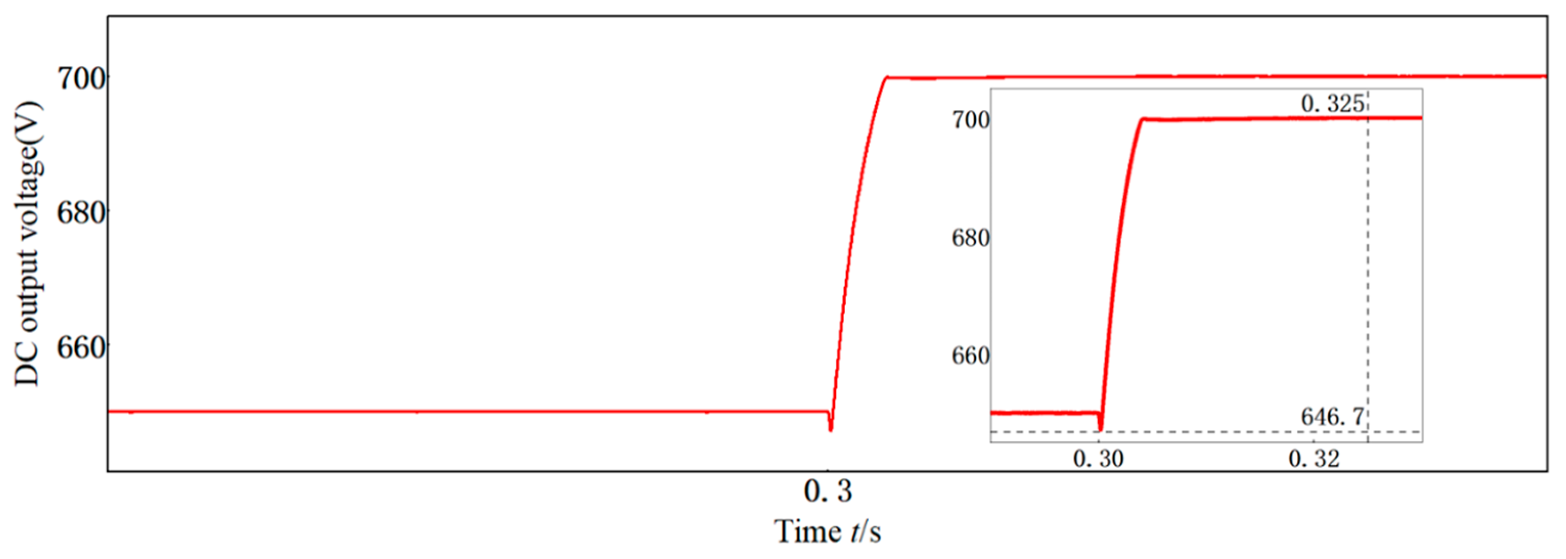
4.1.3. Given DC-Side Voltage Variation

To adapt to different power grid levels on islands and reefs, we analyzed the system performance when the output voltage on the DC-side changed. Figure 11 shows the waveform of the DC-side voltage. The initial given voltage was set to 650 V, and when it rose to 700 V, the system responded quickly. After 0.025 s, the output voltage stabilized to 700 V, and there was no overshoot during the adjustment process, which also indicates that the system has a strong anti-interference ability.

4.2. Experiment Verification

To verify the feasibility of the control strategy proposed in this article, a PMSG-PWM power-generation system experimental platform was built based on a simulation model. Figure 12 shows the prototype. The rated speed of PMSG is 1000 r/min, and the rated inverse electromotive force is 89 V. In actual operation, the inverse electromotive force of the generator cannot be measured, but it is proportional to the speed. Therefore, a rotary encoder was installed on the experimental platform to obtain the real-time signals of rotor position and speed. Based on this, the inverse electromotive force was simulated in real time via the output to the control system. Due to limited motor power, the specific experimental parameters were as follows: the output voltage on the DC side was 175 V, and the other circuit and control system parameters were consistent with the simulation.

4.2.1. Under Rated Condition

We adjusted the PMSG speed to 750 r/min, at which point the inverse electromotive force was 66 V. Figure 13 shows the current waveform on the PMSG side during stable operation, and it can be seen that the input current waveform is a sine wave. Figure 14 shows the waveform of the output voltage on the DC side, indicating that the system has a good voltage stabilization effect.

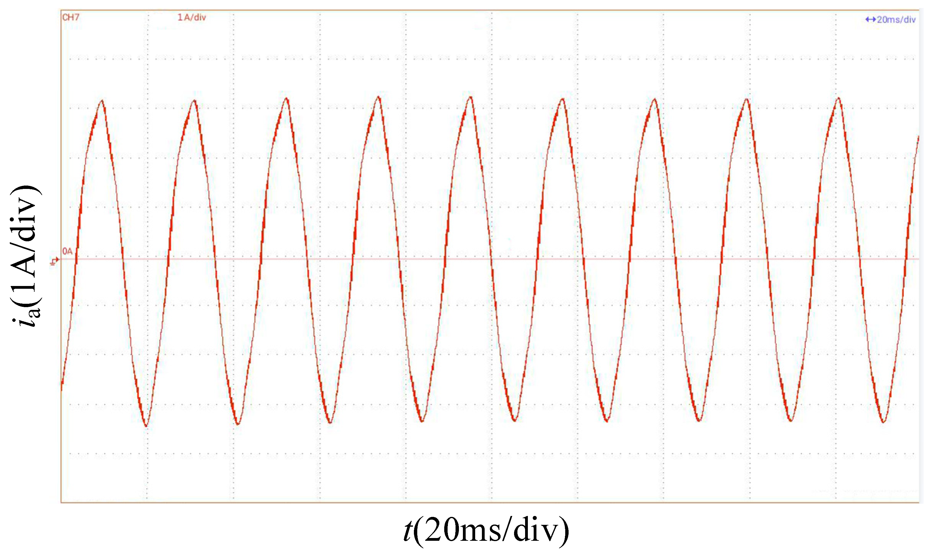
4.2.2. PMSG Variable Operating Conditions

The PMSG speed was jumped from 700 r/min to 900 r/min, with a fluctuation of about 30%. Figure 15 shows the waveform of the DC-side output voltage at the moment of fluctuation. It can be seen that, after about 0.015 s, the DC voltage recovered to 175 V, and the overshoot was about 5 V.

4.2.3. Given DC-Side Voltage Variation

The given voltage on the DC side was suddenly changed from 175 V to 195 V. Figure 16 shows the waveform of the output voltage on the DC side at the moment of adjustment. It can be seen that, after about 0.015 s, the DC voltage was adjusted to 195 V, and the overshoot was within 5 V.

5. Conclusions

Based on the characteristics of unstable and wide-range output on the PMSG side of PMSG-PWM systems in the field of tidal energy generation, this article proposes an “ESO_SMC+MDPDC” dual closed-loop control scheme applied to PWM rectifiers. The outer loop adopts an improved sliding mode convergence law, and the inner loop introduces time-delay compensation. The simulation and experimental results show that the proposed control strategy is feasible and effective, with the following advantages:
(1)
The voltage outer loop adopts the ESO-based variable exponential convergence law SMC, which can respond quickly in the wide-range output of PMSG. The DC output voltage overshoot is very small, and the voltage jitter situation is effectively improved. The overall anti-interference ability of the system is strong.
(2)
The current inner loop adopts the MDPDC scheme that introduces time-delay compensation to improve the current tracking speed and accuracy, ensuring that the system always maintains high-power factor operation under external disturbance conditions. Moreover, the PMSG side current harmonic suppression effect is significant, reducing the harm of harmonics.
(3)
This scheme can still maintain high control accuracy and response speed even when the DC output voltage changes, making it convenient for integrating into different levels of power grids in the later stage.

Author Contributions

Conceptualization, Y.R.; methodology, Y.X.; software, M.Q.; validation, Y.R., Y.X. and M.Q.; formal analysis, Y.R.; investigation, M.Q.; resources, Y.X.; data curation, Y.R.; writing—original draft preparation, Y.R.; writing—review and editing, Y.R.; visualization, Y.X.; supervision, M.Q.; project administration, Y.X.; funding acquisition, Y.X. All authors have read and agreed to the published version of the manuscript.

Funding

This research was funded by the National Natural Science Foundation of China (Grant No. 51877212).

Data Availability Statement

The data that support the findings of this study are available from the corresponding author upon reasonable request.

Conflicts of Interest

The authors declare no conflicts of interest.

References

  1. Cao, K. Research on PWM Rectification Technology of Permanent Magnet Synchronous Generator. Ph.D. Thesis, Nanjing University of Aeronautics and Astronautics, Nanjing, China, 2014. [Google Scholar]
  2. Wu, Y. Research on Voltage Stabilisation Control Technology of Permanent Magnet Synchronous Generator System Based on PWM Rectification. Ph.D. Thesis, Zhejiang University, Hangzhou, China, 2021. [Google Scholar]
  3. Li, Z. Design and Realisation of Three-Phase Tidal Current Energy Generation System. Ph.D. Thesis, Harbin Engineering University, Harbin, China, 2018. [Google Scholar]
  4. Qi, W. Research on Control Strategy of PWM Rectification System for Permanent Magnet Synchronous Generator. Ph.D. Thesis, Shanghai Institute of Electrical Engineering, Shanghai, China, 2019. [Google Scholar]
  5. Song, G. Current Harmonic Analysis of Permanent Magnet Synchronous Generator under PWM Rectifier Control. Ph.D. Thesis, Hunan University, Changsha, China, 2017. [Google Scholar]
  6. Flourentzou, N.; Agelidis, V.G.; Demetriades, G.D. VSC-Based HVDC Power Transmission Systems: An Overview. IEEE Trans. Power Electron. 2009, 24, 592–602. [Google Scholar] [CrossRef]
  7. Yin, Z.; Liu, J.; Zhong, Y. Study and Control of Three-Phase PWM Rectifier Based on Dual Single-Input Single-Output Model. IEEE Trans. Ind. Inform. 2013, 9, 1064–1073. [Google Scholar] [CrossRef]
  8. Gao, Y. Research on Three-Phase Voltage-Type PWM Rectification Technology. Ph.D. Thesis, Harbin Institute of Technology, Harbin, China, 2010. [Google Scholar]
  9. Liu, W.; Ding, M.; Zhang, Z. Research on Machine side PWM Control of Permanent Magnet Synchronous Wind Power Generation System. Electromech. Inf. 2020, 27, 1–3. [Google Scholar]
  10. Fang, K.; Li, B.; Zhang, L. Voltage regulation system of permanent magnet synchronous generator for electric drive mining cars. World Nonferrous Met. 2022, 2, 40–42. [Google Scholar]
  11. Zhang, Y.; Lu, T.; Jian, Z.; Li, Q.; Zhang, W.; Gao, Y. PWM rectification technology based on sliding mode observer without position control. Micromotor 2023, 11, 45–48. [Google Scholar]
  12. Xu, F.; Zhong, Z.; Sun, W.; Jin, M.; Shen, J. Improved topology for PWM rectification of low load to wave ratio permanent magnet synchronous generators. J. Electr. Mach. Control 2018, 2, 41–48. [Google Scholar]
  13. Wang, F.; Yang, A.; Yu, X.; Zhang, Z.; Wang, G. Model free predictive current control of three-phase Vienna rectifier based on adaptive super spiral sliding mode observer. J. Electr. Eng. 2024, 6, 1859–1870. [Google Scholar]
  14. Lin, H.; Liu, J.; Shen, X.; Leon, J.I.; Vazquez, S.; Alcaide, A.M.; Wu, L.; Franquelo, L.G. Fuzzy Sliding-Mode Control for Three-Level NPC AFE Rectifiers: A Chattering Alleviation Approach. IEEE Trans. Power Electron. 2022, 37, 11704–11715. [Google Scholar] [CrossRef]
  15. Shen, X.; Wu, C.; Liu, Z.; Wang, Y.; Leon, J.I.; Liu, J.; Franquelo, L.G. Adaptive-Gain Second-Order Sliding-Mode Control of NPC Converters via Super-Twisting Technique. IEEE Trans. Power Electron. 2023, 38, 15406–15418. [Google Scholar] [CrossRef]
  16. Shen, X.; Liu, J.; Liu, Z.; Gao, Y.; Leon, J.I.; Vazquez, S.; Wu, L.; Franquelo, L.G. Sliding Mode Control of Neutral-Point-Clamped Power Converters with Gain Adaptation. IEEE Trans. Power Electron. 2024, 39, 9189–9201. [Google Scholar] [CrossRef]
  17. Wang, H.; Zhang, H. Study on an Improve Finite-Control-Set -Model Predictive Control (FCS-MPC) Strategy for a T-Type Rectifier with Direct Power Control Strategy. IEEJ Trans. Electr. Electron. Eng. 2021, 18, 442–450. [Google Scholar] [CrossRef]
  18. Wang, X.; Wang, X. Self disturbance rejection model prediction direct power control for dual PWM rectifiers. Power Syst. Prot. Control 2024, 52, 45–56. [Google Scholar]
  19. Dang, C.; Wang, F.; Liu, D.; Tong, X.; Song, W. Sliding mode predictive control of Vienna rectifier based on optimal vector synthesis. Chin. J. Electr. Eng. 2022, 42, 8699–8708. [Google Scholar]
  20. Deng, X. Research on High-Speed PMSG Sensorless PWM Rectification System Based on LCL Filtering. Ph.D. Thesis, Harbin Institute of Technology, Harbin, China, 2011. [Google Scholar]
  21. Chen, C. Research on Sliding Mode Control Strategy of Three Phase Voltage Source PWM Rectifier. Ph.D. Thesis, South China University of Technology, Guangzhou, China, 2020. [Google Scholar]
  22. Shao, X.; Wang, H. Performance analysis of linear extended state observer and its higher-order form. Control Decis. 2015, 30, 815–822. [Google Scholar]
  23. Wang, H.; Huang, H. Performance and Application of Expansion State Observer. Control Decis. Mak. 2013, 28, 1078–1082. [Google Scholar]
Figure 1. Block diagram of the tidal energy generation system.
Electronics 13 02455 g001
Figure 2. Structural model of the PMSG-PWM power generation system.
Electronics 13 02455 g002
Figure 3. Control block diagram of the ESO-based variable-exponential convergence law sliding mode controller.
Electronics 13 02455 g003
Figure 4. Block diagram of MPDPC-based current inner loop controller.
Electronics 13 02455 g004
Figure 5. Overall block diagram of the control system.
Electronics 13 02455 g005
Figure 6. System’s DC-side output voltage waveform.
Electronics 13 02455 g006
Figure 7. Inverse electromotive force and the current waveform of A under the rated state.
Electronics 13 02455 g007
Figure 8. Fourier analysis results of the A-phase current.
Electronics 13 02455 g008
Figure 9. Output voltage on the DC side of PMSG under variable operating conditions.
Electronics 13 02455 g009
Figure 10. A-phase voltage and current waveforms under PMSG variable operating conditions.
Electronics 13 02455 g010
Figure 11. DC-side output voltage waveform.
Electronics 13 02455 g011
Figure 12. Prototype physical object.
Electronics 13 02455 g012
Figure 13. A-phase current waveform.
Electronics 13 02455 g013
Figure 14. DC-side voltage waveform.
Electronics 13 02455 g014
Figure 15. Voltage waveform on the DC side of PMSG under variable operating conditions.
Electronics 13 02455 g015
Figure 16. DC voltage waveform under a given value variation.
Electronics 13 02455 g016
Table 1. Parameters of the PMSG-PWM power generation system.
NumberNotationParameterValue
1 e a , e b , e c Inverse electromotive force of PMSG (V)190
2 L s Equivalent inductance of PMSG (mH)0.3
3 R s Equivalent resistance of PMSG (Ω)0.1
4 L 0 External inductors (mH)1.7
5 R 0 Equivalent resistance of external inductance (Ω)0.01
6 C DC-side capacitance (μF)1600
7 R L Rated load resistance (Ω)100
8 u dc Given DC output voltage (V)650
9 f Sampling frequency (kHz)10
10 ε Switching function coefficients4000
11 k Exponential convergence coefficient218.5
12 β 1 500
13 β 2 80,000
Disclaimer/Publisher’s Note: The statements, opinions and data contained in all publications are solely those of the individual author(s) and contributor(s) and not of MDPI and/or the editor(s). MDPI and/or the editor(s) disclaim responsibility for any injury to people or property resulting from any ideas, methods, instructions or products referred to in the content.

