Article

Dual-Frequency, Dual-Mode Reconfigurable Digital Atmospheric Radar Receiver Design

1
National Space Science Center, Chinese Academy of Sciences, Beijing 100190, China
2
University of Chinese Academy of Sciences, Beijing 100049, China
3
State Key Laboratory of Space Weather, Beijing 100190, China
4
Key Laboratory of Science and Technology on Environmental Space Situation Awareness, Chinese Academy of Sciences, Beijing 100190, China
*
Author to whom correspondence should be addressed.
Electronics 2024, 13(10), 1879; https://doi.org/10.3390/electronics13101879
Submission received: 23 March 2024 / Revised: 28 April 2024 / Accepted: 10 May 2024 / Published: 11 May 2024

Abstract

:
A new dual-frequency, dual-mode reconfigurable digital receiver based on Field-Programmable Gate Array (FPGA) dynamic reconfiguration is proposed, which is based on a common hardware platform of high-bandwidth RF front-end, high-speed data acquisition, and real-time signal processing. The receiver adopts the design of dynamically reconfigurable down-conversion, filter extraction, and matched filtering in the digital domain. In this study, we completed the design and development of the digital receiver, experimental platform construction, and field detection test with hardware and software cooperation. The experimental results show that the receiver achieves full digital reception and signal processing for 53.8 MHz stratosphere–troposphere (ST) detection and 35.0 MHz meteor detection and successfully acquired the number of meteors versus time, the meteor trail, and low-altitude atmospheric radial winds. This dual-frequency, dual-mode reconfigurable digital receiver can be applied to new-generation multifunction integrated radar systems such as dual-frequency ST/meteor radars.

1. Introduction

Atmospheric radio radars, such as medium frequency radars [1,2], meteor radars [3], and MST radars [4], play a significant role in the study of the dynamics and coupling of middle atmosphere and ground weather. They contribute to understanding the physics of atmospheric motion and sudden weather processes, establishing high-precision and high-resolution atmospheric models [5,6,7]. The atmospheric radio radar began to develop towards the trend of multifunctional comprehensive integration. Initially, the detection capability of the ST radar was extended to the mesosphere and the lower thermosphere by combining a meteor detection function with a narrow-beam ST radar operating at a single frequency [8,9] and subsequently by adding an ‘all-sky’ capability to an existing ST radar [10].
Typical operating frequencies for ST atmospheric radars are around 50 MHz [11], and meteor radars usually operate at 30–60 MHz [12], referring to the expression for the count rate given by McKinley [13] (N is the meteor count rate, P T is the transmit power, λ is the radar wavelength, G is the system gain, P R is received power):
N P T 1 2 G λ 3 2 / P R 1 2 ,
Equation (1) indicates that meteor counts are proportional to λ 3 / 2 , so operating a meteor radar near 50 MHz results in fewer counts than for an equivalent 30 MHz radar. To achieve the meteor counting rate of about 30 MHz, the radar can only increase its radar transmit power, but this will make the radar system energy consumption higher; at the same time, higher transmit power will also bring the use of the system maintenance costs and failure rate increase, reliability reduction and other issues. An obvious extension of this single-frequency approach is to operate the radar at two frequencies. Dual-frequency atmospheric radar can optimize the performance of ST wind field detection and meteor wind field detection at the same time, reduce the radar system’s transmit power requirement, and improve the reliability and cost-effectiveness ratio.
With the development of radar technology, more and more new technologies are applied to radar systems, such as dual-frequency high-power transmitters technology, multiple-input-multiple-output (MIMO) sparse electromagnetic vector sensor (EMVS) arrays, Frequency Diverse Array (FDA) MIMO radar system, and reconfigurable digital receiver technology [14,15,16]. In terms of receiver technology, reconfigurable digital receivers possess advantages such as high-speed data acquisition, real-time signal processing, and a general yet highly flexible hardware module [17,18,19], representing the cutting edge in the development of new-generation radar receiver technology. The reconfiguration technology of digital receivers mainly includes (1) enhancing the reconfigurability in the analog domain [20,21] and (2) improving the reconfigurability in the digital domain [22,23]. Enhancing the reconfigurability in the digital domain focuses on achieving digital frequency conversion and a variable data processing workflow, therefore offering greater flexibility and efficiency.
A novel dual-frequency, dual-mode reconfigurable digital receiver is proposed for a new multifunctional integrated atmospheric radar system (e.g., dual-frequency ST meteor radar), which is the first time that the dual-frequency, dual-mode reconfigurable receiver has been applied in the field of atmospheric radio radar. Based on a generic hardware platform with a high-bandwidth RF front-end, high-speed data acquisition, and real-time signal processing, the design and development of the digital receiver were carried out parallelly in hardware and software, followed by experimental verification. Primarily employing designs such as direct RF sampling, digital domain dynamically reconfigurable down-conversion, filter extraction, and matched filtering, the receiver achieves full digital reception and signal processing for 53.8 MHz stratosphere–troposphere (ST) detection and 35.0 MHz meteor detection.

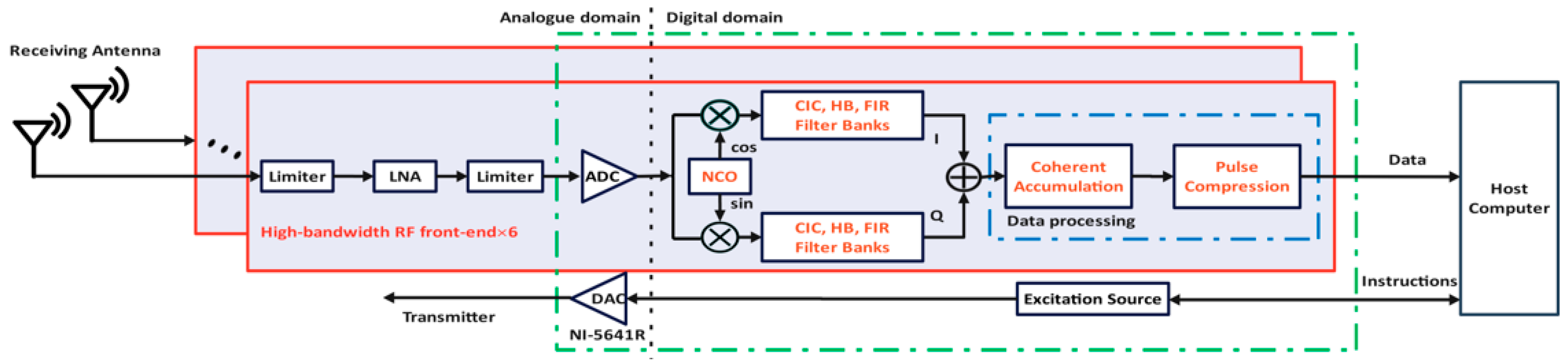
2. Overall Design of Dual-Frequency, Dual-Mode Reconfigurable Digital Receiver

The overall design of the dual-frequency, dual-mode reconfigurable six-channel radio atmospheric radar digital receiver is shown in Figure 1, with five channels dedicated to meteor detection mode (35.0 MHz) and one channel for ST detection mode (53.8 MHz). The RF front-end employs a “broadband low-noise amplification + limiter” design, combined with broadband RF direct sampling, to achieve the reception and amplification of dual-frequency radar echo signals. In the digital domain, FPGA dynamic reconfigurable technology is utilized to adjust the working frequency, bandwidth, pulse width, pulse compression, and coherent accumulation mode of each receiving channel in real-time, achieving dynamic reconfigurability of working modes and parameters. The detection modes and related working parameters of this receiver are listed in Table 1.
The hardware platform of the digital receiver is primarily based on the NI 5641R digital transceiver (Austin, TX, USA) (mainly including AD6654 from Analog Devices (Wilmington, MA, USA) and Virtex-5 series FPGA from Xilinx (San Jose, CA, USA)), with an ADC sampling rate of 120 MHz and a bandwidth of 46.08 MHz. The RF receiving front-end utilizes a PE15A1012 low noise amplifier (with a 40 dB gain and a signal amplification range of 10 MHz~1 GHz) and a two-stage limiter circuit composed of BAV99 switch diodes. The host computer uses a PXIe-3881 embedded host.
The reconfigurable design in the digital domain primarily includes digital down-conversion, extraction filtering, coherent accumulation, and pulse compression with real-time variable parameters. First, the AD6654’s digital mixer is dynamically configured using FPGA, allowing for real-time adjustments to the digital intermediate frequency signal’s center frequency and bandwidth of the receiver. Then, a reconfigurable extraction filter group constructed with FPGA is used to perform matched filtering for echo signals of various pulse widths. Finally, baseband processing for single pulses and various pulse-coded signals is achieved through coherent accumulation and pulse compression dynamically configured by FPGA.
The key reconfigurable extraction filter bank uses a cascaded extraction filter link design consisting of variable parameter integral comb (CIC) filters, half-band (HB) filters, and compensated FIR filters. In order to achieve matched filtering, ideally, the bandwidth of the signal processed by the filter should exactly match the bandwidth of the transmitted signal. Assuming that the bandwidth of the original received signal is B and the original sampling rate is F s , when the signal is down-sampled by a factor of M, the new sampling rate becomes the following:
F s = F s / M ,
At the same time, the effective bandwidth of the signal should be reduced, and the new bandwidth B should be satisfied:
B F s / 2 = F s / 2 M ,
In fact, in practical applications, the difference between the signal bandwidth B and the transmit signal bandwidth is kept within a small range, which has a negligible effect on the matched filtering. Based on this, we branched the signals with 11 pulse widths according to the filter coefficients of the same reconfigurable filter and the down-sampling rate of the same CIC filter, and the relationship between different pulse widths and branching is shown in Figure 2.
The receiver designed in this paper should realize matched filtering and reduce the computation and data storage requirements of the system; the signals of 11 pulse widths arranged from small to large should be processed by the filter banks with the extraction rates of 2, 2.67, 4, 6, 8, 12, 12, 16, 12, 24, 24, respectively. Take the 100 m and 150 m echo signals processed directly by the half-band filter as an example; the bandwidths of the 100 m and 150 m transmitter signals are 0.45 MHz and 0.3MHz, respectively. According to the relationship between the bandwidths of the signals processed by the filters mentioned above and the bandwidths of the transmitter signals, we can compress the 100 m echo signals to 0.3 MHz, and this operation has almost no effect on the matched filtering of the 100 m echo signal. Therefore, we can use the same set of half-band filter coefficients for 100 m and 150 m echo signals. Similarly, we simulated and verified other signals with adjacent pulse widths or with multiplicative relationships, and without affecting the matched filtering effect, the extraction rates corresponding to the 11 pulse widths arranged from small to large are 2, 4, 4, 8, 8, 12, 12, 16, 12, 24, 24. According to the multiplicative relationships of the required extraction rates, we designed a CIC filter with an extraction rate switching dynamically from 4 to 6 to initially reduce the data sampling rate and signal bandwidth for subsequent processing. Take 450 m, 500 m, and 900 m processed by CIC filter as an example; these three echo signals have the same signal bandwidth and sampling rate after CIC processing, so the FIR filter coefficients for processing these three signals are the same group.
In summary, by utilizing the multiples relationship of pulse widths (e.g., 150 m, 300 m, 450 m, 600 m, 900 m, 1800 m, 7200 m) and merging filtering links with similar pulse widths (e.g., 225 m and 300 m, 100 m and 150 m, 450 m, and 500 m), the final implementation uses six extraction filtering links. Filter parameters are adjusted via software to achieve pulse signal extraction filtering for the 11 pulse widths listed in Table 1. Through the above design, the reuse rate of the filters is effectively increased, reducing the number of filters and FPGA hardware resource consumption.
The reconfigurable filter bank uses a five-stage CIC filter design to achieve 67 dB out-of-band noise rejection, and cascaded FIR filters followed to compensate for the passband amplitude attenuation and bandwidth overshoot caused by the CIC filter. Figure 3 shows the amplitude–frequency characteristics of the reconfigurable filter bank at a 12× extraction rate and 0.1 MHz passband width (corresponding to a 900 m pulse-width echo signal).
The dynamically configurable pulse compressor is implemented using a variable coefficient low pass filter. For phase-coded signals, the filter coefficients are complex conjugates of the transmit signals. The filter coefficients for all types of transmit signals are calculated and stored during module initialization, and pulse compression is achieved by dynamically selecting the appropriate set of filter coefficients according to the selected transmit signal. Coherent accumulation is implemented using an accumulator of dynamic points, where a control register is used to set the current number of points to be accumulated, and the process is dynamically adjusted according to the value of this register in the accumulation logic.
In addition to the RF direct sampling receiver used in this article, commonly used dual-frequency receivers include multi-band parallel receivers [24] and super-exotics receivers [25]. Table 2 summarizes the features of these three receivers and their advantages and disadvantages.
At present, the mainstream digital receivers for atmospheric radar are superheterodyne receivers. However, the multi-stage mixing process may increase the complexity of system integration. In addition, too many analog components may affect the overall performance of the receiver due to factors such as nonlinear distortion in the mixing process. The direct RF sampling receiver used in this article eliminates the analog mixer and local oscillator in the IF sampling digital receiver, simplifying the RF signal processing flow and providing higher flexibility and reliability.

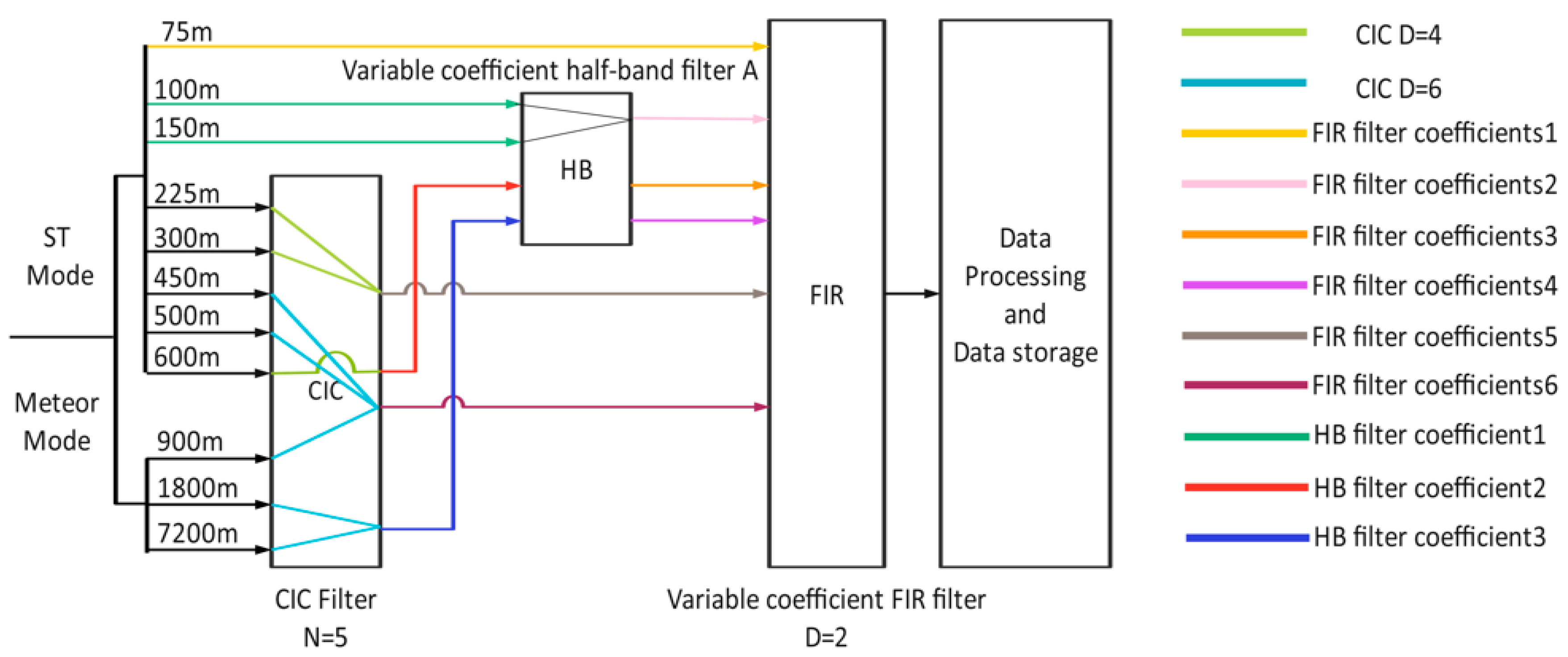
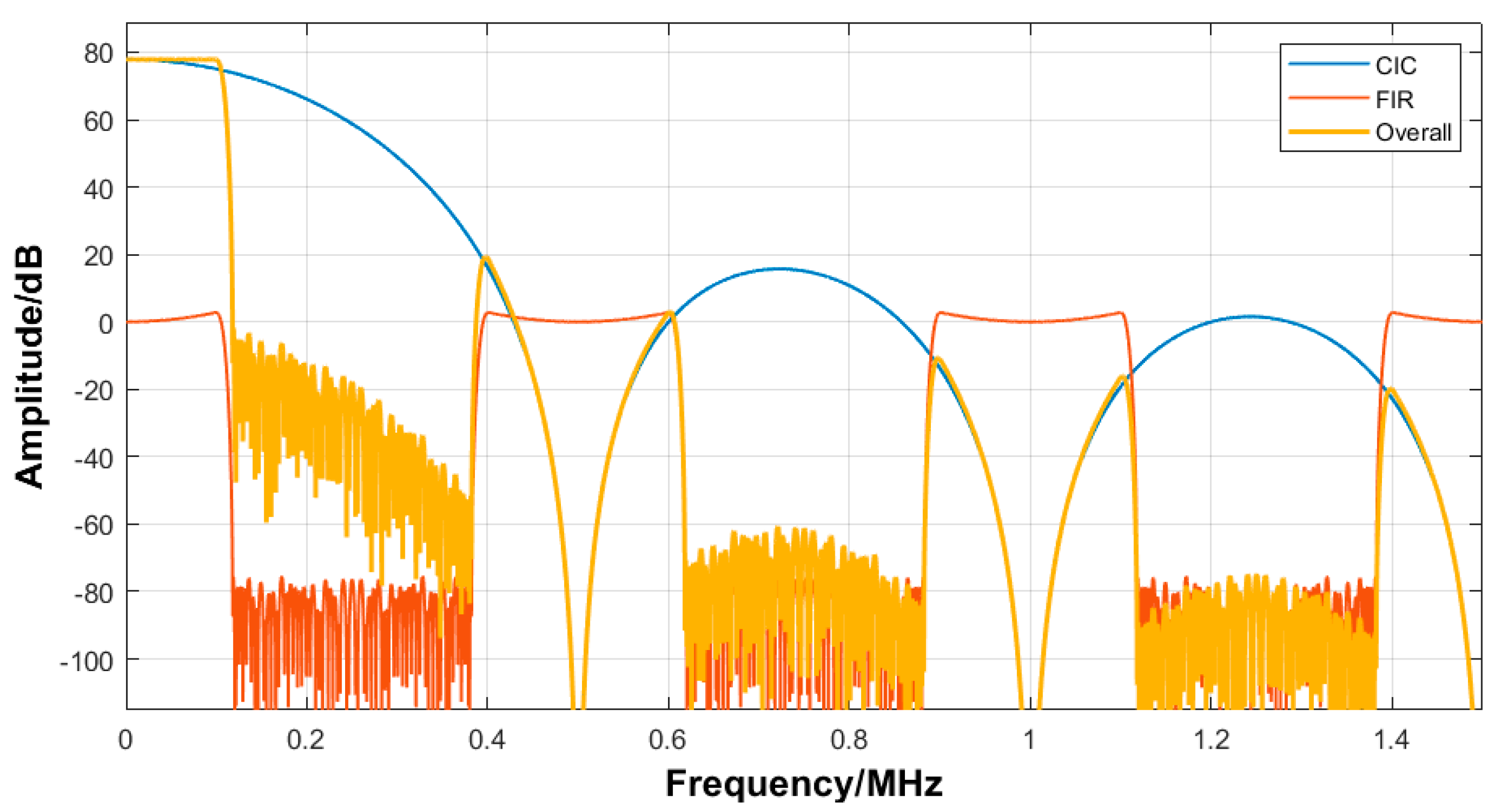
3. FPGA Programming of Reconfigurable Extraction Filter Banks

Figure 4 shows the FPGA programming RTL circuit diagram of the reconfigurable extraction filter bank. The top-level module instantiates the CIC module, half-band filter module, FIR filter module, and the corresponding config module. In the settings of the CIC module, the filter mode is set to extraction, with a cascade number of 5, and the extraction multiple can be dynamically configured through the CIC_config module. The half-band filter and FIR filter can select and switch the pre-calculated and imported filter coefficients through their respective config modules.
Figure 5 shows the simulation results of the digital domain signal processing of the reconfigurable design for radar waveforms with different parameters. Figure 5a shows the extraction filtering results for echo signals with pulse widths of 450 m and 500 m. Obviously, the difference can be ignored when using the same cascade extraction filter combination for echo signals with close pulse widths. Figure 5b shows the pulse compression results after extracting and filtering the phase-coded echo signals with pulse widths of 1800 m and 7200 m. The pulse compression waveforms of the two signals are zero-lag, and the waveforms have the “peg-like” characteristics of the autocorrelation of the complementary codes. Apparently, the subsequent pulse compressions are not affected when using the same cascade extraction filter combination for echo signals with multiplicative pulse widths.
The reconfigurable extraction filter bank is implemented using filter IP cores, including the CIC compiler IP core and the FIR compiler IP core. Table 3 shows the hardware resource consumption after synthesis of the extractor filter bank implemented using the filter IP cores without filter multiplexing and dynamically reconfiguring, with filter multiplexing only, and with filter multiplexing and dynamically reconfiguring. The design of no filter multiplexing and dynamic reconfiguring consumes the most hardware resources. The filter bank implemented with filter multiplexing only consumes the middle of the hardware resources, and the lowest DSP usage is among the three. The filter multiplexing and dynamic reconfiguring method we proposed is slightly higher than the second method in terms of DSP usage and the least in other consumed hardware resources. Taken together, the filter multiplexing and dynamic reconfiguring method is the most optimized design for a filter bank.

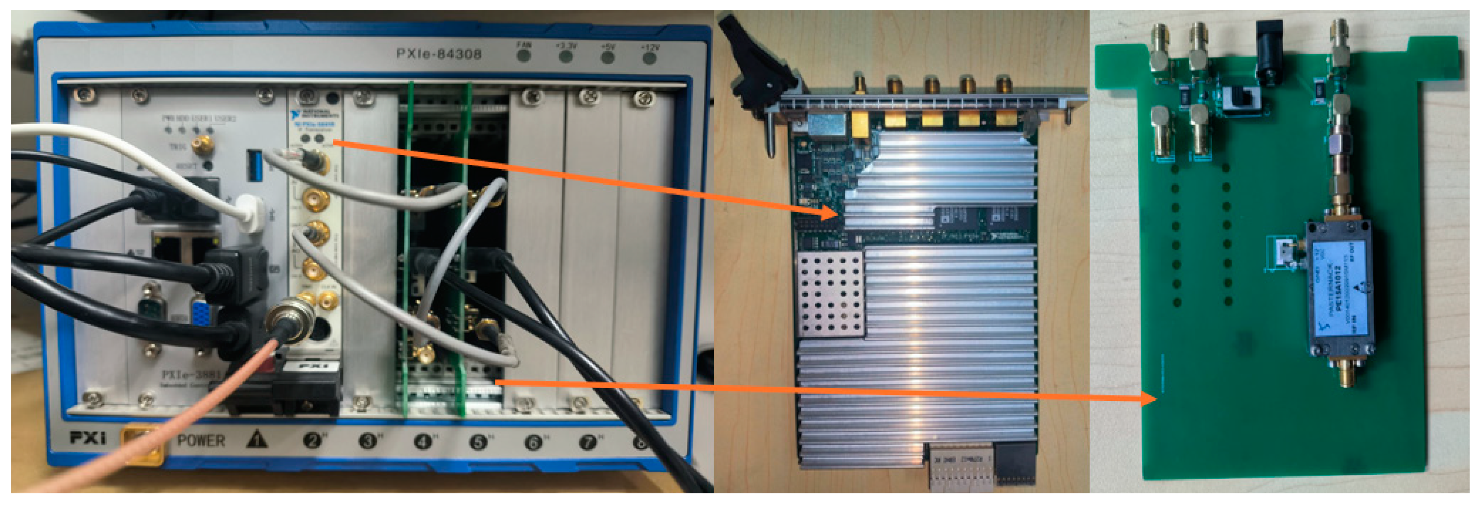
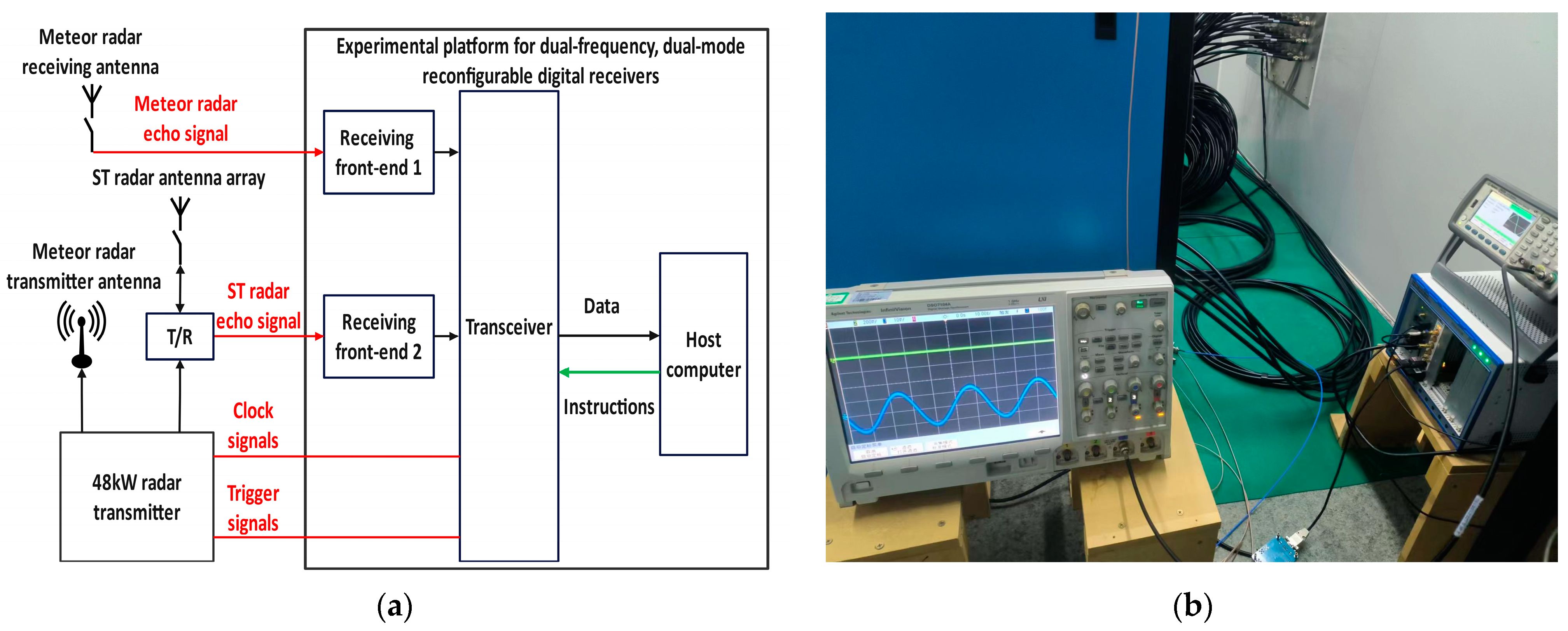
4. Receiver Experimental Platform and Test

We carried out the design and development of a digital receiver parallelly in hardware and software and built a two-channel, dual-frequency, dual-mode reconfigurable digital receiver experimental platform, with one receiver channel configured for ST detection mode and one receiver channel configured for meteor detection mode (shown in Figure 6). The NI-5641R transceiver is in the middle, and the broadband receiver’s front end is on the right.
From 17 January to 22 January 2024, we conducted the receiver field experiment using the 48 kW dual-frequency transmitter, ST radar antenna array, and meteor radar antenna array at the Langfang Site. The experiment parameters are shown in Table 4.
The schematic diagram of the field experiment system and the physical connections during equipment testing are shown in Figure 7.

5. Analysis of Test Results

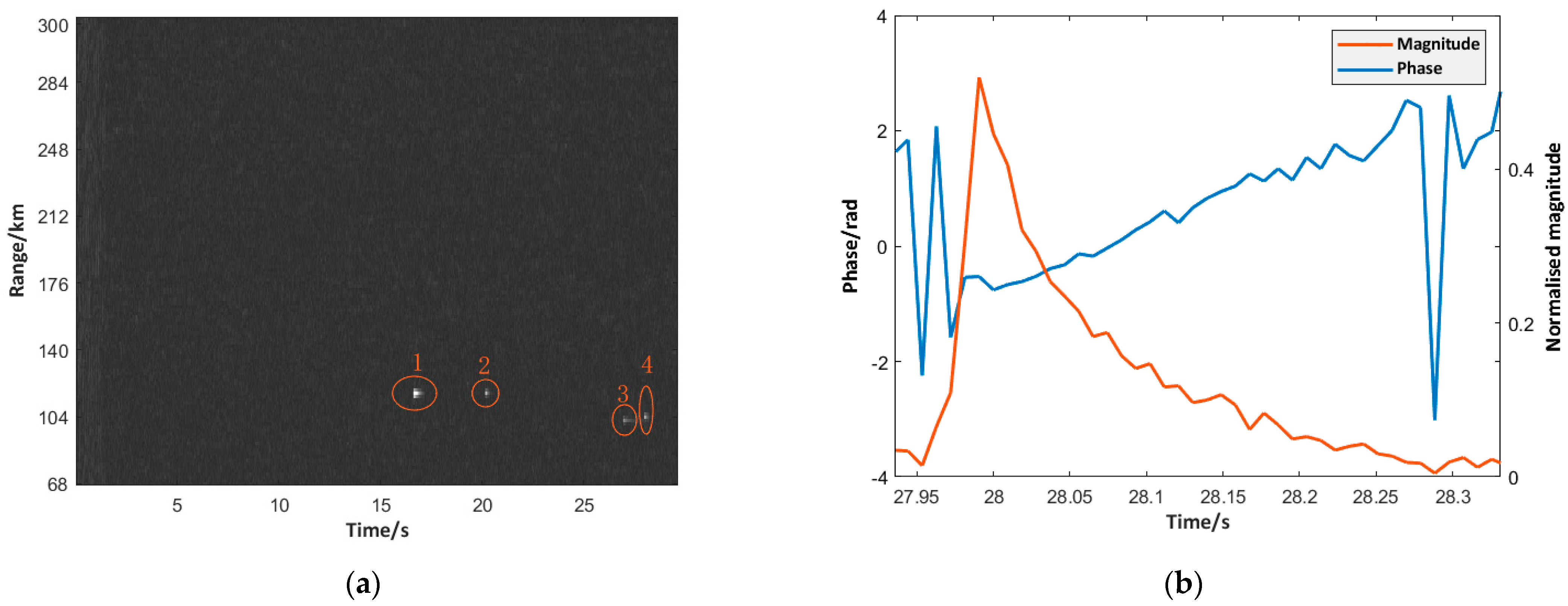
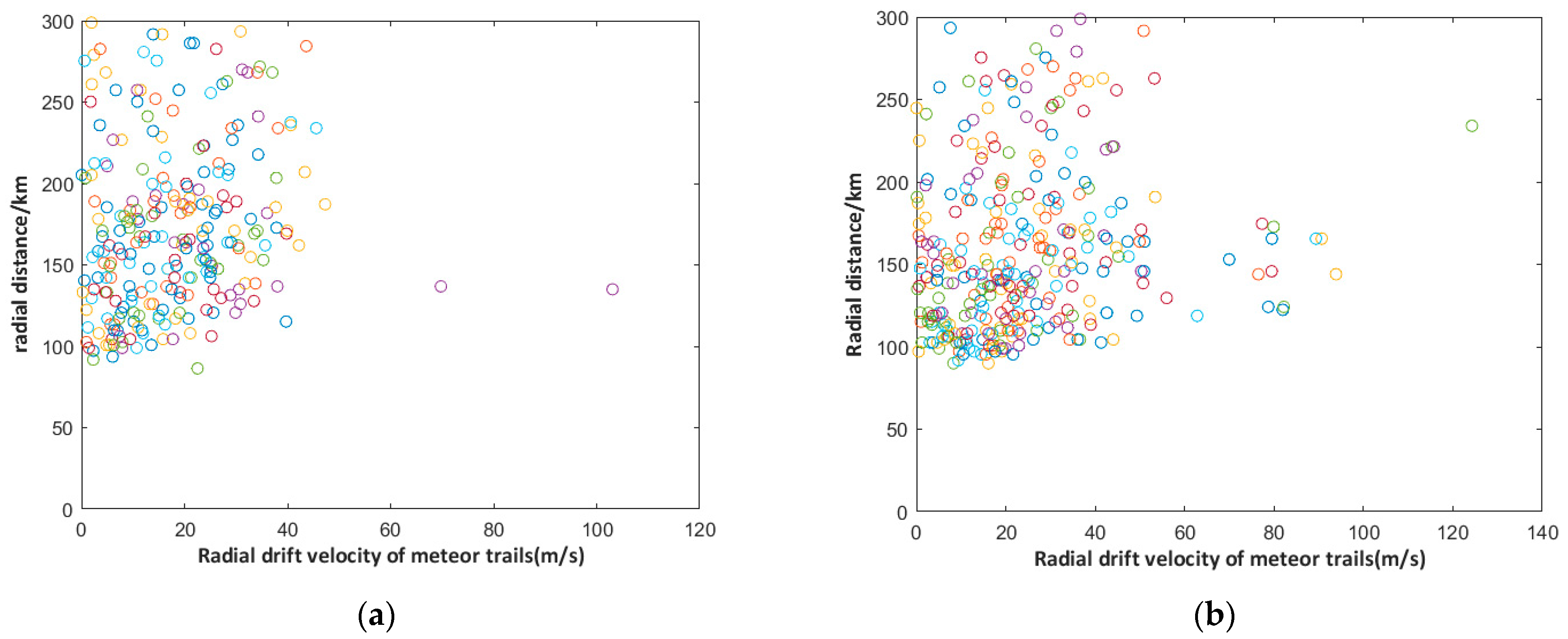
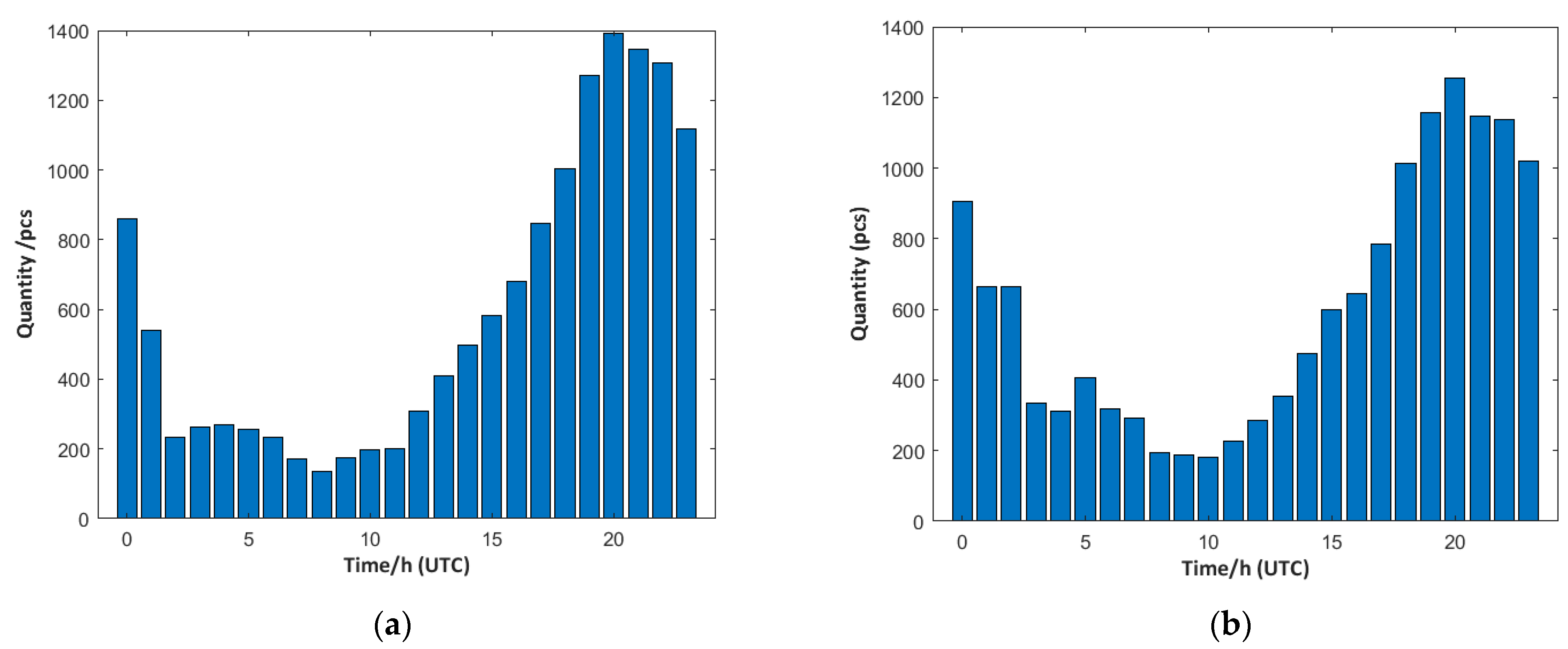
5.1. Meteor Model Detection Results

We performed two meteor detection experiments with excitation signals of an operating frequency of 35.0 MHz and 4-bit complementary code, using pulse widths of 1800 m and 7200 m. The results of the detection experiments are shown in Figure 8 and Figure 9, respectively. Figure 8a and Figure 9a show the 2D distance–time plot of the radar echo signals for 30 s. Four meteor echo signals are detected in Figure 8a, and three meteor echo signals are detected in Figure 9a. Figure 8b shows the amplitude and phase results of the meteor echoes labeled 4, which have the typical Fresnel oscillation characteristics of meteor remnant echoes [26]. Figure 9b shows the amplitude and phase results of the meteor echoes labeled 7. Its Fresnel oscillatory waveform is quite different from the characteristic Fresnel oscillatory waveform of low-density meteor echoes, and its amplitude tends to stabilize after rising to the maximum value and continues to decline for a certain period of time; it has the characteristics of Fresnel oscillatory waveform when it is declining, which is likely to be the splitting of the meteors in the course of their flights. The inverse calculated parameters of the first six meteor trails are shown in Table 5.
Figure 10 shows the radial distance and radial drift velocity distribution of the meteor remnant echoes within 1 h. The meteor echoes are distributed in the radial distance of 70 km to 300 km. Echo numbers decrease with increasing distance. The radial drift velocities are basically less than 100 m/s. These characteristics are consistent with the results of other meteor radars. The receiver detects more meteor trails using an excitation signal of 7200 m pulse width in the same time interval (329 meteor echoes for the 7200 m pulse width and 252 for the 1800 m pulse width), i.e., the energy of the emitted signal is positively correlated with the number of meteor echoes, which is in line with theoretical expectations.
Figure 11 shows the time-dependent distribution of the number of meteors detected by the meteor detection mode on 21 and 22 January 2024, when the transmitted signal pulse width was 7.2 km. It can be seen that the trend of the number of meteors over time is consistent over the two days. This trend is consistent with the time-dependent distribution of the number of meteors over Langfang [27], which further verifies the ability of the meteor detection mode to make continuous observations and the reliability of the data.

5.2. ST Mode Detection Results

ST detection experiments were carried out using an operating frequency of 53.8 MHz and a mono-pulse excitation signal (pulse width of 600 m). Figure 12 shows the five-beam 20 s radar echoes and the power spectrums. Figure 12a shows a two-dimensional distance–time plot of the radar echoes in the altitude range of 1.2 km to 18 km for the five beams (east, west, vertical, south, and north). Significant atmospheric turbulence echoes are detected mainly from the altitude of 1.2 km to 5.4 km. Stronger aircraft clutter signals appear over the altitudes of 6 km, as shown in the frame.
The five-beam radar echo power spectra from 1.2 km to 5.4 km altitude are shown in Figure 12b. The echo Doppler shifts of the east and west beams are basically symmetrical with opposite directions, and the radial wind speeds are about 4.5 m/s near the 1.2 km altitude and 21.4 m/s near 4 km altitude. The echo-Doppler shifts of the south and north beams exhibit the same symmetries as those of the east and west beams, with radial wind speeds of 8.2 m/s near 1.2 km altitude, 24.6 m/s near 2 km altitude, 4.9 m/s near 4 km altitude, and 4.9 m/s near 4 km altitude. The vertical-beam echo Doppler shifts are all around zero. The above radar echo power spectral characteristics are consistent with other ST radar observations.

6. Conclusions

A new type of dual-frequency, dual-mode reconfigurable digital receiver is proposed based on a generic hardware platform that includes a high-bandwidth RF front-end, high-speed data acquisition, and real-time signal processing. By utilizing dynamically reconfigurable technology with FPGA in the digital domain, it achieves adjustments of center frequency and bandwidth for digital intermediate frequency signals in different observation modes, matched filtering for echo signals of varying pulse widths, and coherent accumulation and pulse compression for various radar waveforms. Experimental results from a two-channel, dual-frequency, dual-mode reconfigurable digital receiver experimental platform conducted at the Langfang site demonstrate that our designed receiver successfully processed meteor trail echo signals with 35.0 MHz, 4-bit complementary code, and 1800 m and 7200 m excitation signals, as well as ST echo signal detection with a 53.8 MHz, 600 m pulse width single-pulse excitation signal.
The dual-frequency, dual-mode reconfigurable digital receiver proposed in this paper provides a highly flexible and versatile technical solution for a new dual-frequency atmospheric radar system, which can be applied to a new generation of multifunctional integrated radar systems, such as dual-frequency ST-meteor radar. To be more concise, the advantages of the proposed dual-frequency, dual-mode reconfigurable digital receiver include the following:
(1)
The processing of RF signals is simplified compared to traditional receivers. Due to the reduced use of analog components, the cost per channel and the physical size of the channel are reduced, and the receiver can be made smaller.
(2)
Direct RF sampling allows more signal processing functions to be implemented in the digital domain, such as digital filtering, demodulation, etc., improving flexibility and programmability.
This study has important scientific significance and engineering application value for promoting the technical research of the new generation of autonomous digital radar systems and enhancing the autonomous detection and research capability of the atmospheric environment. It will further develop the dual-frequency, dual-mode reconfigurable six-channel radio-atmospheric radar digital receiver and carry out the near-ground 20 km and 70–100 km atmospheric horizontal wind field detection test and signal processing.

Author Contributions

Conceptualization, Z.Z., Q.X. and X.H.; methodology, Z.Z., Q.X. and X.H.; software, Z.Z.; validation, Z.Z., Q.X. and Y.W.; formal analysis, Z.Z., Q.X. and B.C.; resources, M.Z.; data curation, Z.Z. and Y.W.; writing—original draft preparation, Z.Z.; writing—review and editing, Z.Z., Q.X., B.C. and J.Y.; funding acquisition, Q.X. and J.Y. All authors have read and agreed to the published version of the manuscript.

Funding

This research was funded by the National Natural Science Foundation of China (Grant numbers 12241101, 42174192, and 11872128), the Strategic Priority Research Program of the Chinese Academy of Sciences (Grant number XDA17010302), and the “Climbing Plan” of the National Space Science Centre, Chinese Academy of Sciences. The APC was funded by the National Space Science Center, Chinese Academy of Sciences.

Data Availability Statement

The data are not publicly available due to the laboratory policies or confidentiality agreements.

Conflicts of Interest

The authors declare no conflicts of interest.

References

  1. Cai, B. Researches on MLT Meteor Wind Techniques and Observations of Solar Activities with MF Radar; University of Chinese Academy of Sciences (National Space Science Centre of Chinese Academy of Sciences): Beijing, China, 2021. [Google Scholar] [CrossRef]
  2. Wang, Z.; Xiao, C.; Hu, X.; Yang, J.; Cheng, X.; Xu, Q.; Xiao, L.; Wu, X. Short-Period Variation of the Activity of Atmospheric Turbulence in the MLT Region over Langfang. Atmosphere 2023, 14, 1045. [Google Scholar] [CrossRef]
  3. Wang, J.; Yi, W.; Wu, J.; Chen, T.; Xue, X.; Zeng, J.; Vincent, R.A.; Reid, I.M.; Batista, P.P.; Buriti, R.A.; et al. Coordinated observations of migrating tides by multiple meteor radars in the equatorial mesosphere and lower thermosphere. J. Geophys. Res.-Space Phys. 2022, 127, e2022JA030678. [Google Scholar] [CrossRef]
  4. Chen, Z.; Tian, Y.; Wang, Y.; Bi, Y.; Wu, X.; Huo, J.; Pan, L.; Wang, Y.; Lv, D. Turbulence parameters measured by the Beijing mesosphere-stratosphere-troposphere radar in the troposphere and lower stratosphere with three models: Comparison and analyses. Atmos. Meas. Tech. 2022, 15, 4785–4800. [Google Scholar] [CrossRef]
  5. Sun, R.; Gu, S.-Y.; Dou, X.; Wei, Y.; Qin, Y.; Yang, Z. Decadal Quasi-2-Day Wave Observations in the Equatorial Mesopause Region by a Meteor Radar over Kototabang (0.2° S, 100.3° E) and TIMED/TIDI and Comparison with Quasi-2-Day Wave Observations at Mid-Latitudes. Remote Sens. 2023, 15, 1122. [Google Scholar] [CrossRef]
  6. Pedatella, N.M. Scientific motivations and future directions of whole atmosphere modeling. Front. Astron. Space Sci. 2022, 9, 957007. [Google Scholar] [CrossRef]
  7. Vincent, R.A.; Kovalam, S.; Reid, I.M.; Murphy, D.J.; Klekociuk, A. Southern hemisphere stratospheric warmings and coupling to the Mesosphere-Lower thermosphere. J. Geophys. Res.-Atmos. 2022, 127, e2022JD036558. [Google Scholar] [CrossRef]
  8. Cervera, M.A.; Reid, I.M.J.R.S. Comparison of simultaneous wind measurements using collocated VHF meteor radar and MF spaced antenna radar systems. Radio Sci. 1995, 30, 1245–1261. [Google Scholar] [CrossRef]
  9. Valentic, T.A.; Avery, J.P.; Avery, S.K.; Cervera, M.A.; Elford, W.G.; Vincent, R.A.; Reid, I.M. A comparison of meteor radar systems at Buckland Park. Radio Sci. 1996, 31, 1313–1329. [Google Scholar] [CrossRef]
  10. Reid, I.M.; McIntosh, D.L.; Murphy, D.J.; Vincent, R.A. Mesospheric radar wind comparisons at high and middle southern latitudes. Earth Planets Space 2018, 70, 84. [Google Scholar] [CrossRef]
  11. Hocking, W.K.; Röttger, J.; Palmer, R.D.; Sato, T.; Chilson, P.B. Atmospheric Radar: Application and Science of MST Radars in the Earth’s Mesosphere, Stratosphere, Troposphere, and Weakly Ionized Regions; Cambridge University Press: Cambridge, UK, 2017. [Google Scholar]
  12. Holdsworth, D.A.; Reid, I.M. The Buckland Park meteor radar-description and initial results. In Proceedings of the “Workshop on Applications of Radio Science”, Leura, Australia, 20–22 February 2002. [Google Scholar]
  13. McKinley, D.W.R. Meteor Science and Engineering; McGraw-Hill: New York, NY, USA, 1961. [Google Scholar]
  14. Zhang, Z.M.; Xu, Q.C.; Hu, X.; Zhang, Q.; Cai, B.; Zhao, M.L. High-power pulsed atmospheric radar transmit power measurements. Foreign Electron. Meas. Technol. 2022, 41, 7–11. [Google Scholar]
  15. Zhang, Z.; Shi, J.; Wen, F. Phase Compensation-Based 2D-DOA Estimation for EMVS-MIMO Radar. IEEE Trans. Aerosp. Electron. Syst. 2024, 60, 1299–1308. [Google Scholar] [CrossRef]
  16. Lan, L.; Rosamilia, M.; Aubry, A.; De Maio, A.; Liao, G. FDA-MIMO Transmitter and Receiver Optimization. IEEE Trans. Signal Process. 2024, 72, 1576–1589. [Google Scholar] [CrossRef]
  17. Vipin, K.; Fahmy, S.A. Mapping Adaptive Hardware Systems with partial Reconfiguration using CoPR for Zynq. In Proceedings of the 2015 NASA/ESA Conference on Adaptive Hardware and Systems (AHS), Montreal, QC, Canada, 15–18 June 2015; pp. 1–8. [Google Scholar]
  18. Shang, Z.; Xu, K.; Liu, Y.; Wu, Z.; Lu, G.; Zhang, Y.; Zhang, L.; Su, Y.; Chen, Y.; Yan, F. A broadband solar radio dynamic spectrometer working in the millimeter-wave band. Astrophys. J. Suppl. Ser. 2022, 258, 2. [Google Scholar] [CrossRef]
  19. Yan, F.B.; Liu, Y.; Xu, K.; Shang, Z.Q.; Su, Y.R.; Lu, G.; Chen, Y.; Wu, Z. A broadband digital receiving system with large dynamic range for solar radio observation. Res. Astron. Astrophys. 2020, 20, 156. [Google Scholar] [CrossRef]
  20. Ge, J.; Fok, M.P. Reconfigurable RF multiband filter with widely tunable passbands based on cascaded optical interferometric filters. J. Light. Technol. 2018, 36, 2933–2940. [Google Scholar] [CrossRef]
  21. Mittal, G.; Pathak, N.P. Techniques of Reconfigurable Bandpass Filter for Realization of Adaptable RF System and Proposed Methodology. In Proceedings of the 2017 14th IEEE India Council International Conference, Roorkee, India, 15–17 December 2017. [Google Scholar]
  22. Liu, X.; Yan, X.X.; Wang, Z.K.; Deng, Q.X. Design and FPGA implementation of a reconfigurable digital down converter for wideband applications. IEEE Trans. Very Large Scale Integr. (Vlsi) Syst. 2017, 25, 3548–3552. [Google Scholar] [CrossRef]
  23. Nguyen, N.H.; Khan, S.A.; Kim, C.H.; Kim, J.M. A high-performance, resource-efficient, reconfigurable parallel-pipelined FFT processor for FPGA platforms. Microprocess. Microsyst. 2018, 60, 96–106. [Google Scholar] [CrossRef]
  24. Latiri, A.; Joet, L.; Desgreys, P.; Loumeau, P. A reconfigurable RF sampling receiver for multistandard applications. Comptes Rendus Phys. 2006, 7, 785–793. [Google Scholar] [CrossRef]
  25. Wang, Q.; Wu, Y.; Qi, Y.; Wang, W. A reconfigurable wireless superheterodyne receiver for multi-standard communication systems. Int. J. Electron. 2023, 110, 882–897. [Google Scholar] [CrossRef]
  26. Ceplecha, Z.; Borovička, J.; Elford, W.G.; ReVelle, D.O.; Hawkes, R.L.; Porubčan, V.; Šimek, M. Meteor Phenomena and Bodies. Space Sci. Rev. 1998, 84, 327–471. [Google Scholar] [CrossRef]
  27. Tian, C.X. Researches and Observations of Gravity Wave Activities with Meteor Radar in 40° N China; University of Chinese Academy of Sciences (National Space Science Centre of Chinese Academy of Sciences): Beijing, China, 2021. [Google Scholar] [CrossRef]
Figure 1. Overall design of dual-frequency, dual-mode reconfigurable digital receivers.
Electronics 13 01879 g001
Figure 2. Schematic diagram of filter channels and extraction multiplier.
Electronics 13 01879 g002
Figure 3. Frequency response of CIC and FIR cascade filters with 12× extraction rate and 0.1 MHz passband width.
Electronics 13 01879 g003
Figure 4. RTL circuit design of reconfigurable filter bank (partial).
Electronics 13 01879 g004
Figure 5. Simulation results of signal processing of radar waveforms with different parameters by reconfigurable design (integral): (a) results of 450 m and 500 m echo signals processed by reconfigurable extraction filter bank; (b) pulse compression results after extraction and filtering of 1800 m and 7200 m echo signals.
Electronics 13 01879 g005
Figure 6. Receiver experimental platform physical diagram.
Electronics 13 01879 g006
Figure 7. Equipment connection schematic and physical diagram: (a) schematic diagram of the receiver field experiment; (b) the physical connections during equipment testing.
Electronics 13 01879 g007
Figure 8. Example of a meteor detection mode echo signal (05.31 UT on 18 January 2024, pulse width 1800 m): (a) 2D distance–time plot of the radar echo signals for 30 s; (b) meteor echo amplitude and phase processing results.
Electronics 13 01879 g008
Figure 9. Example of a meteor detection mode echo signal (07.05 UT on 18 January 2024, pulse width 7200 m): (a) 2D distance–time plot of the radar echo signals for 30 s; (b) meteor echo amplitude and phase processing results.
Electronics 13 01879 g009
Figure 10. Distribution of radial distances and radial drift velocities of meteor echoes detected within one hour: (a) distance–velocity distribution of meteors in 1 h using 1800 m pulse width (from 05.00 h UT on 18 January 2024 to 06.00 h UT on 18 January 2024); (b) distance–velocity distribution of meteors in 1 h using 7200 m pulse width (from 07.00 h UT on 18 January 2024 to 08.00 h UT on 18 January 2024).
Electronics 13 01879 g010
Figure 11. Time-dependent distribution of the number of meteors: (a) on 21 January 2024; (b) on 22 January 2024.
Electronics 13 01879 g011
Figure 12. The five-beam 20 s radar echoes and the power spectrums: (a) 2D distance–time plot of the radar echoes in the altitude range 1.2 km to 18 km for the five beams (east, west, vertical, south and north); (b) the five-beam radar echo power spectra from 1.2 km to 5.4 km altitude.
Electronics 13 01879 g012
Table 1. Receiver reconfigurable parameter design (partial).
ParametricMeteor Detection ModeST Detection Mode
Operating frequency35.0 MHz53.8 MHz
WaveformEncoded WaveformsGaussian monopulse
Number of channels51
Type of codeBarker Code/Complementary CodeNo phase encoding
Code element lengthBarker Code: 2/3/4/5/7/11/13
Complementary Code: 2/4/8/10/16/32
/
Pulse width (m)900/1800/720075/100/150
225/300/450
500/600
Table 2. The features of the three receivers and their advantages and disadvantages.
Multi-Band ParallelSuperheterodyneDirect RF Sampling
Features1. Multiple independent receivers operating in parallel
2. Each handles a specific frequency band
Selected signals down-converted to IF by bandpass filters and mixersRF signals are fed directly into the analog-to-digital converter via the RF front-end
Advantages1. Simultaneous coverage of multiple frequency bands
2. Each frequency band operates independently; partial failure does not affect the whole
1. High-frequency selectivity and sensitivity
2. Reduced reliance on RF high-gain amplifiers
1. Simplified signal processing flow
2. Programmable digital domain signal processing
3. Reduced use of analog components, small size, and low cost
DisadvantagesRequires multiple sets of complete hardware resources, large size, high cost, poor scalabilityRequires local oscillators and multi-stage mixing systems with high complexity and many analog componentsRequires certain ADC performance
Table 3. Hardware resource consumption of filter banks for different implementations.
No Filter Multiplexing and No Dynamic ReconfiguringFilter Multiplexing OnlyFilter Multiplexing and Dynamic Reconfiguring
LUT (pcs)31521182743
LUTRAM (pcs)2155809511
FF (pcs)502018801178
DSP (pcs)271014
IO (pcs)171717
Table 4. Meteor detection mode and ST detection mode experiment parameters.
ParametricMeteor Detection ModeST Detection Mode
Operating frequency35.0 MHz53.8 MHz
Pulse Repetition Frequency (PRF)430 Hz6000 Hz
Transmitting power48 kW48 kW
Gain38 dB38 dB
Number of beams/5 (East, West, Vertical, South, North)
Detection height68.4~300 km1.2~18 km
WaveformEncoded WaveformsGaussian monopulse
Type of codeComplementary code/
Code element length4/
Coherence point16150
Length of experimental sequence30 s/time20 s/time
Number of pulses per test12,900120,000
Pulse width (m)1800/7200600
Table 5. Parameters related to the aftermath of six meteors.
No.Radial Distance/kmTime/s
1117.016.6
2117.020.1
3102.627.0
4106.227.9
591.8−9.12
6164.0−30.62
Disclaimer/Publisher’s Note: The statements, opinions and data contained in all publications are solely those of the individual author(s) and contributor(s) and not of MDPI and/or the editor(s). MDPI and/or the editor(s) disclaim responsibility for any injury to people or property resulting from any ideas, methods, instructions or products referred to in the content.

