1. Introduction
Ideally suited for sixth-generation (6G) mobile communication systems, integrated sensing and communication (ISAC) has gained growing attention due to its enormous potential in overcoming spectrum congestion, saving hardware costs, and enhancing system spectrum efficiency [
1,
2,
3,
4].
A joint design for the coexistence of radar and communication systems to achieve spectrum sharing has previously been used to enable ISAC in the same frequency band but on different devices. In this approach, radar and communication systems exchange side information for obtaining a beneficial cooperation. To this end, opportunistic spectrum sharing might be a directly viable scheme where the communication systems become active only if the spatial and spectral resources are not occupied by the radar [
5]. However, this approach does not allow two systems to work simultaneously. As a step forward, the authors of [
6] designed radar beamformers by taking the zero-forcing criterion, thus eliminating radar interference with communications. More recent beamforming designs exploit optimization tools to realize radar and communication coexistence. In [
7,
8], a radar beamformer and a communication covariance matrix were jointly designed with the aim of optimizing the signal-to-interference-plus-noise ratio (SINR) at the radar receiver under capacity and power constraints on the communication side. In a comparable scenario, efforts were made to robustly maximize radar detection probability in the presence of imperfect channel state information in [
9]. Considering a more realistic scenario with surveillance radars deployed in cluttered environments, the mutual information between the input and output of a communication link [
10] or communication energy efficiency [
11] was optimized under radar performance and power budget constraints, respectively. Although these coexistence system designs seem an effective way to implement ISAC, they might entail extra expenses for hardware and energy, along with augmented system complexity [
12].
To enhance efficiency, an encouraging strategy for enabling ISAC involves the creation of DFRC systems. These systems utilize identical signals for both target detection and user communication concurrently, operating on a unified platform. However, given the constrained resources of DFRC systems, ensuring or enhancing sensing and communication performance simultaneously becomes challenging. Essentially, stringent performance guarantees can only be afforded to one system, while the other system can only achieve a best-effort performance level.
The majority of prior studies [
12,
13,
14,
15,
16,
17,
18] have focused on enhancing radar functionality while accommodating communication constraints through beamforming methodologies, thereby shaping a communication-centric DFRC system. For instance, efforts have been made to minimize errors in beampattern matching while guaranteeing a pre-defined level of SINR for each communication user, as demonstrated in [
12,
13,
14]. Under a similar communication performance constraint, the optimization of the Cramér–Rao bound (CRB) for target estimation was pursued to directly assess sensing capabilities in [
15,
16,
17]. Additionally, joint designs for transmit and receive beamforming were developed in [
18] to maximize the SINR at the radar receiver while meeting spectral efficiency requirements. These communication-centric designs, however, prioritize communication performance over sensing, so radar performance is much worse than it would be without communication functions. In order to ensure better sensing performance, the authors of [
19] designed hybrid beamforming solutions to optimize the weighted sum of the communication spectral efficiency and the radar beampattern matching errors. It is possible to achieve the desired trade-off between communication and radar by adjusting the weight coefficients. Likewise, in [
20], the receive SINR at the radar and multi-user interference were combined into a composite objective function, and the transmit and receive beamformers were designed jointly. Some recent designs tried to optimize the communication performance subject to the beampattern mismatch error constraint [
21,
22], which better preserved the sensing performance. However, these designs [
19,
20,
21,
22] still somewhat weaken the sensing performance compared with a separate radar without communication functions.
To avoid the performance loss of the radar, it is possible to incorporate communication functions into pre-designed radar systems, leading to a radar-centric DFRC system. Towards this goal, some earlier studies have tried to embed communication information into radar signals to achieve dual functionality. For example, by employing waveform diversity and sidelobe control, information sequences were embedded into radar pulses in [
23]. Nevertheless, such information embedding designs cannot utilize the spatial diversity gains of multi-input–multi-output (MIMO). As MIMO radar sensing strongly relies on the transmit covariance of waveforms [
24,
25], some recent works optimized the communication performance under the prescribed transmit covariance constraint for stringent sensing quality assurance. Optimal transmit waveform/beamforming designs were proposed under the instantaneous covariance constraint in [
26] or under the average covariance constraint in [
27]. However, the approaches in [
26,
27] could not be extended to more general MIMO DFRC systems that admit transmissions of multiple data streams for each communication user. In view of this, our previous work [
28] put forth efficient (linear) transmit and receive beamforming designs to aid in maximizing user rates under the prescribed transmission covariance constraint in MIMO DFRC systems.
The beamforming schemes in [
28] can significantly improve the communication (i.e., spectral efficiency) performance of DFRC systems while strictly preserving the radar sensing performance. Yet, such a linear beamforming design cannot effectively eliminate the inter-user interference and interference between radar and communication signals, thereby hindering further improvements in the communication rates. To overcome this limitation, in this paper, we propose to adopt dirty paper coding (DPC) to perform effective interference (pre-)cancellation at the transmitter (i.e., the base station) of downlink communications and address optimal beamforming designs for a DPC-based MIMO DFRC system that detects several targets and communicates with a number of users simultaneously on the same hardware platform.
The key contributions of this work are summarized as follows:
We put forth novel beamforming design approaches to achieve the maximum weighted communication sum rate with specified transmit covariance for a DPC-based MIMO DFRC system.
We reformulate the intended problem and develop a block coordinate descent (BCD) method that calculates transmit and receive beamforming solutions in an alternating manner by leveraging the connection between the weighted sum rate and the weighted minimum mean squared error (MMSE).
With this BCD approach, the optimal receive beamforming design can be obtained in closed form, and the optimal transmit beamforming design can be cast into a quadratic optimization problem defined on a complex Stiefel manifold. Based on the majorization–minimization (MM) approach, an iterative algorithm is then developed to compute the optimal transmit beamforming design by solving a series of orthogonal Procrustes problems (OPPs) that admit closed-form optimal solutions.
The subsequent sections of this paper are structured as follows:
Section 2 delineates the system model. In
Section 3, we introduce a proficient BCD algorithm aimed at attaining a high-performance beamforming configuration.
Section 4 presents simulation outcomes, succeeded by the conclusions outlined in
Section 5.
Notation: Boldface upper- and lowercases stand for matrices and vectors, respectively; , , , , , and signify the transpose, conjugate transpose, inverse, trace, determinant, and Frobenius norm of a matrix, respectively; for a symmetric matrix , signifies that is positive semi-definite; stands for the identity matrix; represents the set of complex matrices; stands for taking the real part of a complex variable, while stands for taking ensemble expectation; represents the complex normal distribution.
2. System Model
We explore a MIMO DFRC setup where a base station (BS) concurrently detects
J distant targets and communicates with
K downlink users on the same hardware platform. We use
Figure 1 to illustrate the setup. The BS is outfitted with
transmitting antennas, while each user possesses
(
) receiving antennas. We use
to represent the channel matrix between the BS and user
k. We assume that the perfect channel state information (CSI) is known both at the transmitting side and the receiving side.
Radar waveforms and communication symbols are precoded into the transmit signal
:
where
encompasses
streams of information, undergoing precoding through the utilization of the communication beamforming matrix
. Here,
is designated as the beamforming matrix for transmitting the (multi-stream) communication symbol vector
to user
k at time
n from the BS. For sensing purposes, a radar signal vector
, comprising
random symbols generated independently [
27], is transmitted concurrently with
, and it undergoes precoding using a radar beamforming matrix
.
It is assumed that the communication symbol vectors of different users are mutually independent, which means that . Additionally, it is also assumed that the overall communication symbol vector is irrelevant to the radar signal vector, i.e., .
2.1. Sensing Performance Guarantee
For the signal model (
1) under consideration, communication beamforming matrix
can be used for the sensing purpose jointly with radar beamforming matrix
, since it is perfectly known at the BS. We denote the overall
beamforming matrix by
. The sensing performance of a MIMO radar is highly related to its transmit beampattern, which depends on the covariance of transmit signals, i.e.,
To better preserve the sensing performance, a desired transmit covariance matrix (
) should be designed in advance according to the specific application requirements [
24]. Then, the transmit covariance is required to match the predetermined
, as given by
By enforcing this transmit covariance constraint on , the sensing performance can be guaranteed. From this constraint, we can observe the importance of introducing radar waveforms precoded by in such a DFRC system. To be specific, if , in other words, only communication symbols are transmitted, the rank of cannot exceed D with . As a result, the prescribed whose rank is larger than D can never be satisfied. With the introduced , the degree of freedom (DoF) of is equal to the number of transmitting antennas, , and any prescribed can be met with an appropriate combination of and .
It is noteworthy that the transmit covariance constraint (
3) essentially imposes a limitation on the power allocation for the transmit beamforming matrix (
). The overall transmit power can be explicitly determined as
under a particular
. In conventional beamforming optimization scenarios, the power allocation restriction might manifest as
, where
denotes the maximum allowable power budget at the BS. In our DFRC system, as the radar always probes signals with the maximal available power, we should always have
. Thus, the transmit power constraint on
can be implicitly incorporated into constraint (
3) for compactness.
2.2. DPC for Multi-User Communications
Although the transmit covariance constraint (
3) strictly preserves the sensing performance, it will, in turn, damage the performance of downlink multi-user communications. Specifically, to zero-force the interference from the other users’ signals and the radar signals, the transmit beamforming matrix (
) should satisfy [
29]
where we have
and
is the block diagonal. Nevertheless, with
in (
3), the term
is fixed for the given channel matrix
and the pre-designed transmit covariance
, making it hard to meet (
4). As a result, the interference cannot be pre-canceled effectively by the linear transmit beamforming design of
.
To further improve the communication performance, we resort to the non-linear precoding technology, i.e., DPC, to eliminate the interference arising from the other users’ signals and the radar signals at the transmitter. From an information-theoretic perspective, if the transmitter is aware of the interference, the capacity of an additive white Gaussian noise (AWGN) channel in the presence of the interference is equal to that of an AWGN channel without interference [
30]. The key to this interesting result is the use of DPC, which can effectively pre-cancel all the known mutual interference among the multiple data streams. Based on the principles of DPC, we can serially encode first the radar signals and then the communication users’ signals. After encoding radar signal
, the signal of each user is encoded in reverse order, i.e., from the
K-th user to the first user. In this way, when performing DPC for the
k-th user’s signal
, the signals
and
have already been encoded, while
have not. Thus, the interference from the radar signals and users
is known, and the interference from users
is unknown at the transmitter. The signal received by user
k is written as
where
represents AWGN with zero mean and covariance matrix
. The noise is assumed to be irrelevant to radar and communication signals. With the help of DPC, the known interference, i.e., the third and fourth terms on the right-hand side (RHS) of (
5), can be eliminated at the receiver of user
k. Thus, the effective received signal at user
k consists of only the desired signal and the effective noise, as given by
By using a linear reception beamforming matrix labeled
, the signal approximation at user
k can be represented as
To evaluate the performance of downlink communications, the weighted sum rate is selected as the performance metric. For the DPC-based MIMO DFRC system under consideration, the weighted sum rate can be denoted by
where weight
is utilized to indicate the priority of user
k in our system. Based on the signal model (
6), the achievable rate (
) of
k-th user can be calculated as
Our goal is to design the
and
that achieve the maximum weighted sum rate in (
8) subject to the transmit covariance constraint (
3) to guarantee the sensing performance preferentially.
3. Proposed Beamforming Design
Based on objective (
8) and constraint (
3), we wish to solve the following optimization problem:
Note that as explained in
Section 2, the transmit power budget constraint has been incorporated into
in (10b). Clearly, problem (10) exhibits non-convexity arising from its non-convex objective and quadratic equality constraint. In what follows, we put forth a BCD-type algorithm to solve this problem.
3.1. Problem Reformulation
To facilitate an efficient solver for (10), we transform the non-convex objective (10b) into an equivalent form based on the relation between the weighted sum rate and the weighted MMSE. This is performed by first using
to collect all receive beamforming matrices of all downlink users. The MSE matrix of
k-th user can be written as
The original problem can then be reformulated into a matrix weighted sum–MSE problem:
where we introduce the weight matrices
,
, as auxiliary optimization variables. It is observed that (12) consists of variables
,
, and
. The equivalence between problems (10) and (12) can be established by the introduced lemma [
31,
32].
Lemma 1. The optimal transmit beamforming solutions () to the problems in (10) and (12) coincide. Furthermore, stands as a stationary point solution for (10) only if it constitutes a stationary point solution for (12).
Based on Lemma 1, a BCD-type method can be readily developed as follows.
3.2. BCD Method
Since the optimization variables in (12) are composed of , , and , we may optimize them in an alternating manner. The whole procedure includes the following steps.
(1) Optimizing with fixed and
Solving
for (12) is equivalent to minimizing
. Here, the positive semi-definite
only serves as a coefficient matrix. Hence, minimizing
is equivalent to minimizing
. Given
in (
11), it is clear that the MMSE receive beamformer should be adopted by user
k, i.e.,
(2) Optimizing with fixed and
By substituting (
13) into (
11), the MSE matrix of user
k now becomes
With fixed
and
, we have an unconstrained convex problem regarding
, to which the optimal solution is
This is obtained based on the first-order optimality condition of
.
(3) Optimizing with fixed and
The most challenging phase of the suggested BCD strategy to tackle (12) involves the optimization of the transmit beamforming matrix,
. The subproblem for
can be written as
Obviously, (16) is a non-convex problem stemming from the quadratic equality constraint in (16b). Unlike (
13) and (
15), a closed-form optimal solution cannot be derived for (16). In what follows, we put forward an iterative algorithm to resolve this problem efficiently.
3.3. Optimization of Transmit Beamforming Matrix
To solve (16), we first transform it into a quadratic problem defined on a complex Stiefel manifold. There is indeed inherent orthogonality among the transmit beamforming vectors due to the transmit covariance constraint in (16b). To see it, Cholesky decomposition is applied to
, i.e.,
where
is a lower triangular matrix.
We substitute (
17) into (16b) and then rewrite (16b) as
With
and
for brevity of notation, we can equivalently rewrite (16) as
Given
, we can obtain
and
. Additionally, it is observed that objective (19a) is only a function of
and that
only contributes to meet constraint (19b). This is because the radar signals would not interfere with communication signals due to the use of DPC at the transmitter. For this reason, we can replace constraint (19b) with
by taking
as the optimization variable, instead of
.
We can also perform the following rearrangements on (19a)
where
is based on
and
is obtained through polynomial rearrangements of the first term in (20c).
We define
and
in (20); we can then equivalently rewrite (16) as
Notice that (21) is a quadratic problem defined on a complex Stiefel manifold, according to the non-convex orthogonality constraint in (21b). Although (21) is non-convex, an MM optimization approach can be employed to solve it iteratively by tackling a series of OPPs, with a closed-form solution per iteration.
To be specific, each iteration of the MM approach involves two procedures [
33]: (i) (majorization) finding a surrogate function that provides a local upper bound to the objective function and (ii) (minimization) minimizing the surrogate function. By selecting an appropriate surrogate function, solving the original difficult problem can be replaced by solving a sequence of approximate problems that are easy to deal with. In the context of this paper, we can find a linear surrogate function for (21a) at each iteration of MM and transform each approximate problem per iteration into an OPP, resulting in a closed-form, globally optimal solution. The details are as follows.
First, we construct the surrogate function as follows: By denoting the current local point in the t-th iteration as and defining (21a) as , we have the following proposition.
Proposition 1. is upper-bounded by a linear function at , as given bywhere and is the largest eigenvalue of . We use “” to represent a constant term. Additionally, the equality is achieved at . Proof. Since the second term of
, i.e.,
, is linear, we only need to construct a surrogate function for the first term of
, i.e.,
. Since
is convex with respect to
, it cannot be readily upper-bounded by using its first-order Taylor’s expansion. Thus, we perform the following reformulations:
where
is based on
and
as implied by (21b).
Since
is now a negative semi-definite matrix, the term
is concave over
. Thus, it is upper-bounded by its first-order Taylor’s expansion, as given by
where the equality is taken at
.
Then, we have
where
is based on (23) and
holds due to (
24). The proposition then readily follows. □
Based on Proposition 1, problem (21) is transformed into an approximate problem at point
in the
t-th iteration with the objective replaced by
, i.e.,
For (26a), we drop the constant term and perform the following rearrangements:
By defining
and turning minimization into maximization, problem (26) can be rewritten as
Interestingly, while problem (28) remains non-convex, it has an equivalent OPP reformulation as affirmed by the lemma below.
Lemma 2. Problem (28) can be equivalently transformed into the following OPP: Proof. Notice that
In (
30),
is fixed in each iteration, and
is thus a constant. Additionally, we also have
by constraint (29b). It then readily follows that the majorization of
is equivalent to the minimization of
. □
Referring to Proposition 7 of [
34], problem (29) indeed has a closed-form, globally optimal solution. To be specific, we perform SVD on matrix
, i.e.,
, where
collects the eigenvalues of
along its diagonal in descending order. Then, we can achieve the unique optimal solution for (29), as given by
where
consists of the first
D columns of
.
Note that the optimal
is also the optimal solution for (26) based on the equivalence between (26) and (29). Having obtained the optimal
for (26), at the
t-th iteration, we can update the current local point as
and repeat the process.
The convergence of the proposed MM algorithm can be guaranteed, since the whole procedure generates a sequence
that monotonically decreases the objective value of
in (21a), i.e.,
and
is lower-bounded over a compact feasible set. Upon convergence, the optimal radar beamforming matrix,
, should be projected into the null space of
by constraint (19b). Based on the SVD of
, it can be readily inferred that
where
consists of the last
column vectors of
. Then, we have
, which, in turn, leads to
. As the
obtained by the MM method is a stationary point solution for problem (21) [
35],
is also a stationary point for the original subproblem (16) by the equivalence between the problems in (16) and (21).
3.4. Analysis of Overall Algorithm
The overall BCD procedure for solving (12) is formally described in Algorithm 1.
| Algorithm 1 The proposed BCD algorithm for solving (12). |
- 1:
Initialize . - 2:
Repeat - 3:
Given , obtain by ( 13), . - 4:
Given and , obtain by ( 15), . - 5:
Given and , obtain using MM approach and update . - 6:
Until convergence.
|
The convergence of Algorithm 1 can be guaranteed, since each iteration decreases objective (12a) with a lower bound resulting from (12b). Additionally, objective (12a) is differentiable and the constraint set that can be decoupled among
,
, and
with independent subproblems in (12). It readily follows from [
36] that BCD-based Algorithm 1 certainly converges to at least a stationary point
of problem (12). By the equivalence between problems (10) and (12) established in Lemma 2, we immediately deduce that the corresponding
at point
is also a stationary point for the original problem (10).
With the optimal transmit beamforming matrix
obtained by Algorithm 1, to achieve the corresponding maximum rate at user
k, the optimal receive beamforming matrix should adopt the classic MMSE form, as given by (cf. (
13))
For the subproblem at each step of the proposed BCD algorithm, we either obtain a closed-form solution (cf. (
13) or (
15)) or iteratively solve it by using the MM method with a closed-form solution available per iteration. This leads to fast convergence to a high-quality beamforming design, as also verified numerically in
Section 4.
The complexity of the proposed BCD is dominated by the optimization of based on the MM method, i.e., Step 5 in Algorithm 1. Each iteration of MM for computing the optimal only involves an SVD of and matrix multiplications. Hence, the per-iteration complexity of MM is . Let us suppose that the numbers of iterations before convergence of the MM method and the overall BCD are and , respectively. The overall complexity of BCD-based Algorithm 1 is . As a result, BCD-based Algorithm 1 has (low) polynomial-time computational complexity.
One limitation of the proposed approach is that the implementation of the DPC scheme at the transmitter could increase the complexity of multi-user MIMO DFRC systems to some extent. Additionally, compared with the previous work [
28], which admits a closed-form solution for globally optimal transmit beamforming, we adopt the MM method to optimize transmit beamforming
iteratively, leading to extra computational complexity.
4. Numerical Results
A Monte Carlo simulation is performed to assess the proposed scheme. Let us suppose that the BS and the communicating users are both equipped with uniform linear arrays with even antenna spacing. The spacing between adjacent antennas is set to half wavelength. By default, there are antennas at the BS. Let us assume that the same number of receiving antennas is used for radar echo signals. Channel fading model , is based on Rayleigh fading; in other words, each element in obeys the standard complex Gaussian distribution . The BS performs full-power transmissions with the total transmit power budget being P, and the transmit signal-to-noise-ratio (SNR) is defined as .
For the purpose of sensing, we suppose that the radar system detects
targets of interest with angles of
,
, and
. We can design the prescribed transmit covariance matrix (
) by solving a classic least-squares problem to minimize the mismatch errors between the designed radar beampattern and the ideal radar beampattern, as in [
24]. The ideal beampattern (
) composed of three main beams with a beam width of
each is given by
The designed radar beampattern is illustrated in
Figure 2 with
.
To compare with “Proposed BCD” solution yielded by Algorithm 1, we introduce the following benchmark schemes:
Dual program [
27]: DPC is also utilized for the sum rate maximization by using the downlink–uplink duality scheme, which can achieve a globally optimal solution. Nevertheless, this scheme only applies to multi-input–single-output (MISO) systems, supporting transmissions of the single data stream to each user. To ensure a fair comparison, when each user possesses multiple receiving antennas, the row with the largest 2-norm in the corresponding channel matrix is selected for implementing this scheme.
Without DPC [
28]: Here, beamforming designs are put forth for MIMO DFRC systems without DPC at the transmitter. A BCD-type method is used to optimize the sum rate of communication users.
Cholesky: The transmission beamforming matrix is designated as
, where
is derived through Cholesky decomposition applied to
, as defined in (
17). It is worth mentioning that
also acts as the starting point in our proposed BCD approach.
Let us suppose that there exist
users, each equipped with
receiving antennas. Unless otherwise specified, it is assumed that each user has the same priority in the system, i.e.,
. The BS transmits
data streams to each user.
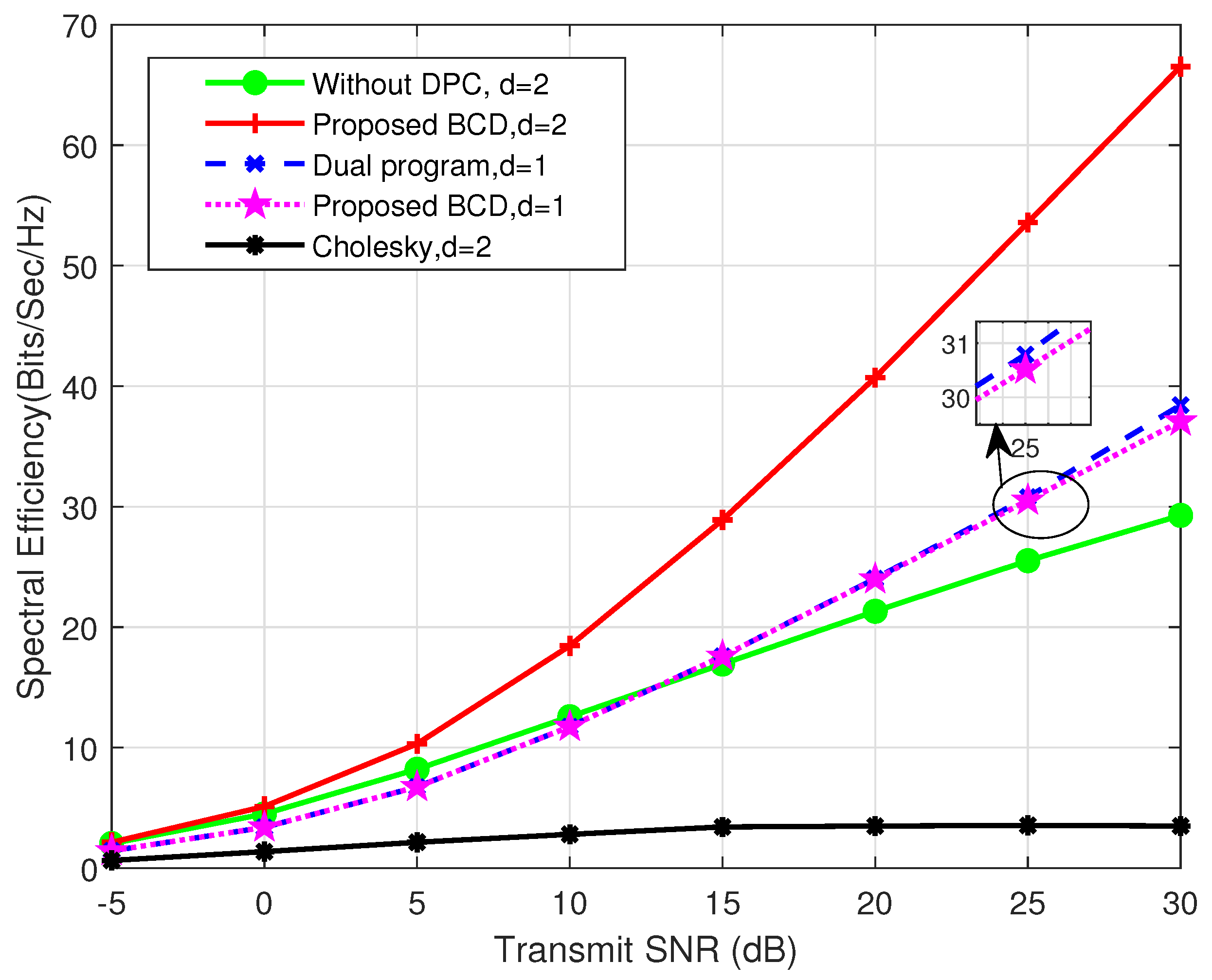
Figure 3 illustrates the spectral efficiency (the achievable sum rate under the unit bandwidth) of various beamforming strategies across different transmit SNRs. The results demonstrate the notable superiority of the proposed BCD scheme over alternative benchmark approaches. To be specific, the proposed design performs much better (e.g., 128% higher spectral efficiency at a 30 dB SNR) than the scheme in [
28] without DPC at the transmitter, especially in a high SNR regime. Since the transmit beamforming matrix is confined by the transmit covariance constraint in (
3), the interference from the other users’ signals and the radar signals cannot be zero-forced effectively if DPC is not performed at the transmitter, which then limits the achievable data rate of each user.
On the contrary, utilizing DPC at the transmitter enables interference cancellation even within the confines of the transmit covariance constraint, resulting in significantly enhanced overall spectral efficiency. In comparison with the “dual program”, which only accommodates data stream for each user, our proposed BCD solution can achieve a minimum of 73% higher spectral efficiency. This validates the efficacy of our approach in leveraging MIMO transmissions to augment communication capacity through the joint design of transmit and receive beamforming. Intriguingly, when we execute the proposed algorithm with , the attained spectral efficiency closely matches the globally optimal performance obtained by the “dual program”, suggesting that our scheme may offer a near-optimal beamforming solution in multi-user scenarios. Moreover, the notable contrast in performance, exemplified by approximately a 20-fold increase in spectral efficiency at a 30 dB SNR, between our suggested BCD approach and Cholesky decomposition highlights the considerable advantages stemming from our BCD iterations.
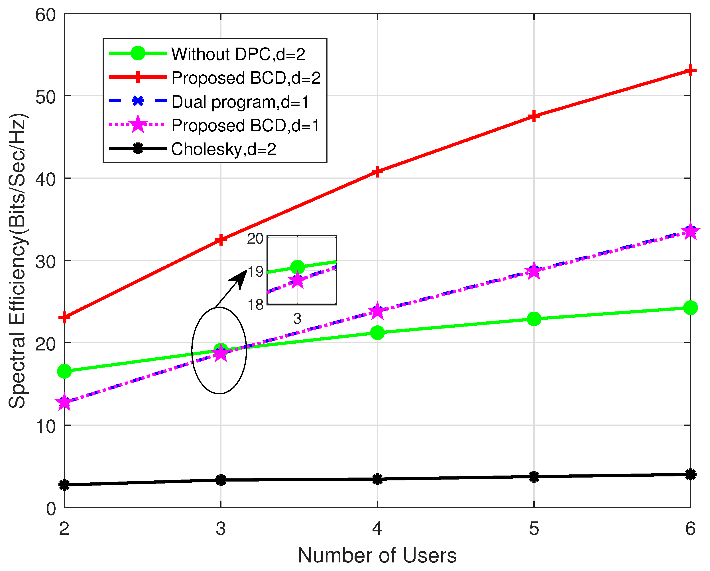
Figure 4 plots spectral efficiency against the number of users under different schemes, where we set
and SNR
dB. It is shown that the proposed BCD scheme obtains the best performance. As the number of users increases in the DFRC system, we observe that the overall spectral efficiency improves more if DPC is adopted at the transmitter. This is due to the fact that the transmit beamforming matrix is confined by the transmit covariance constraint, and the interference among different users cannot be eliminated effectively by linear precoding technology. Hence, when more users are introduced into the system, the interference imposed on other users increases significantly, leading to worse performance than the DPC-based scheme.
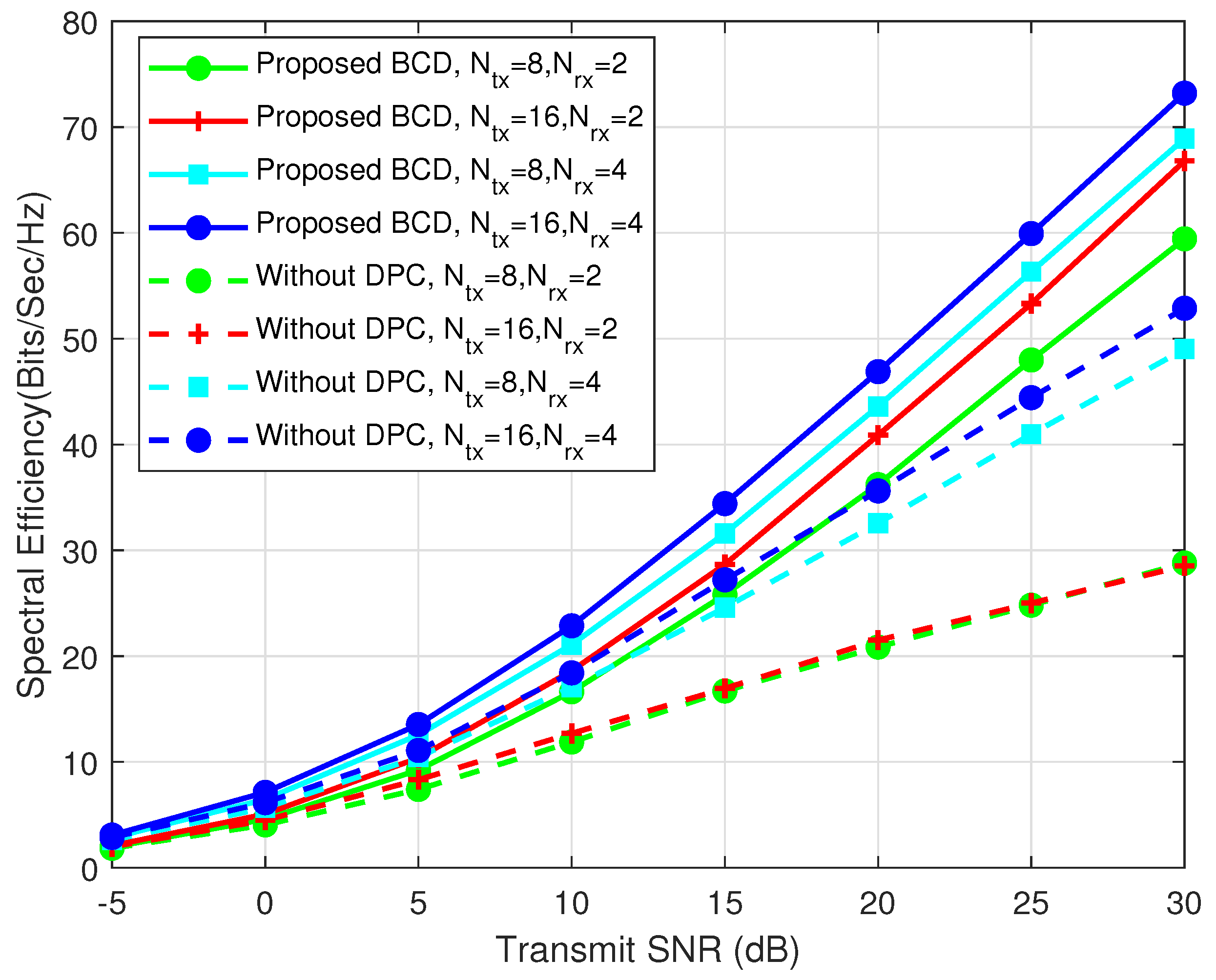
Figure 5 illustrates spectral efficiency at varying transmit SNRs alongside diverse configurations of transmitting and receiving antennas. Enhanced spectral efficiency is observed when each user is outfitted with additional receiving antennas, owing to the provision of heightened diversity gain. Nevertheless, in the absence of DPC at the transmitter, spectral efficiency experiences only marginal augmentation with an escalation in the number of transmitting antennas, particularly notable when
. This phenomenon stems from the transmit covariance constraint hindering the effective utilization of the supplementary degrees of freedom introduced by an expanded number of transmitting antennas. Conversely, for the DPC-based DFRC system, discernible enhancements in communication performance are apparent with an increase in either transmitting or receiving antennas.
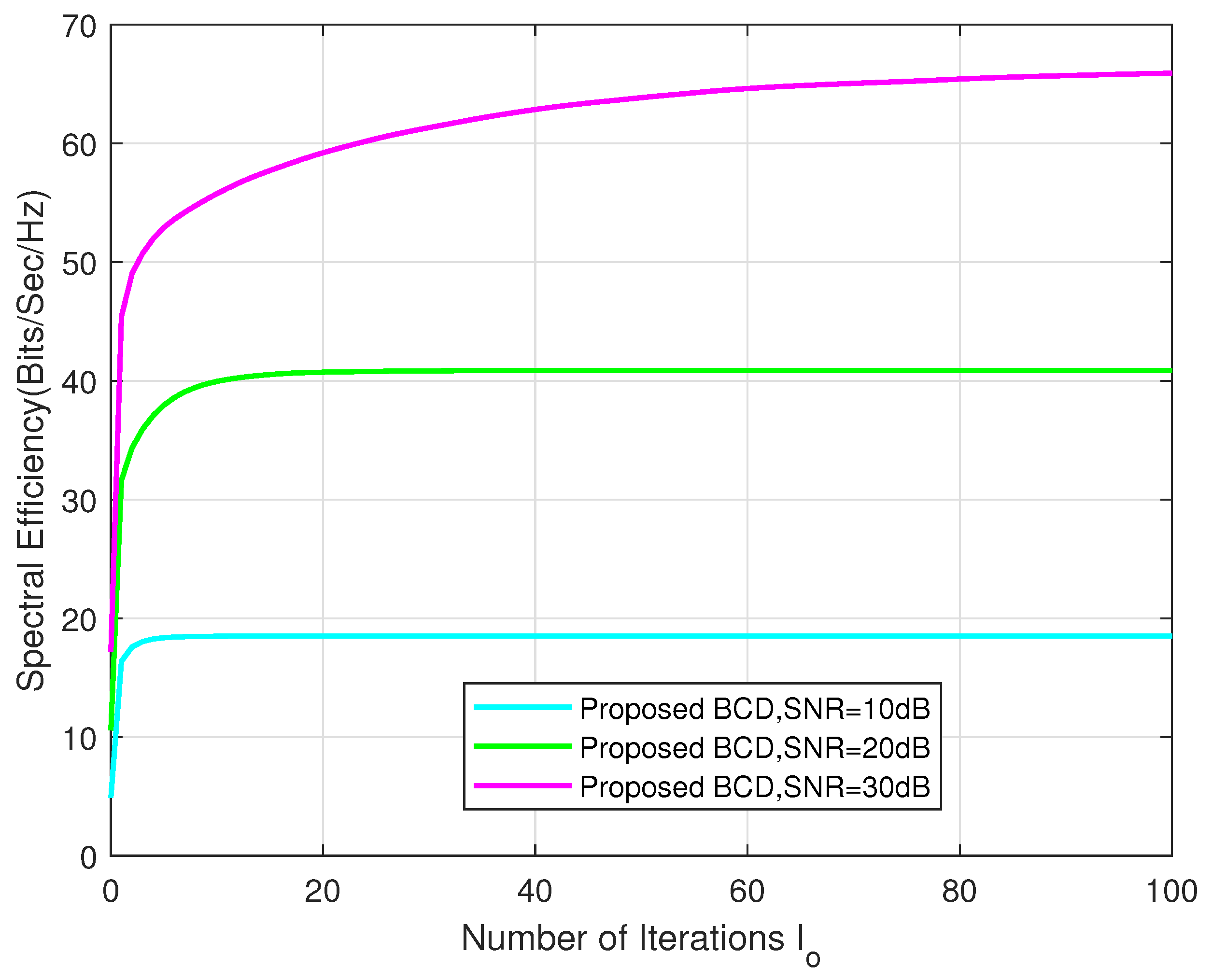
Figure 6 shows the convergence behavior of the proposed algorithm (Algorithm 1) under different transmit SNRs with
,
, and
. It is evident that the proposed BCD scheme converges within only a few iterations, especially in a low SNR regime. To be specific, when SNR = 10 dB or 20 dB, the algorithm converges within about ten iterations. When SNR = 30 dB, as much as 85% of the converged spectral efficiency can be obtained after ten iterations.

