Article

Multi-Objective Immune Optimization of Path Planning for Ship Welding Robot

1
School of Mechanics and Power Engineering, Jiangsu University of Science and Technology, Zhangjiagang 215600, China
2
Jiangsu Institute of Automation, Lianyungang 222006, China
3
Suzhou SmartImageAI Technology Co., Ltd., Zhangjiagang 215600, China
*
Author to whom correspondence should be addressed.
Electronics 2023, 12(9), 2040; https://doi.org/10.3390/electronics12092040
Submission received: 10 February 2023 / Revised: 18 April 2023 / Accepted: 25 April 2023 / Published: 28 April 2023
(This article belongs to the Special Issue Autonomous Robots and Systems)

Abstract

:
In order to improve the welding efficiency of the ship welding robot, the path planning of the welding robot based on immune optimization is proposed by taking the welding path length and energy loss as the optimization goals. First, on the basis of the definition of the path planning of the welding robot, the grid modeling of the robot’s working environment and the triangular modeling of the welding weldments are carried out. Then, according to the working process of the welding robot, the length objective function, including the welded seam path and the welding torch path without welding, is constructed, and the energy loss function is constructed based on the kinematics and Lagrange function. Finally, the immune optimization algorithm based on cluster analysis and self-circulation is introduced to realize the multi-objective optimization of the path planning for the ship welding robot. The test results of four kinds of ship welding weldments show that compared with the simple genetic algorithm, immune genetic algorithm, ant colony algorithm, artificial bee colony, particle swarm optimization, and immune cloning optimization, the proposed multi-objective immune planning algorithm is the best in terms of planning path length, energy consumption, and stability. Furthermore, the average shortest path and its standard deviation, the average minimum energy consumption and its standard deviation, and the average lowest convergence generation and its standard deviation are reduced by an average of 9.03%, 54.04%, 8.23%, 19.10%, 27.84%, and 52.25%, respectively, which fully verifies the effectiveness and superiority of the proposed welding robot path planning algorithm.

1. Introduction

Welding is the main process of shipbuilding, but the working environment is very harsh due to welding fume and metal spatter. Therefore, robot-based automatic welding has become the development trend in the shipbuilding industry, and path planning is the core of improving robot efficiency. As the number of welding spots increases, the difficulty of welding path combination optimization further increases. High-dimensional optimization has always been a technical difficulty in the engineering field, and the rapid development of intelligent optimization provides an effective solution [1,2,3,4]. How to improve the accuracy and efficiency of welding robot path planning based on intelligent algorithms has also become the focus of attention. Wang et al. proposed an improved ant colony algorithm with dynamic adaptive parameters for the welding path planning of complex ship components [5]. The simulation results show that the welding efficiency was improved while the welding quality is guaranteed, but the optimization model only takes the length of the welded seam as the goal, and the ant colony algorithm has no advantages in discrete variable optimization. When the number of welding spots increases, its optimization effect needs to be tested. Nie et al. used the improved Drosophila algorithm to optimize the welding path of the side wall of the car body by taking the minimum welding distance as the objective function, but its optimization model did not consider the energy loss [6]. Xue et al. proposed a multi-objective-based welding path planning for the robot welding of automobile body-in-white, but in the planning process, only the welding spots that form the weld were planned, and the spatial movement of the welding robot without welding was not considered [7]. Wang et al. realized robot path planning based on particle swarm optimization algorithm with elite strategy under the condition of considering mutual influence for the path planning of dual-welding robot, but the energy loss in the welding process is also not further discussed in the paper [8]. Yao et al. constructed a mathematical model of path planning including collision costs based on the motion characteristics of the welding robot and proposed an improved bee colony algorithm to achieve path optimization, but the energy loss was also not considered, and the optimization effect of the bee colony algorithm on the multi-spot data also needs to be further tested [9]. Gao et al. carried out the path optimization research of a welding robot based on the ant colony optimization (ACO) algorithm and genetic algorithm (GA). The shortest path of the robot is optimized mainly using the ACO algorithm, and the shortest trajectory is optimized using GA. Simulation experiments show that the optimization strategy of ACO can increase the iterative calculation efficiency and path optimization performance of the algorithm [10]. However, in the process of path optimization, the energy loss and empty operation path of the welding robot are not considered. For the welding task of large complex weldments, Wang et al. first established an optimization model based on the actual welding process constraints and the shortest welding path, then proposed an improved ACO algorithm based on the dynamic transfer strategy and information update strategy, and finally realized the dual-robot collaborative welding optimization based on the improved ACO algorithm [11]. The simulation results show that compared with the traditional ACO algorithm, the proposed improved algorithm has the advantages of faster convergence speed and shorter welding path. Zhang et al. carried out the path planning of a welding robot based on a hybrid global optimal beetle antenna search-genetic algorithm for the welding task of automobile body-in-white [12]. The genetic algorithm is added to each iteration of the beetle antenna search (BAS) algorithm, and the advantage of fast convergence of BAS is used to accelerate the convergence speed of the GA. The simulation results show that the BAS-GA has good practicability in welding path planning. However, the path optimization model is only constructed based on the coordinates of the welding spots in the three-dimensional space. Additionally, for the welding task of automobile body-in-white, Xu et al. built a mathematical model based on the analysis of the welding process and realized the multi-robot welding path planning based on the improved ant colony optimization algorithm by improving the heuristic function, which improved the rationality of robot welding [13]. However, the construction of the objective function of ant colony optimization is only based on the distance between the robot coordinates and the target point coordinates.
From the existing research, it can be seen that the path planning of the welding robot has attracted attention, but the construction of the existing optimization model for the path planning is relatively one-sided, that is, the model is only one-sidedly based on the length of the welded seam, and the moving path of welding torch without welding is not considered, or the energy consumption of the welding robot is not considered, which makes it impossible for welding robots to obtain the globally optimal path and operate with low energy consumption. In addition, robot path planning is usually a multi-variable and multi-objective combinatorial optimization problem. In recent years, although intelligent optimization algorithms have provided effective solutions for path planning [14,15,16,17,18], in the field of welding robot path planning, the complexity of path optimization will increase explosively with the increase in the number of welding spots. Traditional intelligent optimization algorithms are often difficult to adapt to high-dimensional optimization. In view of the above reasons, on the one hand, a multi-objective optimization model of a ship welding robot including path length and energy consumption is built in this paper, and, on the other hand, a new immune optimization algorithm with a strong search ability is introduced to realize the global and high-precision path planning of welding robots.
This article is arranged as follows. Section 2 provides the definition and modeling of welding robot path planning. Section 3 provides the construction of an objective function for the path planning of welding robots. Section 4 describes the multi-objective immune optimization of welding path planning. The test and analysis of multi-objective path planning are described in Section 5. Section 6 offers experimental research on the path planning of welding robots. Finally, the conclusions and future work are stated in Section 7.

2. Definition and Modeling of Welding Robot Path Planning

2.1. Path Planning Definition

The path planning of the ship welding robot [19] can be described as the robot welding torch starting from a welding spot and traversing all the welding spots with the shortest path. The path includes not only the welded seam distance where the welding spot is located but also the barrier-free movement distance of the welding torch without welding among welding spots. If there are N welding spots C = {c1, c2, …, cN} on the weldment, as shown in Figure 1, and the distance between welding spot ci and cj (i, j∈[1, N] and ij) is recorded as d(ci, cj), then the path planning of the welding robot can be described as a combinatorial optimization problem
min i , j = 1 i , j = N d ( c i , c j )
In Figure 1, O1O6 represents the coordinate system of the six joints of the welding robot.

2.2. Environmental Modeling

From the above, it can be seen that the path planning of the ship welding robot is somewhat similar to the traveling salesman problem (TSP), but not exactly the same. The path planning of the welding robot includes not only the weld distance but also the moving distance of the welding torch without welding. The distance of the former can be accumulated according to the length of the welded seam, but the latter requires barrier-free planning in the welding spot space [20], which is inseparable from the environment modeling of the welding robot. In view of the fact that most of the robot weldments are regular bodies, the grid method is used to model the robot environment in this paper, and the weldments are modeled by triangles, as shown in Figure 2.
In grid environment modeling, the grid size directly affects the accuracy and efficiency of robot path planning. If the grid is too small, although the planned path length will be reduced and the obstacle avoidance efficiency of the robot will be improved, the calculation amount will increase during the planning; if the grid is too large, although the calculation amount can be reduced, it will increase the length of path planning and reduce the obstacle avoidance efficiency of the robot [21]. In order to balance the calculation amount and the obstacle avoidance efficiency, a grid with a side length of 100 mm is used to model the robot environment in this paper. In order to judge whether there is a collision during the movement of the welding robot, the robot grid is projected onto the triangular workpiece plane, and the collision is determined by judging whether the projection point is inside the triangle.

3. Construction of Objective Function for Path Planning of Welding Robot

The path planning of the welding robot should not only consider the welded seam and the moving path of a welding torch without welding but also consider the robot’s energy consumption. In order to achieve low energy consumption under high welding efficiency, a multi-objective optimization function is constructed based on path length and energy consumption.

3.1. Objective Function Based on Path Length

3.1.1. Path Length Based on Welded Seam

The welded seam forms of ship weldments usually include straight lines and arcs. The former can obtain the planned path length through the endpoint coordinates, but the latter cannot directly obtain the length through the endpoint coordinates. In order to improve the planning accuracy of the welding robot, the interpolation point connection method [20] is used to calculate the arc path length in this paper. If the planning path of the robot welding torch that needs to be traversed is T = { t1, t2,…, tN}, then ∀ i∈[1, N], tiC. tj, tj+1 (j ∈ [1, N − 1]) are the endpoints of one arc weld, and if the P intermediate points S = {s1, s2, …, sP} are evenly interpolated for the arc segment, then the length of the planned path can be defined as
R s ( C ) = i = 1 , i j N 1 d ( t i , t i + 1 ) + i = 1 P 1 d ( s i , s i + 1 ) + d ( t j , s 1 ) + d ( s P , t j + 1 )
If there are multiple arc welds, the same interpolation method is used to sum the path lengths.

3.1.2. The Moving Length of the Welding Torch without Welding

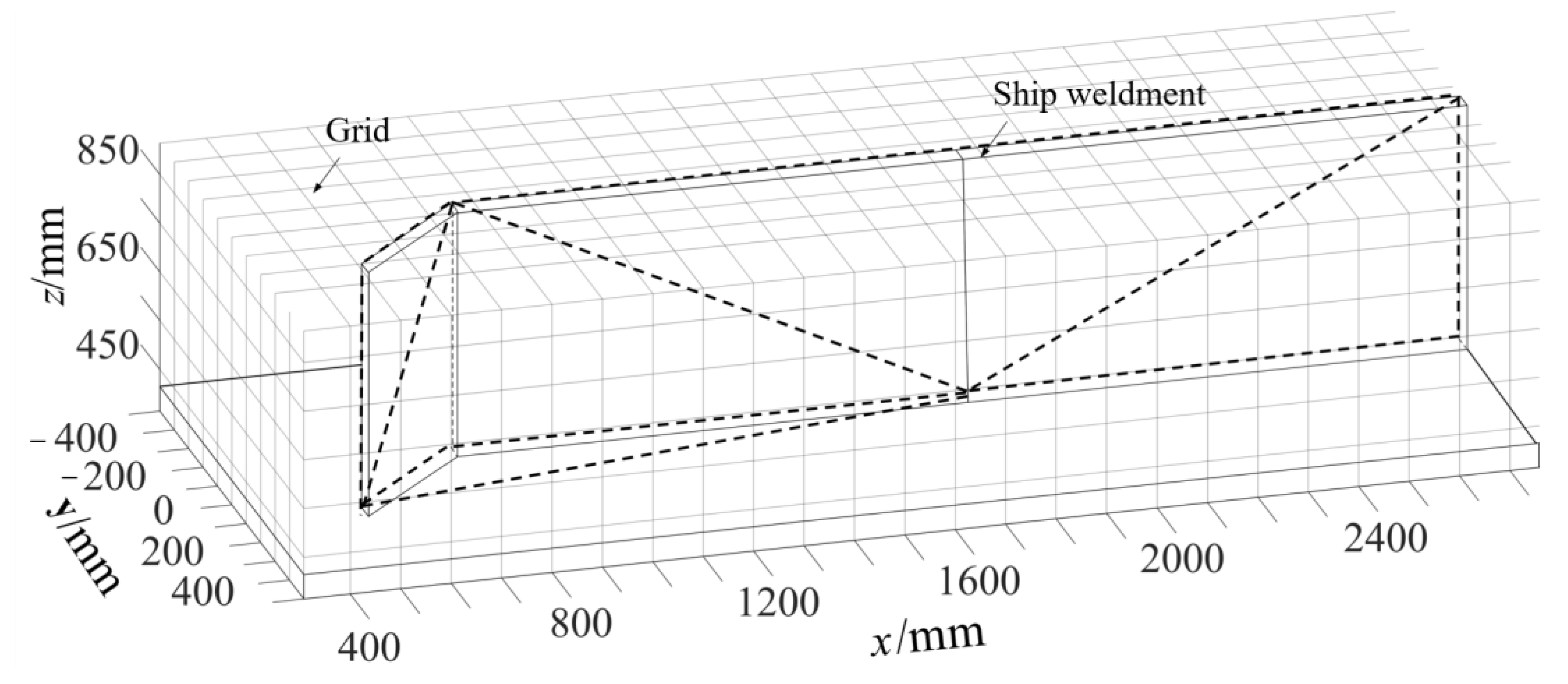
As shown in Figure 3, assuming that there are welding spots u and v (u, vC) on the convex back of the weldment, now the welding torch needs to move from spot u to spot v without welding and with the shortest distance without collision. According to the grid modeling of the environment and the triangle modeling of the weldments, there is an intersection line EF at the intersection of the triangle plane where the welding spots u and v are located. When there is no welding, the planning of the moving path of the welding torch between the welding spots u and v is changed to search for the optimal spot w on the EF intersection line. The spot w can be obtained by a similar Newton iterative method, and the optimal path length Rg(C) of the corresponding welding torch without welding can be obtained. The lengths of multiple paths without welding by the torch can then be superimposed.

3.1.3. Total Welding Path Length f(C) of Welding Robot

Based on the planned length Rs(C) of the welded seam and the optimal path length Rg(C) of the welding torch without welding, the total welding path length f(C) can be described as
f ( C ) = R s ( C ) + R g ( C )

3.2. Objective Function Based on Energy Loss

Path planning based on path length can improve the efficiency of welding robots, but energy consumption needs to be considered to reduce the cost of robot operation. In this paper, based on the analysis of welding robot dynamics [22,23,24], the energy loss objective function [25] is constructed according to the system kinetic energy and potential energy, and the quintic polynomial is adopted in the trajectory planning of the welding robot.
Let the displacement time function of a certain joint of the welding robot be
θ ( t ) = a 0 + a 1 t + a 2 t 2 + a 3 t 3 + a 4 t 4 + a 5 t 5
where ai (i = 1, 2, 3, 4, 5) is the coefficient of the polynomial.
Carry out the first derivative and the second derivative, respectively, in Equation (4) to obtain joint angular velocity and angular acceleration functions:
θ ˙ ( t ) = a 1 + 2 a 2 t + 3 a 3 t 2 + 4 a 4 t 3 + 5 a 5 t 4
θ ¨ ( t ) = 2 a 2 + 6 a 3 t + 12 a 4 t 2 + 20 a 5 t 3
For the welding robot system, the Lagrange equation can be used to solve the energy loss on the basis of analyzing the system dynamics. The specific steps are as follows:
Step 1 
Calculate the kinetic energy and potential energy of the system according to the robot pose at the two welding spots.
Assuming that the number of connecting rods of the welding robot is s, the position of the center of mass of the connecting rod i (i ∈ [1, s]) in the coordinate system is pi, and if the mass of the connecting rod i is mi, then the kinetic energy of the robot system is
E k = i = 1 s E k i = i = 1 s 1 2 θ ˙ i 2 m i
The potential energy of the robot system is
E p = i = 1 s E p i = i = 1 s m i g p i
Step 2 
Solve the torque of all joints of the welding robot using inverse dynamics.
In order to solve the energy loss of the welding robot, the Lagrange function L is introduced to represent the difference between the kinetic energy Ek and the potential energy Ep of the system [25], namely,
L = E k E p
The torque τ of the joint is
τ = d d t L θ ˙ L θ = d d t E k θ ˙ E k θ + E p θ
Step 3 
Calculate the energy consumption of the robot moving between the following two welding spots:
e Δ = 0 T ( θ ˙ τ ) 2 d t
where T is the total time that the robot moves between two welding spots.
Step 4 
Calculate the total welding energy consumption by adding the energy consumption between all welding spots according to the planning path of the welding robot.
e ( C ) = i = 1 N 1 e Δ ( c i , c i + 1 )
where e(ci, ci+1) is the energy loss between the welding spot ci and ci+1, and N is the total number of welding spots.

3.3. Multi-Objective Optimization Function

In order to obtain the optimal planning path of the ship welding robot with high efficiency and low energy consumption, a multi-objective optimization function is constructed based on the planning path length and energy loss, but the two are not only different in dimension but also not in the same order of magnitude. If they are superimposed directly by weight, the performance impact of the two in path optimization cannot be exerted. Therefore, in this paper, the data of the two indicators are first normalized and then reweighed to construct a multi-objective optimization function.
Normalize the path length:
F ( C ) = max ( f ( C ) ) f ( C ) max ( f ( C ) ) min ( f ( C ) )
where max (·) and min (·) represent the maximum and minimum calculation functions, respectively.
Normalize the energy loss:
E ( C ) = max ( e ( C ) ) e ( C ) max ( e ( C ) ) min ( e ( C ) )
The multi-objective optimization function of welding robot path planning is
f = α 1 F ( C ) + α 2 E ( C )
where α1 and α2 are weight coefficients.

4. Multi-Objective Immune Optimization of Welding Path Planning

4.1. Immune Algorithm Based on Cluster Analysis and Self-Circulation

The immune optimization algorithm inspired by the immune information processing mechanism has been successfully applied in various engineering fields in recent years because of its strong optimization ability [26,27,28]. In order to improve the path planning accuracy and efficiency of the ship welding robot, the immune optimization algorithm is introduced in this paper. The basic immune optimization algorithm includes operators such as immune selection, immune crossover, and immune mutation. However, as the variables of the optimization object increase, the basic immune optimization algorithm usually falls into local minimum and premature, which affects the optimization performance of the algorithm. In addition, the path planning of a welding robot is somewhat similar to the TSP problem. In view of this, the immune optimization algorithm based on cluster analysis and self-circulation (IOACS) [29] is introduced in this paper. The algorithm is designed for solving TSP problems based on the basic immune evolution algorithm. On the one hand, the population data are classified and evolved according to the relevance of the problem, and the cluster analysis concept is used to improve the efficiency of population optimization; on the other hand, the self-circulation strategy is designed, and the new offspring are obtained through the self-circulation crossover of the parent, and then the gene fragments of the excellent individuals are passed to the offspring to improve the global search ability of the algorithm. The core operators of the algorithm include clustering, self-circulation crossover, and adaptive mutation operators.

4.1.1. Clustering Operator

Assuming that k initial cluster centers Ć (ć1, ć2, …, ćk) are given, a new center H(h1, h2, …) is obtained after the clustering operation is performed according to the distance between two cluster centers. This operator can be described as HT(Ć). The detailed operation steps of the clustering can be found in [29].

4.1.2. Self-Circulation Crossover Operator

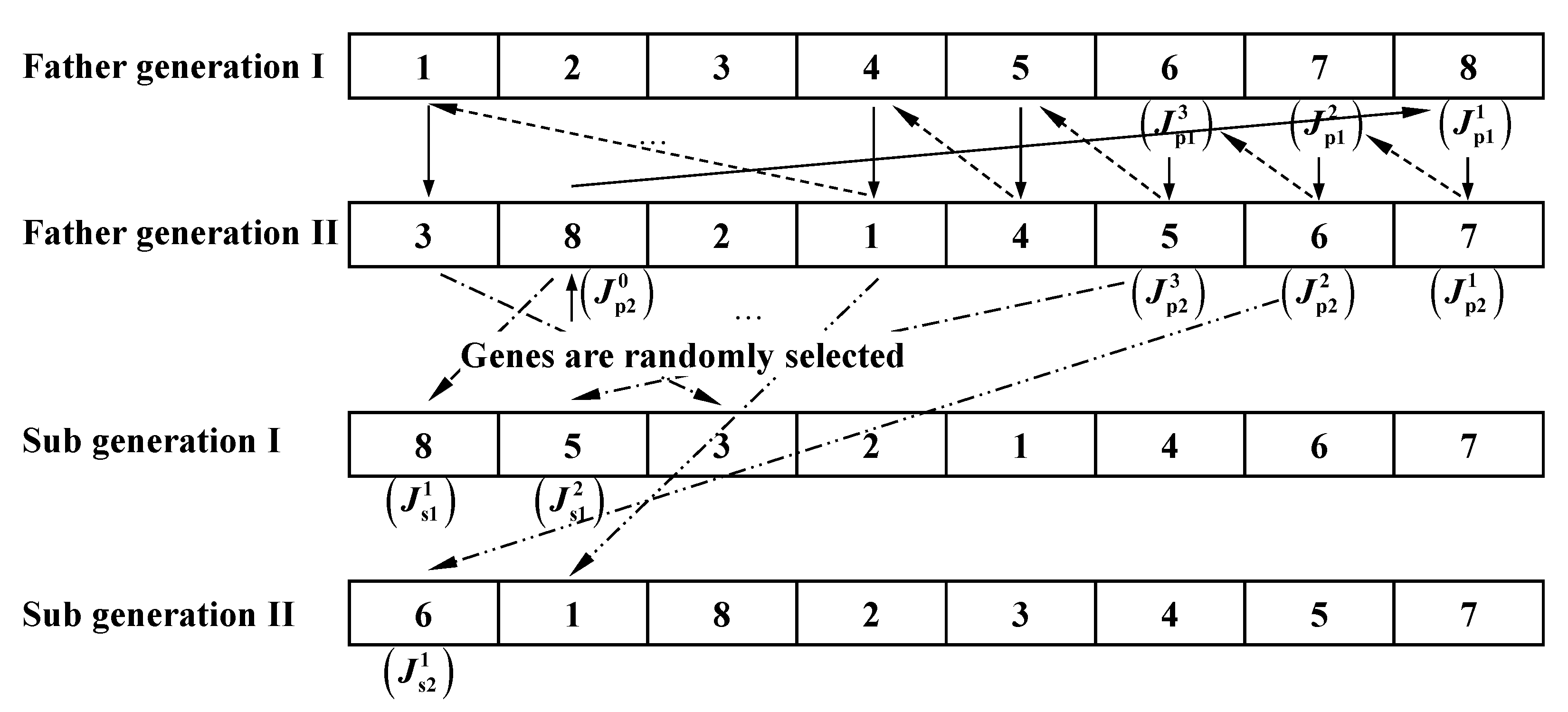
Crossover is the core operation of the immune algorithm. Circular crossover [30] can obtain multiple crossover positions mainly by randomly selecting a position in the parent. Its operation diagram is shown in Figure 4.
The self-circulation crossover operator is mainly used to select the individuals to be crossed in the parent population A(k) first using the adaptive selection probability in Equation (16) and then performing circular cross-selection on the selected individual bits in the parent generation to form a new individual population A’(k). This operator can be described as A’(k)←Tc(A(k)). The detailed operation steps of crossover can be found in [29].
P c = { ( P c 1 P c 2 ) ( f f a v g ) f max f a v g , f < f a v g P c 2 , f f a v g
fmax is the maximum individual fitness value in the population, favg is the average fitness value of the population, f′ is the fitness value of the individual to be crossed in the parent generation, Pc1 is the threshold of the maximum crossover rate, and Pc2 is the threshold of the minimum crossover rate.

4.1.3. Adaptive Mutation Operator

For the antibody group A’(k) after the crossover, the adaptive mutation operation is performed based on the mutation probability Pm in Equation (17): A’’(k)←Tm(A’(k)).
P m = { ( P m 1 P m 2 ) ( f f a v g ) f max f a v g , f f a v g P m 2 , f < f a v g
where Pm1 is the threshold of the maximum mutation rate, Pm2 is the threshold of the minimum mutation rate, and f′′ is the fitness value of the individuals to be mutated in the parent generation.

4.2. Multi-Objective Immune Optimization Process for Path Planning

Step 1 
Parameter initialization: population size N, iteration generation k, maximum evolutionary generation kmax, k←0, etc.
Step 2 
Initialize the cluster center Ć according to the coordinate data of the welding spots, and then perform welding spot clustering HT(Ć) and obtain each new sub-clustering center H(h1, h2, …).
Step 3 
Search for the optimal planning path for each subclass in H using IOACS.
i = 1, 2,…, initialize the population A(0) for the subclass containing the cluster center hi.
Perform self-circulation crossover operator.
Perform adaptive mutation operator.
Perform immune selection on A’’(k), and obtain a new population A(k + 1).
Judge whether all classes in H have completed the shortest path planning? If they have, then go to Step 4 (otherwise, go to ①).
Step 4 
Plan the clustering center using IOACS for each cluster center h1, h2,…, hk in H.
Step 5 
Perform the connection of each sub-category clustered by adjacent welding spots according to the path of the cluster center planned in Step 4.
Firstly, select the welding spots ci, cj which are the closest to each other in the two classes as connection points, and then select the welding spots ci, cj adjacent to ci, cj as the second group of connection points, respectively, according to the Equation (18), and delete the connection edges (ii’, jj’).
( i , j ) = arg min ( d i j + d i j d i i d j j d i j + d i j d i i d j j )
dij represents the distance between welding spots ci and cj, and the rest of the definitions are the same.
Step 6 
Output the optimal path of the welding robot and terminate the planning.

5. Test and Analysis of Multi-Objective Path Planning

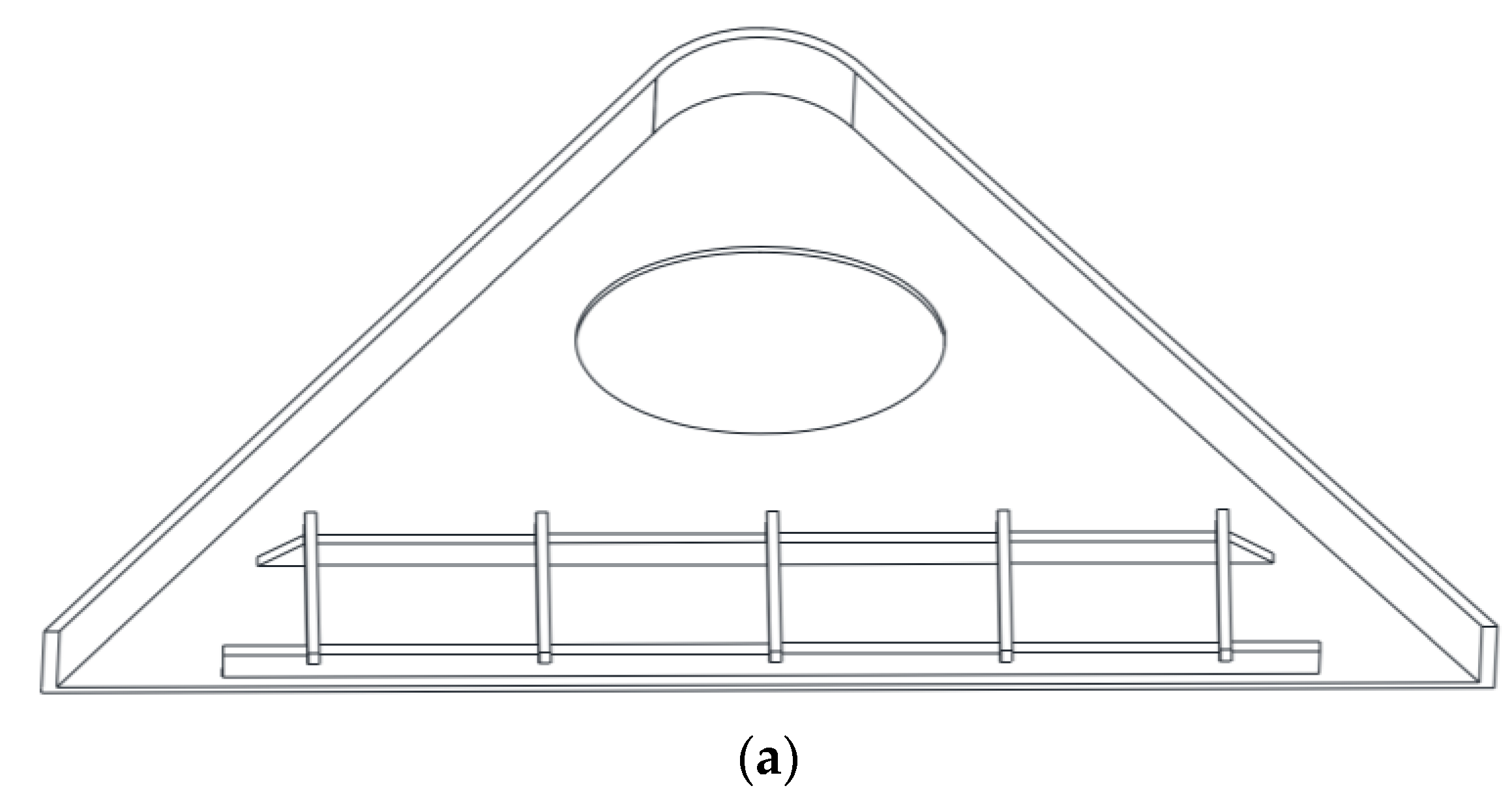
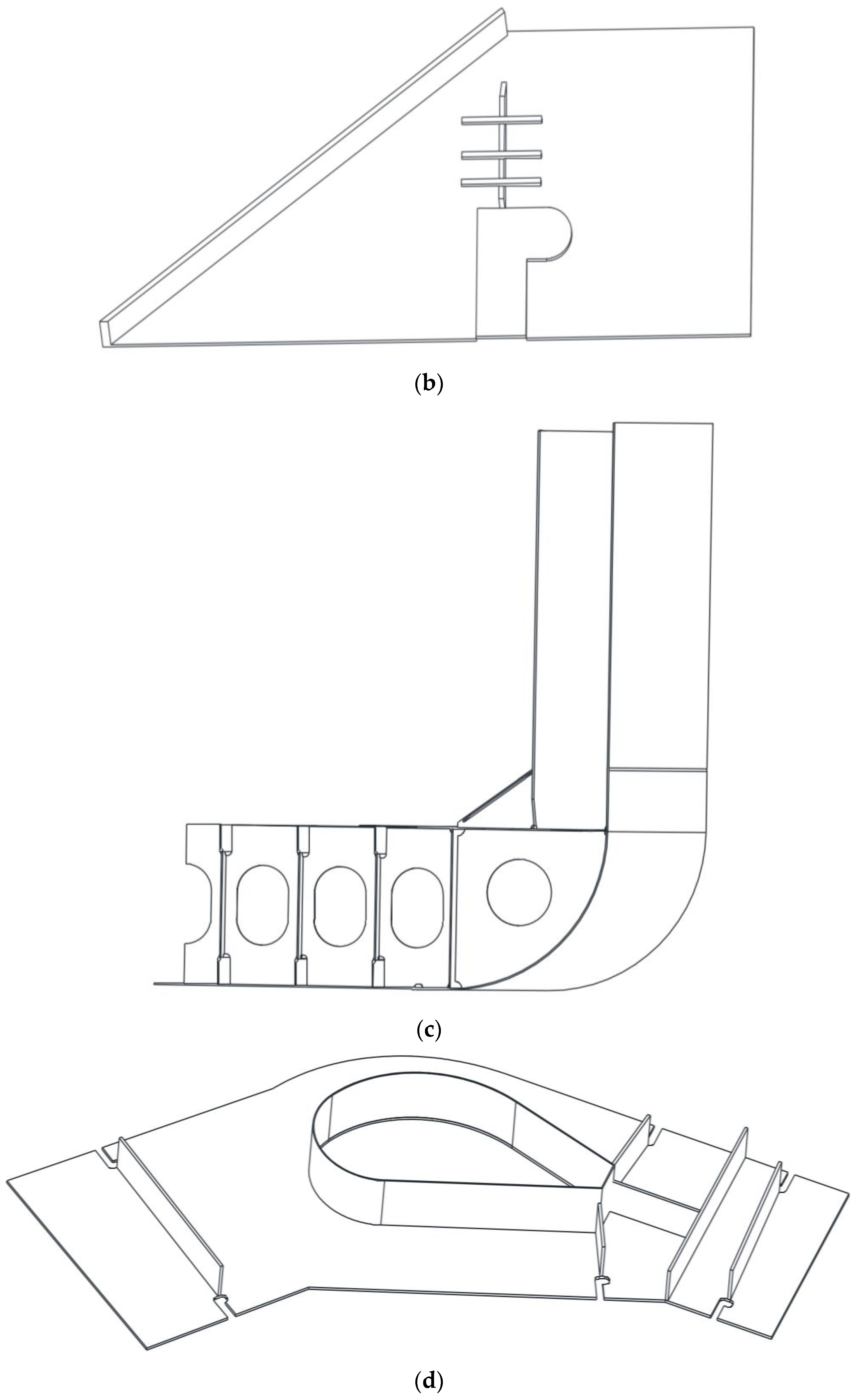
In order to verify the effectiveness and superiority of the proposed multi-objective path planning for welding robots based on IOACS, some path planning tests were carried out on a PC platform with CPU 3.1 GHz and 4 G RAM for the four ship weldments shown in Figure 5, and the test results were compared with those of the simple genetic algorithm (SGA) [31], the immune, genetic algorithm (IGA) [32], the ant colony optimization (ACO) [33], the artificial bee colony (ABC) [34], the particle swarm optimization (PSO) [35] and the immune cloning optimization [ICO] [36]. Because the ship weldments in Figure 5 include straight welds and curve welds, they are universal and meet the test of the path planning algorithm. The setting of IOACS parameters (N = 50, k = 5, Pc1 = 0.9, Pc2 = 0.5, Pm1 = 0.09, and Pm2 = 0.05) and weight coefficients α1 and α2 are 0.7 and 0.3, respectively. The population size of SGA and IGA is 50, and the selection, crossover, and mutation probabilities are 0.08, 0.5, and 0.03, respectively. The number of ants in ACO is 50, the pheromone inspiration factor is 1, the expected inspiration factor is 4, and the pheromone volatilization coefficient is 0.2. The population size of ABC is 20, the individual dimension of the honey source is 10, and the maximum limit is 20. The particle population size of PSO is 20, the inertia weight ω is 0.5, and the learning factors c1 and c2 are 0.03 and 0.04, respectively. The clone size of ICO is 100, the mutation probability pm is 0.1, the virus infection probability pr is 0.8, and the virus replication probability pc is 0.4. In view of the probabilistic search of intelligent optimization algorithms, 30 independent tests were carried out for each algorithm in this paper. The test results are shown in Table 1, Table 2 and Table 3.
From Table 1, it can be seen that for the four types of ship weldments, the length performance of the planned robot path based on IOACS in this paper is optimal. Compared with the test results of SGA, IGA, ACO, ABC, PSO, and ICO, the average shortest path length and its standard deviation of IOACS are reduced by an average of 9.03% and 54.04%, respectively. In addition, as the test weldment changes from the side plate to the bottom plate, the number of welding spots on the weldment also increases. Compared with the other six path planning algorithms, the performance advantages of the proposed robot path planning algorithm are more obvious and stable. These not only show the effectiveness of multi-objective path planning for welding robots based on IOACS but also fully reflect the strong optimization ability and good stability of the IOACS. This is mainly because, on the one hand, the algorithm ensures the diversity of the population through the self-circulation strategy to avoid falling into the local minimum and improve the global optimization ability; on the other hand, the clustering strategy is used to strengthen the connection of adjacent welding spots, which improves the local search ability. From Table 2, it can also be seen that the energy consumption of the welding robot planning based on the proposed algorithm is also the smallest. Compared with the other six algorithms, the average minimum energy consumption and its standard deviation of path planning based on the proposed algorithm are reduced by 8.23% and 19.10%, respectively, which not only further illustrates the effectiveness and superiority of the IOACS in the multi-objective path planning of welding robots, but also verifies that by reasonably constructing the multi-objective optimization function integrating the path length and energy consumption, the energy consumption of the robot can be reduced while ensuring that the path length is shortened. Table 3 shows the performance comparison of planning efficiency among the seven algorithms. From the table, it can be seen that the proposed algorithm has the highest planning efficiency and is the most stable. Compared with the other six algorithms, the average minimum convergence generation and standard deviation of the IOACS decreased by 27.84% and 52.25%, respectively. This is mainly because, on the one hand, the IOACS not only ensures population diversity through adaptive crossover and mutation and also achieves the retention of dominant antibodies in each generation, thus improving the efficiency of population evolution; on the other hand, the clustering strategy always ensures the priority connection of adjacent welding spots, thus improving the overall evolution efficiency of the algorithm.
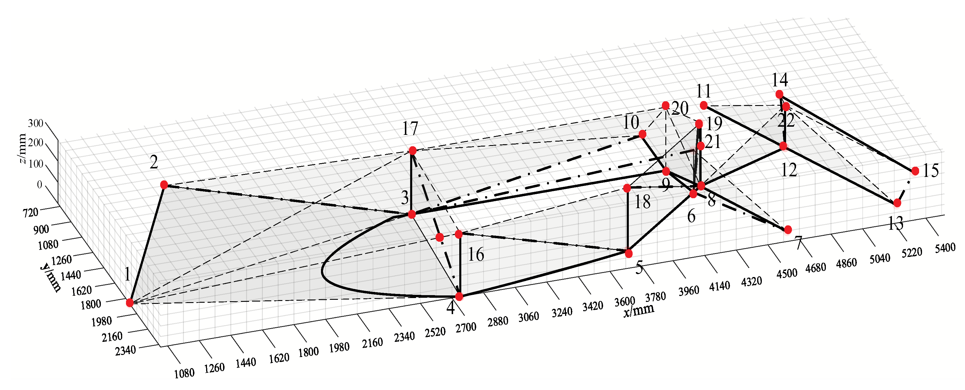
In order to further show the results of the multi-objective immune path planning of the proposed algorithm, and the comparison of the planning results among the seven algorithms, the bottom plate weldment with the largest number of welding spots is first illustrated as an example. Figure 6 shows the distribution and labeling of its initial welding spots. Table 4 shows its corresponding coordinates. In order to facilitate obstacle avoidance in the process of welding path planning, the environment modeling shown in Figure 7 is carried out for the base plate weldment in this paper. The collision is judged by the projection of the stereo grid method, and the geometric obstacle avoidance strategy based on the transition point is introduced to find the optimal transition point without welding according to the distribution of welding spots in different areas, so as to achieve effective obstacle avoidance and the shortest path during welding.
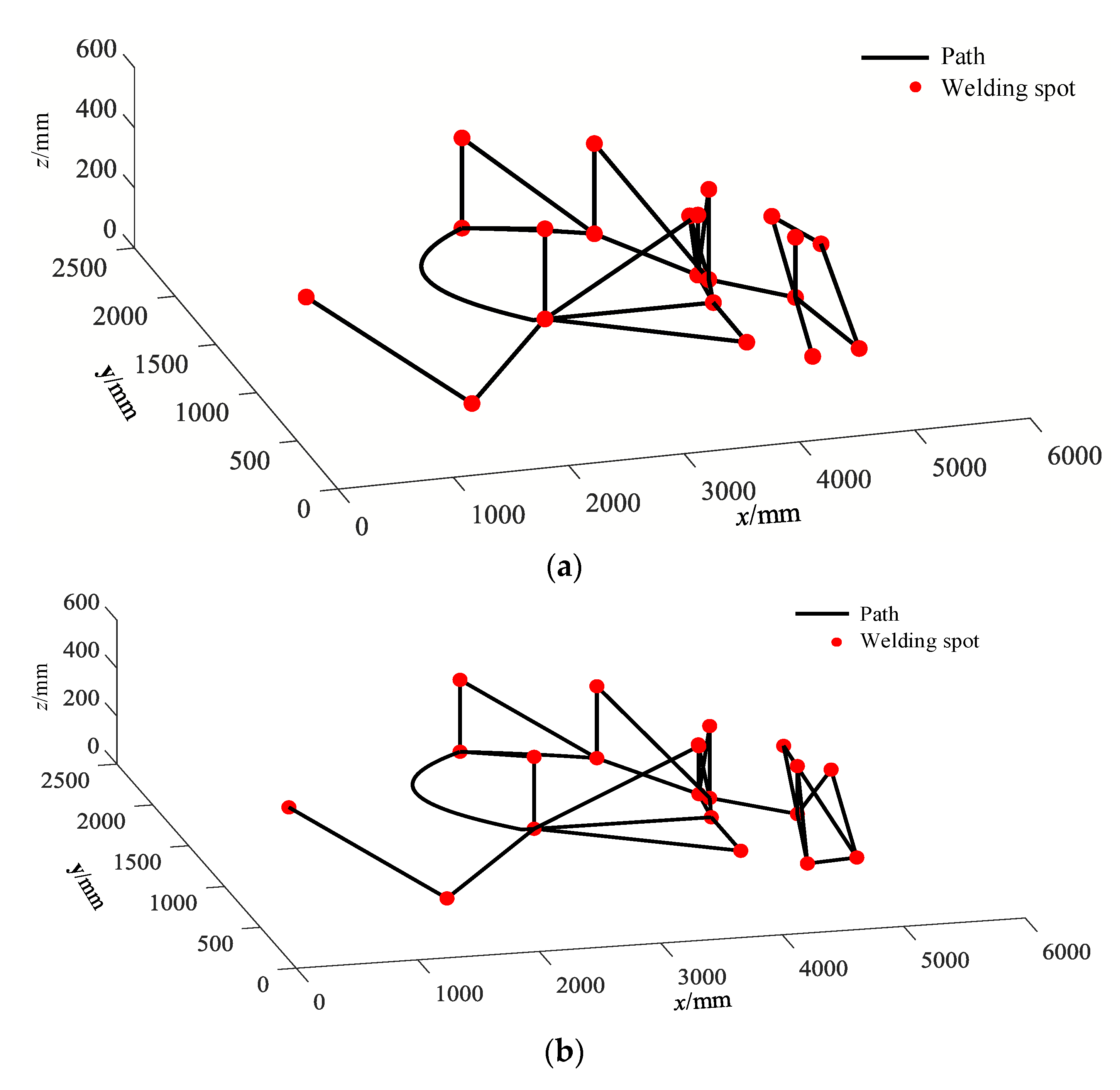
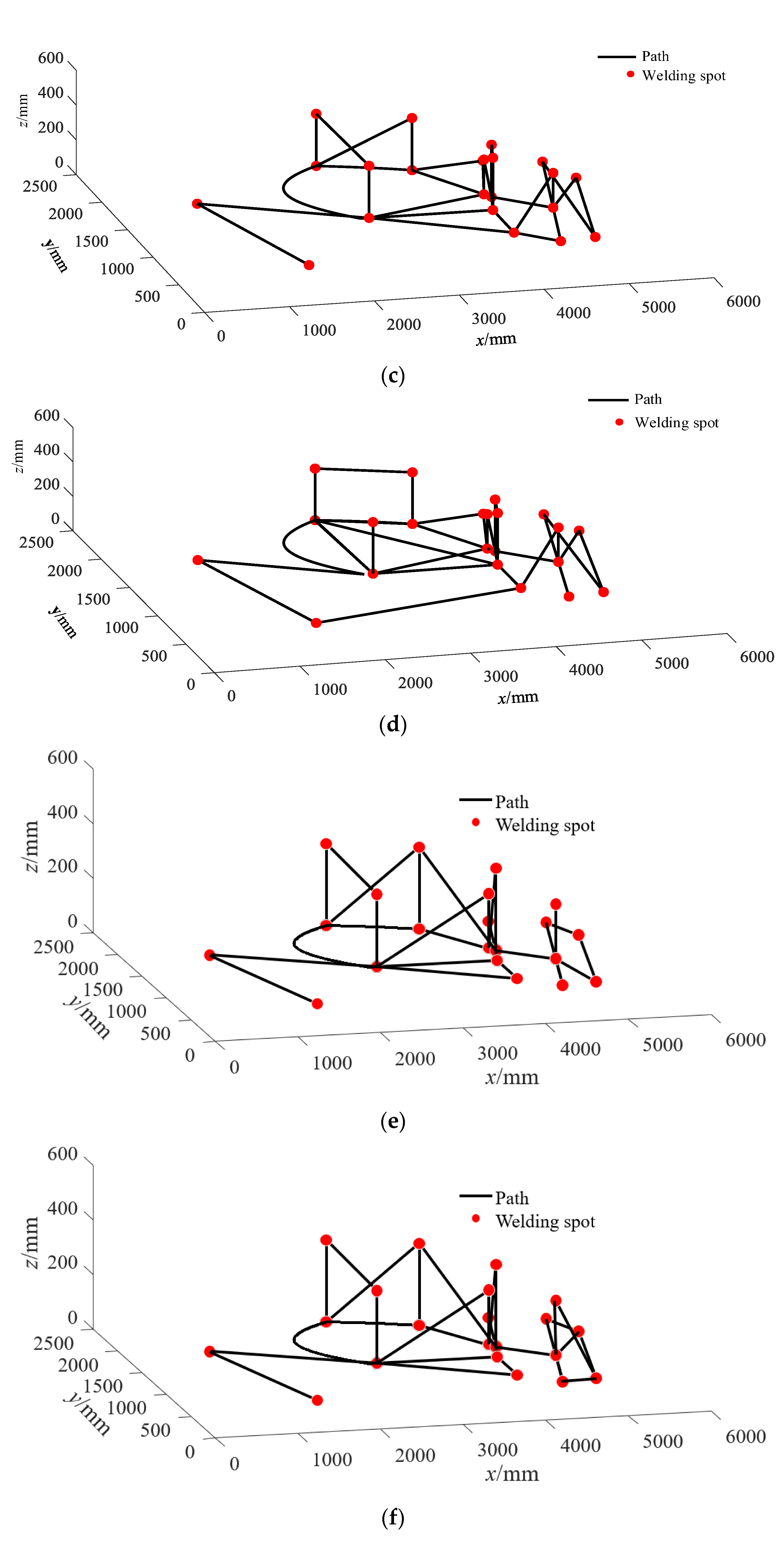
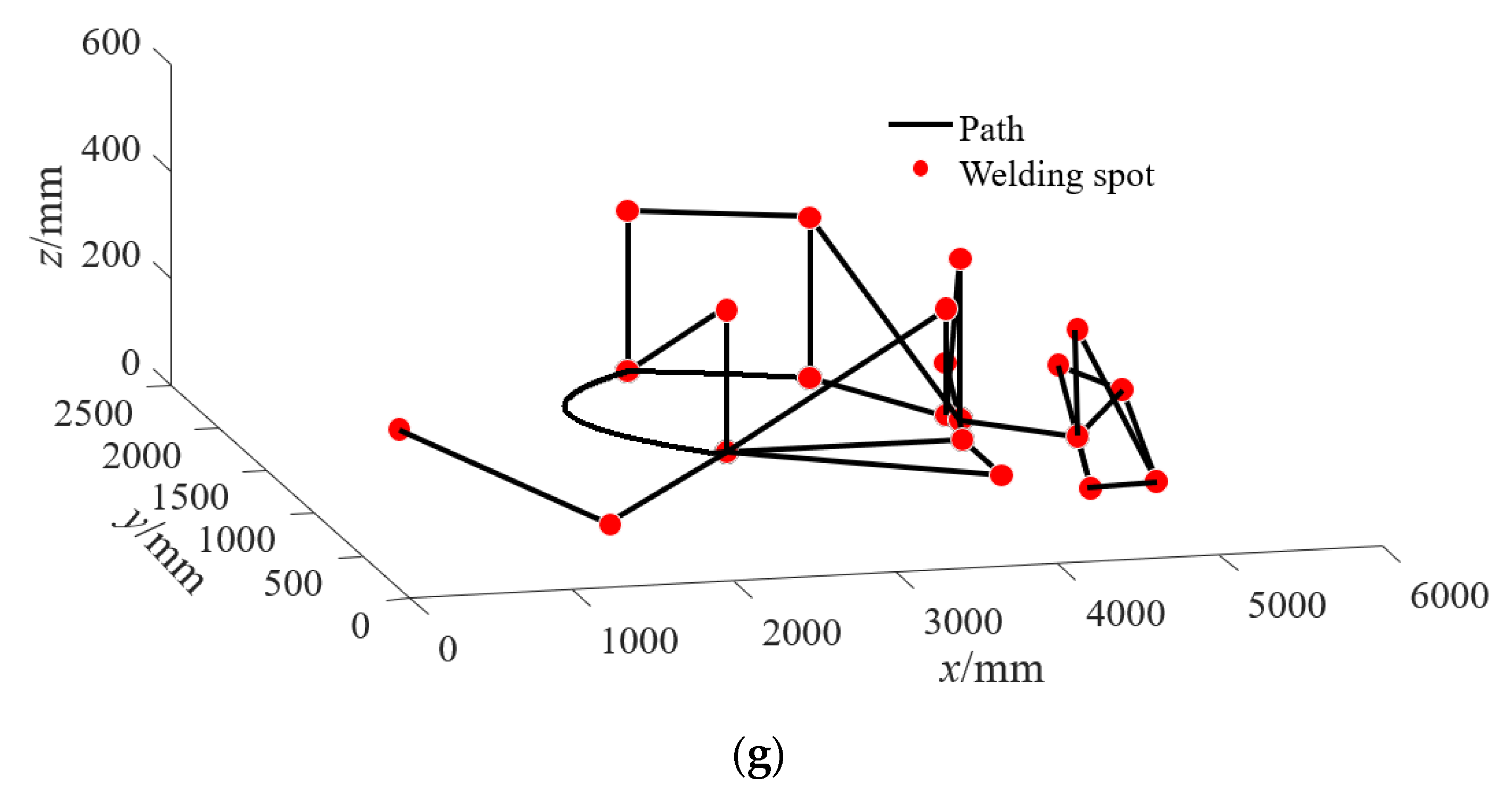
Figure 8 shows the planning results of the seven planning algorithms for the base plate weldment. The red dots in the figure indicate the welding spots that the robot welding torch needs to pass through during the welding process, and the straight line indicates the planned path, which includes the path of the welding seam and the moving path of the welding torch without welding. From the figure, it can be seen that different optimization strategies lead to different planning results. The optimal path sequence of the proposed multi-objective immune programming method is 1 → 2 → 3 → 4 → 5 → 8 → 9 → 20 → 10 → 3 → 17 → 4 → 16 → 5 → 18 → 8 → 19 → 6 → 21 → 3 → 9 → 7 → 6 → 8 → 12 → 11 → 13 → 14 → 15 → 12 → 22.
Figure 9 shows the evolution curves of the seven algorithms for the path planning of the bilge plate weldment. From the figure, it can also be seen that the multi-objective immune planning algorithm has the fastest convergence speed, the planned path is the shortest, and the energy consumed by the robot is the least amount of energy, which further verifies the effectiveness and superiority of the algorithm.
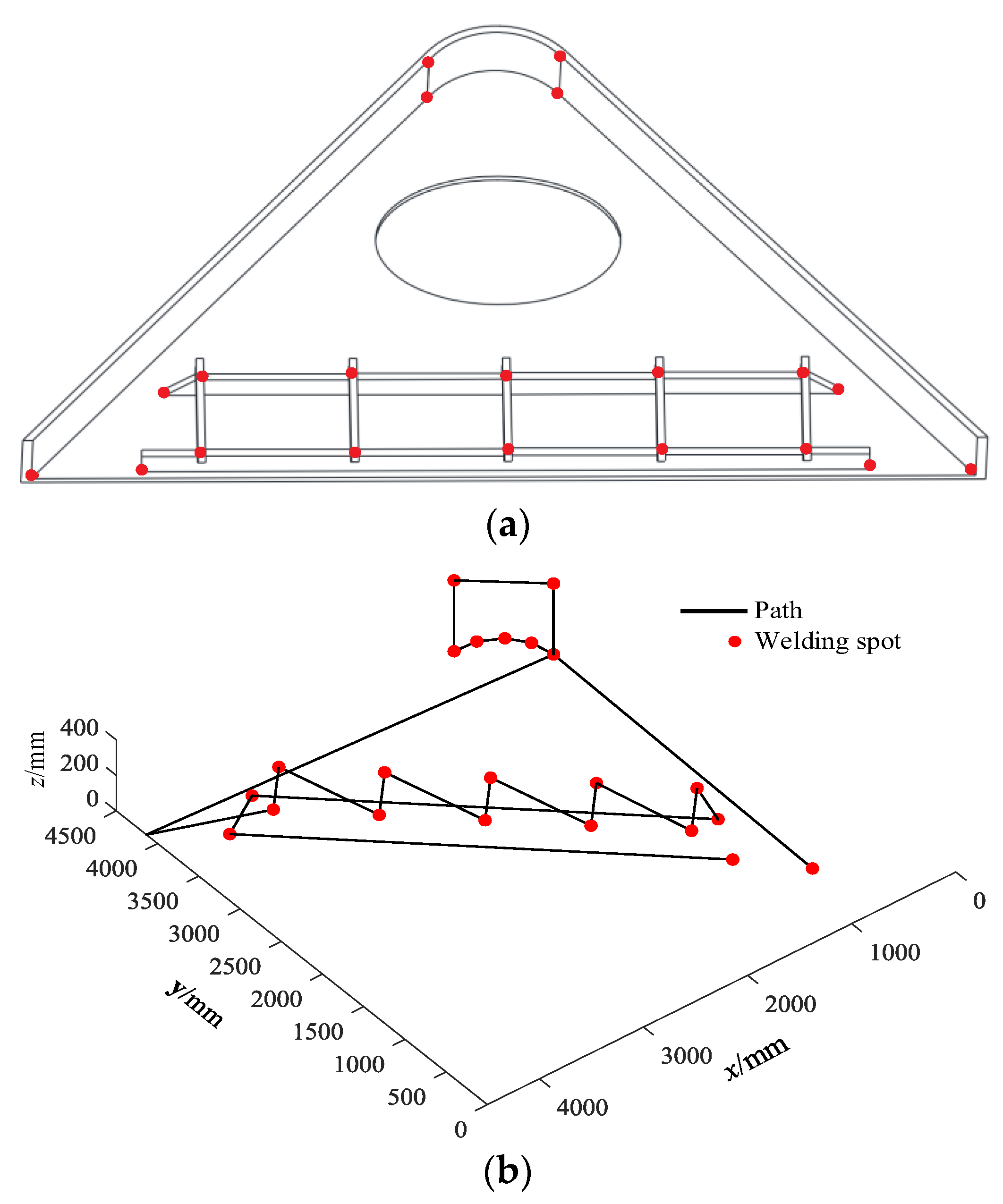
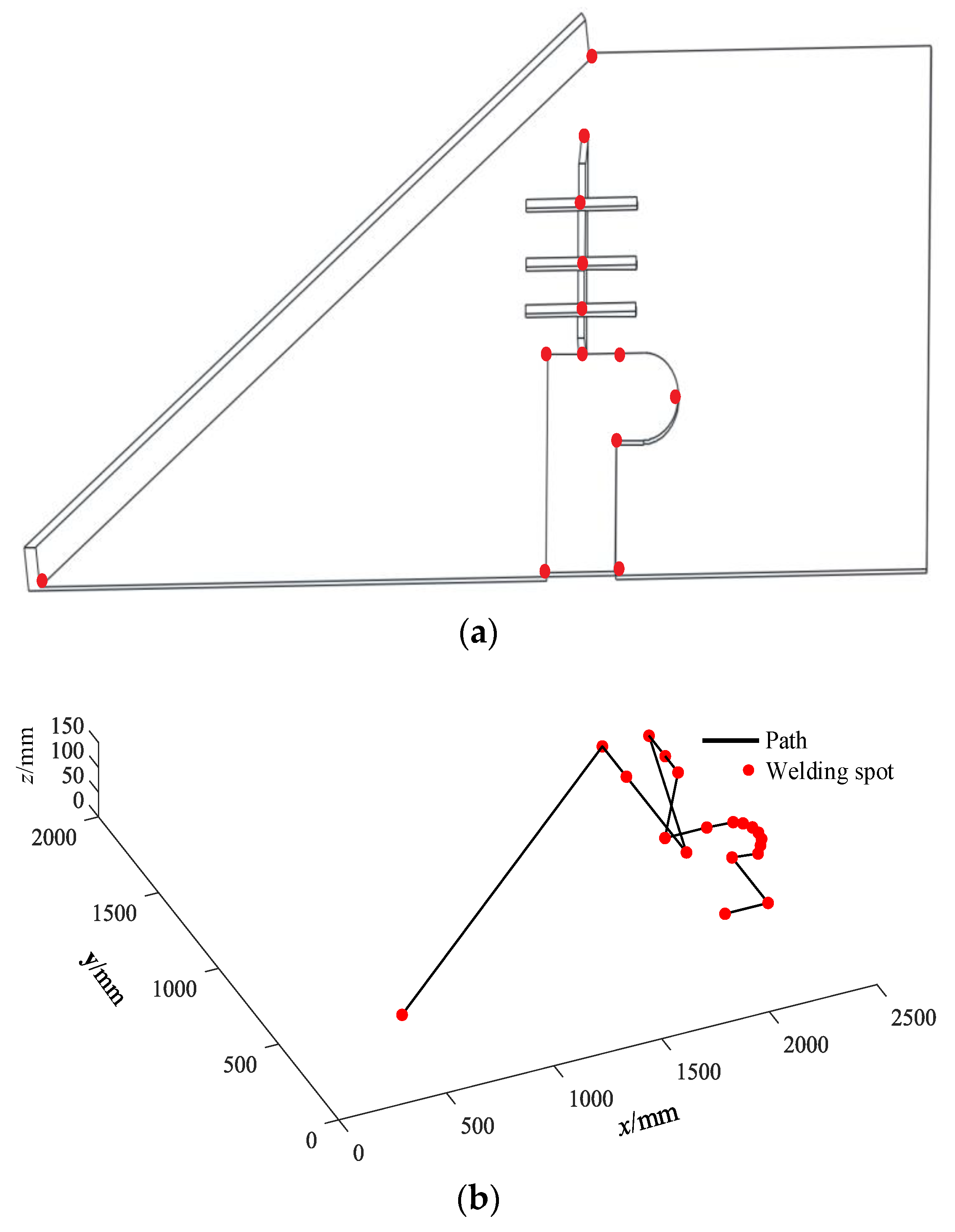
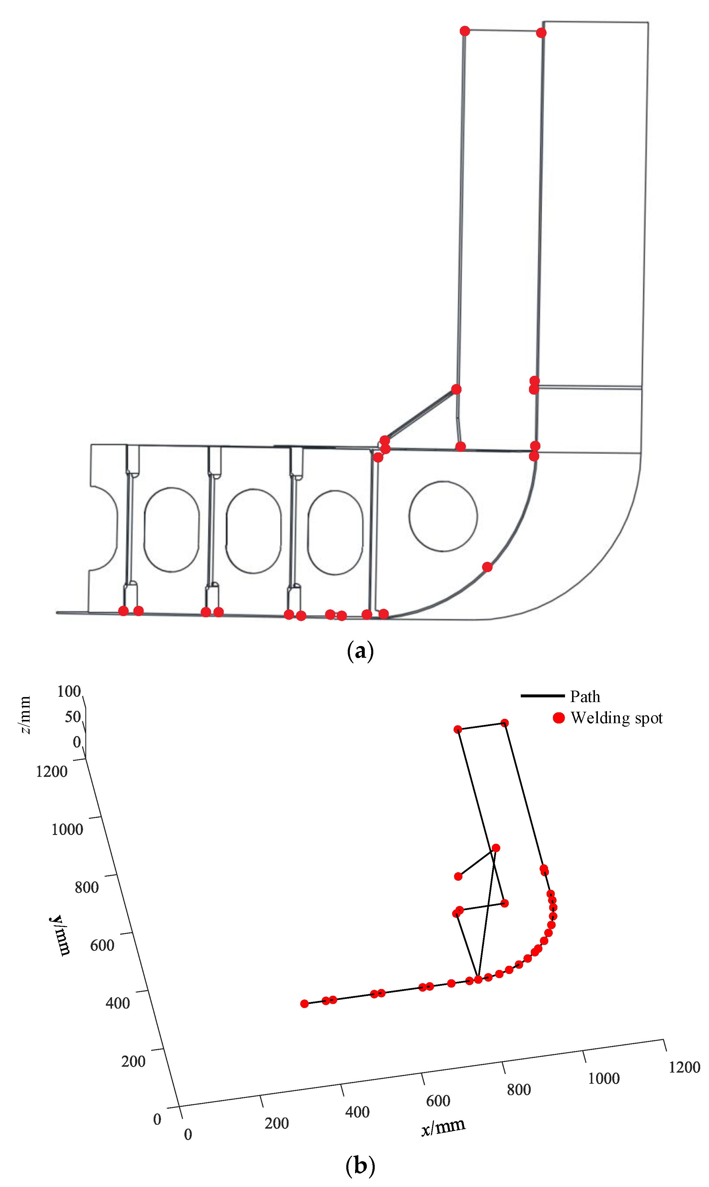
Figure 10, Figure 11 and Figure 12 show the optimal planning results of the other three ship weldments based on the proposed IOACS. Figure 10a, Figure 11a, and Figure 12a show the three-dimensional models of three types of ship weldments and the distribution of welding spots on them. Figure 10b, Figure 11b, and Figure 12b show the planned optimal welding path based on IOACS. From the figure, it can be seen that the multi-objective path planning based on IOACS can realize the optimal planning of the welding robot for the ship weldments, and achieve the expected purpose.

6. Experimental Research on Path Planning of Welding Robot

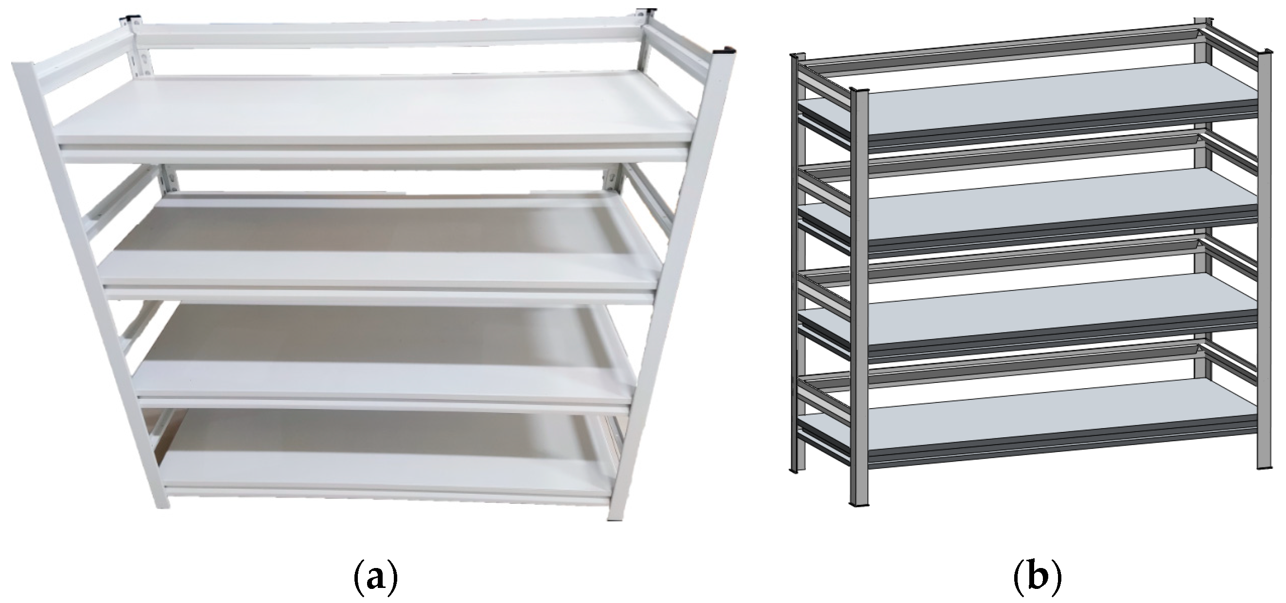
In order to verify the feasibility of the proposed multi-objective immune path planning algorithm in practical application, the path planning and welding simulation experiments were carried out using the Borunte robot in the laboratory with a four-layer shelf as the object.

6.1. Construction of Welding Experiment Platform

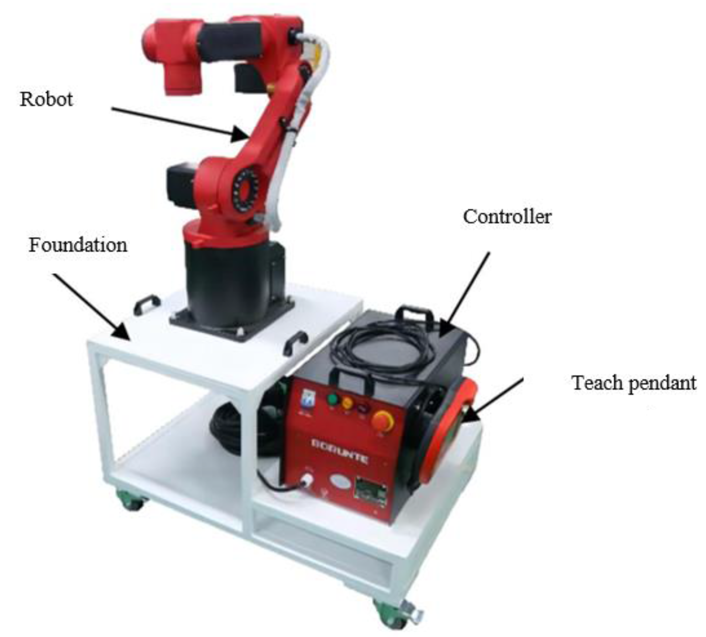
The path planning experimental platform for the welding robot constructed in this paper is shown in Figure 13. The BRTIRUS0805A type Borunte six-axis robot, with a payload of 5 kg, an arm radius of 944 mm, and a power supply of 220 V, is selected as the body of the welding robot. Figure 14 shows a four-layer shelf for the welding object.

6.2. Experiment and Analysis of Path Planning

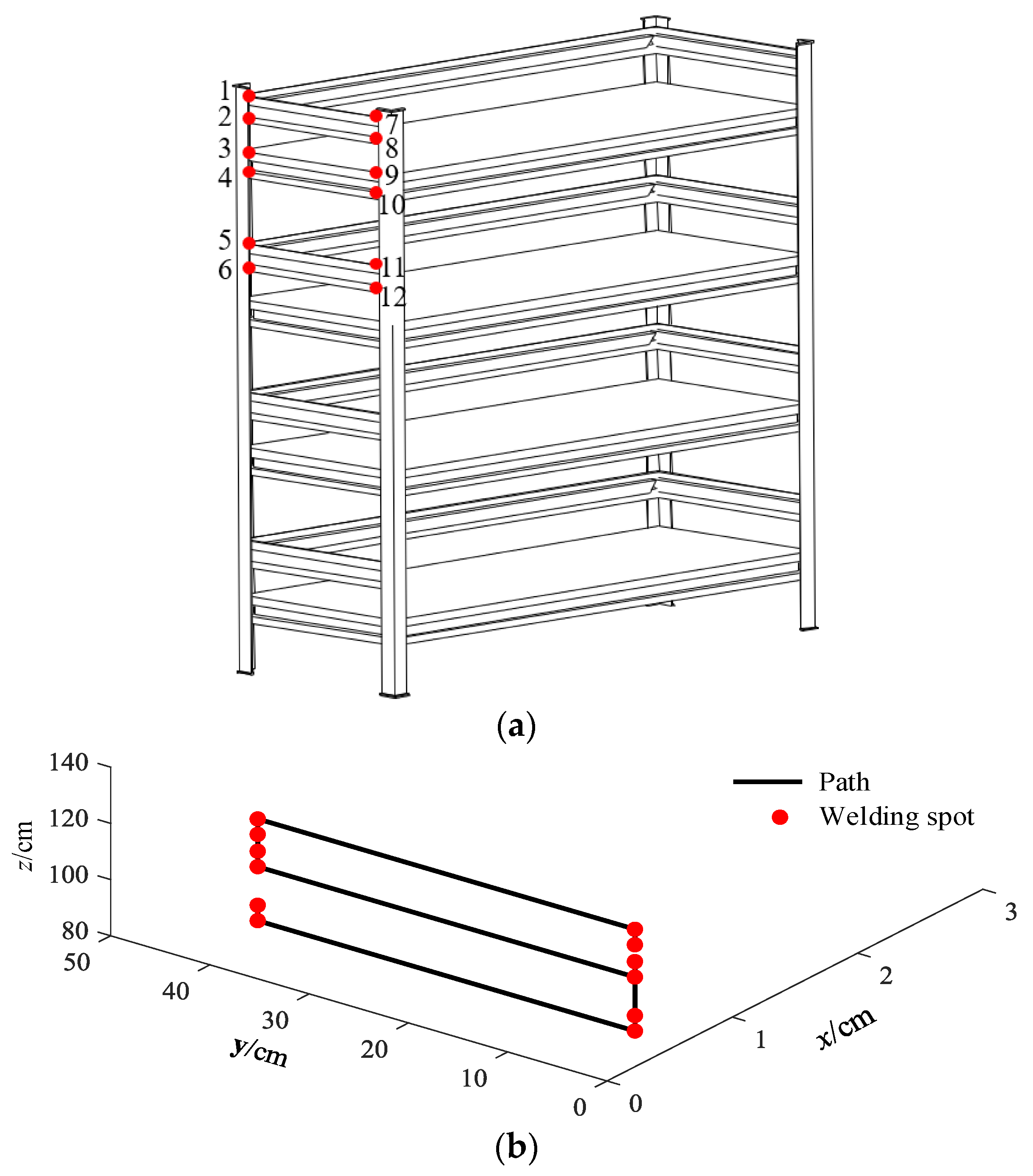
In order to verify the effectiveness of the proposed multi-objective immune path planning algorithm in actual working conditions, the shelf in Figure 14 is taken as the object, and the path planning is carried out for the 12 welding spots on its side (see Figure 15a). The experimental process: firstly, according to the distribution of welding spots on the shelf, the optimal planning path is obtained using the multi-objective immune optimization algorithm based on the length of the planning path and energy consumption: 8 → 7 → 1 → 2 → 3 → 4 → 10 → 9 → 11 → 12 → 6 → 5, as shown in Figure 15b. Then, the robot carries out welding simulations according to the planned path and completes the optimal path, so as to determine that the planned path is feasible without any robot interference and other problems.
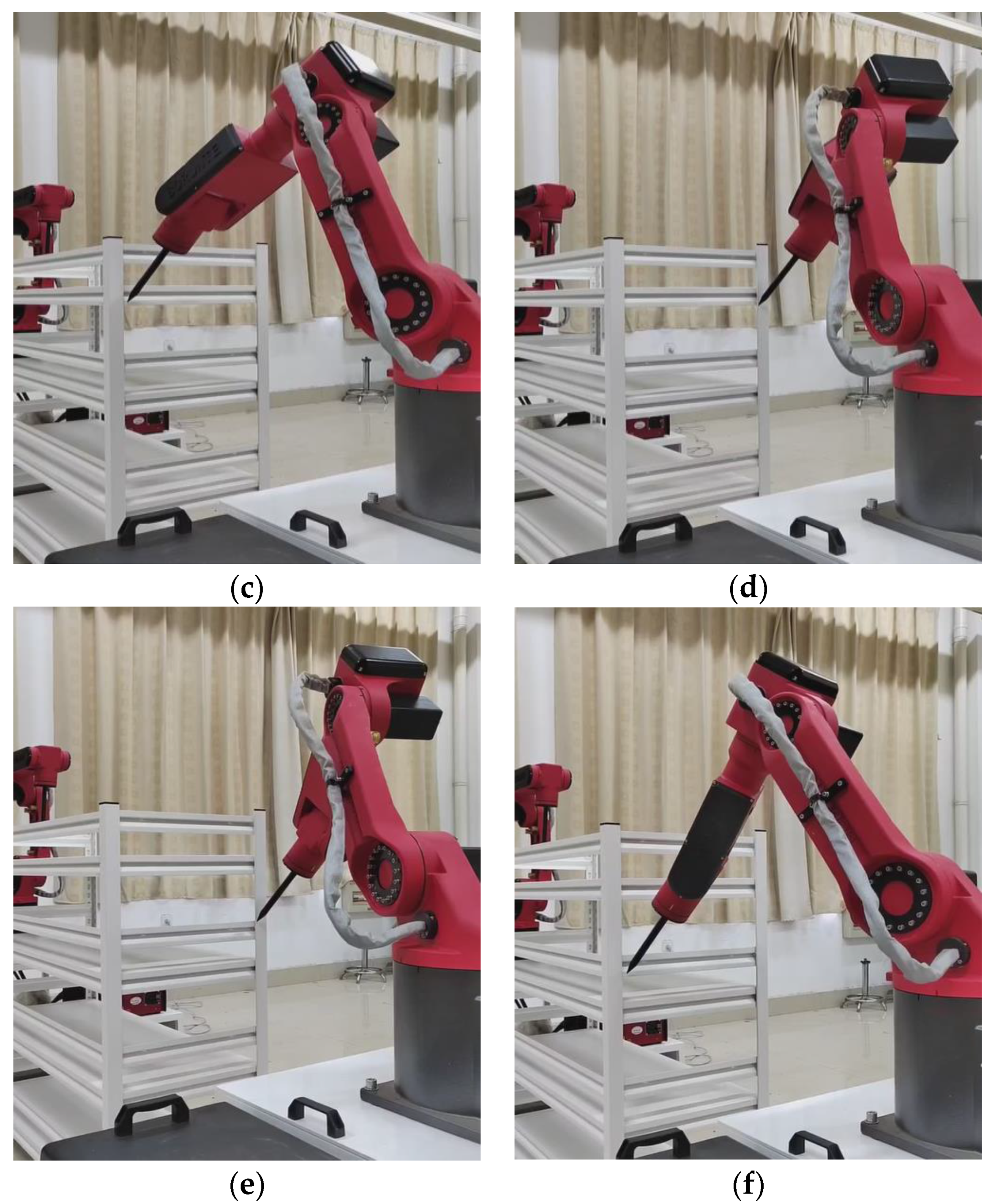
Figure 16 shows the moving process of the robot according to the planned path. Due to the limitation of the experimental conditions and the fact that the robot path planning algorithm does not involve the actual welding operation of the robot, the robot only performs the movement of simulated welding during the whole experiment.
From the experimental process, it can be seen that the robot can simulate the welding task according to the planned path. During the whole process, the robot runs smoothly and the moving path is reasonable, and there are no safety problems such as interference, which verifies the effectiveness of the path planning algorithm in this paper.

7. Discussion

Path planning is the prerequisite for welding robots to realize automatic welding. The performance of path planning also directly determines the welding effect of the robot, so how to improve the accuracy and efficiency of path planning for welding robots has always been the focus of domestic and foreign scholars. From the existing research, it can be seen that the current optimization models constructed for welding robot path planning are relatively one-sided. That is, path optimization is mainly realized based on the length of the welding seam. The spatial movement distance of the welding torch without welding is not considered, and the energy consumption of the welding robot is not considered. The former will make it difficult for the robot to obtain the globally optimal path of the whole process, and the latter will reduce the energy utilization rate of the robot. In view of this, the multi-objective optimization functions for welding robot path planning, including welding path length, welding torch moving distance without welding, and energy loss, are discussed in this paper. In addition, as the number of welding spots on the weldment increases, the number of path schemes for the welding robot will increase exponentially, and it is difficult for traditional optimization algorithms to obtain the globally optimal path. Therefore, for the multi-variable and multi-objective path planning problem of ship welding robots, the immune optimization algorithm based on cluster analysis and self-circulation (IOACS) is introduced in this paper.
For four ship weldments, the comparison results of seven algorithms (namely, SGA, IGA, ACO, IOACS, ABC, PSO, and ICO) show that, on the one hand, the self-circulation strategy of IOACS ensures the diversity of the population, prevents the path planning algorithm from falling into a local minimum, and improves the global path planning ability of the welding robot; on the other hand, the multi-objective optimization function based on the fusion of path length and energy consumption can reduce the energy consumption of the robot while ensuring that the path length is shortened. The test comparison of different weldments verifies the effectiveness and superiority of the proposed path planning algorithm.
The path planning research in this paper is carried out on the premise that the coordinates of the welding spots on the weldment are known. Therefore, before the path planning of the welding robot, it is necessary to extract the welding seam and welding spot coordinates on the weldment through welding seam recognition and parameter extraction techniques [37,38], which is a prerequisite for the welding robot to use the proposed path planning algorithm directly, and it is also a limitation of the algorithm.

8. Conclusions and Future Work

In order to improve the welding efficiency of the ship welding robot, a multi-objective optimization function for the path planning of the robot is constructed in this paper, and a new immune evolution algorithm is introduced to realize the global optimization of the path. Through theoretical analysis and numerical tests, the following conclusions can be drawn:
  • According to the working characteristics of the ship welding robot, the length objective function including the welded seam path and the moving path of the welding torch without welding is constructed, which avoids the optimal path search based on a single seam and realizes the path length optimization in the whole working process of the welding robot;
  • Based on the dynamic analysis of the welding robot, the energy loss objective function for the path planning of the welding robot is constructed based on the Lagrange equation, which helps to improve the energy utilization rate of the welding robot, reduce joint wear and improve the welding accuracy;
  • The multi-objective path planning function of the welding robot is constructed by fusing the path length and energy loss, taking into account the efficiency and cost of the robot operation. At the same time, the global optimization of the welding path is realized through the immune algorithm based on clustering analysis and self-circulation, which improves the optimization accuracy, efficiency, and stability of the path planning algorithm and shows the effectiveness and superiority of the path planning algorithm in this paper.
At present, the proposed multi-objective immune optimization algorithm is mainly suitable for the path planning of a single welding robot. With the continuous development of intelligent manufacturing and the complexity of welding tasks, multi-robot collaborative welding will be the main application trend. Different from the work of a single welding robot, the working ability and working position of each welding robot need to be considered when planning the path of multiple welding robots. That is to say, before the path planning, it is necessary to establish the welding spot allocation model of the welding robot. The future work will focus on the optimal distribution of welding spots and the optimal path planning of multiple welding robots under multiple constraints, so as to further broaden the application scope of welding robots.

Author Contributions

Methodology, Y.S. and Y.G.; validation, M.Y., H.S. and Z.G.; original draft preparation, Y.S. and Y.G.; writing, Y.S. and M.Y. All authors have read and agreed to the published version of the manuscript.

Funding

This research was funded by the High-Tech Ship Scientific Research Project from the Ministry of Industry and Information Technology ([2019]360), and the 2022 Industry-University Research Pre-Research Fund Project of Zhangjiagang City (ZKYY2233).

Data Availability Statement

Not applicable.

Conflicts of Interest

The authors declare no conflict of interest.

References

  1. Khajehzadeh, M.; Taha, M.R.; Elshafie, A.; Eslami, M. Search for critical failure surface in slope stability analysis by gravitational search algorithm. Int. J. Phys. Sci. 2011, 6, 5012–5021. [Google Scholar]
  2. Eslami, M.; Shareef, H.; Mohamed, A.; Khajehzadeh, M. Damping controller design for power system oscillations using hybrid GA-SQP. Int. Rev. Elec. Eng. 2011, 6, 888–896. [Google Scholar] [CrossRef]
  3. Eslami, M.; Shareef, H.; Mohamed, A.; Khajehzadeh, M. PSS and TCSC damping controller coordinated design using GSA. Energy Procedia 2012, 14, 763–769. [Google Scholar] [CrossRef]
  4. Eslami, M.; Shareef, H.; Mohamed, A. Optimization and coordination of damping controls for optimal oscillations damping in multi-machine power system. Int. Rev. Electr. Eng. 2011, 6, 1984–1993. [Google Scholar] [CrossRef]
  5. Wang, T.; Xue, Z.L.; Dong, X.Q.; Xie, S. Autonomous intelligent planning method for welding path of complex ship components. Robotica 2020, 39, 428–437. [Google Scholar] [CrossRef]
  6. Nie, F.; Zhao, Z.H. Path planning of welding robot based on changing step fruit fly optimization algorithm. Manuf. Technol. Mach. Tool 2021, 11, 21–25. [Google Scholar] [CrossRef]
  7. Xue, L.K.; Wang, X.W.; Gu, X.S. Welding robot path planning based on DTC-MOPSO algorithm. Inf. Control 2016, 45, 713–721. [Google Scholar] [CrossRef]
  8. Wang, X.W.; Shi, Y.P.; Yan, Y.X.; Gu, X.S. Intelligent welding robot path optimization based on discrete elite PSO. Soft Comput. 2016, 21, 5869–5881. [Google Scholar] [CrossRef]
  9. Yao, J.Y.; Wu, F.Y. Research on path planning method for welding robot based on improved bee colony algorithm. Mach. Tool Hydraul. 2019, 47, 49–52. [Google Scholar] [CrossRef]
  10. Gao, Y.; Zhang, Y.W. Path optimization of welding robot based on ant colony and genetic algorithm. J. Appl. Math. 2022, 12, 3608899. [Google Scholar] [CrossRef]
  11. Wang, Q.Y.; Sun, Y.K.; Tang, Q.C.; Ma, L.; Zhao, D.; Yang, J.P.; Xu, J. A dual-robot cooperative welding path planning algorithm based on improved ant colony optimization. In Proceedings of the 6th IFAC Symposium on Telematics Applications TA 2022, Nancy, France, 15–17 June 2022; pp. 7–12. [Google Scholar] [CrossRef]
  12. Zhang, B.C.; Wu, C.; Pang, Z.X.; Li, Y.; Wang, R.K. Hybrid global optimum beetle antennae search—Genetic algorithm based welding robot path planning. In Proceedings of the 9th Annual International Conference on CYBER Technology in Automation, Control, and Intelligent Systems, Suzhou, China, 29 July–2 August 2019; pp. 1520–1524. [Google Scholar] [CrossRef]
  13. Xu, Z.F.; Liu, L.L.; Zou, W.; Xu, T.; Yuan, S.B. Multi robot welding path planning based on improved ant colony algorithm. In Proceedings of the 11th International Workshop of Advanced Manufacturing and Automaiton, Zhengzhou, China, 11–12 October 2021; pp. 198–206. [Google Scholar] [CrossRef]
  14. Machmudah, A.; Parman, S.; Abbasi, A.; Solihin, M.I.; Manan, T.S.A.; Beddu, S.; Ahmad, A.; Rasdi, N.W. Cyclic path planning of hyper-redundant manipulator using whale optimization algorithm. Int. J. Adv. Comput. Appl. 2021, 12, 677–686. [Google Scholar] [CrossRef]
  15. Fang, Z.; Liang, X. Intelligent obstacle avoidance path planning method for picking manipulator combined with artificial potential field method. Ind. Robot 2022, 49, 835–850. [Google Scholar] [CrossRef]
  16. Li, X.J.; Liu, H.S.; Dong, M.H. A general framework of motion planning for redundant robot manipulator based on deep reinforcement learning. IEEE Trans. Ind. Inform. 2022, 18, 5253–5263. [Google Scholar] [CrossRef]
  17. Miao, C.W.; Chen, G.Z.; Yan, C.L.; Wu, C.L. Path planning optimization of indoor mobile robot based on adaptive ant colony algorithm. Comput. Ind. Eng. 2021, 56, 107230. [Google Scholar] [CrossRef]
  18. Tan, Z.; Liang, H.G.; Zhang, D.; Wang, Q.G. Path planning of surgical needle: A new adaptive intelligent particle swarm optimization method. Trans. Inst. Meas. Control. 2022, 44, 766–774. [Google Scholar] [CrossRef]
  19. Hu, X.B.; Deng, X. A gantry robot system for cutting single y-shaped welding grooves on plane workpieces. Proc. Inst. Mech. Eng. Part E J. Process Mech. Eng. 2021, 235, 45–59. [Google Scholar] [CrossRef]
  20. Wang, X.W.; Tang, B.; Gu, X.S. Research on obstacle avoidance strategy for welding robot. J. Mech. Eng. 2019, 55, 77–84. [Google Scholar] [CrossRef]
  21. Wang, W.; Wei, D.D.; Li, L.M. Research on collaborative modeling and obstacle avoidance control for humanoid dual manipulator. Comput. Simul. 2018, 35, 299–305. [Google Scholar] [CrossRef]
  22. Qiu, B.; Shan, L.; Chang, L.; Wang, Z.Q.; Qu, Y. Collision avoidance path planning of dual manipulators based on bidirectional planning of improved artificial potential field method. J. Jiangsu Univ. Sci. Technol. 2021, 35, 72–79. [Google Scholar]
  23. Rout, A.; Bbvl, D.; Biswal, B.B. Optimal trajectory generation of an industrial welding robot with kinematic and dynamic constraints. Ind. Robot 2020, 47, 68–75. [Google Scholar] [CrossRef]
  24. Teng, Y.J.; Chen, W.J.; Yang, T.Y.; Jing, Z.L.; Liu, W.Y. Dynamics analysis of flexible manipulator driven by SMA spring. J. Shanghai Jiaotong Univ. 2021, 55, 1018–1026. [Google Scholar] [CrossRef]
  25. Zhang, Z.W.; Wu, L.H.; Zhang, W.Q.; Tao, P.; Jun, Z. Energy-efficient path planning for a single-load automated guided vehicle in a manufacturing workshop. Comput. Ind. Eng. 2021, 158, 107397. [Google Scholar] [CrossRef]
  26. Shen, Y.; Liu, S.D.; Yuan, M.X.; Dai, X.L.; Lan, J.C. Immune optimization of double-sided welding sequence for medium-small assemblies in ships based on inherent strain method. Metals 2022, 12, 1091. [Google Scholar] [CrossRef]
  27. Yuan, M.X.; Jiang, Y.F.; Hua, X.B.; Wang, B.B.; Shen, Y. A real-time immune planning algorithm incorporating a specific immune mechanism for multi-robots in complex environments. Proc. Inst. Mech. Eng. Part I J. Syst. Control Eng. 2017, 23, 29–42. [Google Scholar] [CrossRef]
  28. Stogiannos, M.; Alexandridis, A.; Sarimveis, H. An enhanced decentralized artificial immune-based strategy formulation algorithm for swarms of autonomous vehicles. Appl. Soft Comput. 2020, 89, 106135. [Google Scholar] [CrossRef]
  29. Gao, Y.Q.; Shen, Y.; Yang, Z.; Chen, D.P.; Yuan, M.X. Immune optimization algorithm for traveling salesman problem based on clustering analysis and self-circulation. In Proceedings of the 3rd International Conference on Advanced Information Science and System, Sanya, China, 26–28 November 2021; pp. 48–54. [Google Scholar] [CrossRef]
  30. Chen, T.G.; Shi, J.W.; Yang, J.J. Enhancing network cluster synchronization capability based on artificial immune algorithm. Hum.-Cent. Comput. Inf. Sci. 2019, 9, 11–19. [Google Scholar] [CrossRef]
  31. Sun, B.; Jiang, P.; Zhou, G.R.; Dong, D.Y. AGV optimal path planning based on improved genetic algorithm. Comput. Eng. Des. 2020, 41, 550–556. [Google Scholar]
  32. Lou, G.X.; Cai, Z.Y. Improved hybrid immune clonal selection genetic algorithm and its application in hybrid shop scheduling. Cluster Comput. 2019, 22, 3419–3429. [Google Scholar] [CrossRef]
  33. Wang, Y.; Han, Z.P. Ant colony optimization for traveling salesman problem based on parameters optimization. Appl. Soft Comput. 2021, 107, 107439. [Google Scholar] [CrossRef]
  34. Yang, Y.; Luo, K. An artificial bee colony algorithm based on improved search strategy. In Proceedings of the 2nd International Conference on Artificial Intelligence and Information Systems, Chongqing, China, 28 May 2021; pp. 1–4. [Google Scholar] [CrossRef]
  35. Ahmed, N.; Pawase, C.J.; Chang, K.H. Distributed 3-D path planning for multi-UAVs with full area surveillance based on particle swarm optimization. Appl. Sci. 2021, 11, 3417. [Google Scholar] [CrossRef]
  36. Shen, Y.; Yuan, M.X.; Wang, Q. Viros evolutionary immune clonal algorithm for optimization of manipulator. Comput. Eng. Appl. 2011, 47, 224–226. [Google Scholar] [CrossRef]
  37. Dai, X.L.; Shen, Y.; Cao, R.X.; Sun, H.W.; Yuan, M.X. Feature recognition of ship welding seam based on triangulation and contour analysis. Sci. Technol. Eng. 2022, 22, 12491–12498. [Google Scholar]
  38. Yuan, M.X.; Dai, X.L.; Liu, C.; Sun, H.W.; Wang, L. Feature parameters extraction of ship welds based on spatial position and contour distance. Trans. China Weld. Inst. 2023, 22, 84–92. [Google Scholar] [CrossRef]
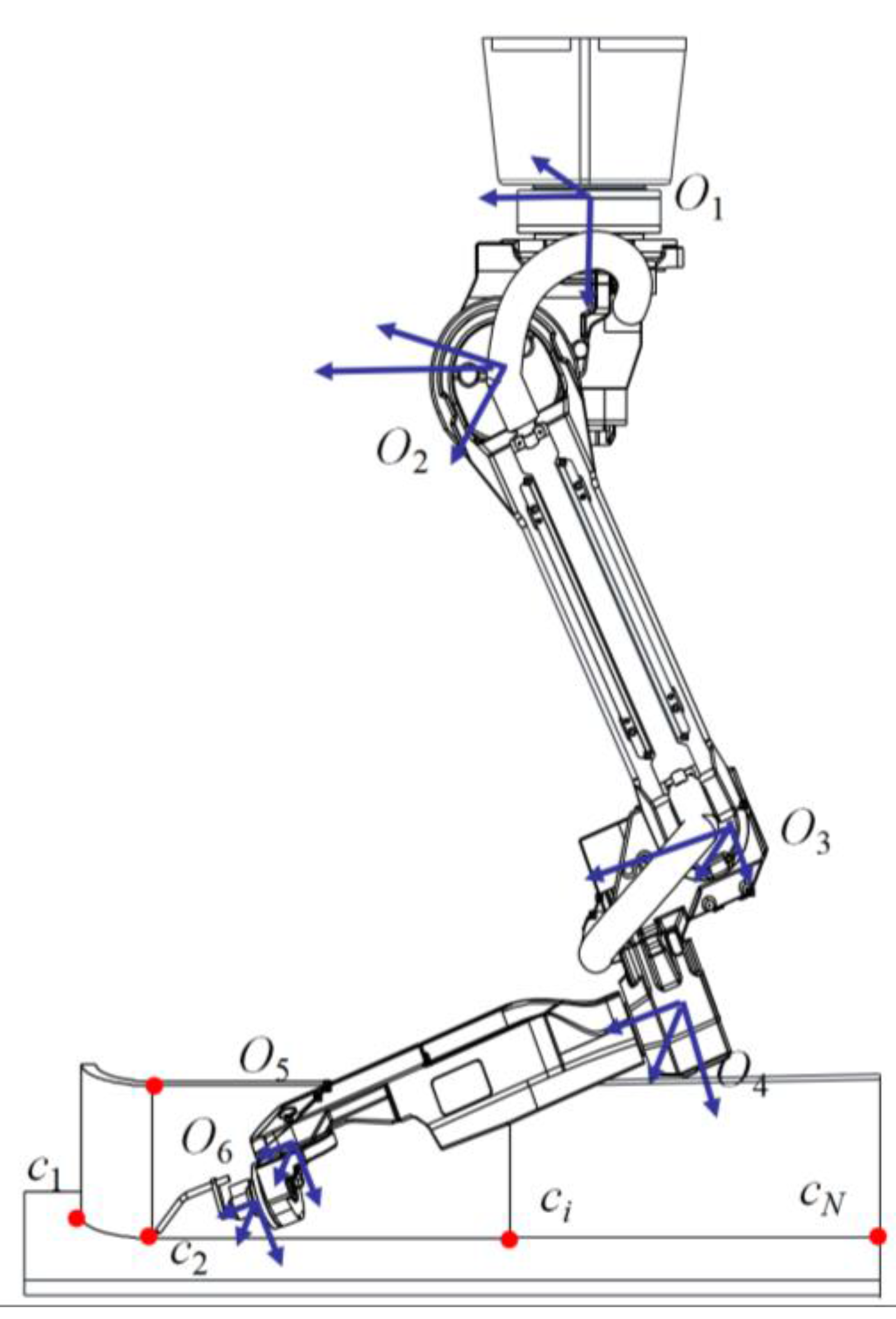
Figure 1. Schematic diagram of path planning for ship welding robot.
Electronics 12 02040 g001
Figure 2. Robot environment modeling.
Electronics 12 02040 g002
Figure 3. Planning example without welding.
Electronics 12 02040 g003
Figure 4. Schematic diagram of self-circulation crossover [29].
Electronics 12 02040 g004
Figure 5. Four types of ship weldments: (a) Side plate weldment; (b) Inner bottom plate weldment; (c) Bilge plate weldment; (d) Base plate weldment.
Electronics 12 02040 g005aElectronics 12 02040 g005b
Figure 6. Distribution and labeling of welding spots on the base plate weldment.
Electronics 12 02040 g006
Figure 7. Environmental modeling and path plan of the base plate weldment.
Electronics 12 02040 g007
Figure 8. Planning comparison among seven algorithms for the base plate weldment: (a) IOACS; (b) ACO; (c) IGA; (d) SGA; (e) ABC; (f) PSO; (g) ICO.
Electronics 12 02040 g008aElectronics 12 02040 g008bElectronics 12 02040 g008c
Figure 9. Evolutionary curves of seven planning algorithms for the bilge plate weldment: (a) Path length; (b) Energy consumption.
Electronics 12 02040 g009
Figure 10. Path planning for welding spots on the side plate weldment: (a) Distribution of spots to be welded; (b) Optimal planning path based on IOACS.
Electronics 12 02040 g010
Figure 11. Path planning for welding spots on the inner bottom plate weldment: (a) Distribution of spots to be welded; (b) Optimal planning path based on IOACS.
Electronics 12 02040 g011
Figure 12. Path planning for welding spots on the bilge plate weldment: (a) Distribution of spots to be welded; (b) Optimal planning path based on IOACS.
Electronics 12 02040 g012
Figure 13. Borunte robot.
Electronics 12 02040 g013
Figure 14. Four-layer shelf: (a) The physical object of the shelf; (b) 3D image of the shelf.
Electronics 12 02040 g014
Figure 15. Planning of welding spots on shelf based on IOACS: (a) Distribution of welding spots on shelf; (b) Planning results of welding spots on shelf.
Electronics 12 02040 g015
Figure 16. Simulated welding process of the shelf: (a) The 1st sequential welding spot (that is, the original spot 8); (b) The 4th sequential welding spot (that is, the original spot 2); (c) The 6th sequential welding spot (that is, the original spot 4); (d) The 8th sequential welding spot (that is, the original spot 9); (e) The 9th sequential welding spot (that is, the original spot 11); (f) The 12th sequential welding spot (that is, the original spot 5).
Electronics 12 02040 g016aElectronics 12 02040 g016b
Table 1. Performance comparison of planning length among seven algorithms.
Ship WeldmentsPerformance IndexSGAIGAACOIOACS
Side plate weldmentLength/mmMinimum5107.164936.114801.074698.33
Average5832.975371.615071.134869.34
Standard deviation112.1380.8978.8229.83
Inner bottom plate weldmentLength/mmMinimum2091.351879.311806.181791.12
Average2310.171977.321910.111832.29
Standard deviation65.9347.2959.6124.98
Bilge plate weldmentLength/mmMinimum3521.193237.843018.192869.22
Average3697.173431.913077.332981.39
Standard deviation64.2343.2251.6225.22
Base plate weldmentLength/mmMinimum5239.174896.254783.664633.15
Average5362.715217.535007.324818.22
Standard deviation109.3171.1172.727.31
Ship WeldmentsPerformance IndexABCPSOICO
Side plate weldmentLength/mmMinimum4931.404975.214731.05
Average5402.645569.334932.61
Standard deviation81.4291.9335.42
Inner bottom plate weldmentLength/mmMinimum1869.441971.421801.21
Average2013.212108.261899.15
Standard deviation49.3453.1234.23
Bilge plate weldmentLength/mmMinimum3269.403348.412938.26
Average3376.373578.163057.43
Standard deviation44.5752.3436.28
Base plate weldmentLength/mmMinimum5041.274806.174702.41
Average5302.185116.434936.24
Standard deviation88.7468.9451.48
Table 2. Performance comparison of energy consumption performance among seven algorithms.
Ship WeldmentsPerformance IndexSGAIGAACOIOACS
Side plate weldmentEnergy consumption/KJMinimum8.077.387.177.03
Average8.657.717.427.19
Standard deviation0.690.430.360.29
Inner bottom plate weldmentEnergy consumption/KJMinimum4.924.534.674.47
Average5.625.214.994.76
Standard deviation0.630.580.450.42
Bilge plate weldmentEnergy consumption/KJMinimum6.435.825.485.26
Average7.416.976.536.39
Standard deviation1.621.411.291.46
Base plate weldmentEnergy consumption/KJMinimum8.617.667.216.99
Average8.417.787.277.13
Standard deviation0.390.270.290.23
Ship WeldmentsPerformance IndexABCPSOICO
Side plate weldmentEnergy consumption/KJMinimum7.297.947.12
Average7.658.417.34
Standard deviation0.410.540.37
Inner bottom plate weldmentEnergy consumption/KJMinimum4.434.944.60
Average5.355.534.82
Standard deviation0.540.620.46
Bilge plate weldmentEnergy consumption/KJMinimum5.886.135.30
Average7.097.046.42
Standard deviation1.551.521.49
Base plate weldmentEnergy consumption/KJMinimum7.248.037.14
Average7.758.287.30
Standard deviation0.280.310.22
Table 3. Performance comparison of planning efficiency among seven algorithms.
Ship WeldmentsPerformance IndexSGAIGAACOIOACS
Side plate weldmentConvergence generationMinimum766637601267
Average872.71731.52694.41510.48
Standard deviation109.3277.4382.3330.12
Inner bottom plate weldmentConvergence generationMinimum498421376159
Average529.43487.32402.23344.27
Standard deviation67.1547.3252.5127.11
Bilge plate weldmentConvergence generationMinimum511487456177
Average577.80529.12497.15402.92
Standard deviation71.1246.7353.6626.11
Base plate weldmentConvergence generationMinimum723605540180
Average832.81701.74664.22441.91
Standard deviation97.1774.1877.4430.53
Ship WeldmentsPerformance IndexABCPSOICO
Side plate weldmentConvergence generationMinimum615715421
Average714.63792.40533.41
Standard deviation79.4389.4344.23
Inner bottom plate weldmentConvergence generationMinimum416463226
Average492.30503.64401.35
Standard deviation45.2848.3235.69
Bilge plate weldmentConvergence generationMinimum481504237
Average543.25562.53396.46
Standard deviation56.3866.3734.69
Base plate weldmentConvergence generationMinimum613684.35413
Average743.69710.65592.34
Standard deviation69.8484.3644.94
Table 4. Coordinates of welding spots on the base plate weldment.
Numberx/mmy/mmz/mmNumberx/mmy/mmz/mm
11039.91864.10124940.91382.20
21646.1686.50135298.92180.60
32797.11421.30145105.5832.60
42747.32369.90155505.71868.80
53765.32186.60162747.32369.9300
64370.11690.60172797.11421.3300
74646.52265.30183765.32186.6300
84370.11637.90194370.11637.9300
94250.81413.30204250.81413.3300
104250.81002.70214370.11690.6200
114681.4802.70224940.91382.2200
Disclaimer/Publisher’s Note: The statements, opinions and data contained in all publications are solely those of the individual author(s) and contributor(s) and not of MDPI and/or the editor(s). MDPI and/or the editor(s) disclaim responsibility for any injury to people or property resulting from any ideas, methods, instructions or products referred to in the content.