Article

Apple-Picking Robot Picking Path Planning Algorithm Based on Improved PSO

1
College of Metrology and Measurement Engineering, China Jiliang University, Hangzhou 310018, China
2
Engineering Training Center, China Jiliang University, Hangzhou 310018, China
3
Faculty of Mechanical Engineering & Automation, Zhejiang Sci-Tech University, Hangzhou 310018, China
*
Author to whom correspondence should be addressed.
Electronics 2023, 12(8), 1832; https://doi.org/10.3390/electronics12081832
Submission received: 3 March 2023 / Revised: 9 April 2023 / Accepted: 10 April 2023 / Published: 12 April 2023
(This article belongs to the Special Issue Autonomous Robots and Systems)

Abstract

:
To solve the problem that the robot often collides with the obstacles such as branches around the fruit during picking due to its inability to adapt to the fruit growing environment, this paper proposes an apple-picking robot picking path planning algorithm based on the improved PSO. The main contents of the algorithm are: firstly, the fruit and its surrounding branches are extracted from the 3D point cloud data, and the picking direction of the fruit is calculated; then the point cloud on the surface of the fruit and branches is used to establish the spatial model of obstacles; finally, an improved particle swarm optimization (PSO) algorithm is proposed to plan the obstacle avoidance trajectory of the end-effector in space, which can dynamically adjust the velocity weights according to the trend of the particle fitness value and the position of the particle swarm center of mass. The experimental results show that the improved PSO has faster convergence speed than the standard PSO, and the path planning method proposed in this paper improves the fruit-picking success rate to 85.93% and reduces the picking cycle to 12 s. This algorithm can effectively reduce the collision between the manipulator and branches during apple picking and improve the picking success rate and picking efficiency.

1. Introduction

Agricultural technology has been rapidly enhanced with emerging technologies such as robotics, artificial intelligence, and machine vision [1,2]. At the same time, there has been a major development of agricultural robots with autonomous intelligent functions [3]. In recent years there has been an urgent need for apple-picking robots to be involved in the picking process because of the increasing production of apples and the problem of higher labor costs. Currently, apple-picking robots have more mature technology in the field of fruit detection, positioning, and spot picking. However, there are still many areas that need to be improved, such as in unstructured orchards with different fruit growth postures, the picking mechanism cannot have a reasonable posture to grasp the fruit, and the cluttered branches distributed around the target fruit can cause interference to the robot performing the picking work. These factors can cause damage to the fruit, the fruit tree, or the robot [4], causing economic losses and reducing the success rate of fruit picking. The need for manual involvement to bring the system back into operation after a collision is also costly in terms of labor and can reduce picking efficiency. Therefore the main objective of this paper is to calculate the growth attitude of each fruit on the fruit tree through the vision algorithm under the existing apple-picking robot system, to facilitate the grasping of the end-effector, to be able to extract the branches around the target fruit, and to calculate a path that can avoid the collision between the end of the robot and the branches through the path planning algorithm, so that the apple-picking robot has the function of autonomous planning of the picking path, to achieve the purpose of improving the success rate of fruit picking and reducing economic losses.
Depending on the location of the camera in the system, apple-picking robots can be divided into two categories: one with a camera at the end of the robot that can guide the robot through the picking process, and the other with a camera mounted outside the robot that takes a global shot and then the robot performs the picking work [5]. At present, the first type of system in fruit picking, mainly through the camera located at the end of the robot to continuously obtain images of the fruit, is the real-time adjustment of the robot movement attitude so that the end of the actuator reaches the target position to perform the picking action.
Among others, Barth et al., studied an automatic pepper-picking robot in a greenhouse [6,7], which captures the position of the center of the pepper and the position of the main pole using a camera located at the end of the manipulator. According to the angle formed by the center of the camera, the main pole, and the fruit, the attitude of the manipulator is adjusted so that the end-effector can accurately reach the cutting point, improving the success rate of picking, but there is the problem of low picking efficiency.
Kang et al., developed an autonomous apple-picking robot with adjustable picking attitude [8,9]. The system is equipped with two 3D cameras, one located on the mobile platform for global fruit search and localization, and the other at the end of the manipulator to adjust the fruit-picking attitude. In this system, the fruit-picking direction is the direction of the line between the center of mass of the visible point cloud on the fruit surface and the center of the fruit [10], and the robot approaches the target fruit in this direction to reduce the probability of collision and make the system have certain adaptive capabilities, but there are problems of high cost and low efficiency.
Chen et al., combined the visual servo control method with an improved fuzzy neural network sliding mode control algorithm to eliminate sliding mode jitter and improve the stability of the control system according to the characteristics of the motion control of apple-picking robots [11] and applied the algorithm to the field of agricultural-product-picking robots to improve the picking speed of apple-picking robots, but its obstacle avoidance capability was weak. There are also some research results in picking systems where the camera is located outside the manipulator.
Zhao et al., developed a binocular-vision-based two-arm collaborative tomato-picking robot [12], which locates the state of the fruit and branches through the camera and completes the fruit-picking work through the cooperation of the two arms, which can improve the success rate of fruit picking, but the system is more complex and less efficient.
Lin et al., designed an automatic guava-picking robot [13], which obtains the position of the fruit and extracts all the branches through a 3D camera, calculates the closest point on the branch to the fruit, uses the direction of the line connecting this point to the center of mass of the fruit as the picking direction of the fruit, and uses this direction to plan the picking path of the robot, which can reduce the probability of the end-effector catching the branch. Their proposed concept of fruit-picking direction can provide a safer picking direction for fruits with obscure axial characteristics, but not all the branches from the calculation contribute to the calculation, and there is the problem of low efficiency of the algorithm.
Eleni et al., developed an autonomous grape-harvesting robot [14] and proposed a torque-based collision avoidance strategy [15] to avoid collisions in the comp, lex working environments, i.e., a method to determine whether a collision has occurred by detecting whether the force on each joint of the manipulator is abnormal, which functions to return the manipulator to a safe position when a collision occurs and does not provide an effective method of obstacle avoidance.
Zhang et al., proposed an improved artificial potential field method (APF) [16] to solve the obstacle avoidance problem of a two-armed robot. The correctness and effectiveness of the method were verified by simulation. The obstacles in this system are robots whose model parameters can be calculated from their motion states and do not have the function of sensing external unstructured obstacles.
Table 1 shows a comparison of the above fruit and vegetable-picking robots. Different fruits have different levels of environmental complexity. For apples with more complex growth environments, the assistance of multiple cameras can improve obstacle avoidance, but this will increase the cost. The guava-picking method has a high obstacle avoidance capability, and its cost is not high, which can provide ideas for the control of apple-picking robots.
Inspired by the above studies, this paper uses an existing automatic apple-picking robot as an experimental platform. It also proposes a method to calculate the fruit-picking path based on the position of the fruit and the obstacles around the fruit using an improved PSO algorithm. In this approach, first, the concept of using the direction of the shortest continuous line between the fruit and its surrounding branches as the direction of fruit picking is proposed, and its calculation process is briefly described. Afterwards, the other fruits and branches around the target fruit are considered obstacles, and the obstacles are modeled by reducing the fruit to a sphere and the branches to a parallel hexahedron. The proposed PSO algorithm with adaptive weights is used to find an optimal transition point in the manipulator operation space, and the role of this transition point is to make the picking path bypass the obstacles around the fruit. Using this transition point together with the fruit-picking direction and other known parameters can fit a polynomial function that will be used as the picking path for the apple-picking robot. Finally, it is experimentally verified that this algorithm can reduce the probability of the robot colliding with branches during the approach to the fruit and improve the success rate of fruit picking.

2. Method of Apple-Picking Path Planning

Path planning aims to use intelligent devices to locate a target location, detect obstacles, and control the system to accomplish a certain job [17]. The information gathered from the environment can be interpreted to determine the target location and direction in an unstructured environment [18]. The target task is then completed in the shortest and safest route without any human intervention [19]. As different tasks have different requirements, the definition of trajectory planning varies from researcher to researcher. The main task of path planning in this paper is to identify the fruit by vision algorithm and calculate the position of the fruit, after which the branches and other fruits around it are considered obstacles, and the best path with short length and obstacle avoidance is solved using intelligent algorithms.

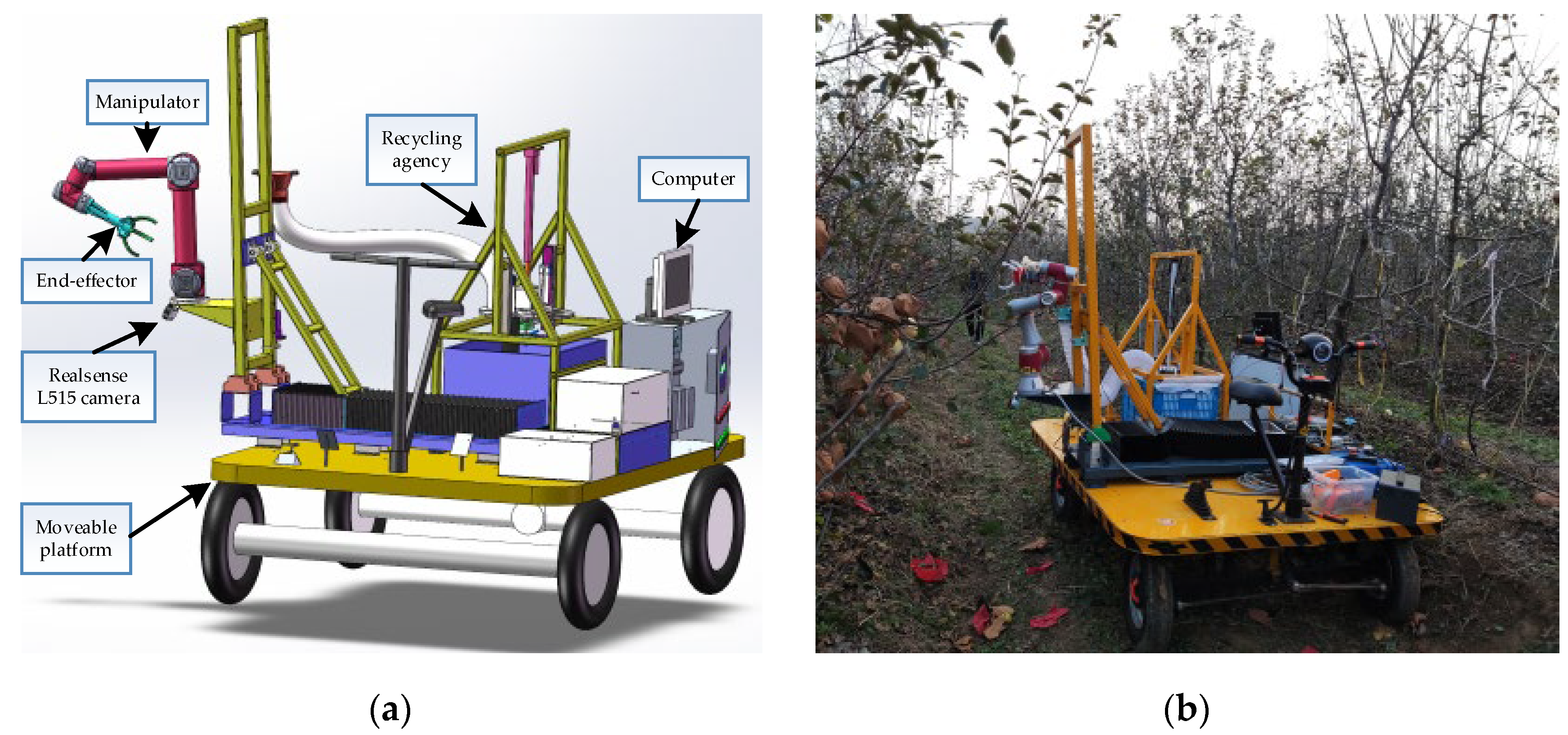
2.1. Components of the Apple-Picking Robot System

Considering the cost and the efficiency of picking, the apple-picking robot system designed in this paper adopts the eye-to-hand assembly method as Figure 1a. The RGB-D camera used is the Realsense L515 LIDAR camera from Intel, which has a good outdoor performance with an operating range of 0.25–9 m, depth map resolution of 1280 × 720, a frame rate of 30FPS, data transfer, and power supply by USB3.1, and it has a low power consumption of 3.5 W. The manipulator is a 6DOF collaborative manipulator developed by JAKA, with a payload of 3 kg, a self-weight of 12 kg, and a repeat positioning accuracy of ±0.02 mm. It has a drag and drop programming and a crash emergency stop function, making operation easier and safer. The end-effector is a 3D-printed three-finger gripper with a rubber layer inside the gripper that protects the fruit. The computer is configured with AMD R7-5800H CPU and 16 GB RAM. Other major components are a mobile platform, fruit recycling system, and outdoor lithium battery. Since the leaves on apple trees grow upward, and the fruit mostly grows naturally downward, observation from below can avoid the shading of most leaves on the fruit and branches, so the camera is mounted in an oblique upward position with the robot base, which can reduce the shading of leaves on the target and also increase the overlapping area between the visible space of the camera and the working area of the robot.
This system has been assembled as shown in Figure 1b, which shows an image of this apple-picking robot conducting a picking experiment inside an orchard. The following work has been performed in the current experiments: fruit recognition by the already mature YOLOv3 algorithm [20,21], with 96% recognition accuracy, which can meet the needs of the picking system. After that, the center of mass of the point cloud of the fruit area is found, and the center of mass is used as the position of the apple; then, the robot moves to the area to be picked first according to the preset point position and then moves to the position of the fruit for picking. Since the extracted fruit point clouds may contain point clouds on branches or leaves, the calculated apple positions may have deviations; moreover, the fruit growth characteristics are not considered when the robot is picking, and the planned picking paths are not adaptive, and there is a possibility of collision with branches in the picking process, as in Figure 2a,b. Therefore, it is necessary to improve the anti-interference ability and the adaptive ability of the path planning of the localization algorithm.

2.2. Calculation of Apple-Picking Direction

To prevent the end-effector from grasping the fruit and the branch at the same time, the end-effector needs to be as far as possible from the branches around the target fruit. As in Figure 2c, defining the picking direction of the apple to be in a direction that passes through the center of the apple and is perpendicular to the nearest branch of this apple can reduce the probability of the end-effector catching the branch [22].
The process of calculating the apple-picking direction defined in this paper is:
  • Firstly, the apple’s region of interest (ROI) is delineated in the RGB image using a target recognition algorithm.
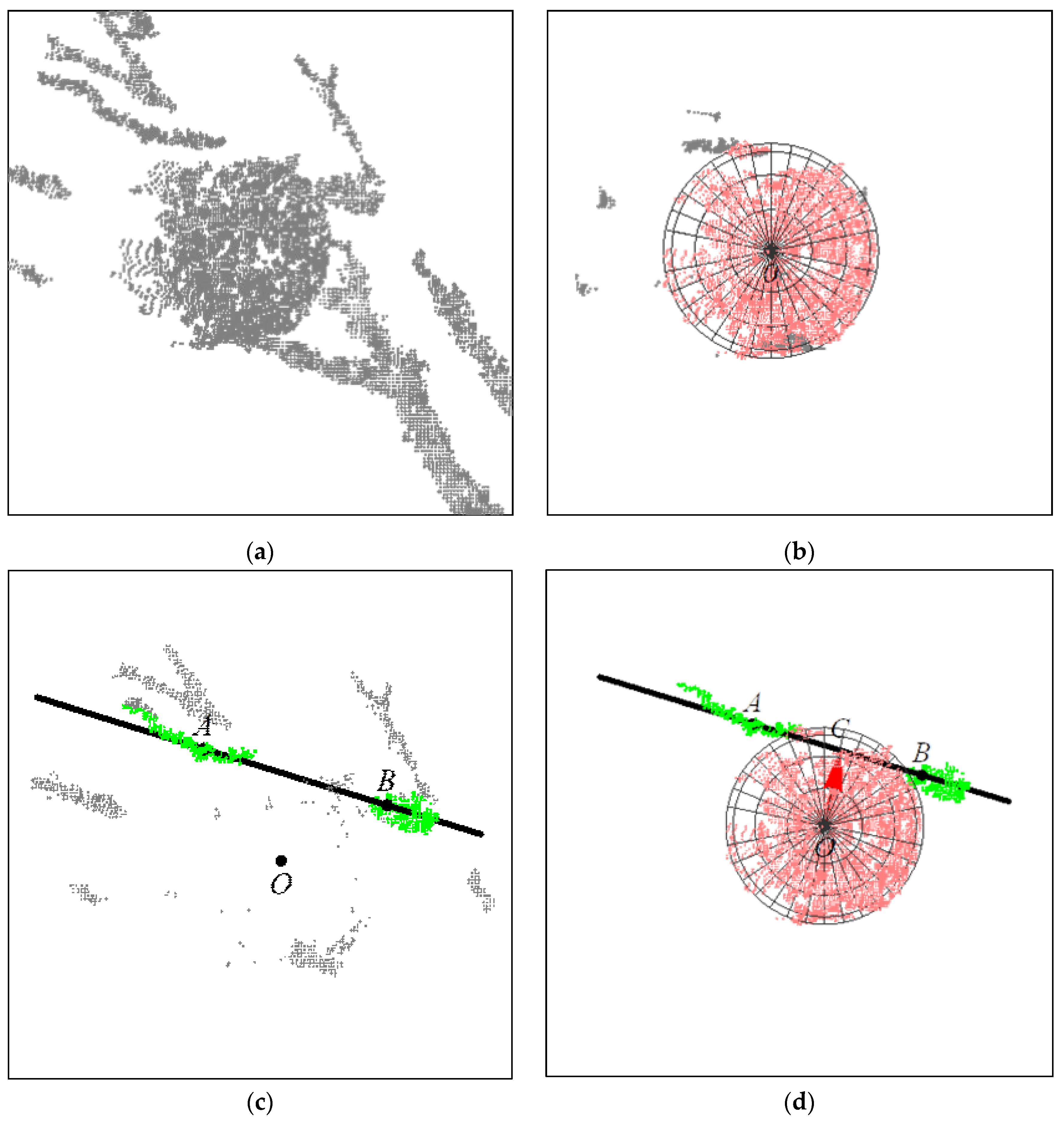
  • Secondly, segment the point cloud data inside this region, use the random sampling consistent algorithm (RANSAC) [23,24] to eliminate the abnormal data in the point cloud, and fit the point cloud of the fruit surface to a sphere, with the center of the sphere as the center of the apple, to improve the accuracy and anti-interference ability of the fruit localization algorithm.
  • Then, extract the point cloud of the sphere space with the target apple as the center and three times the radius of the fruit as the radius and use the RANSAC algorithm in this point cloud to extract the branch with the most surface point cloud that has the most influence on picking and fit it to a straight line.
  • Finally, the analytical geometry calculates the straight line over the center of the sphere and perpendicular to the known spatial line.
In Figure 3, the gray point cloud is the undefined point cloud, the pink point cloud is the apple surface point cloud, and the green point cloud is the branch surface point cloud. Point O is the center of the sphere fitted from the apple surface point cloud, and the black line is the line fitted from the branch surface point cloud. Points A and B are the two points on the branch line, and the red arrow is the picking direction OC. The apple centroid O and the picking direction OC are of great value for the planning of trajectories, but their detailed calculation process [22] is not overly described in this paper.

2.3. Obstacle Modeling

Since the apple trees are cluttered with branches and closely distributed fruits, the end-effector will collide with branches and other apples during the picking process, so both branches and other fruits have to be considered when planning the picking path. First, the branches and apples need to be transformed into spatial geometry with collision volume. Based on the morphological characteristics of the apples and branches, the apples are fitted as spheres, and the branches are fitted as parallel hexahedra.

2.3.1. Fitting the Fruit to a Sphere

The localization of the fruit mentions how to fit the point cloud of the fruit surface to a sphere by the RANSAC algorithm [22]. The spatial model of the apple can be established by using the center O and radius r of this sphere, and the space R s p h e r e occupied by the apple is:
R s p h e r e = x , y , z x x o 2 + y y o 2 + z z o 2 r 2
where x o , y o , and z o are the center points O x o , y o , z o of the sphere, and r is the radius of the sphere. If a point satisfies the above inequality, it means that this point is inside the fruit.
However, because the actual gripper has a certain size and is not an ideal point, if the trajectory planning is carried out directly using the center of the gripper, a collision will still occur. So, the actual size of the gripper must be considered, and to make the calculation easy, this part of the size is attached to the obstacle, and the gripper is considered an ideal point, but with a certain thickness of expansion outside the obstacle, and the thickness of expansion is determined by the length r g r i p from the center of the gripper to the edge of the gripper, so the collision model of the apple is as in Equation (2).
R a p p l e = x , y , z x x o 2 + y y o 2 + z z o 2 r + r g r i p 2
Thus, the coordinates of the end-effector will collide with the obstacle if it satisfies the above inequality; otherwise, no collision will occur.

2.3.2. Fitting Tree Branches to Parallel Hexahedra

In the process of picking apples, branches that are far away from the target fruit have less influence on the picking and are not considered here. The interference of the larger size branches around the target fruit to the end-effector is mainly considered. The point cloud M i n on the surface of branches distributed around the target fruit can be calculated in the previous section, and the spatial model of branches needs to be calculated here. In order to reduce the computational effort, the space occupied by branches is represented by an external parallel hexahedron that has the minimum volume. The parallel hexahedron R r e c t in space can be represented by the following equation:
R r e c t = O r e c t + a l v 1 + b w v 2 + c h v 3 a , b , c 0.5,0.5
where O r e c t is the center of the cube, l, w, and h are the length, width, and height of the cube, and v 1 , v 2 , and v 3 are the unit direction vectors in the three directions of the length, width, and height of the cube, and this space can be used to represent the space occupied by the tree branch. Similar to the apple model, considering that the end-effector has an actual size, this size needs to be added to the high aspect of the cube, and the collision model of the tree branch is shown in Equation (4):
R b r a n c h = O r e c t + a l v 1 + b w v 2 + c h v 3 a , b , c 0.5,0.5
where l = l + 2 r g r i p , w = w + 2 r g r i p , and h = h + 2 r g r i p . If a point in space satisfies the above equation, it means that the end-effector will collide with the tree branch at this point.
The procedure for calculating the minimum external parallel hexahedron of a point cloud is as follows:
  • Form the covariance matrix A with all the points in the electric cloud:
    A = c o v ( x , x ) c o v ( x , y ) c o v ( x , z ) c o v ( x , y ) c o v ( y , y ) c o v ( y , z ) c o v ( x , z ) c o v ( y , z ) c o v ( z , z )
    where:
    c o v X i , X j = E ( X i μ i ) ( X j μ j )
  • Solving the unit eigenvectors of the covariance matrix, which are the three principal directions v 1 , v 2 , and v 3 of the requested minimum external parallel hexahedron.
  • Rotate the three main directions obtained to be parallel to the axes of the world coordinate system, and the rotation matrix is R 3 = v 1 v 2 v 3 , and the point cloud after rotation is M i n :
    M i n = M i n · R 3
  • After rotating the point cloud in the main direction, the length, width, and height are calculated from the polar values of the three coordinates:
    l = x m a x x m i n w = y m a x y m i n h = z m a x z m i n
    where x m a x , y m a x z m a x , x m i n , y m i n , and z m i n are the maximum and minimum values of the rotated point cloud M i n in the direction of the x, y, and z three-coordinate axes.
  • Find the geometric center of the cube O r e c t ( x r , y r , z r )
    x r = ( x m a x + x m i n ) / 2 y r = ( y m a x + y m i n ) / 2 z r = ( z m a x + z m i n ) / 2
  • Since this center is obtained by rotating the point cloud, it is necessary to counter-rotate this center back to the original coordinate system:
    O r e c t = O r e c t · R 3 1
At this time, the center point O r e c t , length–width–height (l, w, h), and principal direction vectors ( v 1 , v 2 , v 3 ) of the minimum external parallel hexahedron of the branch point cloud have been found, and this parallel hexahedron is used to define the space occupied by the branch.

2.4. Picking Path Planning Based on Improved PSO Algorithm

In the above, information such as coordinates of the apple and surrounding obstacles have been obtained, after which it is necessary to find a path in space having the shortest length and avoiding obstacles. Currently, researchers have proposed a series of bio-inspired algorithms imitating natural phenomena of natural sciences [25], which are considered more suitable for path planning than the traditional artificial potential field method [26]. The PSO algorithm makes one of the four methods commonly used to solve robot path planning [27] but suffers from the problem of easily falling into local optima and needs to be optimized by changing the constraint parameters to fit to different scenarios [28]. To make the path smoother, polynomial equations are used to describe the picking path. To make this path with obstacle avoidance, a modified PSO algorithm proposed in this paper is used to adjust the path.

2.4.1. Mathematical Representation of Apple-Picking Paths

The method of polynomial interpolation is the most common method in trajectory interpolation [29], and its interpolated path is smoother, which can reduce the vibration during the movement of the manipulator.
In the continuous automatic picking process of the picking system, the end of the robot needs to reciprocate between the recovery point P 0 and the target fruit point O. The recovery point P 0 is a fixed value, and the recovery point is the starting point of the path in the process of going to pick the fruit, and to ensure that the robot will not collide with the recovery point, the end of the robot needs to be limited to leave the recovery pipe in the upward direction V 0 . The end-point of the path is the target fruit location O, and the direction of approaching the fruit is the apple-picking direction OC calculated above. To avoid collision with other fruits or branches during the picking process of the robot end-effector, it is necessary to set a transition point P m between P 0 and O to adjust the picking path.
From the five parameters, P 0 , V 0 , P m , O, and OC, a polynomial equation can be determined. Using this polynomial equation to represent the fruit-picking path, this polynomial function takes the following form:
F ( t ) = i = 0 4 A i t i t 0 , 1
where F t = x t , y t , z t denotes any point on the curve, and A i = a i , b i , c i denotes the vector of coefficients of each order in the equation. The five unknown vectors can be solved by the following five conditions, the conditions are:
F ( 0 ) = P 0 F ( 0 ) = V 0 F ( t m ) = P m F ( 1 ) = O F ( 1 ) = O C t m 0 , 1
The unknown coefficient vector can be solved by the above set of equations, where P m is the adjustment point of the path, and the selection of this point position determines the obstacle avoidance performance of the whole path, whose specific calculation process will be introduced in the next section. As the robot starts to reach into the canopy area for fruit picking in the second half of the path, it encounters more obstacles, so let t m = 0.75 in this paper, that is, let the point P m mainly adjust the second half of the path.

2.4.2. Obstacle Avoidance Point Selection Based on Adaptive Parameter PSO Algorithm

Finding a point P m in the robot workspace to make the shortest picking path length with obstacle avoidance capability is a complex task, and the speed of the search can be improved by the PSO algorithm. However, the standard PSO algorithm uses fixed weights, and it is difficult to find a suitable set of weights for a specific problem, so this paper proposes an adaptive weight PSO algorithm that can adjust the weights according to the historical fitness and the particle swarm center of mass. The flowchart of the PSO algorithm is shown in Figure 4.
The steps to find the optimal transition point P m in the picking path using the improved PSO algorithm are:
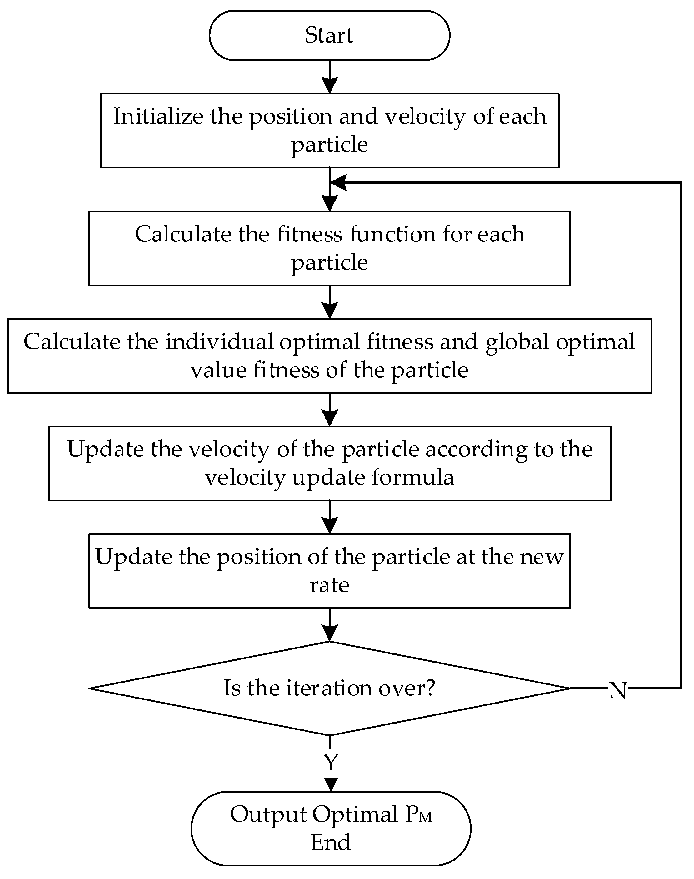
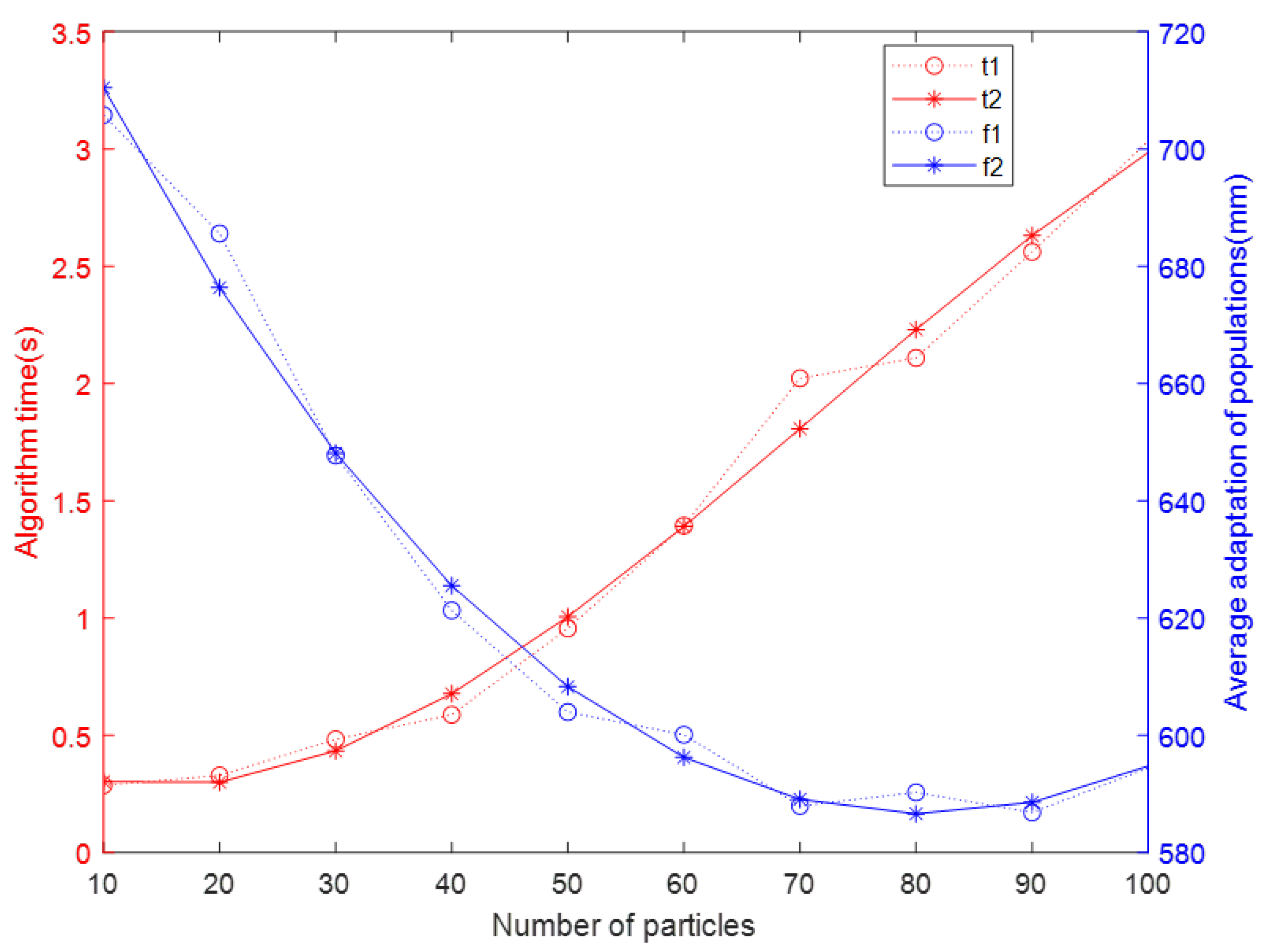
  • Initialization: In the robot workspace, n particles are randomly generated, and for each particle, an initial position P i , 0 and an initial moving velocity V i , 0 are randomly selected, and each particle can determine a picking path F i , j ( t ) , with i denoting the particle number and j denoting the number of iterations.
  • Calculate the fitness: Calculate the fitness of each particle at this time. In this project, use the length of the picking path as the fitness of this particle at this time, that is f i , j = 0 1 F i , j ( t ) d t , then the smaller the value of the fitness means that this particle is better. If this path collides with an obstacle, then this particle does not participate in the fitness evaluation this time and adjusts its moving direction so that the path avoids the obstacle.
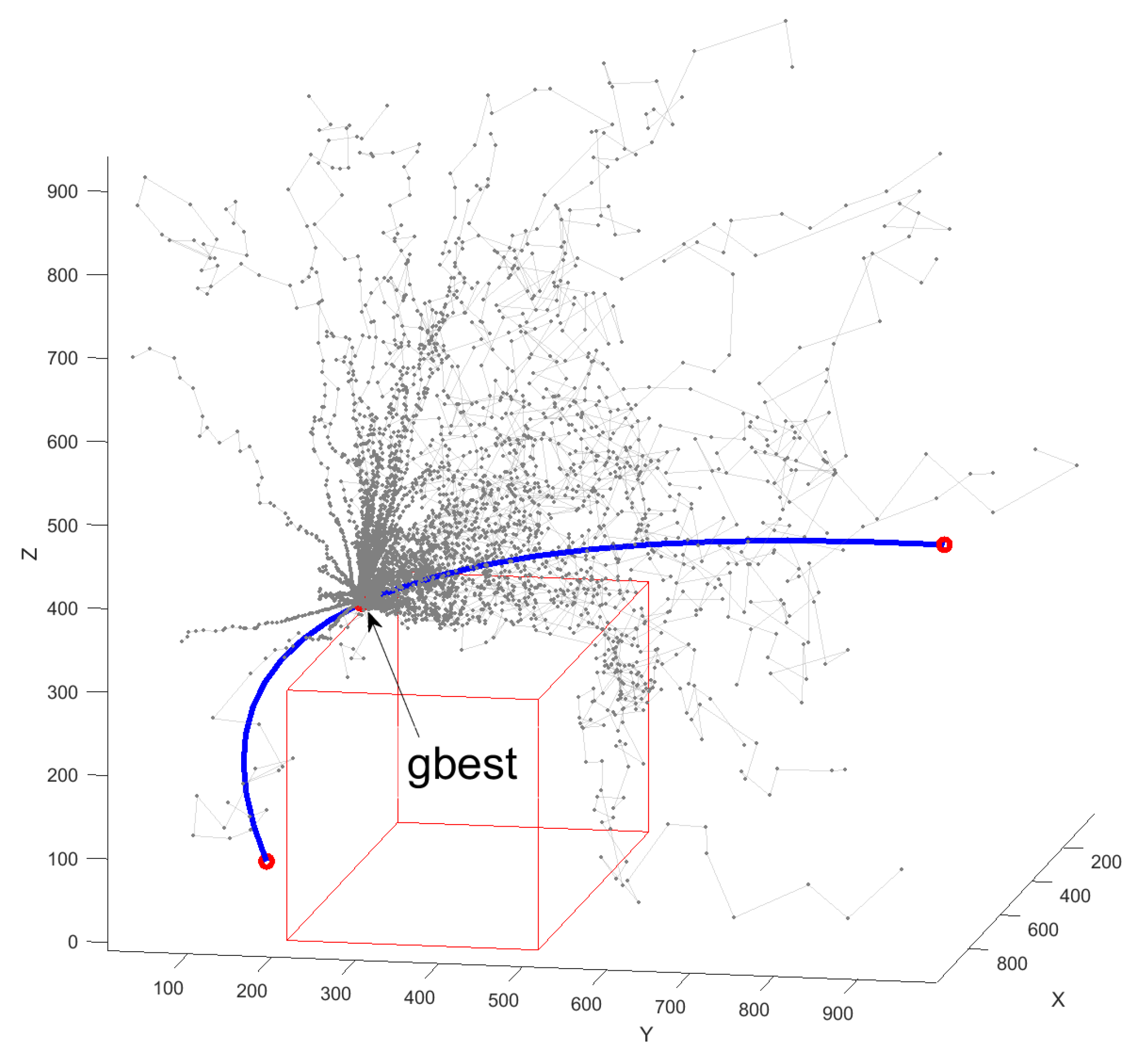
  • Find the individual history best adaptation value f i , j , p b e s t , that is, the best adaptation value in the first j iterations of the ith particle, whose corresponding particle position is P i , j , p b e s t .
  • Find the population’s best adaptation value f i , j , g b e s t , that is, the best adaptation value among all particles, and this particle position is P i , j , g b e s t .
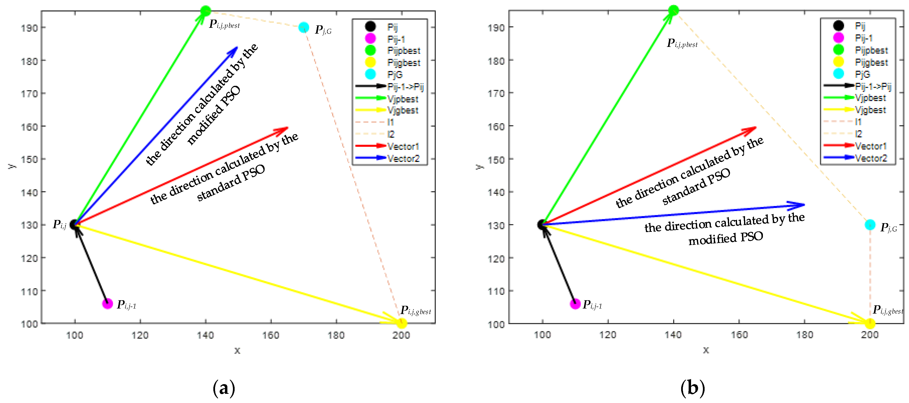
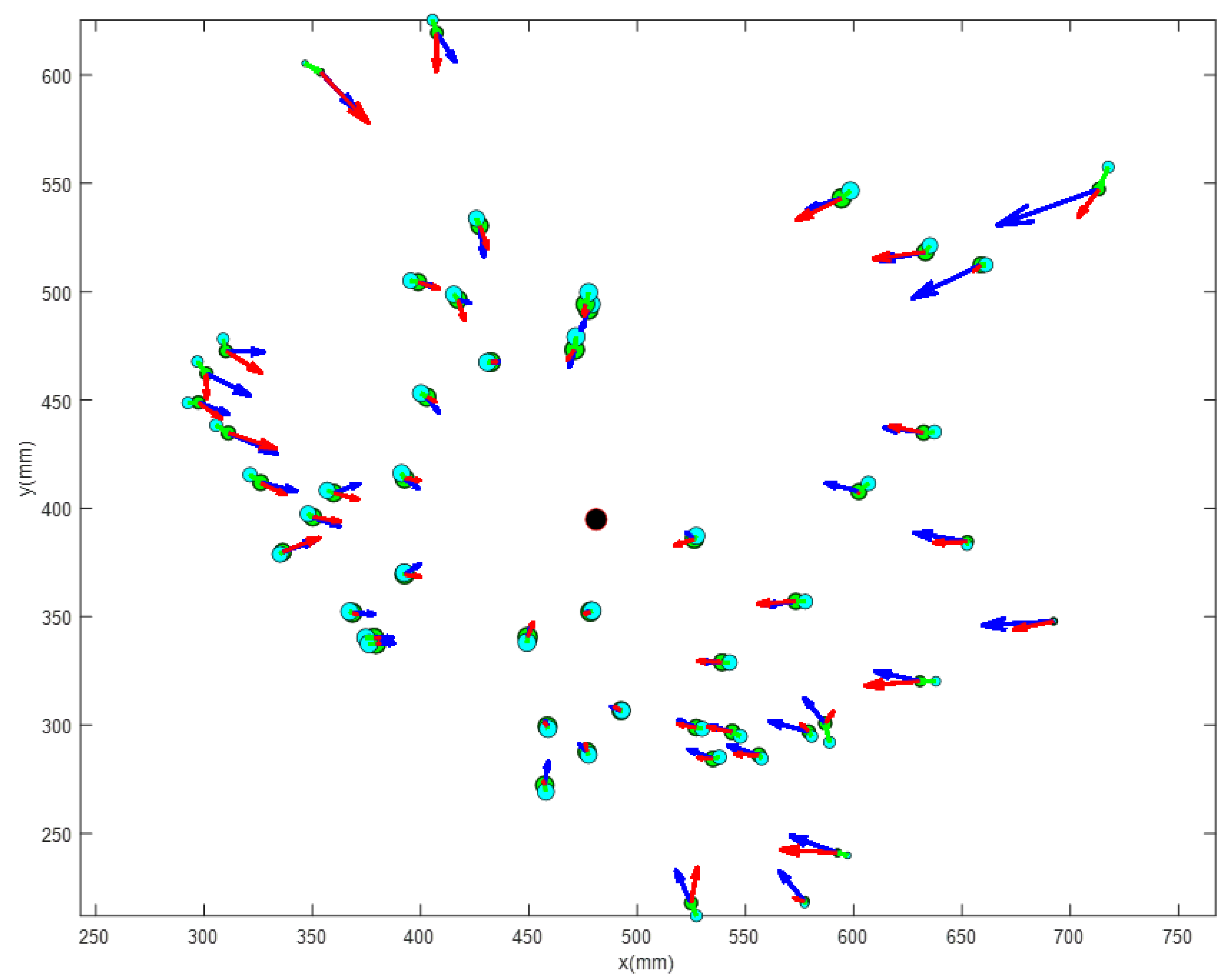
  • Update the velocity and position of the particles: The difference of the PSO algorithm with adaptive weights proposed in this paper is the way to update the velocity. Equation (13) is the particle velocity update formula.
    V i , j + 1 = w V i , j + c 1 r 1 P i , j , p b e s t P i , j + c 2 r 2 P i , j , g b e s t P i , j
    where r 1 and r 1 are random numbers between 0 and 1 to increase the randomness of particle search, w is the inertia weight, c 1 is the own learning factor, and c 2 is the population learning factor. To prevent the occurrence of a blind search of particles and skipping the optimal solution due to excessive velocity, the maximum value of velocity needs to be limited.
The particle positions are updated by:
P i , j + 1 = P i , j + V i , j + 1
In the standard PSO algorithm, w , c 1 , and c 2 are fixed values, which are difficult to find suitable parameters in practical applications and slow to converge. The weights of the PSO algorithm with adaptive weights proposed in this paper are calculated as follows:
w i , j = w 0 f i , j 1 / f i , j
c i , j , 1 = P i , j , g b e s t P j , G / P i , j , p b e s t P j , G + P i , j , g b e s t P j , G
c i , j , 2 = P i , j , p b e s t P j , G / P i , j , p b e s t P j , G + P i , j , g b e s t P j , G
The inertia weight w i , j is related to this particle’s current and last fitness values; if this fitness value is smaller than the last one, it means that the current velocity has a greater contribution (in this paper, the fitness value is the length of the path, so the smaller it is, the better the effect is indicated), so the higher the value of the inertia weight w i , j should be. The purpose of the coefficient w 0 is to allow the particle to gradually converge to the optimal point when the particle fitness hardly changes anymore, instead of jumping around the optimal point, and its value should be between 0 and 1. In this paper, we use w 0 = 0.5 . The center of mass of the particle population P j , G = 1 n i = 1 n P i , j is closer to the region of high particle density, and the region of high particle density generally has the optimal solutions that can guide the direction of particle movement. The adaptive learning factor used is when the particle individual best point P i , j , p b e s t is closer to the center of mass P j , G , shrink its own learning factor to prevent the occurrence of overshooting, and vice versa, increase its own learning factor to speed up its regulation. The same is true for the group learning factor. The difference between these two velocities can be illustrated by the following images:
The effect of the particle population center of mass position P j , G on the velocity direction is shown in Figure 5a,b. The center of mass position is closer to the individual optimal particle position in Figure 5a, and the center of mass position is closer to the population optimal particle position in Figure 5b. The red arrows in the figures show the calculated velocity vectors for the standard PSO with parameters w = 0.5 , c 1 = 0.5 , c 2 = 0.5 , r 1 = 1 , r 2 = 1 , which are not affected by the particle population center of mass position. The blue arrows are the vectors calculated by the algorithm of the modified PSO. The individual optimal particle position P i , j , p b e s t in Figure 5a is closer to the point P j , G than the population optimal particle position P i , j , g b e s t , so the velocity direction is more biased towards the point P i , j , p b e s t . In Figure 5b, point P i , j , g b e s t is closer to point P j , G , so the velocity direction is more biased towards point P i , j , g b e s t . By comparison, it can be seen that the blue vector is closer to the center of mass position of the particle population compared to the red one.
Figure 6 shows the comparison of the particle population using two different PSO algorithms to update the particle velocity after the 50th iteration. The light blue dot in the figure is the last position of the particle, the green dot is the current particle position, the red arrow is the velocity calculated by the standard PSO, the black dot is the current center of mass of the particle group, and the blue arrow is the velocity calculated by the modified PSO. A larger marker size indicates better adaptation of the point. From the figure, it can be seen that the particles closer to the center of mass have a better fitness, i.e., the shorter paths they constitute. The blue direction (calculated by the improved PSO) is closer to the center of mass of the population than the red direction (calculated by the standard PSO), so the blue direction allows the particles to move faster in the direction of higher fitness, which can improve the overall search speed.
Determine whether the convergence condition is satisfied: the convergence condition is that the distance between the particle population center of mass P j , G and the population best point P i , j , p b e s t is less than 1 mm, or the maximum number of iterations exceeds 1000. if the condition is not satisfied, return to Step 2; if the condition is satisfied, skip the iteration to output the best point P m .
The calculated P m is the transition point that can make the apple-picking path have the shortest length with obstacle avoidance capability.

3. Results

The previous section describes how to calculate the location of apples, the picking direction of apples, and how to use the improved PSO algorithm to find a point in space that can make the polynomial interpolation trajectory with the shortest length and obstacle avoidance capability. This chapter will experimentally verify the performance of the improved PSO algorithm and later verify how the algorithm performs in a real orchard scenario.

3.1. Experiment with Path Planning Based on Improved PSO Algorithm

Here, we mainly verify the performance difference between the improved PSO algorithm and the traditional PSO and whether the obstacle avoidance path calculated by the improved PSO algorithm is reasonable.
In the experiment, the starting position P 0 and velocity V 0 of the path are set first, and the end-point is set to the fixed position O and velocity OC; then, a parallel hexahedron is randomly generated between the two points as an obstacle in the space, and the maximum range of the trajectory is within a positive cube with a side length of 1000 mm. A modified PSO algorithm is used to find the best transition point P m in this space, and a polynomial trajectory is formed by P 0 , V 0 , P m , O, and OC.
The number of particles n is first determined according to the usage scenario.
From Figure 7, it can be seen that as the number of particles n increases, the time used by the improved PSO tends to increase, and the average fitness of the particle population tends to decrease (here, the fitness is the length of the path, so the smaller the value of the fitness, the better the effect). To balance the speed and accuracy of the algorithm, the number of particles is set to set the number of particles to 50, and in the experiment, the algorithm can end within 800 iterations, so the maximum number of iterations is set to 1000, and the results of the experiment are shown below.
In Figure 8, we can see that the particles gradually gather to the best point from the initial random distribution and move faster when they are far away from the best point, which can make the particles gather quickly and slow down when they are closer to achieve the purpose of the accurate search. The direction of the particle in the search process has a certain randomness, and it will adjust its velocity in the opposite direction to avoid the interference of obstacles when it collides with obstacles or search space boundaries. Finally, the particles gather on one edge of the parallel hexahedron, and the polynomial trajectory adjusted by this point crosses the surface of the obstacle without intersecting it, which means that this path has the function of obstacle avoidance, and the choice of this transition point is reasonable. This path is smooth, which can reduce the vibration when the manipulator is running.
After that, it was compared with the standard PSO algorithm, mainly comparing the number of iterations of the algorithm and the accuracy at convergence, and the comparison graph is shown in Figure 9:
The figure shows the average fitness of the particles in the iterative process of the two PSO algorithms. By comparison, we can see that the improved PSO algorithm starts with a slightly higher average fitness than the standard PSO when the particle distribution is more dispersed and the weight of the change velocity becomes larger so that the average fitness converges rapidly. After that, the particle distribution is more concentrated, and the weight becomes smaller accordingly for fine search. Therefore, it can be concluded that the PSO with adaptive weights converges faster and with higher accuracy than the standard-type PSO by the improved PSO.

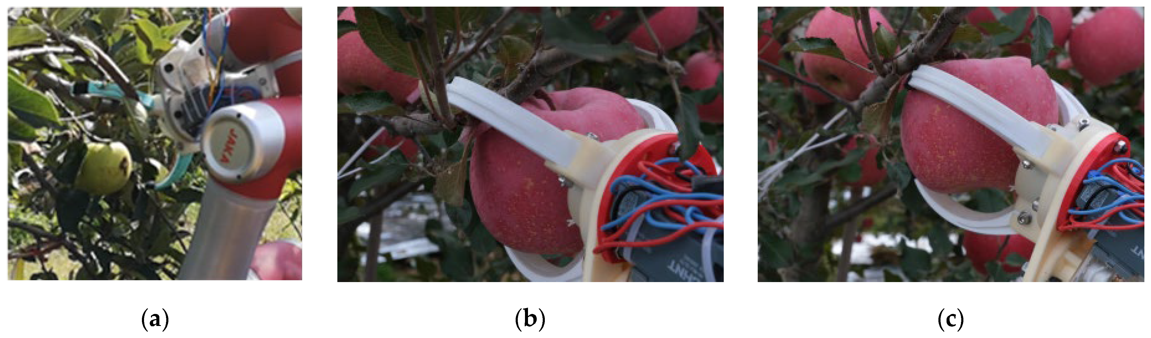
3.2. Experiments in an Orchard Environment

To further verify the effectiveness of the apple-picking path planning algorithm proposed in this paper, the original apple-picking robot is used as the experimental platform, and the apple pose estimation algorithm and trajectory planning algorithm of this paper are incorporated into the main controller in the form of C language. The images are obtained by RGB-D camera, and then the apple pose estimation algorithm is used to calculate the fruit-picking direction, followed by the trajectory planning algorithm to calculate the apple-picking path, and finally, it is discretized and input to the robot to perform the picking action. The images in the experiment are as follows:
Figure 10 shows the actual performance of the algorithm proposed in this paper in an orchard. Column 1 shows the recognition of apples by the YOLOv3 target recognition algorithm, and it can be seen that the algorithm can effectively recognize the fruit even if it is partially blocked by branches, leaves, or other fruits. Column 2 shows the point cloud of the fruit surface remaining after the segmentation of the point cloud inside the fruit recognition frame by RANSAC algorithm. It can be seen that some point clouds on the surface of branches and leaves that are obscured from the fruit have been successfully removed. Column 3 shows the point clouds on the surface of branches extracted by the RANSAC algorithm in the area around the fruit, and by comparing with the color image in Column 1, it can be seen that the thicker branches distributed around the fruit can be successfully recognized. Column 4 shows the fruit-picking direction calculated by the pose estimation algorithm and the robotic picking path generated by the transition points calculated by the PSO algorithm, and it can be seen that for each fruit, there is a different picking path, this path not only fits with the fruit pose, but also does not interfere with other fruits or branches and other obstacles, and has a certain obstacle avoidance capability.
In the orchard-picking experiments, two different methods were compared. In the first method, the fruit-picking attitude was not calculated, and there was no armband path planning. The position of the apple was determined using the mean value of the point cloud within the ROI, and the robot performed picking by pre-showing several points, varying only the target point. In the second experiment, the fruit surface point cloud was fitted to a sphere, and the center of mass of the sphere was used as the center of the fruit. Additionally, the fruit pose estimation algorithm and obstacle avoidance path planning algorithm were employed. The results of the experiments are presented in Table 2.
In the first experiment, the point cloud used for localization contained point clouds on the surface of branches and leaves, resulting in more noisy points due to the influence of sunlight, leading to deviations in localization. Additionally, since fruit-picking pose and obstacle avoidance were not considered, collisions between the gripper and branches often led to picking failure. In the second experiment, the RANSAC algorithm was used to fit the point cloud on the fruit surface to a sphere, which eliminated most of the noisy points and improved the stability of localization. Furthermore, using the proposed apple pose estimation method and path planning algorithm, 135 fruits were successfully picked with an 85.93% success rate. The path planning algorithm generated an exclusive shortest picking path for each fruit, resulting in an average picking cycle of about 12 seconds, which is more efficient than the traditional manual picking method that requires a group of two people and takes about 10 seconds to pick a fruit. The proposed picking method also has a higher success rate and efficiency compared to the traditional mechanical picking method. However, there were still some failed cases where fruits slipped out of the end-effector or multiple branches around the fruit caused collisions.

4. Discussion

The use of agricultural robots can result in cost savings and increased productivity, making it crucial to develop convenient automation equipment for unstructured agricultural environments. However, current apple-picking robots face challenges such as low efficiency and obstacle avoidance issues, highlighting the need to optimize the path planning method used by these robots.
To address these issues, this paper proposes a fruit-picking trajectory calculation method that uses polynomial interpolation to consider both the target position and the different growing positions of fruit on trees, resulting in a smooth and adaptive picking path that reduces robot vibration during movement. Experiments demonstrate that the improved particle swarm optimization (PSO) algorithm has a faster convergence speed than the standard PSO algorithm.
The paper also introduces an apple and branch extraction method that can effectively separate fruits and major branches from a point cloud map, with computational effort reduced by replacing apples and branches with simple geometric shapes. The improved PSO algorithm can then adjust the picking path by finding transition points with adaptive weights, resulting in a shorter path that avoids obstacles and increases the success rate of fruit picking.
Compared to traditional path planning methods, the improved PSO approach considers the growth attitude of each fruit and the branches distributed around it, leading to a reduced likelihood of fruit-picking failures due to collisions between robots and branches. The polynomial interpolation method provides a smooth path that reduces robot vibration and extends its service life.
Although this paper only calculated the branches closest to the fruit, there were still picking failures caused by collisions between the manipulator and branches. The presence of multiple large-diameter branches around some fruits significantly affects fruit picking, and the impact increases with branch density. Thus, future research should focus on extracting all branches around the fruit that may affect picking, constructing a spatial model of these branches, and planning the robot’s obstacle avoidance path in complex environments. At the same time, to adapt to a more complex environment, it is necessary to enable the PSO to find more transition points so that the path can bypass more obstacles.

5. Conclusions

For the problem that existing apple-picking robots are prone to collision with obstacles around the fruit during picking and cause picking failure, a method of planning the picking path of apple-picking robots using the PSO algorithm with adaptive weights is proposed. A polynomial interpolation function is used to represent this path, which requires first obtaining the location and picking direction of the target fruit, then finding a branch around the fruit that is closest to the fruit because it has the greatest impact on fruit picking; then, for computational convenience, the fruit and the branch are simplified to a sphere and a parallel hexahedron, and the other fruit and the surrounding branches are considered obstacles when the robot picks one fruit; finally, a PSO algorithm with weights that can be adaptively adjusted according to the population density is proposed, and this algorithm is used to find an optimal transition point in the manipulator workspace so that the polynomial path length is the shortest and does not collide with the obstacle. Through comparison experiments, it is verified that the improved PSO algorithm has better convergence speed, and the calculated adjustment points are applied to path planning, which can reduce the probability of collision between the apple-picking robot and obstacles in the process of approaching the fruit and improve the fruit-picking success rate; the generated path can be adaptively adjusted according to the specific location of the fruit and the surrounding environment, and it has a faster average picking speed than the fixed path. As this study only calculates one branch around the apple, the picking failure rate is higher when there are multiple branches with larger diameters around the fruit. Future research will focus on developing a method to calculate multiple branches around the fruit and increasing the number of transition points that the PSO algorithm searches for to enable the path to bypass more complex obstacles.

Author Contributions

Conceptualization, R.G. and Q.Z.; methodology, R.G., S.C. and Q.Z.; investigation, Q.Z.; data curation, R.G., S.C. and Q.J.; formal analysis, Q.Z. and Q.J.; writing—original draft, R.G.; writing—review and editing, S.C., Q.Z. and Q.J.; project administration, R.G.; funding acquisition, Q.J. All authors have read and agreed to the published version of the manuscript.

Funding

This research was supported by Industry-University Cooperation and Collaborative Education Project of the Ministry of Education (Grant Number: 221004992093933), and Zhejiang Province Lingyan Program (grant number: 2022C02052).

Data Availability Statement

The data presented in this study are available on request from the corresponding author.

Acknowledgments

The authors would like to thank the Key Laboratory of Transplantation Equipment and Technology of Zhejiang Province for their support. Special thanks to Shinehong Ma for providing the experimental equipment and experimental space. The assignments also thank Haiyao Xia, Zeqiang Sun and Chuang Li for their help in the experiments.

Conflicts of Interest

The authors declare no conflict of interest.

References

  1. Rose, D.C.; Wheeler, R.; Winter, M.; Lobley, M.; Chivers, C.A. Agriculture 4.0: Making it work for people, production, and the planet. Land Use Policy 2021, 100, 104933. [Google Scholar] [CrossRef]
  2. Duckett, T.; Pearson, S.; Blackmore, S.; Grieve, B.; Chen, W.H.; Cielniak, G.; Cleaversmith, J.; Dai, J.; Davis, S.; Fox, C.; et al. Agricultural robotics: The future of robotic agriculture. arXiv 2018, arXiv:1806.06762. [Google Scholar]
  3. Bechar, A.; Vigneault, C. Agricultural robots for field operations: Concepts and components. Biosyst. Eng. 2016, 149, 94–111. [Google Scholar] [CrossRef]
  4. Zhang, Z.; Heinemann, P.H.; Liu, J.; Baugher, T.A.; Schupp, J.R. The development of mechanical apple harvesting technology: A review. Trans. ASABE 2016, 59, 1165–1180. [Google Scholar] [CrossRef]
  5. Dong, G.; Zhu, Z.H. Position-based visual servo control of autonomous robotic manipulators. Acta Astronaut. 2015, 115, 291–302. [Google Scholar] [CrossRef]
  6. Arad, B.; Balendonck, J.; Barth, R.; Ben-Shahar, O.; Edan, Y.; Hellström, T.; Hemming, J.; Kurtser, P.; Ringdahl, O.; Tielen, T.; et al. Development of a sweet pepper harvesting robot. J. Field Robot. 2020, 37, 1027–1039. [Google Scholar] [CrossRef] [Green Version]
  7. Barth, R.; Hemming, J.; Van Henten, E.J. Angle estimation between plant parts for grasp optimisation in harvest robots. Biosyst. Eng. 2019, 183, 26–46. [Google Scholar] [CrossRef]
  8. Wang, X.; Kang, H.; Zhou, H.; Au, W.; Chen, C. Geometry-aware fruit grasping estimation for robotic harvesting in apple orchards. Comput. Electron. Agric. 2022, 193, 106716. [Google Scholar] [CrossRef]
  9. Kang, H.; Zhou, H.; Wang, X.; Chen, C. Real-time fruit recognition and grasping estimation for robotic apple harvesting. Sensors 2020, 20, 5670. [Google Scholar] [CrossRef]
  10. Kang, H.; Zhou, H.; Chen, C. Visual perception and modeling for autonomous apple harvesting. IEEE Access 2020, 8, 62151–62163. [Google Scholar] [CrossRef]
  11. Chen, W.; Xu, T.; Liu, J.; Wang, M.; Zhao, D. Picking robot visual servo control based on modified fuzzy Neural network sliding mode algorithms. Electronics 2019, 8, 605. [Google Scholar] [CrossRef] [Green Version]
  12. Ling, X.; Zhao, Y.; Gong, L.; Liu, C.; Wang, T. Dual-arm cooperation and implementing for robotic harvesting tomato using binocular vision. Robot. Auton. Syst. 2019, 114, 134–143. [Google Scholar] [CrossRef]
  13. Lin, G.; Tang, Y.; Zou, X.; Xiong, J.; Li, J. Guava detection and pose estimation using a low-cost RGB-D sensor in the field. Sensors 2019, 19, 428. [Google Scholar] [CrossRef] [Green Version]
  14. Vrochidou, E.; Tziridis, K.; Nikolaou, A.; Kalampokas, T.; Papakostas, G.; Pachidis, T.; Mamalis, S.; Koundouras, S.; Kaburlasos, V. An Autonomous Grape-Harvester Robot: Integrated System Architecture. Electronics 2021, 10, 1056. [Google Scholar] [CrossRef]
  15. Patel, R.V.; Shadpey, F.; Ranjbaran, F.; Angeles, J. A collision-avoidance scheme for redundant manipulators: Theory and experiments. J. Robot. Syst. 2005, 22, 737–757. [Google Scholar] [CrossRef]
  16. Zhang, H.; Zhu, Y.; Liu, X.; Xu, X. Analysis of obstacle avoidance strategy for dual-arm robot based on speed field with improved artificial potential field algorithm. Electronics 2021, 10, 1850. [Google Scholar] [CrossRef]
  17. Gul, F.; Mir, I.; Abualigah, L.; Sumari, P.; Forestiero, A. A consolidated review of path planning and optimization techniques: Technical perspectives and future directions. Electronics 2021, 10, 2250. [Google Scholar] [CrossRef]
  18. Zhou, C.; Huang, B.; Fränti, P. A survey of motion planning algorithms for intelligent robotics. arXiv 2021, arXiv:2102.02376. [Google Scholar]
  19. Contreras-Cruz, M.A.; Ayala-Ramirez, V.; Hernandez-Belmonte, U.H. Mobile robot path planning using artificial bee colony and evolutionary programming. Appl. Soft Comput. 2015, 30, 319–328. [Google Scholar] [CrossRef]
  20. Zhao, L.; Li, S. Object detection algorithm based on improved YOLOv3. Electronics 2020, 9, 537. [Google Scholar] [CrossRef] [Green Version]
  21. Kuznetsova, A.; Maleva, T.; Soloviev, V. Using YOLOv3 algorithm with pre- and post-processing for apple detection in fruit-harvesting Robot. Agronomy 2020, 10, 1016. [Google Scholar] [CrossRef]
  22. Gao, R.; Zhou, Q.; Cao, S.; Jiang, Q. An Algorithm for Calculating Apple Picking Direction Based on 3D Vision. Agriculture 2022, 12, 1170. [Google Scholar] [CrossRef]
  23. Nistér, D. Preemptive RANSAC for live structure and motion estimation. Mach. Vis. Appl. 2005, 16, 321–329. [Google Scholar] [CrossRef] [Green Version]
  24. Raguram, R.; Chum, O.; Pollefeys, M.; Matas, J.; Frahm, J.M. USAC: A universal framework for random sample consensus. IEEE Trans. Pattern Anal. Mach. Intell. 2012, 35, 2022–2038. [Google Scholar] [CrossRef]
  25. Yang, X.S. Nature-Inspired Metaheuristic Algorithms; Luniver Press: Beckington, UK, 2010. [Google Scholar]
  26. Wang, P.; Gao, S.; Li, L.; Sun, B.; Cheng, S. Obstacle avoidance path planning design for autonomous driving vehicles based on an improved artificial potential field algorithm. Energies 2019, 12, 2342. [Google Scholar] [CrossRef] [Green Version]
  27. Zhang, H.-Y.; Lin, W.-M.; Chen, A.-X. Path planning for the mobile robot: A review. Symmetry 2018, 10, 450. [Google Scholar] [CrossRef] [Green Version]
  28. Sengupta, S.; Basak, S.; Peters, R.A. Particle Swarm Optimization: A survey of historical and recent developments with hybridi-zation perspectives. Mach. Learn. Knowl. Extr. 2018, 1, 157–191. [Google Scholar] [CrossRef] [Green Version]
  29. Gasca, M.; Sauer, T. Polynomial interpolation in several variables. Adv. Comput. Math. 2000, 12, 377–410. [Google Scholar] [CrossRef]
Figure 1. Pictures of apple-picking robots: (a) system architecture of the apple-picking robot; (b) apple-picking robot picking in an orchard.
Electronics 12 01832 g001
Figure 2. Problems encountered by apple-picking robots during the gripping process: (a) end-effector stuck in a tree branch; (b) end-effector grabs both the apple and the branch; (c) end-effector grabs the apple perfectly.
Electronics 12 01832 g002
Figure 3. Pictures demonstrating the calculation process for apple-picking directions: (a) point cloud image of apple trees obtained by RGB-D camera; (b) fitting the fruit surface point cloud to a sphere; (c) fitting the point cloud on the surface of the nearest branch to the fruit to a straight line; (d) calculating the picking direction of the fruit based on the center of the fruit and the straight line of the branch.
Electronics 12 01832 g003
Figure 4. Flowchart of PSO algorithm.
Electronics 12 01832 g004
Figure 5. Diagrams of the PSO algorithm’s velocity update method: (a) the case where the best position of the particle history is closer to the center of mass of the particle population; (b) the case where the best particle of the population is closer to the center of mass of the particle group. Vector1 in the figure is the direction calculated by the standard PSO, and Vector2 is the direction calculated by the modified PSO.
Electronics 12 01832 g005
Figure 6. Comparison of the directions computed by the two algorithms during the iterative process.
Electronics 12 01832 g006
Figure 7. Algorithm time and final average adaptation values for different numbers of particles. In the figure, t1 is the sampling point of the algorithm time, and t2 is its least-squares fitting curve; f1 is the sampling point of the average adaptation of the particle swarm, and f2 is its least-squares fitting curve.
Electronics 12 01832 g007
Figure 8. The figure of the best excess point for particle swarm search. The red cube in the figure is the randomly generated obstacle cube, the red dots are the three interpolation points in the trajectory, the blue curve is the polynomial interpolation trajectory, and the gray trajectory is the particle swarm search trajectory.
Electronics 12 01832 g008
Figure 9. Comparison of the average adaptation of the improved PSO and the standard PSO during the iterative process.
Electronics 12 01832 g009
Figure 10. Experimental diagram of the apple-picking path planning algorithm. The first column shows the apples identified by the YOLOv3 algorithm, the second column shows the segmented apple surface point cloud, the third column shows the segmented branch surface point cloud, and the fourth column shows the calculated fruit-picking trajectory.
Electronics 12 01832 g010
Table 1. Comparison table of available fruit and vegetable picking robots.
Type of RobotEnvironmental Complexity LevelCostObstacle Avoidance CapabilityHarvesting Cycle
Automatic pepper-picking robot developed by Barth et al.SingleHighHigh15 s
Apple-picking robot with adjustable picking posture developed by Kang et al.ComplexHighModerate6.5 s
Apple-picking robot developed by Chen et al.ComplexModerateLow13.8 s
A two-arm collaborative tomato-picking robot developed by Zhao et al.ModerateHighModerate<30.0 s
Guava-picking robot developed by Lin et al.ModerateModerateHigh18.0 s
Grape-picking robot developed by Eleni et al.ModerateHighLowUnknown
Table 2. Experimental table comparing different path planning methods.
Experiment NumberPicking TimesNumber of SuccessesSuccess RateHarvesting Cycle
1875158.62%20 s
213511685.93%12 s
Disclaimer/Publisher’s Note: The statements, opinions and data contained in all publications are solely those of the individual author(s) and contributor(s) and not of MDPI and/or the editor(s). MDPI and/or the editor(s) disclaim responsibility for any injury to people or property resulting from any ideas, methods, instructions or products referred to in the content.

