Communication

Bistable Switch Based on Tunable Fano Resonance in Coupled Resonator-Cavity Structure

1
Jiangsu Key Laboratory of Micro and Nano Heat Fluid Flow Technology and Energy Application, School of Physical Science and Technology, Suzhou University of Science and Technology, Suzhou 215009, China
2
Science College, University of Shanghai for Science and Technology, Shanghai 200093, China
3
Department of Mechanical and Aerospace Engineering, University of Missouri, Columbia, MO 65211, USA
4
MOE Key Laboratory of Advanced Micro-Structured Materials, School of Physics Science and Engineering, Tongji University, Shanghai 200092, China
*
Authors to whom correspondence should be addressed.
These authors contributed equally to this work.
Electronics 2023, 12(9), 2023; https://doi.org/10.3390/electronics12092023
Submission received: 26 March 2023 / Revised: 19 April 2023 / Accepted: 26 April 2023 / Published: 27 April 2023
(This article belongs to the Section Optoelectronics)

Abstract

:
We report a side-coupled resonator-cavity configuration with a tunable Fano-type interference effect for a novel subwavelength switch. A defective microstrip photonic crystal (PC) structure is designed to provide a continuum state, while a split ring resonator (SRR) is introduced to offer a narrow discrete resonance. The SRR is conductively side-coupled with the microstrip PC cavity in a subwavelength volume. Interactions between them result in Fano-type transmitting spectra with a sharp and asymmetric spectral line profile. A varactor diode serving as the nonlinear medium inclusion is integrated into the slit of the SRR for active control of the sharp Fano resonance. The strongly localized field produced by Fano resonance plays a role in improving the nonlinear properties of the microstrip PC cavity. It is found that a significant blue shift of 94 MHz on the Fano resonance frequency can be achieved by increasing the input power levels from −25 dBm to 8 dBm. We also found that the maximum transmission contrast exceeding 15.9 dB can take place between two bistable states existing at 3.05 dBm and 4.32 dBm for a bidirectional sweep of input power under a monochromatic signal frequency of 1.27 GHz. The findings may benefit the exploitation of metamaterials-assisted active photonic nanocircuits.

1. Introduction

In recent years, the physics and designs of self-action devices have attracted tremendous research efforts for their potential to revolutionize photonics. A two-port bistable switch working as the “on–off” propagation part is a key component in integrated micro-circuits and on-chip interconnection systems [1,2,3,4,5]. A defective nonlinear photonic crystal (PC) in a one-dimensional region is of particular interest due to easy construction and convenient modulizations [6,7,8,9]. The defect mode of the PC has a stronger effect on electric field localization and its associated optical nonlinearity, which paves the way for one of the simplest two-port bistable switches. Much attention has been paid ever since the first theoretical prediction aimed at realizing a suitable candidate for low-cost integrated photonic circuits [10,11,12,13]. Normally, the transmission properties of the defect mode can be easily modified by appropriately altering the optical thickness of Bragg reflectors. It has been shown that the increased number of periods in Bragg reflectors enables a significant improvement in the Q-factor and light confinement effect of the defect mode, yielding an enhancement of nonlinear optical properties [14,15,16]. However, by doing this, the structure volume is bound to increase; meanwhile, the transmission coefficient will inevitably decline to a certain extent. These negative effects may eventually limit the practical application of PC-based switches, particularly in long-wavelength regions. Therefore, to miniaturize the defective PC for a high-performance bistable switching action, some auxiliary subwavelength designs relating to functional electromagnetic (EM) materials should be introduced.
Artificial micro-structured materials, such as metamaterials, have drawn much attention due to their unique ability to offer extraordinary phenomena that are not achievable in nature [17,18,19,20,21]. The periodical metallic resonant units are usually utilized to form metamaterials and hence provide diverse modulation approaches for manipulating light-matter interactions at the subwavelength scale. This characteristic makes them a promising candidate for future optoelectronic devices [21]. Recently, metamaterials have been designed to resemble the fascinating coherence effects occurring in multi-level atomic systems. In particular, Fano resonance in atomic and classical systems is becoming the focus of research [22,23,24,25,26]. Fano resonance in atomic systems originates from the quantum interference effect; namely, the discrete state destructively interferes with the continuum state, resulting in sharp and asymmetric transmitting spectra with steep dispersion. Fano resonance in classical systems is due to the coupling between a broad continuous spectrum and a narrow discrete spectrum, generating a typical Fano-type line shape. Till now, various artificial microstructures have been explored to mimic the Fano resonance phenomena, including hybrid graphene-metal gratings, whispering-gallery microresonators, side-coupled waveguide-cavity, gold nanoparticles, asymmetric SRR configurations, and dielectric clusters, covering from microwave to visible spectrum [27,28,29,30,31,32,33]. The Fano resonance phenomenon in metamaterials is always accompanied by a significant field enhancement at the subwavelength scale, which plays a pivotal role in the maximization of nonlinear interactions [34,35,36,37,38]. Moreover, it is noteworthy that the adjacent transmission peak–dip line shape possessed by Fano resonance can not only broaden the transmission contrast but also decrease the switching threshold, which is superior to Lorentz resonance. Therefore, Fano resonance in defective PC structures will be helpful for achieving miniaturized optical nanocircuits with excellent switching performance.
In this paper, we theoretically and experimentally demonstrate a side-coupled resonator-cavity configuration with a tunable Fano-type interference effect for a novel subwavelength switch. A defective microstrip photonic crystal (PC) structure (AB)3D(BA)3 is designed to function as a continuum energy state in a conventional Fano system. A split ring resonator (SRR) playing the role of a discrete excited state is etched in the middle region of the microstrip PC cavity. The SRR is conductively coupled with the PC cavity via a copper bar to increase the coupling strength. It is worth mentioning that if the SRR is placed away from the midpoint of the PC cavity, the coupling strength between them will more or less decrease. The destructive interference between the PC cavity and SRR resonance modes leads to a sharp and asymmetric Fano-type line shape. The localized field of the microstrip PC cavity is strongly enhanced by introducing the Fano-type scheme, which eventually generates a strengthened nonlinear response. The nonlinear medium inclusion, namely the varactor diode, is integrated into the slit of the SRR for active control of the Fano resonance. The tunable Fano-type line shapes can be obtained in the coupled resonator-cavity structure by dynamically changing the input intensity in the levels of −25 to 8 dBm. Consequently, a remarkable blue shift of 94 MHz on the Fano resonance frequency is observed within a subwavelength volume. We also found that the maximum transmission contrast exceeding 15.9 dB can take place between two bistable states existing at 3.05 dBm and 4.32 dBm for a bidirectional sweep of input power under a monochromatic signal frequency of 1.27 GHz. The findings may offer a platform for researching active classical analog to quantum phenomena in composite PC and metamaterial structures.

2. Model Design

The theoretical model of our Fano-based bistable switch is schematically illustrated in Figure 1a by using a nonlinear resonator side-coupled with a Fabry–Perot cavity in a two-port network system. The Fabry–Perot cavity can offer a continuum state; meanwhile, the resonator can supply a discrete state. The antisymmetric Fano-type line shape can be constructed analytically by involving destructive interference between the continuum state given by the Fabry–Perot cavity and the discrete state provided by the resonator. Then the nonlinear medium can be introduced into the resonator to provide a nonlinear response. When the antisymmetric mode is excited, together with the increased signal intensity, the confinement strength of the electric field in the nonlinear medium can be enhanced greatly, and hence the Fano-type spectrum blue shifts to the lower frequency region. In the vicinity of the Fano resonance peek and dip frequencies, the transmission on and off states can be obtained, as shown in Figure 1b. As the transmission-on state has a near-unity transparency window, whereas the transmission-off state possesses a near-zero transmission dip at the same frequency, the transmission contrast reaches its maximum. Hence, the high isolation between the Fano-type transmission on and off states of the proposed coupled resonator-cavity structure can lead to a high-performance bistable switching action.
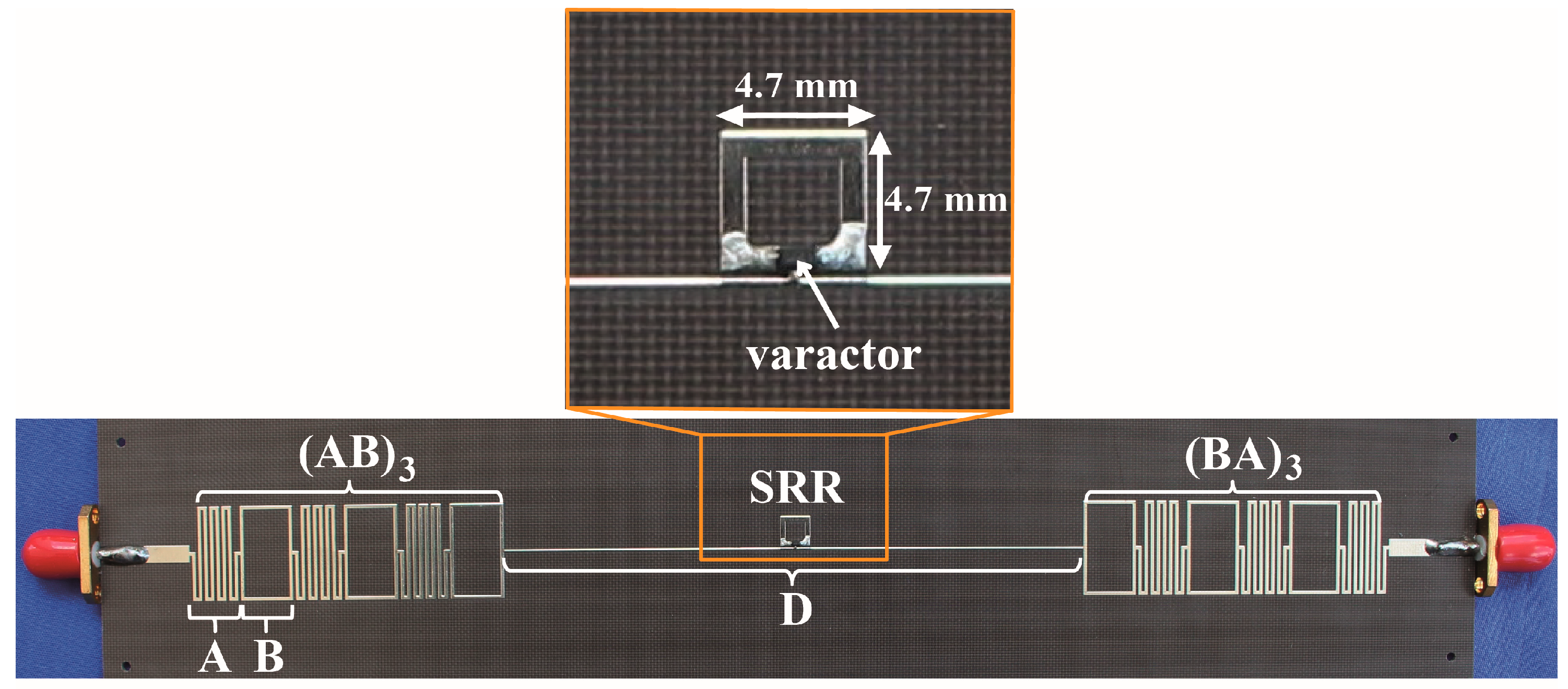
Microwave experiments are carried out to demonstrate the above physical concept by constructing the SRR side-coupled with a PC cavity as the Fano-based switch. Figure 2 displays the photograph of the fabricated coupled resonator-cavity sample. The metallic pattern is mounted on the top of the F4b substrate. The chosen substrate thickness is 1 mm, and the dielectric constant is 2.65. The thickness of the metallic pattern and the metal underlay is 0.035 mm. The total dimension of the sample is 224-mm-length × 44-mm-width. The top conductor microstrip line width is 2.7 mm, corresponding to the characteristic impedance of 50 Ω. The rectangular metal strips (flagged as B) and curved connecting strips (represented by A) are arranged periodically to form photonic bandgap (PBG) structures. The geometric parameters of a rectangular metal strip are 8.5 mm long, 15 mm wide, and 0.5 mm line width. The geometric parameters of the curved connecting strip are 8.5 mm long, 15 mm wide, 0.5 mm line width, and 0.5 mm gap width. The PCs (AB)3 and (BA)3, with periodic numbers equal to 3, function as two Bragg mirrors. The classical PC cavity structure is produced by introducing a defect (marked by D) between (AB)3 and (BA)3. The geometric parameters of the defect are 92 mm long and 0.5 mm wide. The SRR with a 0.8 mm line width and a 0.5 mm side gap is conductively coupled with the microstrip PC cavity via a copper bar to increase the coupling strength. The dimension of the copper bar is 0.3 × 0.3 mm2. The dimension of the square SRR is 4.7 × 4.7 mm2. An Infineon BBY52 varactor diode is used as nonlinear material and soldered at the gap of the SRR to tailor the Fano-type effect. Numerical simulations are performed by using CST software. Microwave experiments are carried out via a Keysight 85033E vector network analyzer, which supports a maximum power density of up to 15 dBm.

3. Simulations and Experiments

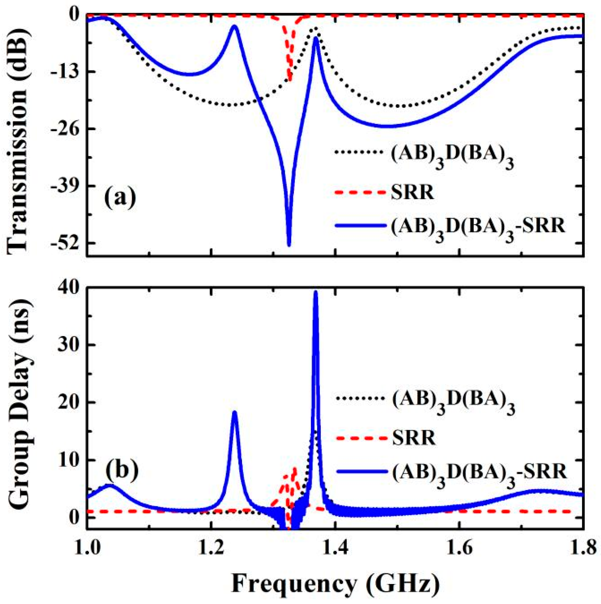
Firstly, the linear transmission spectrums of the PC cavity, SRR, and composite resonator-cavity structure are investigated by numerical simulations. In this case, we assign the capacitance of the varactor diode to 2.65 pF, according to the near-zero value of input power intensity. The black dotted line in Figure 3a illustrates that a typical Lorentzian line shape appears around 1.368 GHz when the EM signal is inputted into the individual PC cavity structure. The Q-factor of the Lorentzian line shape produced by the PC cavity is a mere 62.8, which can be well regarded as a continuum state. For individual SRR, the red dashed line shows that a narrow discrete mode emerges near 1.327 GHz with respect to the excitation of its magnetic dipole resonance. Through assembling the PC cavity with the SRR in the microwave waveguide system, the coherent interference between them occurred, resulting in a prominent asymmetric Fano-type spectrum. Note that the quality factor of the Fano-type transmission peak reaches up to 168.1, improved by order of magnitude compared to the individual PC cavity structure. For explicit comparison, the group delay of the above three structures is also calculated and depicted in Figure 3b. For individual PC cavity structures, the group delay is only 15.2 ns. For individual SRR structures, a deep negative group delay can be seen near its resonance frequency. However, for the composite resonator-cavity structure, the group delay is enlarged to 39.2 ns, demonstrating a significant slow-light effect. Therefore, the adjacent transmission peak–dip Fano resonance line shape possessed by coupled resonator-cavity configuration could be superior to the Lorentz resonance line shape owned by the PC cavity structure for the performance of the switching effect.
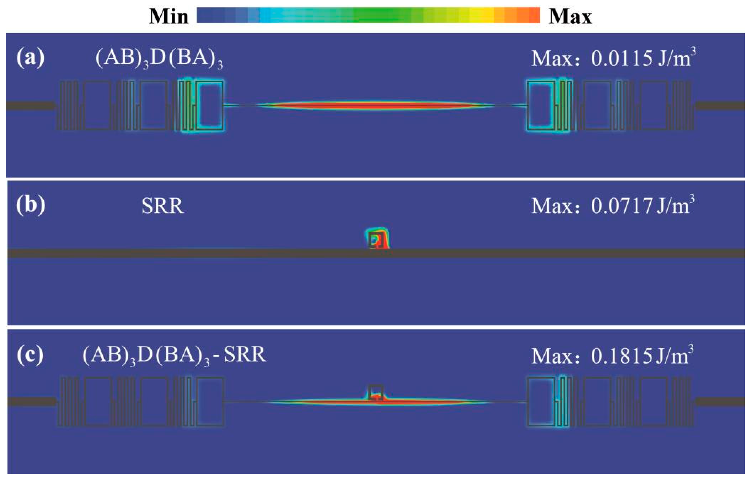
To dig deeper into the physical mechanism of Fano-type resonance, the normalized electrical energy density distributions of the PC cavity, SRR, and composite resonator-cavity structure are calculated and presented in Figure 4. The distributions of electrical energy density are normalized by their own maximum value. For the individual PC cavity structure at 1.368 GHz, it is clear that the EM fields locate in the shape of a standing wave pattern with a maximum electric energy density equal to 0.0115 J/m3. However, the two Bragg mirrors with limited periods beside the cavity do not have enough capability to strongly confine EM fields in the defect region. This weak confinement results in part of EM fields residing outside the defect. For the individual SRR structure at 1.327 GHz, we can see that EM fields are mostly localized along the ring with a maximum electric energy density equal to 0.0717 J/m3, indicating the excitation of magnetic resonance by the input EM waves. For the composite resonator-cavity structure at 1.368 GHz, the maximum electric energy density rises to 0.1815 J/m3, enlarged by one order of magnitude as compared to the above two individual structures. In addition, by using an electric field probe in CST software, the electric field density with 0.25 mm away from the midpoint of the PC cavity (4.6 × 10⁴ V/m), SRR (7.5 × 10⁴ V/m), and composite resonator-cavity (0.98 × 10⁵ V/m) is also obtained. That is the cooperation of the PC cavity and the SRR, enabling the EM fields confinement along two dimensions, namely, the longitudinal and lateral directions. The cooperation EM localization mechanism suggests the destructive interference effect, namely Fano resonance, in the coupled resonator-cavity structure. Moreover, it is significant that the enhanced EM field intensity in a Fano resonant structure can be utilized to essentially boost nonlinear response.
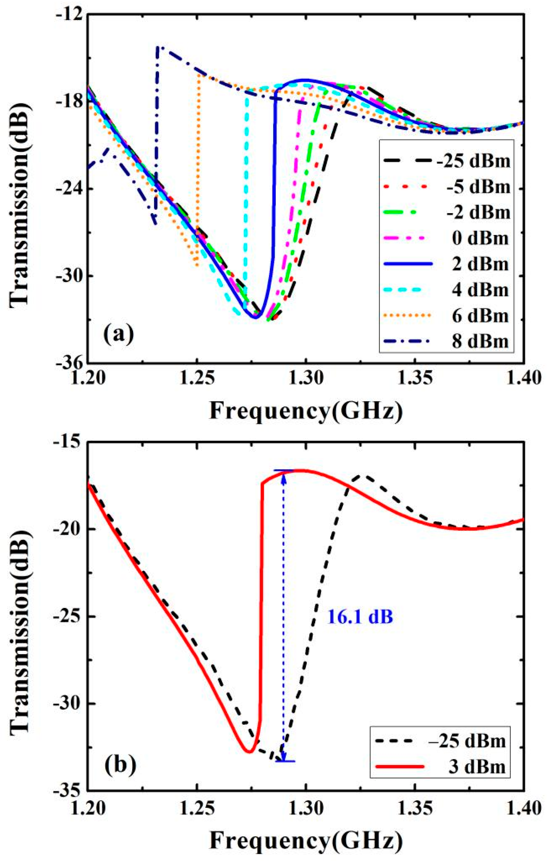
In what follows, transmission spectra of the coupled resonator-cavity structure are measured to characterize the switching action. The varactor diode is now loaded in the gap of the SRR for active control of the Fano resonance. Figure 5a presents the measured transmission (in dB) under different values of incident signal intensity (from −25 to 8 dBm). For low-input power situations, take −25 dBm for example, the Fano-type transmission peak obtained experimentally is located at 1.326 GHz. As an increasing intensity of input power, the notable nonlinear frequency shift in Fano-type transmission spectra is attached to the greatly enhanced local electric field in the varactor diode quantitatively; as the power intensity rises from −25 dBm to 8 dBm, the Fano-type transmission peek frequency blue shifts from 1.322 GHz to 1.228 GHz over 94 MHz. Meanwhile, remarkable nonlinear frequency shifts usually result in prominently modulating the transmission. As shown in Figure 5b, when comparing the transmission at 1.283 GHz under 3 dBm power intensity with that under −25 dBm power intensity, one can easily see a significant transmission contrast exceeding 16.1 dB. In this sense, the input-power-controlled coupled resonator-cavity structure in the microwave frequency band with tunable Fano-type effect and high transmission contrast can be implemented as an excellent two-port bistable EM switch.
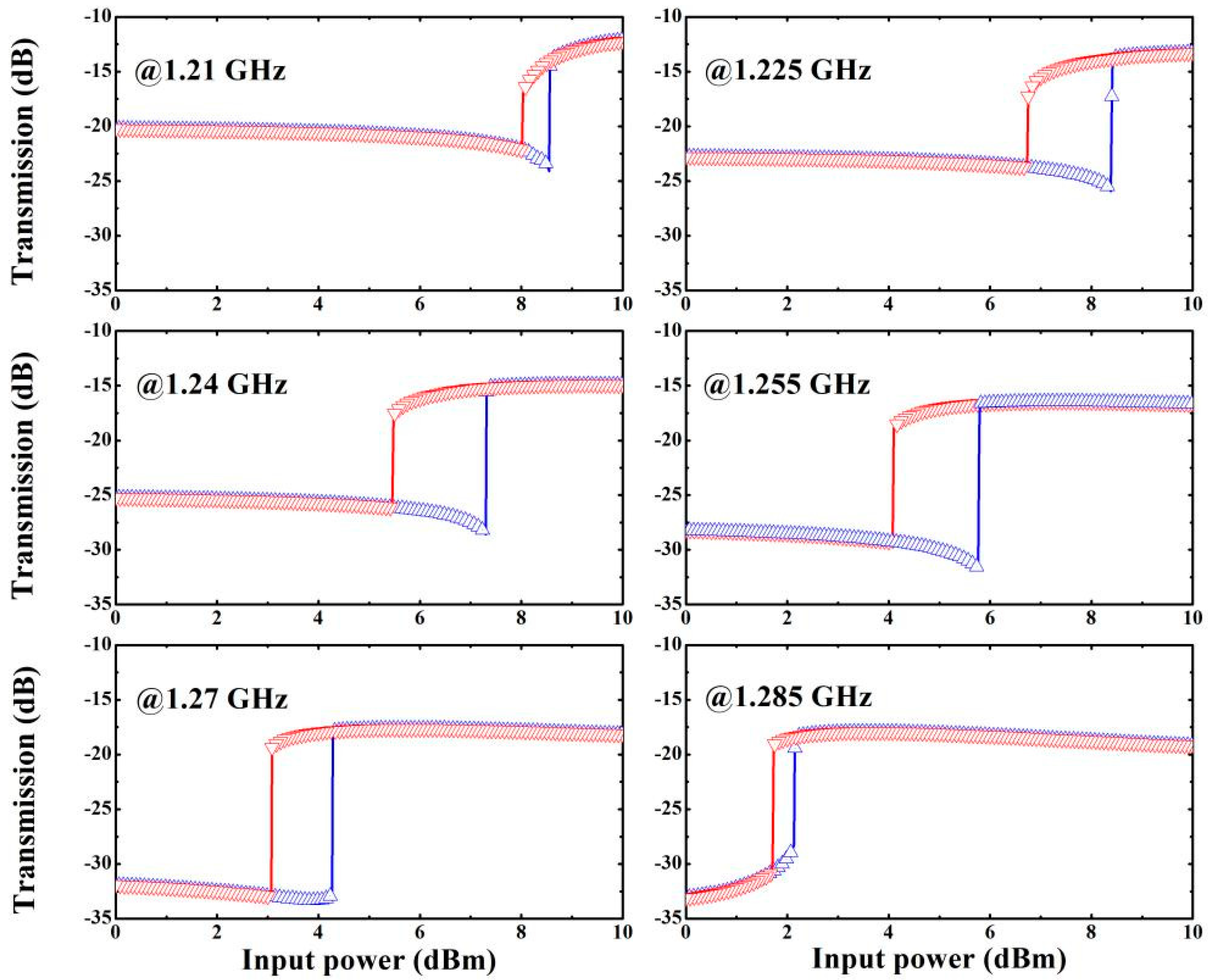
Finally, bistable transmissions versus bidirectional sweeping incident signal intensities in the coupled resonator-cavity structure are measured and presented in Figure 6. We introduce six monochromatic input EM waves at 1.21, 1.225, 1.24, 1.255, 1.27, and 1.285 GHz into the sample with incident intensities varied from 0 to 10 dBm. The blue triangles and red inverted triangles represent forward (increasing) and backward (decreasing) directions scan of incident intensities. Experimental results clearly show the frequency sensitivity of the hysteresis loop, including location, height, and width. As the frequency increases, there is a decrease in switch threshold power; meanwhile, there is an increase in transmission contrast. Taking 1.27 GHz as an example, two threshold levels exist at 3.05 dBm and 4.32 dBm. The different values of the transmission coefficient at one frequency are triggered by bidirectional scanning incident signal intensities in the region of the above two threshold levels. The difference between forward and backward transmission at 4.05 dBm is 15.9 dB, which is enough to meet the demands of general microwave components. Therefore, the proposed coupled resonator-cavity structure can work as a high-performance switch thanks to the adjacent transmission peak–dip line shape and the enhanced subwavelength EM field confinement of Fano-type resonance.

4. Conclusions

The study presented a compact Fano-type bistable switch using a coupled resonator-cavity structure. A quasi-one-dimensional microstrip PC with linear defect, namely (AB)3D(BA)3, is designed to function as a typical Fabry–Perot cavity. A split ring resonator (SRR) is embedded in the middle region of the microstrip PC cavity. The SRR is conductively coupled with the PC cavity via a copper bar to increase the coupling strength. The discrete SRR resonant mode destructive interferes with the continuum PC cavity mode resulting in the Fano resonance with a sharp asymmetric line shape. The nonlinear medium inclusion, namely the varactor diode, is integrated into the slit of the SRR for active control of the Fano resonance. A remarkable blue shift of 94 MHz on the Fano-type transmission spectra appears by raising the input power levels from −25 dBm to 8 dBm. Moreover, the maximum transmission contrast exceeding 15.9 dB takes place between two bistable states existing at 3.05 dBm and 4.32 dBm for a bidirectional sweep of input power under a monochromatic signal frequency of 1.27 GHz. With the development of new and rapidly micro-nano manufacturing processes, the proposed scheme may be extended to IR or optical regions and enrich the manifestation of a nonlinear bistable system.

Author Contributions

Conceptualization, Z.J. and L.G.; methodology, Y.F. and X.W.; software, L.G.; validation, Z.J.; formal analysis, Q.W.; investigation, Z.J. and L.G.; resources, Y.C.; data curation, L.G.; writing—original draft preparation, Z.J. and L.G.; writing—review and editing, Y.C. and Y.D.; visualization, Y.S.; supervision, Y.C. and Y.D.; project administration, Y.C.; funding acquisition, Y.C. All authors have read and agreed to the published version of the manuscript.

Funding

This research was funded by the National Natural Science Foundation of China (Grant No. 11974261), the Jiangsu Province Key Discipline of China’s 14th five-year plan (Grant No. 2021135), and the Jiangsu Students’ Innovation and Entrepreneurship Training Program (Grant No. 202210332020Z).

Data Availability Statement

The data used to support the findings of this study are available from the corresponding author upon request.

Acknowledgments

Many thanks to the editors and reviewers for their comments and help.

Conflicts of Interest

The authors declare no conflict of interest.

References

  1. Zharov, A.A.; Shadrivov, I.V.; Kivshar, Y.S. Nonlinear Properties of Left-Handed Metamaterials. Phys. Rev. Lett. 2003, 91, 037401. [Google Scholar] [CrossRef] [PubMed]
  2. Shadrivov, I.V.; Morrison, S.K.; Kivshar, Y.S. Tunable split-ring resonators for nonlinear negative-index metamaterials. Opt. Express 2006, 14, 9344–9349. [Google Scholar] [CrossRef] [PubMed]
  3. Powell, D.A.; Shadrivov, I.V.; Kivshar, Y.S. Nonlinear electric metamaterials. Appl. Phys. Lett. 2009, 95, 084102. [Google Scholar] [CrossRef]
  4. Wang, B.; Zhou, J.; Koschny, T.; Soukoulis, C.M. Nonlinear properties of split-ring resonators. Opt. Express 2008, 16, 16058–16063. [Google Scholar] [CrossRef] [PubMed]
  5. Huang, D.; Poutrina, E.; Smith, D.R. Analysis of the power dependent tuning of a varactor-loaded metamaterial at microwave frequencies. Appl. Phys. Lett. 2010, 96, 104104. [Google Scholar] [CrossRef]
  6. Mingaleev, S.F.; Kivshar, Y.S. Nonlinear transmission and light localization in photonic-crystal waveguides. J. Opt. Soc. Am. B 2002, 19, 2241–2249. [Google Scholar] [CrossRef]
  7. Soljačić, M.; Ibanescu, M.; Johnson, S.G.; Fink, Y.; Joannopoulos, J.D. Optimal bistable switching in nonlinear photonic crystals. Phys. Rev. E. 2002, 66, 055601. [Google Scholar] [CrossRef]
  8. Yanik, M.F.; Fan, S.; Soljačić, M. High-contrast all-optical bistable switching in photonic crystal microcavities. Appl. Phys. Lett. 2003, 83, 2739–2741. [Google Scholar] [CrossRef]
  9. Du, G.Q.; Jiang, H.T.; Wang, Z.S.; Chen, H. Optical nonlinearity enhancement in heterostructures with thick metallic film and truncated photonic crystals. Opt. Lett. 2009, 34, 578. [Google Scholar] [CrossRef]
  10. Tanabe, T.; Notomi, M.; Mitsugi, S.; Shinya, A.; Kuramochi, E. All-optical switches on a silicon chip realized using photonic crystal nanocavities. Appl. Phys. Lett. 2005, 87, 151112. [Google Scholar] [CrossRef]
  11. Hattori, T.; Tsurumachi, N.; Nakatsuka, H. Analysis of optical nonlinearity by defect states in one dimensional photonic crystals. J. Opt. Soc. Am. B 1997, 14, 348–355. [Google Scholar] [CrossRef]
  12. Ma, G.H.; Shen, J.; Rajiv, K.; Tang, S.H.; Zhang, Z.J.; Hua, Z.Y. Optimization of two-photon absorption enhancement in one-dimensional photonic crystals with defect states. Appl. Phys. B 2005, 80, 359–363. [Google Scholar] [CrossRef]
  13. Li, X.; Xie, K.; Jiang, H.M. Properties of defect modes in one-dimensional photonic crystals containing two nonlinear defects. Opt. Commun. 2009, 282, 4292–4295. [Google Scholar] [CrossRef]
  14. Aghaie, M.; Hebri, D.; Ghaedzadeh, A.; Bazyar, H. Controlled bistability by using array defect layers in one-dimensional nonlinear photonic crystals. Appl. Optics 2012, 51, 2477–2484. [Google Scholar] [CrossRef] [PubMed]
  15. Sharma, S.; Kumar, R.; Singh, K.S.; Kumar, V.; Kumar, A. Single channel tunable wavelength demultiplexer using nonlinear one dimensional defect mode photonic crystal. Optik 2015, 125, 4895–4897. [Google Scholar] [CrossRef]
  16. Cai, X.H.; Xu, Q.J.; Wang, S.W.; Li, S.H. Low-cross-talk and high-contrast all optical bistable switching based on coupled defects in a nonlinear photonic crystal cross-waveguide geometry. Photonic. Nanostruct. 2015, 13, 89–96. [Google Scholar] [CrossRef]
  17. Veselago, V. The electrodynamics of substances with simultaneously negative values of ε and μ. Sov. Phys. Usp. 1968, 10, 509–514. [Google Scholar] [CrossRef]
  18. Pendry, J.B. Negative Refraction Makes a Perfect Lens. Phys. Rev. Lett. 2000, 85, 3966–3969. [Google Scholar] [CrossRef]
  19. Shelby, R.A.; Smith, D.R.; Schultz, S. Experimental Verification of a Negative Index of Refraction. Science 2001, 292, 77–79. [Google Scholar] [CrossRef]
  20. Pendry, J.B.; Schurig, D.; Smith, D.R. Controlling Electromagnetic Fields. Science 2006, 312, 1780–1782. [Google Scholar] [CrossRef]
  21. Engheta, N. Circuits with Light at Nanoscales: Optical Nanocircuits Inspired by Metamaterials. Science 2007, 317, 1698–1702. [Google Scholar] [CrossRef] [PubMed]
  22. Fano, U. Effects of Configuration Interaction on Intensities and Phase Shifts. Phys. Rev. 1961, 124, 1866–1878. [Google Scholar] [CrossRef]
  23. Papasimakis, N.; Fedotov, V.A.; Zheludev, N.I.; Prosvirnin, S.L. Metamaterial Analog of Electromagnetically Induced Transparency. Phys. Rev. Lett. 2008, 101, 253903. [Google Scholar] [CrossRef]
  24. Zhang, S.; Genov, D.A.; Wang, Y.; Liu, M.; Zhang, X. Plasmon-Induced Transparency in Metamaterials. Phys. Rev. Lett. 2008, 101, 047401. [Google Scholar] [CrossRef] [PubMed]
  25. Liu, N.; Langguth, L.; Weiss, T.; Kästel, J.; Fleischhauer, M.; Pfau, T.; Giessen, H. Plasmonic analogue of electromagnetically induced transparency at the Drude damping limit. Nat. Mater. 2009, 8, 758–762. [Google Scholar] [CrossRef]
  26. Tassin, P.; Zhang, L.; Koschny, T.; Economou, E.N.; Soukoulis, C.M. Low-Loss Metamaterials Based on Classical Electromagnetically Induced Transparency. Phys. Rev. Lett. 2009, 102, 053901. [Google Scholar] [CrossRef] [PubMed]
  27. Fan, S.H. Sharp asymmetric line shapes in side-coupled waveguide-cavity systems. Appl. Phys. Lett. 2002, 80, 908–910. [Google Scholar] [CrossRef]
  28. Fedotov, V.A.; Rose, M.; Prosvirnin, S.L.; Papasimakis, N.; Zheludev, N.I. Sharp trapped-mode resonances in planar metamaterials with a broken structural symmetry. Phys. Rev. Lett. 2007, 99, 147401. [Google Scholar] [CrossRef]
  29. Guo, Z.W.; Jiang, H.T.; Li, Y.H.; Chen, H.; Agarwal, G.S. Enhancement of electromagnetically induced transparency in metamaterials using long range coupling mediated by a hyperbolic material. Opt. Express 2018, 26, 627–641. [Google Scholar] [CrossRef]
  30. Miroshnichenko, A.E.; Flach, S.; Kivshar, Y.S. Fano resonance in nanoscale structures. Rev. Mod. Phys. 2010, 82, 2257–2298. [Google Scholar] [CrossRef]
  31. Luk’yanchuk, B.; Zheludev, N.I.; Maier, S.A.; Halas, N.J.; Nordlander, P.; Giessen, H.; Chong, C.T. The Fano resonance in plasmonic nanostructures and metamaterials. Nat. Mater. 2010, 9, 707–715. [Google Scholar] [CrossRef] [PubMed]
  32. Singh, R.; Al-Naib, I.A.I.; Koch, M.; Zhang, W.L. Sharp Fano resonances in THz metamaterials. Opt. Express 2011, 19, 6312–6319. [Google Scholar] [CrossRef]
  33. Li, B.B.; Xiao, Y.F.; Zou, C.L.; Jiang, X.F.; Liu, Y.C.; Sun, F.W.; Li, Y.; Gong, Q.H. Experimental controlling of Fano resonance in indirectly coupled whispering-gallery microresonators. Appl. Phys. Lett. 2012, 100, 021108. [Google Scholar] [CrossRef]
  34. Xie, J.Y.; Hu, X.Y.; Wang, F.F.; Ao, Y.T.; Gao, W.; Yang, H.; Gong, Q.H. Ultralow-power on-chip all-optical Fano diode based on uncoupled nonlinear photonic-crystal nanocavities. J. Opt. 2018, 20, 034004. [Google Scholar] [CrossRef]
  35. Sun, Y.; Tong, Y.W.; Xue, C.H.; Ding, Y.Q.; Li, Y.H.; Jiang, H.T.; Chen, H. Electromagnetic diode based on nonlinear electromagnetically induced transparency in metamaterials. Appl. Phys. Lett. 2013, 103, 091904. [Google Scholar] [CrossRef]
  36. Chen, Y.Q.; Dong, L.J.; Fang, Y.; Wu, X.Z.; Wu, Q.Y.; Jiang, J.; Shi, Y.L. Bistable switching in electromagnetically induced-transparency-like meta-molecule. Appl. Phys. A Mater. 2019, 125, 22. [Google Scholar] [CrossRef]
  37. Chen, Y.Q.; Xu, G.Y.; Ding, Y.Q.; Fang, Y.; Wu, X.Z.; Wang, J.; Sun, Y. Electromagnetic diode action in an asymmetric side-coupled cavity-resonator system. Opt. Mater. Express 2021, 11, 3275–3283. [Google Scholar] [CrossRef]
  38. Fan, Y.C.; Qiao, T.; Zhang, F.; Fu, Q.; Dong, J.; Kong, B.; Li, H.Q. An electromagnetic modulator based on electrically controllable metamaterial analogue to electromagnetically induced transparency. Sci. Rep. 2017, 7, 40441. [Google Scholar] [CrossRef]
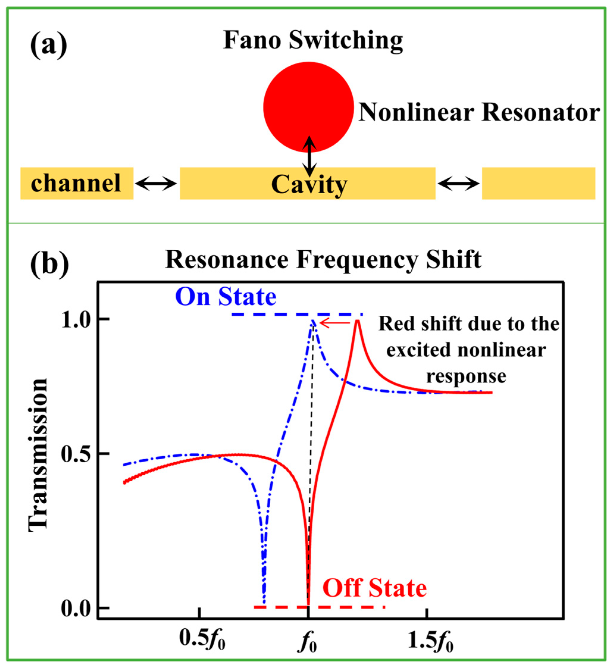
Figure 1. (a) Fano-based switching model. (b) Fano-type transmission on and off states.
Electronics 12 02023 g001
Figure 2. Photograph of the fabricated side-coupled resonator-cavity structure.
Electronics 12 02023 g002
Figure 3. Simulated (a) transmission spectra and (b) group delay for individual PC cavity, individual SRR, and composite resonator-cavity structure.
Electronics 12 02023 g003
Figure 4. Top view picture of normalized electrical energy density distributions in (a) PC cavity, (b) SRR, and (c) composite resonator-cavity structure. The distributions of electrical energy density are normalized by their own maximum value.
Electronics 12 02023 g004
Figure 5. (a) Measured transmission spectra for the coupled resonator-cavity structure with respect to input power. (b) Measured transmission spectra under two incident signal intensities of −25 dBm and 3 dBm.
Electronics 12 02023 g005
Figure 6. Measured transmission (in dB) at 1.21, 1.225, 1.24, 1.255, 1.27, and 1.285 GHz versus incident signal intensities varied from 0 to 10 dBm. The blue triangles represent the increase in incident EM wave intensity, while the red inverted triangles denote the decrease in incident EM wave intensity.
Electronics 12 02023 g006
Disclaimer/Publisher’s Note: The statements, opinions and data contained in all publications are solely those of the individual author(s) and contributor(s) and not of MDPI and/or the editor(s). MDPI and/or the editor(s) disclaim responsibility for any injury to people or property resulting from any ideas, methods, instructions or products referred to in the content.