Abstract
This study proposes an integrated framework of single-selection distributed antenna systems (DAS) and simultaneous wireless information and power transfer (SWIPT) with orthogonal multiple access (OMA), and analyzes the synergetic effects of SWIPT and DAS. To demonstrate the performance gains of the proposed SWIPT-enabled OMA with DAS, we jointly optimize power allocation for the OMA and power splitting (PS) ratio for energy harvesting of SWIPT with three different optimization goals: sum-rate maximization, user fairness, and energy efficiency. Although all of the above optimization problems are non-convex, the closed-form solutions of the problems maximizing the sum-rate and fairness are presented. Owing to difficult analytical tractability of the problem maximizing the energy efficiency, the problem is divided into three subproblems: power allocation for the base station (BS), power allocation for radio remote unit (RRU), and PS ratio assignment. Then, an iterative algorithm is presented to provide the energy-efficient SWIPT-enabled OMA with DAS. Theoretical findings are validated by numerical results, which show that the framework of applying DAS to SWIPT-OMA improves data rates and energy efficiency compared to SWIPT-OMA without DAS, while satisfying the minimum rate and harvested energy requirements.
1. Introduction
With the advent of high-bandwidth communication, both data traffic and energy consumption are rapidly increasing due to the development of Internet of Things (IoT) technology, in which numerous devices are connected and communicate [1]. To handle the above demands, multiple access technologies, wireless power transfer, and heterogeneous networks (HetNets) supporting IoT have been significantly investigated. In this paper, an integrated framework that provides high throughput, massive connectivity, and high energy efficiency is proposed.
1.1. Motivation and Related Work
Charging a large number of IoT devices with wires or replacing them physically is prohibitively expensive, and in certain cases, such as wireless medical instruments inside the human body, it is almost impossible [2]. To deal with this challenge, simultaneous wireless information and power transfer (SWIPT) that allows simultaneously transmitting information and power wirelessly has been extensively studied as a promising technology that can be applied to future IoT networks [3]. The SWIPT system employs two types of receivers: (1) power splitting (PS), which divides the received signal into two parts at an appropriate ratio in order to carry out information decoding (ID) and energy harvesting (EH) [4], and (2) time switching (TS), which uses two time slots for ID and EH [5], respectively. Furthermore, many studies have recently emerged that apply SWIPT to long-distance wireless communications.
However, because SWIPT requires larger received power for EH, it is very susceptible to channel gain degradation due to long-distance scenarios; thus, it is challenging to apply SWIPT to a wireless communication environment considering a relatively long distance. Furthermore, reduction of power transfer efficiency degrades the data rate for information transfer. To resolve this issue, wireless powered relay networks are presented to improve spectral and power efficiency [6,7]. Recently, applying SWIPT to non-orthogonal multiple access (NOMA) has been studied to boost the system throughput while serving multiple users [8]. For the SWIPT-NOMA system, the authors of [9] proposed power allocation methods to maximize the sum-rate and user fairness. In [10], the outage probability and throughput of SWIPT-enabled cooperative-NOMA in HetNet were analyzed, but without resource allocation, fixed power allocation and PS control were used. The authors of [11] proposed a user pairing scheme for maximizing spectral and energy efficiencies in the SWIPT-NOMA system. However, SWIPT-NOMA cannot fundamentally address the underlying issue of long distances. In this case, small nodes (e.g., access points) distributed within the coverage of a central processor (e.g., base station) can cooperate with the central processor to increase both the data rate and the energy efficiency of SWIPT.
Distributed antenna system (DAS) could be one solution to this distance-induced problem by supporting cell-edge users with weak channel gains from a base station (BS). In the DAS, multiple remote radio units (RRUs) are deployed within the BS coverage and provide sufficient data rates by cooperating with the BS [12]. RRUs are typically located near the edge of the BS coverage to support cell-edge users. The process of generating the cooperation signal and decoding the desired signal from the received signal at the RRU, which is the sum of signals transmitted from the BS and all RRUs, is similar to coordinated multipoint (CoMP). In the DAS, there are two transmission schemes: (1) blanket transmission and (2) single-selection transmission [13]. The blanket transmission allows the BS and all RRUs to send cooperation signals to a single cell-edge user, enabling the data rate of the user to be greatly increased while significantly interfering with other users. In the single-selection transmission scheme, the BS and only one RRU are able to send the cooperation signal to support the cell-edge user; therefore, the data rate is not as large as blanket transmission, but the interference power to other users is also lower. In general, for the single-selection transmission scheme, each RRU has its own coverage smaller than that of the BS, and the cell-edge user receives the cooperation signal from the RRU, whose coverage region includes the cell-edge user.
Even with the advantage of the DAS, there have not been enough studies on SWIPT in the DAS. Although the authors of [14] consider the DAS for SWIPT, their PS ratio assignment scheme does not aim for high energy efficiency. In [15], joint transceiver design for DAS-assisted full-duplex SWIPT systems under massive multiple-input multiple-output (MIMO) network was investigated. In addition, the authors of [16] proposed the resource allocation method for energy-efficient SWIPT in DAS, but they did not consider the user fairness because they did not distinguish between different types of users, i.e., cell-center and cell-edge users.
1.2. Contributions
This paper considers the single-selection DAS-assisted SWIPT-NOMA system with PS receiver. Joint optimal power allocation and PS ratio assignments methods are proposed to maximize the sum-rate, fairness, and energy efficiency when RRUs can support the cell-edge user, whose weak channel condition is because of the long distance from the BS. The proposed framework and optimization scheme can be easily extended to a general DAS as well as SWIPT-OMA.
The main contributions of this study are as follows:
- This paper proposes an architecture that incorporates DAS into the SWIPT-enabled OMA system and verifies the synergy effects of their integration. In the proposed framework, the RRU can boost the data rate and energy efficiency by assisting weak users with ID and EH.
- The optimization problems are formulated to maximize the sum-rate, fairness, and energy efficiency. We propose the joint optimal power allocation and PS ratio assignment methods while satisfying the minimum rate and harvested energy requirement. For the sum-rate and fairness maximization problems, we obtain the closed-form solutions. The energy efficiency maximization problem, on the other hand, is divided into subproblems, and solutions to the subproblems can be obtained by the bisection method. Following that, an iterative algorithm is used to find the jointly optimal solution.
- The numerical results revealed that applying DAS to SWIPT-enabled OMA resulted in a significant performance improvement when compared to other comparison techniques, and it was confirmed that the power was used more efficiently.
Note that our previous work [17] on SWIPT-OMA deals with optimal power and PS ratio assignments that maximize only energy efficiency as an objective function. Unlike our previous study, this paper includes the max-sum-rate and max-min-fairness problems, with optimal solutions presented. Therefore, this study is an extended version of the previous study.
The rest of the paper is structured as follows. Section 2 explains the system model. Section 3, Section 4 and Section 5 describe the joint optimal PS ratio assignment and power allocation schemes for maximizing the sum-rate, fairness, and energy efficiency, respectively. The numerical results are presented in Section 6, and the paper is concluded in Section 7.
2. System Model
2.1. Distributed Antenna System
This paper takes a look at a DAS-assisted multi-cell system, as shown in Figure 1, where each cell contains a BS and S RRUs. Figure 1 depicts a scenario with . RRUs are located near the cell edge and have their own coverage regions that are subsets of the entire cell region. BS can provide service to all devices in the coverage region, whereas RRUs can only support users in their own coverage regions. We assume that K cells in the vicinity of the target cell may interfere with the target cell. Here, the target cell index k is set to 0, and we define . Similarly, the index of the BS s is set to 0, and we have .
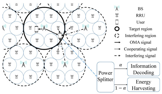
Figure 1.
Proposed DAS-applied SWIPT-OMA framework.
We look at two user scenarios: the cell-center user. who is only served by the BS, and the cell-edge user, who receives service not only from a BS but also from a nearby RRU. The goal of this research is to look into how power is allocated to these two types of users, as well as how to split power for ID and EH at these users. OMA is used to serve multiple users at the same time, and equal bandwidth is allocated to each user. Let and denote the BS and RRU transmit powers, respectively. Then, the total transmit power within the cell region is calculated as . The single-selection transmission scheme is used for the DAS in this study; in other words, only the RRU closest to the cell-edge user sends the cooperation signal. Herein, the cell-edge user is referred to as a user 1 or weak user, whereas the cell-center user is referred to as a user 2 or strong user.
2.2. Channel Model
In this study, we use the Rayleigh fading channel. The channel coefficient, , from the RRU i in region k to user j in the target region is expressed as , where and are slow and fast fading components, respectively, for , , and . is the path-loss exponent, and is the distance between user j of the target region and RRU i of cell k. For simplicity, we drop the index which indicates the target region, that is, . The BS uses the channel gain to determine user 1 (weak user) and user 2 (strong user) that satisfy .
2.3. DAS-Assisted Simultaneous Wireless Information and Power Transfer System
Let be the symbol sent from RRU i to user j for and . The received signals of user 1 and user 2 can be derived as:
for and . Here, and indicate the inter-cell interference and the noise at user j, respectively. The interference to user j from K interfering cells can be derived as:
where and represent the allocated powers of the BS in cell k, and represents the symbol sent from region k. Because the single-selection scheme is adopted, in the interfering cell k, only one RRU shares the frequency band with user 1 and user 2 of the target region, and the RRU’s index is denoted as in cell k. In addition, we suppose that and for all and .
Each user employs a PS receiver whose PS ratio is . Here, and of the received signal are used for ID and EH, respectively. Because the portion that is in phase with the received signal is not very large, we assume that the noise and interference cannot be harvested. Furthermore, according to [18], the power of the interference and noise are very difficult to be large enough to pass through the diode of rectifier.
The signal-to-interference-plus-noise ratio (SINR) of users 1 and 2 can be obtained by:
where is the variance of the inter-cell interference which can be obtained as:
Then, the data rates of users 1 and 2 are derived as:
where , , , and is the bandwidth. We assume that the half of the total bandwidth B is allocated to both users as in [19].
Even if the PS receiver decides to harvest power from the the received signal, it is impossible for the receiver to harvest without losses. The RF-to-DC power conversion function, according to: [20,21,22], can be modeled by a non-linear function as follows:
where is the input power of the RF-to-DC rectifier and is the maximum harvested power of the saturated EH circuit. In addition, a and b are constants determined by EH circuit properties, such as the resistance, capacitance, and diode turn-on voltage, as defined in [20,21,22]. Then, the energies harvested by user 1 and user 2 are represented as:
The important notations describing the system model are summarized in Table 1.

Table 1.
Summary of notations.
3. Optimal Sum-Rate Maximization Method
In this section, the optimal sum-rate maximization methods for SWIPT-OMA in DAS are presented. Let be the optimal power allocation of user 1, then is the optimal allocated power for user 2. Then, the sum-rate maximization problem can be derived as follows:
where is the sum-rate and is the minimum rate constraint. is the harvested energy requirement of user j. From now on, we propose an optimal closed-form solution of (14). According to (9) and (10), the inequality (14a) re-expressed and as follows:
where
The inequalities (14b) are also re-expressed as:
where is the solution of for , which can be obtained as:
To avoid an outage event, and should be satisfied. If not, the outage event occurs and . Now, for a given , the optimal PS ratios are obtained in Lemma 1.
Lemma 1.
For , if is positive, the optimal maximizing the sum-rate is obtained as .
Proof.
From now on, we find the joint optimal solution through Lemma 2 and Theorem 1.
Lemma 2.
Let and . For , is increasing for and decreasing for , where .
Proof.
Differentiating with respect to gives:
Thus, for and for . □
By substituting the obtained and into problem (14), the problem (14) becomes a single-variable problem for ; thus, the optimal allocated power can be found as in Theorem 1.
Theorem 1.
The optimal that solves the problem (14) can be obtained as:
where
when . If is satisfied, an outage event occurs.
Proof.
Let and be the solutions of and , respectively. Then, and can be obtained as (26) and (27), respectively. Because is decreasing for and is increasing for , the constraints (15) and (18) can be converted into . If , the feasible region of is empty, so an outage event occurs.
From Lemma 2, is increasing for and decreasing for . Thus, if , is a decreasing function of in the feasible region; therefore, . If , belongs to the feasible region of , so the optimal . Otherwise, if , is an increasing function of in the feasible region; therefore, . □
4. Optimal Fairness-Rate Maximization Method
In this section, we describe the optimal power allocation and PS control scheme for the max-min fairness problem. The optimization problem can be expressed as:
where . Because constraints (28a)–(28c) of the max-min fairness problem are same as constraints (14a)–(14c), the feasible region of becomes . The optimal PS ratios are obtained in the following lemma, which is similar to Section 3.
Lemma 3.
When , the optimal is derived as for .
Proof.
As shown in Lemma 1, since and are non-decreasing for both and , is also non-decreasing for both and . As a result, the optimal is the highest value in the feasible region. □
From now on, we find the joint optimal solution through Lemma 4 and Theorem 2.
Lemma 4.
For , is increasing for and decreasing for , where .
Proof.
By solving the inequality with respect to , we have . Thus, when , . Because is an increasing function for , is also increasing for . Otherwise, when , becomes . Because is decreasing for , is also decreasing for . □
Theorem 2.
The power allocation that solves the problem (28) can be obtained as:
when . If is satisfied, an outage event occurs.
Proof.
From Lemma 4, is increasing for and decreasing for . Thus, if , is a decreasing function of in the feasible region; therefore, . If , belongs to the feasible region of , so the optimal . Otherwise, if , is an increasing function of in the feasible region; therefore, . □
5. Energy-Efficient Power Allocation and Power Splitting Design
In this section, we jointly optimizes power allocation and PS for the cell-center user and the cell-edge user to maximize the energy efficiency of SWIPT-OMA in the DAS. In this paper, the energy efficiency is defined by the sum-rate over the total power consumption [2,16] as follows:
where is the overall power consumption, which is defined as . and are the consumed powers of the amplifiers in BS and RRU, respectively. is the power consumed by circuit parts, which includes the power used to run the digital signal processors, mixers, and so on. Then, the energy-efficiency maximization problem is formulated as follows:
where is the minimum rate constraint and and are the harvested power requirement for user 1 and user 2, respectively. Furthermore, and are the maximum power budgets of the BS and RRU, respectively. The energy efficiency is not convex with respect to , , , , and ; therefore, we propose an iterative algorithm for solving the problem of (31)–(31c).
5.1. Outage Event Condition
Before finding the optimal solution, we discuss the outage event of the problem (31) in this subsection. The first constraint (31a) of the problem (31) can be divided into and , which can be re-expressed with respect to as follows:
The minimum harvested energy constraints and can also be represented as follows:
In order for that satisfies (32)–(35) to exist, the following conditions should be satisfied:
where
Figure 2 shows a graphical representation of the feasible region of . The boundary of the feasible region consists of (36)–(39). If the region is an empty set, an outage event occurs. Therefore, we can state the following lemma.
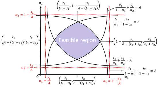
Figure 2.
Feasible region of .
Lemma 5.
If , an outage event occurs.
Proof.
From Figure 2, if or , the feasible region becomes empty and an outage event occurs. Those conditions are the same as . □
5.2. Optimal Power Allocation of Base Station
In this subsection, for a given , , and , we obtain the optimal power allocation for the BS, that is, and .
First, we propose the optimal for a given . According to (31a) and (31c), the feasible region of can be expressed as follows:
where and . Because the second-order derivative is negative, is a concave function for . We define , which can be derived as follows:
Because is negative, is a decreasing function for . Therefore, we can find the optimal for given the other optimization variables by applying the bisection method to .
The optimal for a given is derived in a similar way to obtaining the optimal . The constraint of can be expressed as follows:
where and . Here, the second-order derivative is also negative, so is a concave function for . With the definition , can be derived as follows:
The optimal can also be obtained by the bisection method.

5.3. Optimal Power Allocation of Remote Radio Units
In this subsection, we demonstrate the optimal power allocation of the RRU () for a given , , , and . The constraint of can be summarized as follows:
where . The second-order derivative of with respect to is also negative; therefore, is a decreasing function that can be derived as follows:
Similar to Algorithm 1, the optimal can be obtained by applying the bisection method to .
5.4. Optimal Power Splitting Ratio
In this subsection, strategies are introduced for obtaining the optimal and for a given , and . We sequentially obtain the optimal and . Then, an iterative algorithm is used to find the optimal .
For a given , the constraint of can be expressed as follows:
where and . With the definition , can be derived as follows:
Because is negative, is a decreasing function for .
For a given , the constraint of can be expressed as follows:
where and . Similar to before, can be obtained as follows:
where is also decreasing for ; therefore, the algorithm that finds the optimal follows the same process as in Algorithm 1.
5.5. Joint Power Allocation and PS Ratio Assignments
Now, we introduce the joint optimal solution for the original optimization problem (31). In our design, we obtain the optimal allocated powers and PS ratios successively, while assuming that the other variables are given, and apply an alternating algorithm to obtain the joint optimum solution. To summarize, the complete algorithm for maximizing the energy efficiency of the SWIPT-OMA in DAS is presented in Algorithm 2. The proposed scheme does not guarantee a global optimum owing to the non-convexity of (31), but finds a local maximum. Thus, random initial points are set.
| Algorithm 2: Joint optimal power allocation and power splitting ratio assignment |
for do  end Select , , , and which generate the maximum |
6. Numerical Results
This section provides numerical results to verify the DAS using SWIPT and OMA and the proposed jointly optimized power allocation and PS ratio assignments. For the simulations, interfering cells and RRUs in each cell are considered. The maximum transmit power budgets are assumed to be . The minimum rate constraints of the sum-rate and fairness-rate are assumed to be bps/Hz and bps/Hz, respectively, and the required harvested energies are set as mW. The pathloss exponent, cell radius, bandwidth, noise variance, and circuit power are set as , m, MHz, dBm/Hz, and W, respectively. In addition, we use mW, , and as in [21]. The cell-center user is generated uniformly within a circle with a radius of , whereas the cell-edge user is generated within outer and inner circle radii of R and , respectively.
For the sum-rate and the fairness-rate comparison, we compare the performance with SWIPT-OMA without DAS scheme named ‘SWIPT-OMA’. Note that the BS and the RRU always consume their full power, that is, and , respectively.
In Figure 3, the averaged optimal PS ratios for the max-sum-rate and the max-min-fairness problems are shown. As the power budget increases, the harvested energy requirement constraint can be satisfied by performing EH using only a small portion of the received signal; therefore, is also increased. As shown in Figure 3, has a smaller value than . Because channel environment of user 1 is weaker than user 2, user 1 utilizes a larger portion of the received power for EH than user 2. In addition, the values of ‘SWIPT-OMA-DAS’ is much larger than that of ‘SWIPT-OMA’, which implies that ’SWIPT-OMA’ has worse EH efficiency and requires more power for EH to satisfy the constraints.
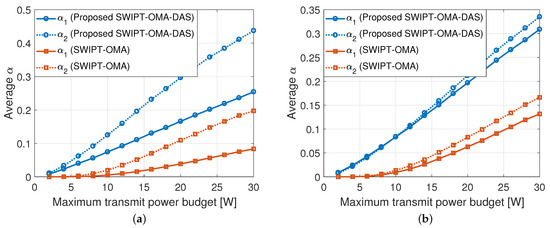
Figure 3.
Average power splitting (PS) ratios of max-sum-rate and max-min-fairness. (a) Average of the max-sum-rate problem. (b) Average of the max-min-fairness problem.
In Figure 4, the sum-rate and fairness-rate performances of the proposed technique and ‘SWIPT-OMA’ are compared. We assumed that the sum-rate and fairness-rate are zeros when the outage event occurs. As shown in Figure 4, the proposed schemes show much higher data rates than ‘SWIPT-OMA’. This is because DAS can overcome the data rate and EH degradation for a user who is far from the BS.
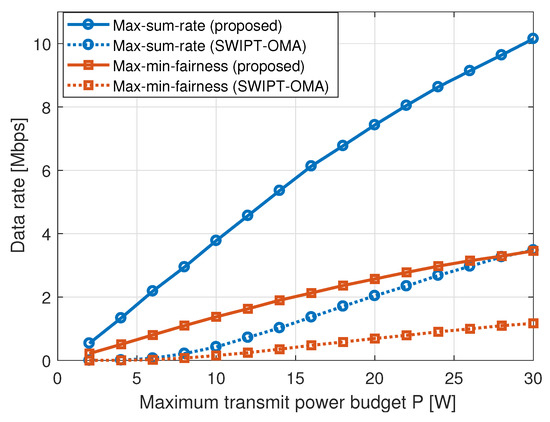
Figure 4.
Data rate performances with different power budgets.
To show the advantages of the proposed framework and the energy efficient joint power allocation and PS ratio assignments scheme, we compare the proposed technique with the following schemes:
- SWIPT-OMA: DAS is not employed; therefore, users receive data only through the BS. For , the optimal solution is obtained. The total power budget of the BS is supposed as for fair comparison.
- Rate-opt SWIPT-OMA in DAS: This scheme determines the power allocation and PS ratios to maximize the sum-rate rather than the energy efficiency, as in Section 3.
Figure 5 presents a comparison of the average PS ratio for different power budgets. In all the methods, the PS ratio of user 2, which has a relatively large channel gain, has a larger value than that of user 1. A large indicates that the PS receiver has decided to use a large portion of the received signal power for ID. Thus, ‘Rate-opt SWIPT-OMA in DAS’ selects a larger PS ratio than other schemes to boost the sum-rate without considering energy efficiency. The proposed scheme has a higher than ‘SWIPT-OMA’, because the user of the proposed scheme is more likely to receive a signal with higher power due to cooperation from a nearby RRU. Furthermore, we can see that the difference between users 1 and 2 is small in the proposed scheme, because the significant degradation of channel gain from the BS can be alleviated with the help of the RRU.
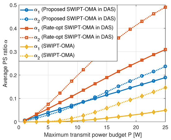
Figure 5.
Power Splitting (PS) ratios of various comparison schemes.
Figure 6 shows the multi-cluster impacts on data rates. For the multi-cluster scenario, we assume that the bandwidth and BS power budget are uniformly allocated to L clusters as and , respectively. If the number of clusters increases, the bandwidth and BS power allocated to each cluster decrease, making it difficult to guarantee the minimum data rate and minimum harvested energy requirements, after which more outage events occur; therefore, the performance decreases.
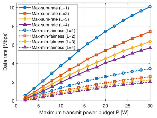
Figure 6.
Multi-cluster impacts on data rates.
Figure 7 and Figure 8 show the energy efficiency performance of the proposed and comparative methods with respect to the maximum power budget and minimum harvest power constraints, respectively. The energy efficiency increases as the maximum power budget grows, except for ‘Rate-opt SWIPT-OMA in DAS’, which does not pursue high energy efficiency. Similarly, as the minimum harvest power constraint increases, the energy efficiency of every comparison method decreases. We see that the proposed method is much more energy efficient than conventional schemes, and we see the significant benefit of using the DAS for SWIPT-OMA in both figures. As shown in Figure 5, ‘SWIPT-OMA’ has a smaller PS ratio , because it uses a larger portion of the received signal power to satisfy the minimum harvested energy constraint, so the proposed method shows better performance than ‘SWIPT-OMA’. Furthermore, with a limited power budget and/or a tight energy harvest constraint, the relative performance gain of the proposed scheme over other comparison methods grows.
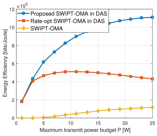
Figure 7.
Performance comparison of energy efficiency versus P for different schemes.
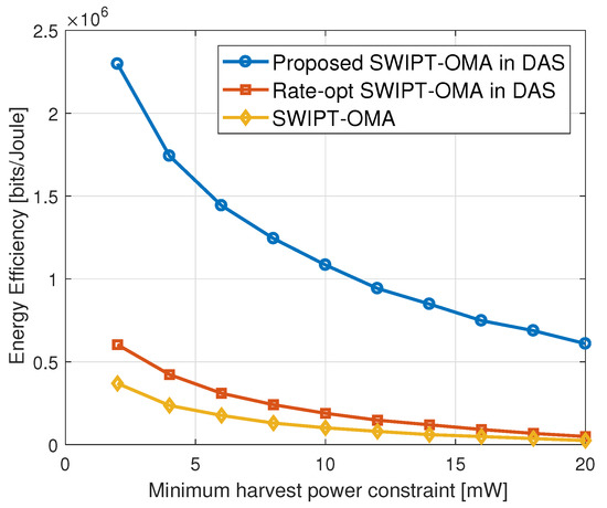
Figure 8.
Energy efficiency versus minimum harvested energy requirement.
7. Conclusions
This paper proposed a DAS-applied framework to improve the sum-rate, fairness-rate, and energy efficiency of SWIPT-OMA. Under the constraints of users’ minimum data rates and harvested energy requirements, we find the jointly optimal power allocation and PS ratios design schemes for both cell-center and cell-edge users in the proposed framework to maximize the sum-rate, fairness-rate, and energy efficiency, respectively. When a BS needs to provide service to a cell-edge user at a long distance from the BS, the DAS can send cooperative signals to improve data rate and energy efficiency performance. For the max-sum-rate and max-min-fairness problems, the optimal solutions were obtained in the closed-form expressions. To find the optimal solution that maximizes energy efficiency, we present an iterative algorithm that jointly derives the power allocation of BS for two different types of users and the PS ratios for energy harvesting for these users. The numerical results demonstrate the significant benefits of using DAS for SWIPT-OMA.
Author Contributions
Conceptualization, D.K., M.C. and D.-W.S.; methodology, D.K.; software, D.K.; validation, D.K., M.C. and D.-W.S.; formal analysis, D.K.; investigation, D.K., M.C. and D.-W.S.; resources, D.K.; data curation, D.K.; writing—original draft preparation, D.K., M.C. and D.-W.S. All authors have read and agreed to the published version of the manuscript.
Funding
This research was supported in part by the Basic Science Research Program through the National Research Foundation of Korea (NRF), funded by the Ministry of Education (No. 2021R1A6A3A01087324, No. 2022R1C1C1010766, No. 2022R1A4A3033401, No. 2021R1I1A3044405).
Data Availability Statement
The data were prepared and analyzed in this study and are available upon request to the corresponding author.
Conflicts of Interest
The authors declare no conflict of interest.
References
- Ku, M.L.; Li, W.; Chen, Y.; Liu, K.R. Advances in Energy Harvesting Communications: Past, Present, and Future Challenges. IEEE Commun. Surv. Tutor. 2016, 18, 1384–1412. [Google Scholar] [CrossRef]
- Kim, D.; Choi, M.; Seo, D.W. Energy-Efficient Power Control for Simultaneous Wireless Information and Power Transfer—Nonorthogonal Multiple Access in Distributed Antenna Systems. IEEE Trans. Ind. Inform. 2022, 1–12. [Google Scholar] [CrossRef]
- Krikidis, I.; Timotheou, S.; Nikolaou, S.; Zheng, G.; Ng, D.W.K.; Schober, R. Simultaneous wireless information and power transfer in modern communication system. IEEE Commun. Mag. 2014, 52, 104–110. [Google Scholar] [CrossRef]
- Zhou, X.; Zhang, R.; Ho, C.K. Wireless Information and Power Transfer: Architecture Design and Rate-Energy Tradeoff. IEEE Trans. Commun. 2013, 61, 4754–4767. [Google Scholar] [CrossRef]
- Lee, H.; Lee, K.-J.; Kim, H.; Lee, I. Joint Transceiver Optimization for MISO SWIPT Systems with Time Switching. IEEE Trans. Wirel. Commun. 2018, 17, 3298–3312. [Google Scholar] [CrossRef]
- Tang, X.; Cai, Y.; Wang, X.; Yang, W.; Song, Y.; Wang, L.; Yin, Z. Markov Chain Based Outage Analysis of Wireless Powered Relay Networks. In Proceedings of the 2019 IEEE 5th International Conference on Computer and Communications (ICCC), Chengdu, China, 6–9 December 2019; pp. 917–921. [Google Scholar]
- Singh, D.; Ouamri, M.A.; Alzaidi, M.S.; Alharbi, T.E.A.; Ghoneim, S.S.M. Performance Analysis of Wireless Power Transfer Enabled Dual Hop Relay System Under Generalised Fading Scenarios. IEEE Access 2022, 10, 114364–114373. [Google Scholar] [CrossRef]
- Xu, Y.; Shen, C.; Ding, Z.; Sun, X.; Yan, S.; Zhu, G.; Zhong, Z. Joint Beamforming and Power-Splitting Control in Downlink Cooperative SWIPT NOMA Systems. IEEE Trans. Signal Process. 2017, 65, 4874–4886. [Google Scholar] [CrossRef]
- Kim, D.; Choi, M.; Seo, D.-W. SWIPT-Enabled NOMA in Distributed Antenna System with Imperfect Channel State Information for Max-Sum-Rate and Max-Min Fairness. Available online: https://arxiv.org/pdf/2203.09769 (accessed on 18 March 2022).
- Parihar, A.S.; Swami, P.; Bhatia, V.; Ding, Z. Performance Analysis of SWIPT Enabled Cooperative-NOMA in Heterogeneous Networks Using Carrier Sensing. IEEE Trans. Veh. Technol. 2021, 70, 10646–10656. [Google Scholar] [CrossRef]
- Nguyen, T.-V.; Nguyen, V.-D.; da Costa, D.B.; An, B. Hybrid User Pairing for Spectral and Energy Efficiencies in Multiuser MISO-NOMA Networks with SWIPT. IEEE Trans. Commun. 2020, 68, 4874–4890. [Google Scholar] [CrossRef]
- Kim, D.; Choi, M. Non-Orthogonal Multiple Access in Distributed Antenna Systems for Max-Min Fairness and Max-Sum-Rate. IEEE Access 2021, 9, 69467–69480. [Google Scholar] [CrossRef]
- Choi, W.; Andrews, J.G. Downlink performance and capacity of distributed antenna systems in a multicell environment. IEEE Trans. Wirel. Commun. 2007, 6, 69–73. [Google Scholar] [CrossRef]
- Yuan, F.; Jin, S.; Wong, K.; Zhao, J.; Zhu, H. Wireless Information and Power Transfer Design for Energy Cooperation Distributed Antenna Systems. IEEE Access 2017, 5, 8094–8105. [Google Scholar] [CrossRef]
- Yang, H.; Xia, X.; Li, J.; Zhu, P.; You, X. Joint Transceiver Design for Network-Assisted Full-Duplex Systems with SWIPT. IEEE Syst. J. 2022, 16, 1206–1216. [Google Scholar] [CrossRef]
- Huang, Y.; Liu, Y.; Li, G.Y. Energy Efficiency of Distributed Antenna Systems with Wireless Power Transfer. IEEE J. Sel. Areas Commun. 2019, 37, 89–99. [Google Scholar] [CrossRef]
- Kim, D.; Choi, M.; Seo, D.-W. Distributed Antenna System-Assisted Energy Efficient SWIPT with Orthogonal Multiple Access. In Proceedings of the 2022 13th International Conference on Information and Communication Technology Convergence (ICTC), Jeju Island, Republic of Korea, 19–21 October 2022; pp. 1381–1386. [Google Scholar] [CrossRef]
- Boaventura, A.; Collado, A.; Carbalho, N.B.; Georgiadis, A. Optimum behavior: Wireless power transmission system design through behavioral models and efficient synthesis techniques. IEEE Microw. Mag. 2013, 14, 26–35. [Google Scholar] [CrossRef]
- Fu, Y.; Chen, Y.; Sung, C.W. Distributed Power Control for the Downlink of Multi-Cell NOMA Systems. IEEE Trans. Wirel. Commun. 2017, 16, 6207–6220. [Google Scholar] [CrossRef]
- Xu, Y.; Xie, H.; Liang, C.; Yu, F.R. Robust Secure Energy-Efficiency Optimization in SWIPT-Aided Heterogeneous Networks with a Nonlinear Energy-Harvesting Model. IEEE Internet Things J. 2021, 8, 14908–14919. [Google Scholar] [CrossRef]
- Jiang, R.; Xiong, K.; Fan, P.; Zhang, Y.; Zhong, Z. Optimal Design of SWIPT Systems with Multiple Heterogeneous Users Under Non-linear Energy Harvesting Model. IEEE Access 2017, 5, 11479–11489. [Google Scholar] [CrossRef]
- Xiong, K.; Wang, B.; Liu, K.J.R. Rate-Energy Region of SWIPT for MIMO Broadcasting under Nonlinear Energy Harvesting Model. IEEE Trans. Wirel. Commun. 2017, 16, 5147–5161. [Google Scholar] [CrossRef]
Disclaimer/Publisher’s Note: The statements, opinions and data contained in all publications are solely those of the individual author(s) and contributor(s) and not of MDPI and/or the editor(s). MDPI and/or the editor(s) disclaim responsibility for any injury to people or property resulting from any ideas, methods, instructions or products referred to in the content. |
© 2023 by the authors. Licensee MDPI, Basel, Switzerland. This article is an open access article distributed under the terms and conditions of the Creative Commons Attribution (CC BY) license (https://creativecommons.org/licenses/by/4.0/).