Article

Functional Damage Assessment Method for Preformed Fragment Warheads to Evaluate the Effect on the Phased-Array Antenna

1
College of Field Engineering, Army Engineering University of PLA, Nanjing 210007, China
2
Unit 32182 of PLA, Beijing 100042, China
3
Information Support Office, Army Logistics Department of PLA, Beijing 100072, China
*
Author to whom correspondence should be addressed.
Electronics 2023, 12(8), 1907; https://doi.org/10.3390/electronics12081907
Submission received: 19 March 2023 / Revised: 12 April 2023 / Accepted: 17 April 2023 / Published: 18 April 2023

Abstract

:
Damage assessment of a small-weight precision-guided warhead to evaluate the effect on the performance of high-value vulnerable targets should focus on functional damage instead of physical damage. Developing a damage assessment model that considers target function attenuation as a damage criterion for warhead design and tactical application is of great significance. In this paper, an accurate mathematical description of a preformed fragment warhead is provided. The failure of phased-array antenna elements in different initiation conditions is predicted by a shot-line model and spatial coordinate mapping. A real-time co-simulation model of the explosion damage field and the phased-array antenna electrical performance is developed and the effective damage modes are obtained through multi-condition simulation and electrical performance parameters analysis, which has more tactical application value than the structural damage assessment method with equivalent targets and the electrical simulation in artificial or random phrased-array-element failure conditions.

1. Introduction

The concept of the surgical strike was introduced by the US Air Force during the Cuban missile crisis in the 1960s. Subsequently, surgical strikes have been frequently used in modern wars, owing to their cost-effective performance and low risk of civilian casualties. Israel’s Babylonian operation is a classic example of the surgical strike application [1]. Gradually, the low-yield precision-guided warhead (LYPGW) has increased in importance in modern wars [2]. A preformed fragment LYPGW is a typical cylindrical charge warhead filled with fragments (e.g., metal balls or cylinders) surrounding the explosive as a casing. After detonation, the high-pressure fragments are transported at high velocities and are the primary source of damage. As the LYPGW is designed to impose accurate damage on high-value targets, the damage assessment of the targets should be based on functional attenuation rather than damage capability; this is in contrast to conventional warhead damage assessment methods.
Phased-array radar, the eye of the battlefield, is the priority target for precision attacks. The damage assessment of phased-array radar targets is an important research direction. As the exposed part of the phased-array radar, the antenna is the primary vulnerable target. Past studies have considered the antenna to be equivalent of the target plate and physical damage, such as deformation or perforation of the target plate as a criterion to analyze the penetration characteristics of a single fragment of the antenna-equivalent target plate [3,4,5]. The requirements for accurate, valuable, and real-time damage assessment results on the battlefield can be met by using theories of warhead damage field calculation. Fragments and shock waves are two typical destructive elements of a combat warhead. Since the lethality of the shockwaves decreases exponentially as the distance increases, and since it is difficult to quantitatively assess the damage caused by the shockwaves, our analysis of the damage of a low-yield preformed fragment warhead focused on the damage caused by fragments. Over the past 60 years, theoretical achievements of rapid calculation of the fragmentation field, including the fragment velocity and projection angle using semi-empirical formulas derived from energy analysis, have been constantly evolving [6,7,8,9,10,11,12,13,14]. The reliability of the latest empirical formulas has been verified by a numerical simulation and an experimental study [15]. The application of such empirical formulas in warhead damage assessment is considerably beneficial to the military field.
To further study the effect of fragment damage on the electrical performance of the antenna, the radiation pattern of a phased-array antenna was analyzed by setting different failure conditions for the array elements. Zhu et al. [16] analyzed the variation in electrical performance parameters of the Chebyshev linear array and the Taylor linear array when single and double array elements failed, respectively. Zhang et al. [17] analyzed the influence of single element failure at different positions on electrical performance parameters in a planar phased array. Xiong et al. [18] and Liu et al. [19] analyzed the variation of electrical properties of the planar phased-array antenna when different percentages of elements randomly failed. Furthermore, Keizer [20], Poli et al. [21], Muralidharan et al. [22], and Patidar et al. [23] corrected the deviation of the electrical performance parameters caused by element failure by changing the excitation current amplitude of the non-defective elements through an optimization algorithm. To apply these correction techniques, the number and position of the defective elements in the array were assumed to be random. However, these artificial or random failure conditions of the antenna elements do not represent the real damage situation accurately, thus limiting the damage assessment of the warhead. Studies on functional damage assessment by accurate coupling of the warhead fragment damage field with the phased-array radar performance attenuation model remain scarce.
In this study, a typical preformed fragment LYPGW was adopted as an example to establish a fast calculation model of fragment dispersion through semi-empirical formulas and numerical simulations. Section 2 of this paper presents the proposed model. Section 3 analyzes the failure mechanism and performance attenuation indexes of the phased-array radar. Section 4 establishes a mapping model between the fragment damage field of the warhead and the electrical performance of the planar phased-array antenna, and the effect of the explosion distance and location is analyzed.
This study is the first to co-simulate the warhead explosion and antenna electrical performance and to obtain evaluation results based on the functional damage criterion, which is considered to be of great importance for effective warhead damage assessment and tactical application.

2. Damage Field of the Preformed Fragment LYPGW

The initial fragment velocity and the spatial distributions of fragments enable the complete characterization of damage that a preformed fragment warhead can inflict [24]. Due to the axial sparsity, the fragment dispersion distribution at the ends of the cylindrical warhead with end-point initiation is not uniform [14]. A series of semi-empirical formulas have been previously proposed.

2.1. Semi-Empirical Formula Calculation

2.1.1. Calculation of Fragment Velocity

Randers-Pehrson [8], Charron [9], Zulkoski [10], and Huang [12] et al. proposed the formulas to predict the axial distribution of the initial fragment velocities when a cylindrical charge preformed fragment warhead detonates at the one-end central by modifying the Gurney velocity [6]. It was confirmed that Huang’s formula was more accurate [14,15], which is expressed as
V H ( x ) = ( 1 A e B x / d ) ( 1 C e D ( L x ) / d ) 2 E 0.5 + M C
where 2 E is the Gurney energy; C is the charge mass; M is the casing mass; x is the distance to the detonation end along the axis of the cylindrical casing; d is the diameter of the charge; and L is the length of the casing. A, B, C, and D are the correction coefficients obtained by Huang using the least-squares method, and their values are 0.361, 1.111, 0.192, and 3.03, respectively. As the correction coefficients vary with material and dimensional parameters, the optimal approach is to perform a specialized fitting of the warhead on the basis of numerical simulation or experimental data.
Furthermore, the velocities of preformed fragments are lower than those of fragments formed by the fragmentation of an intact case because of the earlier separation of the fragments and the faster dispersion of the explosive energy as a propagating pressure wave [15]. The velocity distribution of preformed fragments is consistent with Huang’s formula. Therefore, a scaling factor η needs to be multiplied by Huang’s formula to calculate the case for preformed fragments.

2.1.2. Calculation of Fragment Projection Angle

Formulas to predict the initial projection angles of the fragments have been proposed by modifying Taylor’s formula [7], which can be expressed as
δ R = V 0 2 U 1 2 τ V 0 1 5 ( τ V 0 ) 2
δ C = V 0 2 U 1 2 τ V 0 + 1 4 τ V 0
δ F = { V 0 2 U ( 1 ( 1 κ ι 2 ) ( x L ι ) 2 ) I f   0 x / L < ι V 0 2 U ( 1 ( 1 κ ( 1 ι ) 2 ) ( x L ι ) 2 ) I f   ι x / L 1
where δ R , δ C , and δ F are the initial projection angles of the fragments between the fragment’s velocity vector and the normal casing, as proposed by Randers-Pehrson [8], Chou [11], and Felix [13], respectively. V 0 is the initial velocity of a fragment that can be calculated by the formula proposed above. U is the detonation velocity of the explosive; V 0 is the spatial derivative of V 0 along the axis of the warhead; τ is the time for which the fragment is accelerating; τ is the spatial derivative of τ along the axis of the warhead; κ is the fraction of the Gurney velocity for the velocity of fragments at the end; and ι is the relative position of the maximum fragment velocity.
Of the three formulas above, Randers-Pehrson’s and Chou’s are similar in form and are in good agreement with experimental results according to Chou’s research [11], while that of Felix is a piecewise function that adds complexity to data fitting when the piecewise point is unknown. According to Wang [25], the characteristic acceleration time τ is not constant, and the gradient of acceleration time along the axial coordinate cannot be ignored; thus, Chou’s formula describes the real situation better than Randers-Pehrson’s, and this is proved later in this paper.

2.2. Numerical Simulation

Numerical simulation is the most effective method to evaluate the effect of warhead damage, especially under limited test conditions, and the consistency of its results with test results has been widely verified. The damage assessment model proposed in this study was based on numerical simulation, and the parameters could be further modified through experimental data [10,24].
The three-dimensional finite element simulation was carried out with ANSYS/LS-DYNA. The modeling geometry is shown in Figure 1 and the geometric parameters are shown in Table 1. The cylindrical charge JH-2 was initiated at the center of one end, and cylindrical preformed fragments made of Q235 steel were scattered around the charge. The number of fragments distributed in circumferential and axial directions was 51 and 20, respectively. The fragments were regarded as a rigid material, and, therefore, the strain characteristics were ignored in the study of the initial velocity and projection angle. The acceleration process of the fragments driven by the explosion was controlled by the arbitrary Lagrangian–Eulerian algorithm. The material models and equations of the state of the air, the explosive, and the fragments are shown in Table 2, Table 3 and Table 4. Figure 2 shows the simulation results of the projection angle and the acceleration process of a row of fragments along the axial direction. The simulation data were extracted for the parameter fitting of the empirical formula in the next section.

2.3. Parameter Identification

Based on the analysis in Section 2.1, the formula parameters were fitted by the least-squares method. Huang’s formula (1) multiplied by the preformed fragment coefficient k was used to predict the initial velocity. The Gurney energy 2 E of the JH-2 explosive equaled 2800 m/s, which was calculated by Keshavarz’s method [29]. The fitting result is shown in Figure 3, which indicates that the predicted value of Huang’s formula was relatively high, especially at both ends, because the pressure leakage from the prefabricated fragment clearance in advance was not considered and the rarefaction wave had a more significant effect on the preformed fragments. Thus, the fitted parameters could better express the sparse wave effect at both ends. The semi-empirical formula for predicting the fragment initial velocity obtained for this specific preformed fragment LYPGW is as follows:
V 0 ( x ) = ( 1 0.587 e 2.951 x / d ) ( 1 0.377 e 5.471 ( L x ) / d ) 2 E 0.5 + 1 β 0.83
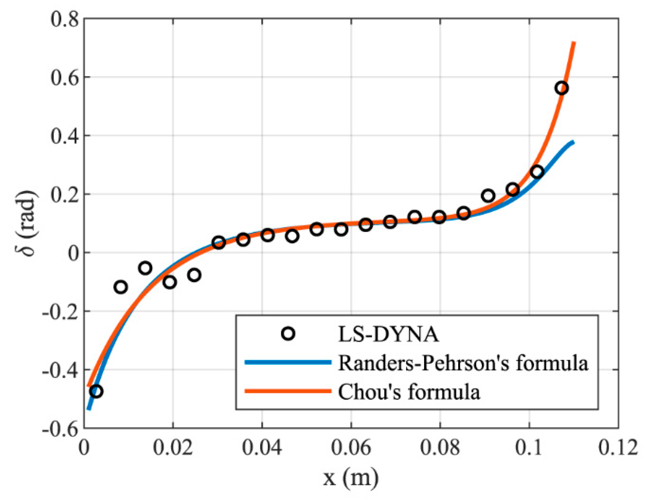
In the prediction of the projection angle, the fitting results of Randers-Pehrson’s Formula (2) and Chou’s Formula (3) are shown in Figure 4. The fitting effect of Chou’s equation was consistent with that of Randers-Pehrson’s at the middle position of the charge, although it was better at the end, as mentioned above. Therefore, the fitted formula of Chou was preferred for predicting the projection angle of the fragments, which can be expressed as
δ = V 0 2 U 1 2 ( 1.405 × 10 5 ) V 0 + 1 4 ( 5.061 × 10 6 ) V 0

3. Damage Mechanism of the Phased-Array Antenna

The phased-array radar antenna consists of numerous array elements, which can perform beam scanning by controlling the phase offset between adjacent array elements. It is feasible to consider the attenuation index of antenna performance as the evaluation criterion for warhead damage assessment as it can either continue to work normally or be affected only slightly when a certain number of array elements fail. In the theoretical analysis of phased-array antenna, the mutual coupling effect between array elements is usually ignored. The electrical performance of a phased-array antenna is mainly characterized by the array factor pattern.

3.1. Mathematical Model of the Antenna Pattern

A planar phased-array antenna Z ( n , m ) was considered with N × M array elements distributed on a regular grid on the x-y plane, as illustrated in Figure 5a. It was thought to be steered in elevation and azimuth ( θ , φ ), as illustrated in Figure 5b. The element spacing along the x- and y-directions are, respectively, denoted by d x and d y . The direction cosine of the beam direction angle is ( cos α x , cos α y , cos α z ) . The spatial step-phase difference between x- and y-directions can be expressed as
ϕ x = k d x cos α x = k d x sin θ cos φ ϕ y = k d y cos α y = k d y sin θ sin φ
where k is the wavenumber (2π/wavelength). In drawing the direction diagram, it is very common to express a planar array’s ability of the directional cosines ( u , v ) to steer the beam in space in terms of the u-v space instead of the angles ( θ , φ ). The directional cosines are expressed as
u = sin θ cos φ v = sin θ sin φ
The in-array phase difference between adjacent elements of the antenna in the x- and y-directions is denoted as α and β , respectively, which can be adjusted for phase-controlled scanning of the antenna beam. The pattern function of the phased-array antenna element can be expressed as [30]:
F ( θ , φ ) = a ( n , m ) S ( n , m ) × n = 0 N 1 e j n ( ϕ x α ) m = 0 M 1 e j m ( ϕ y β )
where a ( n , m ) is the amplitude weight of the ( n , m ) element and S ( n , m ) indicates the pattern radiated by the ( n , m ) element. In the transmitting mode, all the array elements were uniformly weighted with the maximum power to ensure the maximum power range. While in the receiving mode, a certain weighting algorithm needed to be applied to ensure low sidelobe characteristics. The windowing method is the commonly used weighting algorithm, such as in Hanning, Hamming, Kaiser, and Dolph–Chebyshev windows, etc. [31]. The window is represented by a weight matrix w [ n , m ] that consists of elements a ( n , m ) . It was assumed that the failed element ( n , m ) did not contribute to radiation and was implemented by setting a ( n , m ) = 0 . It is often assumed that the antenna elements are homogenous and the mutual coupling effect between the elements is omitted in the analysis of the phased-array antenna—that is, S ( n , m ) = 1 .
The phased-array antenna pattern synthesis was calculated by inverse fast Fourier transform (FFT), which can be simply implemented in MATLAB and exhibits considerably high computational speed.

3.2. Performance Index of the Phased-Array Antenna

The tactical indexes of phased-array radar include the power range, accuracy, resolution, anti-interference ability, and signal processing performance, among others. The attenuation values of these tactical indicators after damage are difficult to quantify directly; however, they can be described indirectly through changes in the electrical performance indicators. When the antenna array is damaged and some elements fail, electrical performance indexes, such as the maximum radiation gain, sidelobe level, and beamwidth, will change correspondingly, thereby affecting the tactical indexes. The evaluation indexes of the tactical performance of radars with different functions should be analyzed accordingly. This study took the maximum radar range, which is one of the power range indexes, as an example, which could be quantified by the radar Equation [30]:
R max = [ P t G 2 λ 2 σ ( 4 π ) 3 S i min L ] 1 / 4
where P t is the peak transmitted power, G is the antenna gain, λ is the wavelength, σ is the radar cross-section, S i min is the minimum detectable signal, and L is the radar loss. Among the above parameters, the values of P t and G are directly related to the element failure, whereas the values of other parameters are determined by the performance of the signal processor, target characteristics, etc. For array antennas, P t and G can be expressed as
P = ω m = 0 M 1 n = 0 N 1 | a ( m , n ) S ( m , n ) | 2 G = 4 π | m = 0 M 1 n = 0 N 1 a ( m , n ) S ( m , n ) | 2 ω m = 0 M 1 n = 0 N 1 | a ( m , n ) S ( m , n ) | 2
where ω is the ratio of the array element power to the square of the excitation amplitude.
Moreover, the anti-interference capability of the phased-array antenna is related to the low secondary lobes, which can be characterized by the first sidelobe level (FSLL) [32], and the angular resolution capability is related to the narrow beamwidth, which can be characterized by the half-power beamwidth (HPBW), namely, the 3-dB beamwidth. Both FSLL and HPBW can be calculated from the phased-array antenna pattern.

4. Evaluation of Damage Effect

4.1. Projectile Intersection Model Based on the Shot Line

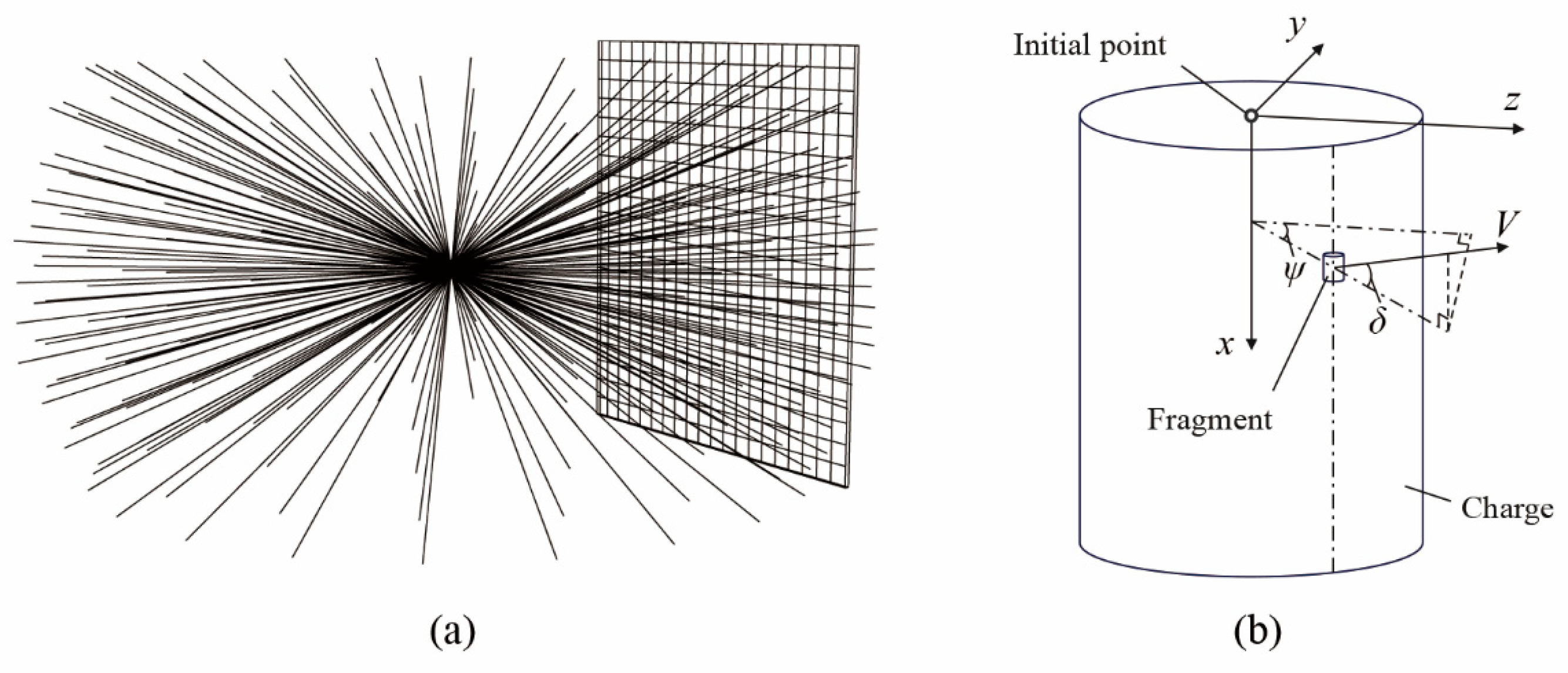
Because a numerical simulation of the damage field incurs a considerable cost, thereby not meeting the real-time requirements of battlefield evaluation and decision-making, rapid calculation of the shot line is required [33]. The trajectories of all fragments calculated by the prediction formula proposed in Section 2.1 were traversed to establish the shot-line model of the fragments and the global spatial coordinates, as illustrated in Figure 6. The spatial coordinate of fragment ( p , q ) centroid was ( x p q , y p q , z p q ) . The projection angles of the pitch and azimuth were δ p q and ψ p q , respectively. The shot-line model of the fragment can be expressed as
{ x = ( z z p q ) cos ψ p q tan ( δ p q ) + x p q y = ( z z p q ) tan ( ψ p q ) + y p q
When the fragments intersect the target antenna, they need to penetrate the protective radome over the array element, causing damage to the internal array element components. When the fragment velocity reaches the anti-penetration limit velocity of the radome, the corresponding array element fails. The anti-penetration limit velocity of the radome varies with the mechanical properties and dimensions of the radome, which can be obtained by further specialized studies utilizing ballistics tests and numerical simulations [34]. In this study, we considered the ideal situation––that is, all fragments hitting the target antenna could cause effective damage against the elements.

4.2. Analysis and Discussion of Examples

To indicate the functional attenuation when the antenna is subjected to damage of the preformed fragment LYPGW described in Section 2, we devised the following test scenario. A 40 × 40 rectangular planar phased-array antenna with d x , d y , λ = 0.1, 0.1, 0.2 m was considered. Uniform weighting was used in the transmitting mode and the hamming window weighting was used in the receiving mode. Thus, the maximum radar range only depended on the number of valid elements in the transmitting mode. Other properties were determined by the receiving pattern.
First, we placed the warheads in the center of the antenna front and considered the effect of explosion distance, as shown in Figure 7, which can directly reflect the distribution of failure elements. The calculation results of the damage assessment model with explosion distances of 1 m, 3 m, 5 m, and 7 m were compared with those in normal operation (Case 0), with no element damaged.
The variation of the maximum radar range under different explosion distances is shown in Table 5. The results showed that the impact on the maximum radar range was not significant because of the limited density of fragmentation damage elements.
The values of other electrical performance parameters in transmitting and receiving modes are shown in Table 6 and Table 7, respectively. Compared with the transmitting pattern with window weighting, the receiving pattern with uniform weighting had a narrower HPBW, thus ensuring angle resolution. The fragmentation damage did not widen the HPBW because it did not affect the aperture of the antenna array. It is evident from Figure 8 that the FSLL was significantly lifted in the receiving mode, optimized by amplitude weighting for low sidelobe characteristics due to fragmentation damage. Even if the warhead explodes at a relatively long distance, sparse fragments can also cause the sidelobe to rise and the null steering to deviate, resulting in serious failure.
To further study the effect of the position of the failure elements on the electrical performance of the antenna, we set the same number of failure elements, namely, 30%, and distributed the failure elements in four different conditions: center, marginal center, uniform edge, and edge ends, as shown in Figure 9. This distribution of failure elements can simulate the local damage caused by the shock wave in a close explosion. Other working conditions were consistent with those mentioned above. The calculation results in the transmitting and receiving modes are shown in Table 8 and Table 9, respectively, and the receiving pattern is shown in Figure 10. It can be concluded from the results that the influence on the FSLL was most significant in the receiving mode when the failure elements were at the center, while the HPBW was narrowed to a certain extent in the transmitting mode. However, in actual combat, it is difficult for the LYPGW to approach the center of the array due to the strong electronic radiation of the phased-array radar. Under such a constraint, three edge failure modes (Cases 6–8) were compared. Failure elements at the marginal center (Case 6) were more effective for raising the FSLL in both the u- and v- directions in the receiving mode, while those at the uniform edge were more effective for broadening HPBW in the transmitting mode. Moreover, it can be concluded through Case 6–8 that when the failure elements are distributed along the y-axis edge, the HPBW is broadened mainly in the u- direction in both the transmitting and receiving modes. The conclusion above is beneficial for allowing the LYPGW to effectively exert the damage power of the shockwave in a close explosion.

5. Conclusions

This study proposed a rapid calculation method for the functional damage effect assessment for preformed fragment warheads on the electrical performance of a phased-array antenna. The attenuation of the electrical performance index of the phased-array antenna under the failure conditions was quantified. The LYPGW can effectively cause functional damage to the phased-array antenna through fragmentation of the fragments at a relatively long explosive distance, while the damage of the center and the marginal center of the phased-array antenna should be concentrated when the damage power of a single warhead is limited. This co-simulation method of studying the effect of failed elements on the performance of the antenna has more tactical application value than the structural damage assessment method with equivalent targets and the electrical simulation in artificial or random phrased-array-element failure conditions.

Author Contributions

Conceptualization, W.G.; methodology, S.Z. and L.H.; software, Z.C. and S.Z.; formal analysis, S.Z. and L.H.; investigation, S.Z., C.S., L.H. and W.R.; resources, C.S. and W.R.; writing—original draft, S.Z.; writing—review and editing, W.G.; supervision, C.S. and W.R.; project administration, W.G. All authors have read and agreed to the published version of the manuscript.

Funding

This research was funded by the National Defense Science and Technology Innovation Program (193-A14-220-01).

Institutional Review Board Statement

Not applicable.

Informed Consent Statement

Not applicable.

Data Availability Statement

Not applicable.

Conflicts of Interest

The authors declare no conflict of interest.

References

  1. Mets, D.R. The Long Search for a Surgical Strike: Precision Munitions and the Revolution in Military Affairs; CADRE Paper; Air University Press: Montgomery, Alabama, 2001. [Google Scholar]
  2. Gillespie, P.G. Weapons of Choice: The Development of Precision Guided Munitions; University of Alabama Press: Tuscaloosa, Alabama, 2006; ISBN 978-0-8173-1532-0. [Google Scholar]
  3. Liu, F.; Shi, Q.; Wang, G.; Zhang, B. Simulation on the Planar Array Antenna Penetrated to Tungsten Spherical Fragment. Adv. Mater. Res. 2013, 753–755, 1060–1064. [Google Scholar] [CrossRef]
  4. Lv, Y.; Shi, Q.; Wang, G.; Liu, F.; Xu, Y.; Li, G.; Zou, X. Dynamic Finite-Element Simulation on the Phased Array Radar Antenna Multiplex Damage by Fragment and Shock Wave. In Proceedings of the 2012 International Conference on Quality, Reliability, Risk, Maintenance, and Safety Engineering (icqr2mse), Chengdu, China, 15–18 June 2012; Huang, H.Z., Zuo, M.J., Liu, Y., Eds.; IEEE: New York, NY, USA, 2012; pp. 929–933. [Google Scholar]
  5. Li, X.; Xiang, X.; Huang, G.; Feng, S. Penetration Characteristics of Tungsten Sphere Fragment to Typical Components of Phased Array Radar. Acta Armamentarii 2010, 31, 51–56. [Google Scholar]
  6. Gurney, R.W. The Initial Velocities of Fragments from Bombs, Shells and Grenades; BRL Report; Ballistic Research Laboratories: Aberdeen, MD, USA, 1943. [Google Scholar]
  7. Taylor, G.I. Analysis of the Explosion of a Long Cylindrical Bomb Detonated at One End. In The Scientific Papers of Sir Geoffrey Ingram Taylor; Cambridge University Press: Cambridge, UK, 1941; Volume 3, pp. 277–286. [Google Scholar]
  8. Randers-Pehrson, G. An Improved Equation for Calculating Fragment Projection Angle. In Proceedings of the 2nd International Symposium on Ballistics, Datona Beach, FL, USA,, 9–11 March 1976; International Ballistic Society. American Defense Preparedness Association: Arlington, VA, USA, 1976; pp. 223–226. [Google Scholar]
  9. Charron, Y.J. Estimation of Velocity Distribution of Fragmenting Warheads Using a Modified Gurney Method; Air Force Institute of Technology Wright-Patterson AFB OH School of Engineering: Dayton, OH, USA, 1979. [Google Scholar]
  10. Zulkoski, T. Development of Optimum Theoretical Warhead Design Criteria; Naval Weapons Center China Lake: Kern County, CA, USA, 1976. [Google Scholar]
  11. Chou, P.C.; Carleone, J.; Flis, W.J.; Ciccarelli, R.D.; Hirsch, E. Improved Formulas for Velocity, Acceleration, and Projection Angle of Explosively Driven Liners: Velocity, Acceleration, and Projection Angle of Liners. Propellants Explos. Pyrotech. 1983, 8, 175–183. [Google Scholar] [CrossRef]
  12. Huang, G.; Li, W.; Feng, S. Axial Distribution of Fragment Velocities from Cylindrical Casing under Explosive Loading. Int. J. Impact Eng. 2015, 76, 20–27. [Google Scholar] [CrossRef]
  13. Felix, D.; Colwill, I.; Harris, P. Real-Time Calculation of the Initial Angle of Projection for Fragments in Cylindrical Warheads. J. Def. Model. Simul. 2021, 19, 154851292098267. [Google Scholar] [CrossRef]
  14. Jiang, N.; Li, W.; Yao, W.; Gao, D. Calculation Model of the Axial Dispersion Distribution of Cylindrical-Warhead Fragments. Shock. Vib. 2022, 2022, 3144545. [Google Scholar] [CrossRef]
  15. Grisaro, H.; Dancygier, A.N. Numerical Study of Velocity Distribution of Fragments Caused by Explosion of a Cylindrical Cased Charge. Int. J. Impact Eng. 2015, 86, 1–12. [Google Scholar] [CrossRef]
  16. Zhu, S.; Cai, J.; Han, C.; An, T.; Qu, L. Influence of Failed Element on Array Antenna Performance. Electron. Opt. Control. 2019, 26, 54–59. [Google Scholar]
  17. Zhang, H.; Dong, S.; Bo, L. Damage Analysis of Planar Phased Array Antenna. Radar Sci. Technol. 2017, 15, 322–326+333. [Google Scholar]
  18. Xiong, S.; Lyu, X.; Duan, J. Damage Analysis of Shipborne Phased Array Radar Antenna. Missiles Space Veh. 2020, 5, 92–98. [Google Scholar]
  19. Liu, Y.; Zhou, L.; Wang, N. Assessment of Combined Damage to the Phased Array Antenna by Shock Wave and Fragments. Prot. Eng. 2021, 43, 35–40. [Google Scholar]
  20. Keizer, W.P.M.N. Element Failure Correction for a Large Monopulse Phased Array Antenna with Active Amplitude Weighting. IEEE Trans. Antennas Propagat. 2007, 55, 2211–2218. [Google Scholar] [CrossRef]
  21. Poli, L.; Rocca, P.; Oliveri, G.; Massa, A. Failure Correction in Time-modulated Linear Arrays. IET Radar Sonar Navig. 2014, 8, 195–201. [Google Scholar] [CrossRef]
  22. Muralidharan, R.; Vallavaraj, A.; Mahanti, G.K.; Patidar, H. QPSO for Failure Correction of Linear Array of Mutually Coupled Parallel Dipole Antennas with Desired Side Lobe Level and Return Loss. J. King Saud Univ. -Eng. Sci. 2017, 29, 112–117. [Google Scholar] [CrossRef]
  23. Patidar, H.; Mahanti, G.K.; Muralidharan, R.; Singh, P.K. Failure Correction of a Linear Array of Coupled Parallel Vertical Dipole Antennas. J. Telecommun. Inf. Technol. 2020, 1, 62–69. [Google Scholar] [CrossRef]
  24. Kong, X.; Wu, W.; Li, J.; Liu, F.; Chen, P.; Li, Y. A Numerical Investigation on Explosive Fragmentation of Metal Casing Using Smoothed Particle Hydrodynamic Method. Mater. Des. 2013, 51, 729–741. [Google Scholar] [CrossRef]
  25. Wang, L.; Han, F.; Zhou, Q. The Projection Angles of Fragments from a Cylindrical Casing Filled with Charge Initiated at One End. Int. J. Impact Eng. 2017, 103, 138–148. [Google Scholar] [CrossRef]
  26. Hao, L.; Gu, W.; Zhang, Y.; Yuan, Q.; Xie, X.; Zou, S.; Wang, Z.; Lu, M. Damage of a Large-Scale Reinforced Concrete Wall Caused by an Explosively Formed Projectile (EFP). Def. Technol. 2022. [Google Scholar] [CrossRef]
  27. Hu, F.; Wu, H.; Fang, Q.; Liu, J. Numerical Simulations of Shaped Charge Jet Penetration into Concrete-like Targets. Int. J. Prot. Struct. 2017, 8, 237–259. [Google Scholar] [CrossRef]
  28. Boslashrvik, T.; Dey, S.; Clausen, A.H. Perforation Resistance of Five Different High-Strength Steel Plates Subjected to Small-Arms Projectiles. Int. J. Impact Eng. 2009, 36, 948–964. [Google Scholar]
  29. Keshavarz, M.H. New Method for Prediction of the Gurney Energy of High Explosives. Propellants Explos. Pyrotech. 2008, 33, 316–320. [Google Scholar] [CrossRef]
  30. Mahafza, B.; Elsherbeni, A. MATLAB Simulations for Radar Systems Design; CRC Press: Boca Raton, FL, USA, 2004; p. 682. ISBN 978-1-58488-392-0. [Google Scholar]
  31. Mottaghi-Kashtiban, M.; Shayesteh, M.G. New Efficient Window Function, Replacement for the Hamming Window. IET Signal Process. 2011, 5, 499. [Google Scholar] [CrossRef]
  32. Ramsdale, D.J.; Howerton, R.A. Effect of Element Failure and Random Errors in Amplitude and Phase on the Sidelobe Level Attainable with a Linear Array. J. Acoust. Soc. Am. 1980, 68, 901–906. [Google Scholar] [CrossRef]
  33. Qian, L.; Liu, T.; Zhang, S.; Yang, Y. Fragment Shot-Line Model for Air-Defence Warhead. Propellants Explos. Pyrotech 2000, 25, 92–98. [Google Scholar] [CrossRef]
  34. Chen, X.; Zhu, X.; Zhang, L.; Wang, X. Design and Properties of Sandwich Structure for Ballistic-Resistant Radome. Acta Armamentarii 2010, 32, 1298–1302. [Google Scholar]
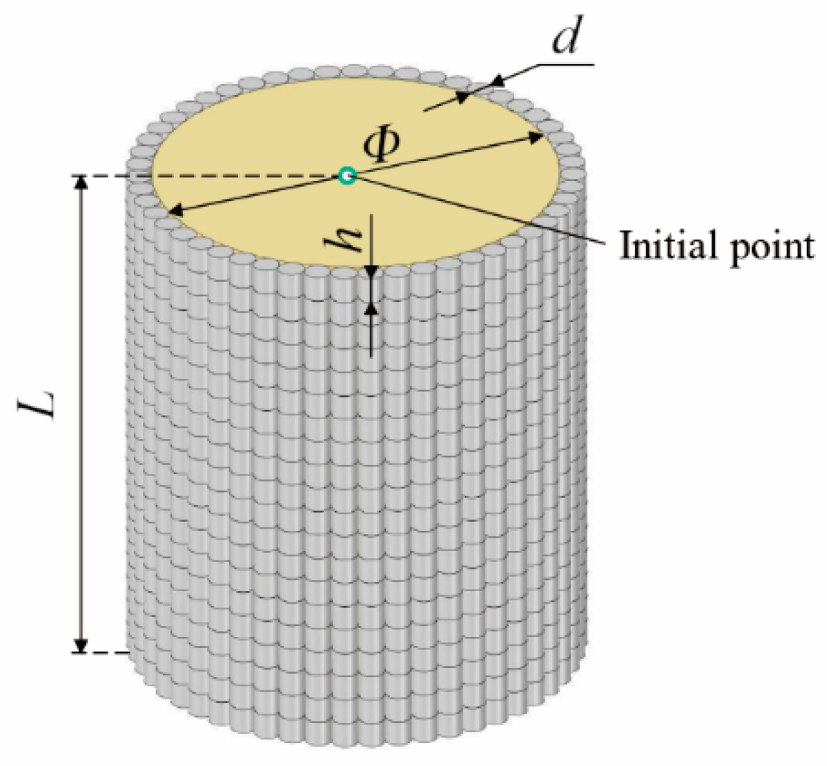
Figure 1. Schematic geometry of the preformed fragment LYPGW.
Electronics 12 01907 g001
Figure 2. Simulation results: (a) Projection distribution of the fragments along the axial at t = 0 us, 20 us, 40 us, 60 us, 80 us, 100 us and 120 us. (b) Velocity curves of the fragments in (a) with color correspondence.
Electronics 12 01907 g002
Figure 3. Initial velocity fitting result.
Electronics 12 01907 g003
Figure 4. Projection angle fitting result.
Electronics 12 01907 g004
Figure 5. Diagrams of the rectangular planar phased-array antenna. (a) Array elements. (b) Coordinate system.
Electronics 12 01907 g005
Figure 6. Illustrations of the shot-line model (a) and the global spatial coordinates (b).
Electronics 12 01907 g006
Figure 7. Failure diagrams of the phased-array antenna at different explosion distances: (a) 1 m, (b) 3 m, (c) 5 m, (d) 7 m.
Electronics 12 01907 g007
Figure 8. 3D (a) and 2D patterns (b) of the phased-array antenna in the receiving mode at different explosion distances.
Electronics 12 01907 g008
Figure 9. Failure diagrams of the phased-array antenna in different distribution conditions: (a) center, (b) marginal center, (c) uniform edge, (d) edge ends.
Electronics 12 01907 g009
Figure 10. 3D (a) and 2D patterns (b) of the phased-array antenna in receiving mode in different failure elements distribution conditions.
Electronics 12 01907 g010
Table 1. Geometric dimensions of the preformed fragment LYPGW.
Charge Diameter Φ (mm)Charge Length L
(mm)
Fragment Diameter d
(mm)
Fragment Length h (mm)
851100.40.4
Table 2. MAT_NULL material model and EOS_LINEAR_POLYNOMIAL parameters of the air [26].
ρ
(kg/m3)
C0–C3
(Pa)
C4
(Pa)
C5
(Pa)
C6
(Pa)
E0
(Pa)
V0
1.22500.40.402.5 × 1051
Table 3. MAT_HIGH_EXPLOSIVE_BURN material model and EOS_JWL parameters of the JH-2 [27].
ρ
(kg/m3)
D
(m/s)
PCJ
(GPa)
A
(GPa)
B
(GPa)
R1
R2
ωE0
(GPa)
V0
1710789028.6524.27.7684.21.10.348.51
Table 4. MAT_RIGID material model of the Q235 steel [28].
ρ
(kg/m3)
E
(GPa)
ν
78502100.33
Table 5. Transmitting parameters at different explosion distances in the transmitting mode.
CaseExplosion Distance
(m)
Number of Failed ElementsMaximum Radar Range Decay Rate
(%)
0-00
111959.29
231175.54
35964.53
47693.25
Table 6. Electrical performance parameters at different explosion distances in the transmitting mode.
CaseExplosion Distance
(m)
Mainlobe Gain
(dB)
FSLL in u- Direction
(dB)
FSLL in v- Direction
(dB)
HPBW in u- Direction
(°)
HPBW in v- Direction
(°)
0-32.04−13.27−13.273.523.52
1131.48−11.77−9.433.523.52
2331.71−13.05−11.823.523.52
3531.77−13.20−12.333.523.52
4731.85−13.31−12.983.523.52
Table 7. Electrical performance parameters at different explosion distances in the receiving mode.
CaseExplosion Distance
(m)
Mainlobe Gain
(dB)
FSLL in u- Direction
(dB)
FSLL in v- Direction
(dB)
HPBW in u- Direction
(°)
HPBW in v- Direction
(°)
0-29.19−42.00−42.005.635.63
1128.59−19.75−14.454.924.92
2328.76−18.73−26.925.635.63
3528.89−22.37−31.775.635.63
4728.99−25.66−34.025.635.63
Table 8. Electrical performance parameters in the transmitting mode in different failure elements distribution conditions.
CaseFailure Elements Distribution PositionMainlobe Gain
(dB)
FSLL in u-
Direction
(dB)
FSLL in v-
Direction
(dB)
HPBW in u-
Direction
(°)
HPBW in v-
Direction
(°)
5Center30.49−6.50−8.042.812.81
6marginal center30.49−11.72−8.044.222.81
7uniform edge30.49−13.23−13.275.633.52
8edge ends30.49−14.54−14.644.924.22
Table 9. Electrical performance parameters in the receiving mode in different failure elements distribution conditions.
CaseFailure Elements Distribution PositionMainlobe Gain
(dB)
FSLL in u-
Direction
(dB)
FSLL in v-
Direction
(dB)
HPBW in u-
Direction
(°)
HPBW in v-
Direction
(°)
5center28.26−7.23−13.553.524.22
6marginal center27.10−22.36−22.407.734.92
7uniform edge28.04−25.10−42.007.035.63
8edge ends28.02−27.22−30.036.336.33
Disclaimer/Publisher’s Note: The statements, opinions and data contained in all publications are solely those of the individual author(s) and contributor(s) and not of MDPI and/or the editor(s). MDPI and/or the editor(s) disclaim responsibility for any injury to people or property resulting from any ideas, methods, instructions or products referred to in the content.