Abstract
The spectrum sensing that jointly estimates direction-of-arrival (DOA) and frequency spectrum is an important issue for cognitive radio. Existing off-grid DOA estimation algorithms using difference coarray require a large number of snapshots to guarantee the estimation accuracy. Meanwhile, inaccurate DOA estimation renders inaccurate frequency spectrum estimation due to coupled estimation process. In order to overcome these disadvantages, we propose a joint angle and frequency spectrum estimation algorithm using difference coarray in this work. The proposed algorithm first transforms the received signal into the coarray domain and then adopts an “estimate and subtract” method to separate multiple signals. Subsequently, the DOA estimate of each source is corrected iteratively based on the proposed simple interpolation method. Finally, the frequency spectra are obtained by estimating the frequency response matrix based on the previous estimated DOAs. The shortage of requiring a large number of snapshots are overcome by utilizing the deterministically orthogonal signal model in which the signals are completely uncorrelated. Simulation results demonstrate the effectiveness of the proposed algorithm for off-grid DOA and frequency spectrum estimation using difference coarray with few snapshots.
1. Introduction
Spectrum sensing that simultaneously estimates direction-of-arrival (DOA) and frequency spectrum is an important subject in signal processing [1,2,3,4,5]. The combination of angle and frequency spectrum estimation results is beneficial to radar and communication equipment for target detection or data transmission [6,7,8].
DOA estimation has been intensively studied for decades. When the source number is more than antenna elements, many traditional off-grid DOA estimation algorithms can not work [9,10,11,12,13,14,15,16,17,18,19,20,21,22,23,24]. The sparse linear arrays can estimate more sources than the number of sensors by exploiting the difference coarray formulated by vectorizing the sample covariance matrix [9,10]. In [9], nested array was proposed and spatial smoothing multiple signal classification (MUSIC) was adopted based on the difference coarray. An approach which simultaneously utilize low rank matrix denoising and subspace based methods was proposed in [11], where the nuclear norm was exploited to underdetermined DOA estimation. In [12], an interpolation-based method based on virtual array was developed to form the interpolated array covariance matrix by solving an atomic norm minimization problem. In [13], an augmented covariance matrix reconstruction method was presented based on maximum-likelihood approach by exploiting Toeplitz structure property. The concept of Wasserstein distance was introduced in [14] to formulate augmented covariance matrix. More sources can be distinguished based on the augmented covariance matrix. An off-grid DOA estimation algorithm based on block sparse representation was proposed in [15] to estimate the location of strictly noncircular sources utilizing an transformed nested array. In addition, various off-grid DOA estimation methods suitable for arbitrary physical linear arrays, such as search-based method and enhanced principal-singular-vector utilization for modal analysis (EPUMA), also can be applied for DOA estimation using difference coarray [16,17]. However, all these methods have a significant demand for a large number of snapshots for coarray-based DOA estimation.
Frequency is another critical parameter in array signal processing. The combined estimation of frequency and DOA has been widely studied [25,26,27,28,29,30,31,32,33,34,35,36]. The estimation of signal parameters using rotational invariance techniques (ESPRIT) based algorithms were proposed in [25,26] with low computational complexity. An effective frequency-angle spectrum hole detection algorithm was developed in [27] by utilizing Taylor expansion. Moreover, the real-valued parallel factor (PARAFAC) method was introduced in [28] to improve the estimation accuracy. A spur of sub-Nyquist sampling methods, such as modulated wideband converter [29], co-prime sampling [30,31] and multi-coset sampling [32] were proposed in the literature. The block vectorization was introduced in [33] to eliminate the interference caused by sub-Nyquist sampling and then a novel sample covariance matrix was reconstructed to identify more sources. The iterative adaptive algorithm (IAA) was developed to select angle-frequency grid [34]. A regularized maximum likelihood estimation paradigm based approach utilizing the sparsity characteristic of the profile was proposed in [35] to perform angle estimation and spectrum sensing. An angle-frequency distribution estimation method was proposed in [36] based on spatial-temporal sparse sampling. It is worth noting that the estimation accuracy of angle and frequency influence each other due to coupled estimation process.
The motivation of this work is to propose an accurate joint angle and frequency spectrum estimation algorithm using difference coarray while avoiding the aforementioned drawbacks. The contributions of this paper are listed as follows: (i) An iterative correction method for DOA and signal power is exploited to enhance DOA estimation accuracy and a simple interpolation method is proposed to estimate DOAs by finding the global optimal solutions of the optimization problem; (ii) A frequency spectrum estimation algorithm is proposed by computing the frequency response matrix based on estimated DOAs and high precision estimation of DOAs guarantees the estimation performance of frequency spectrum; (iii) The demand of lots of snapshots for DOA estimation using difference coarray is overcome by introducing the deterministically orthogonal signal model in which the signals are completely uncorrelated; (iv) We verify the estimation performance of the proposed method via comprehensive simulations.
The remainder of the paper is organized as follows. The signal model of off-grid DOA and frequency spectrum estimation based on difference coarray is provided in Section 2. Section 3 introduces the proposed angle and frequency spectrum estimation method. Section 4 presents the simulation results to validate the effectiveness of the proposed technique. The concluding remarks are given in Section 5.
2. Signal Model
The positions of a linear array elements are given by,
where , are integer numbers and is the unit inter-element spacing. The positions of corresponding difference coarray can be represented as,
From Equation (2), we can see that the difference coarray can be obtained by differences between any two element positions [37,38,39].
K far-field narrow-band sources are arriving from directions . The received signal can be written as,
where the source vector is . The signals are deterministically orthogonal and the source covariance matrix is a diagonal matrix. The noise vector is a zero-mean, complex white Gaussian process with power . The array manifold matrix is given by , where is the array steering vector .
The covariance matrix of the received signal can be expressed as,
Vectorizing the covariance matrix and we have
where and with each column given by,
Here, ⊗ denotes the Kronecker product.
Note that a virtual array with large size can be constructed by vectorization operations and the column vector can be regarded as the received data from the virtual array. Each entry of the vector denotes the power of each source and the deterministic noise is obtained by vectorizing the identity matrix.
In practice, the sample covariance matrix is used instead of with T snapshots.
Vectorizing the sample covariance matrix, we obtain
where is the estimation error caused by limited samples.
Then the real-valued vector can be obtained by left multiplying a matrix , that is [40],
where is an matrix with entries being or . The real part and imaginary part of each element in can be expressed as,
Consider M uniform sampling grid points in the search region . The grid interval is set as . The DOAs of the sources offset the predefined grid points. We propose a new algorithm for off-grid DOA estimation and frequency spectrum estimation, which is described in detail in the following section.
3. The Proposed Method
3.1. DOA Estimation
Various traditional methods, such as conventional beamforming and root-MUSIC, can be exploited for initial DOA estimation. From the point view of simplifying computational complexity, conventional beamforming is utilized to obtain the initial DOA estimates. Define a normalized beamforming matrix and its -th element is . An output vector can be obtained by conventional beamforming, that is . The location of the largest peak can be obtained and the corresponding initial DOA estimate of the kth signal is given by,
Approximating the estimated DOA to the nearest grid point by conventional beamforming can not guarantee the estimation accuracy. To tackle this problem, iterative correction of DOAs and signal power is conducted following the initial estimation, which is detailed in the following.
The spectrum leakage from other sources affects the DOA estimation of the kth source and the estimate-subtract method is utilized to eliminate the effect of spectrum leakage [41].
Suppose that there are signals, where is an intermediate value. The kth signal vector can be isolated by subtracting other signals from the data, that is,
where we assume that have been obtained from last iteration. Then and can be estimated by solving the following minimization problem, that is,
For fixed , can be estimated by solving Equation (13) as,
Substituting Equation (14) into Equation (13), the DOA estimate of the kth source is given by,
where .
Note that the minimization problem of Equation (15) is easily affected by the selection of initial point position. Therefore, the DOA estimate is utilized as the initial value to ensure the quality of the solution. A series of traditional algorithms, such as gradient descent method and Newton method, can be utilized to solve the problem. However, these algorithms can not guarantee the unique global optimal solution [42]. This motivates us to introduce a simple interpolation method for solving the above optimization problem.
(1) Fit a convex function to three points which are () and its two neighbor points. Here, () is the point corresponding to the kth source and is the criterion function in Equation (15) evaluated at .
(2) Take the minimum of the function as the next grid point and evaluate the criterion function at that point.
(3) Fit a new function again utilizing the minimum together with its two neighbor points.
(4) Iterate the above steps and terminate the algorithm when the convergence condition is satisfied. Here, is a user-defined tolerance and h refers to the iteration.
It should be noted that zero padding is adopted in the RELAX algorithm to improve the estimation performance. However, angle correction procedure is exploited in the proposed method instead of zero padding which is different from RELAX.
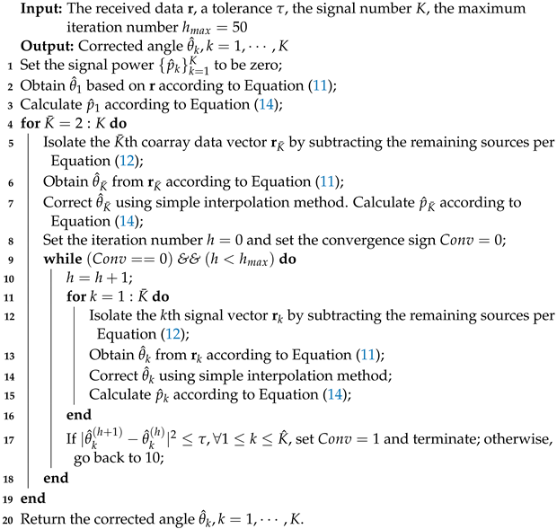
Assume that the signal number K is already estimated. The detailed steps of the proposed algorithm are given below.
Step 1: Let . Obtain from ( in this step) using conventional beamforming according to Equation (11). Calculate with Equation (14).
Step 2: Let . Compute per Equation (12) based on and estimated in Step 1. Obtain from with Equation (11). Correct using simple interpolation method. Calculate with Equation (14).
Next, compute per Equation (12) based on and . Correct using simple interpolation method. Calculate according to Equation (14).
Iterate the above two substeps and terminate when the convergence condition is satisfied.
Step 3: Let . Compute with Equation (12) using . Obtain from using conventional beamforming according to Equation (11). Correct using simple interpolation method. Calculate with Equation (14).
subsequently, compute per Equation (12) based on . Correct using simple interpolation method. Calculate with Equation (14).
subsequently, compute per Equation (12) based on . Correct using simple interpolation method. Calculate with Equation (14).
Iterate the above substeps and terminate when the convergence condition is satisfied.
Remaining Steps: Repeat the above steps until equals the estimated signal number .
The detailed content of the proposed off-grid DOA estimation algorithm is provided in Algorithm 1. The proposed algorithm includes two layers of loop, that is outer and inner loop. In the outer loop, the angle information of estimated sources is utilized to estimate the angle of a new source and the number of estimated signals is increased by one each time. In the inner loop, the DOA estimates are corrected iteratively. The current estimated signal is separated in the kth iteration and then the proposed simple interpolation method is exploited to obtain the accurate angle. It is worth noting that the algorithm terminates when the maximum difference of DOA estimates obtained by two consecutive loops is less than the tolerance .
3.2. Frequency Spectrum Estimation
Proceeding from Equation (3), the matrix form of the received data can be modeled as multiple measurement vectors with T snapshots, expressed as,
where , and and are similarly defined.
The frequency domain information of the signal will be investigated by the data collected with T snapshots. Define a matrix and its -th element is . The columns of can be viewed as series of bases and can be given by,
where the frequency response matrix . To obtain frequency spectrum given the received data , we propose a frequency response matrix estimation method in the following.
Applying vectorization to , and , that is, , , , then we can obtain
Define the matrix with . Here, can be estimated using Algorithm 1. The problem of estimating the vector can be formulated as,
The minimization problem of Equation (19) is solved using the least squares technique and the solution is given by,
According to the relationship between the vector and the matrix , that is , the frequency response matrix can be obtained.
| Algorithm 1: The proposed algorithm for off-grid DOA estimation. |
 |
4. Simulation Results
We conduct the comprehensive simulation to verify the effectiveness of the proposed algorithm in this section.
Consider a nested array comprising antennas. The nested array configuration is given in Figure 1. The coarray of the nested array is a 39-antenna uniform linear array. Consider 180 sampling grids and grid interval is set as .

Figure 1.
The 8-antenna nested array. Circles indicate selected antenna positions, while crosses discarded.
In order to investigate the estimation accuracy of the proposed algorithm, the root mean square error (RMSE) is utilized as a metric, that is,
The estimation performance of search-based algorithm, EPUMA and the proposed method are compared. The RMSE versus signal to noise ratio (SNR) with four off-grid sources arriving from in the case of different numbers of snapshots are depicted in Figure 2. The search interval of angle offset is in the search-based algorithm. The snapshots number is set as 20 and 500 respectively. 200 Monte-Carlo trials are implemented to calculate the RMSE. The Cramér-Rao Bound (CRB) curves are also depicted. The RMSE of the proposed method can approaching the CRB when SNR reaches a certain value in both cases of few and more snapshots scenarios. The proposed algorithm exhibits a higher estimation accuracy than search-based algorithm in the considered cases. The RMSE of search-based algorithm can not reach the CRB even in the case of large number of snapshots due to the limited search interval of the angle offset. Note that the SNR required by the proposed algorithm to reach the CRB is lower than that of EPUMA.
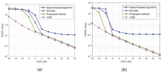
Figure 2.
RMSE of three methods versus SNR with four off-grid sources in the case of different numbers of snapshots: (a) 20 snapshots. (b) 500 snapshots.
To further investigate the estimation accuracy when the source number is more than array element number, search-based algorithm, EPUMA and the proposed method are utilized for comparison. The RMSE of these three methods versus SNR with ten off-grid sources arriving from in the case of different numbers of snapshots are provided in Figure 3. The search interval settings of angle offset are the same with that in Figure 2. The snapshots number is set as 20 and 500 respectively. 200 Monte-Carlo runs are utilized. The CRB curves are also displayed. We can observe that the estimation performance of the proposed algorithm is higher than that of EPUMA especially when the snapshot number is 20. The estimation accuracy of the search-based algorithm is lower than that of the proposed approach obviously.
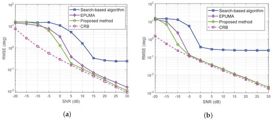
Figure 3.
RMSE of three methods versus SNR with ten off-grid sources in the case of different numbers of snapshots: (a) 20 snapshots. (b) 500 snapshots.
To examine the estimation accuracy with different snapshots cases, the RMSE of the proposed method versus number of snapshots with different SNR values is shown in Figure 4. The snapshots number varies from 10 to 10,000. Consider four off-grid sources arriving from and ten off-grid sources arriving from . The Monte-Carlo trials is 200. Obviously, the RMSE values decrease with the increase of the snapshots number. Moreover, the RMSE of the proposed algorithm can achieve the CRB when the SNR is larger than a threshold value even with few snapshots.
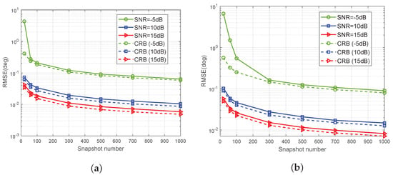
Figure 4.
RMSE of the proposed method versus snapshot number with different SNR values: (a) four off-grid sources. (b) ten off-grid sources.
To investigate the resolution of the proposed method, the RMSE of the above three algorithms versus SNR with two closely-spaced off-grid sources arriving from are plotted in Figure 5. We run 200 Monte-Carlo simulations to calculate each value of the RMSE. The CRB is plotted for benchmark. From the respective of spatial resolution, the proposed algorithm is superior to the search-based algorithm and EPUMA. In addition, the RMSE of the search-based algorithm always has a certain distance from the CRB, whereas the RMSE of the proposed method coincides with the CRB gradually. The EPUMA is inferior to the proposed method in terms of estimation accuracy especially in the low SNR case.
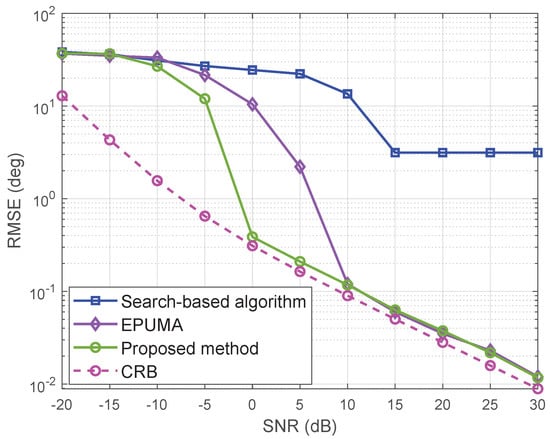
Figure 5.
RMSE of three methods versus SNR with two closely-spaced off-grid sources.
To examine the estimation performance in the case of two sources arriving from with different powers, the RMSE of the search-based algorithm, EPUMA and the proposed method versus SNR are presented in Figure 6. The power ratio of the first source to the second source is . The SNR is defined as the ratio of the first source to the noise power. 200 Monte-Carlo runs are utilized for calculation. The CRB curves are also plotted for comparision. The search-based algorithm and EPUMA exhibit much lower estimation accuracy than the proposed method. The RMSE of the proposed method approaches the CRB when SNR is larger than 5dB.
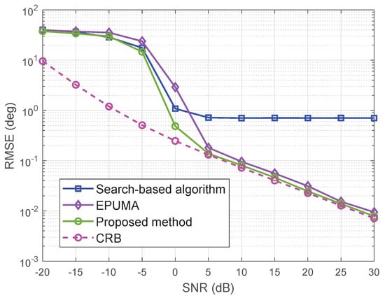
Figure 6.
RMSE of proposed method versus SNR in the case of two sources with different powers.
To examine the variation of the estimation performance with the number of sources, the RMSE of the proposed method versus source number in the case of different SNR values are provided in Figure 7. We run 200 Monte-Carlo simulations to calculate the RMSE. Observe that the RMSE increases as the source number increases. Moreover, the proposed algorithm exhibits low estimation accuracy even if the source number is larger than the antenna number.
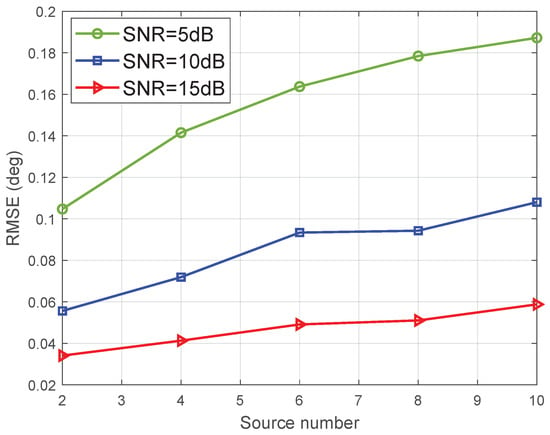
Figure 7.
RMSE of proposed method versus source number in the case of different SNR values.
To further investigate the effect of the antenna number on the estimation performance, we randomly select 8, 10, 15 out of 20 uniformly spaced antennas to construct nonuniform linear arrays (NLAs), which are given by array (a), array (b), array (c) respectively in Figure 8. Obviously, three NLAs consisting of a different number of antennas can form the same aperture length. The RMSE of the proposed method versus SNR for the three NLAs are given in Figure 9. Consider four off-grid sources arriving from . 200 Monte-Carlo trials are utilized to obtain each point. The CRB are also provided. It can be observe that the RMSE of the proposed method achieves the CRB when SNR is larger than a threshold. Moreover, the RMSE decreases as the antenna number increases with fixed SNR.
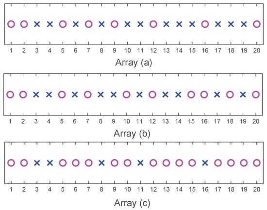
Figure 8.
The NLAs: (a) the selected 8-antenna NLA; (b) the selected 10-antenna NLA; (c) the selected 15-antenna NLA. Circles indicate selected antenna positions, while crosses discarded.
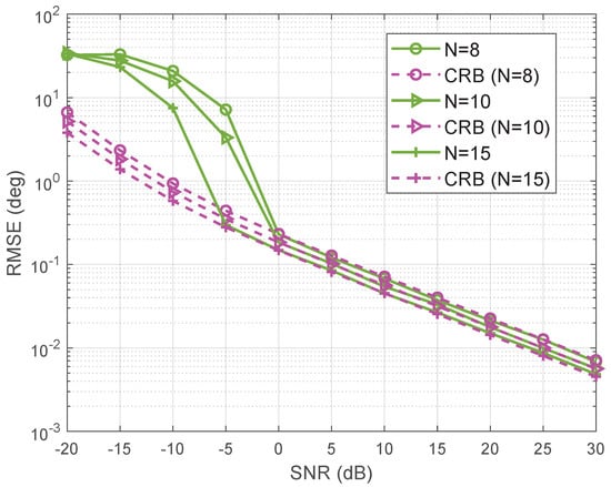
Figure 9.
RMSE of proposed method versus SNR in the case of different antenna numbers for NLA.
We compare the computational complexity of search-based algorithm, EPUMA and the proposed method in Table 1. The phases of K sources are corrected by searching phase offsets in the search-based algorithm and the grid point number D for search process is comparatively large. The computational complexity of EPUMA is with G being the subsets of DOA candidates and H being iteration number. If the element number of the difference coarray is much larger than the source number K, the complexity becomes and the subsets number G is relatively large. Moreover, multiple snapshots case also increases the computational complexity of EPUMA. The complexity of signal power correction based on the closed-form formula derived in the proposed method is because of the calculation of the inverse matrix with dimension . Meanwhile, the complexity of angle correction based on the simple interpolation method proposed in this paper is with H being iteration number and H is small for the convergence of the proposed algorithm. We can observe from the table that the complexity of the proposed method is smaller than that of the search-based algorithm and EPUMA.

Table 1.
Computational complexity of three methods.
The carrier frequencies of four signals are MHz, respectively. The sampling frequency is set as 2 MHz and the bandwidth of each signal is MHz. The snapshots number is 500. The spectra of four candidate emitted signals are graphically illustrated in Figure 10.
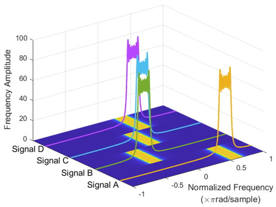
Figure 10.
Spectrums of four candidate emitted signals.
To investigate the performance of the frequency spectrum recovery, we consider the carrier frequencies of four signals as in Figure 10. The frequency spectra of four sources acquired from the proposed algorithm with the SNR being 10 dB is shown in Figure 11. The number of snapshot utilized for data processing is 20. It can be observed that the frequency spectra of the four signals can be accurately recovered with few snapshots.
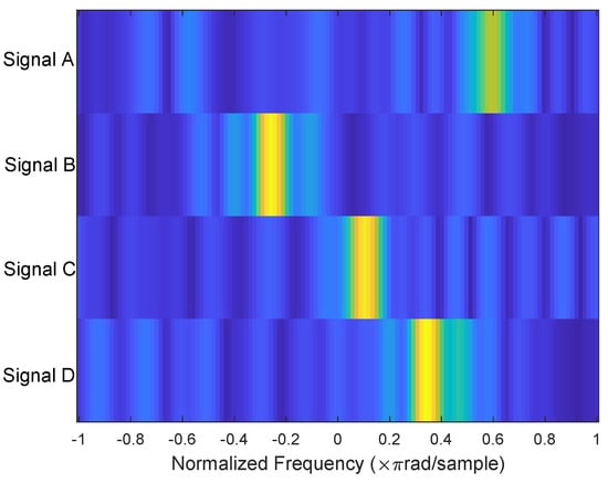
Figure 11.
Frequency spectra of four sources recovered by the proposed algorithm.
To further examine the performance of the angle and frequency spectrum recovery, we consider the angles and carrier frequencies of different numbers of signals. The angles and carrier frequencies of two signals are and MHz, respectively. The angles and carrier frequencies of four signals as in Figure 2 and Figure 10 respectively. The angles and carrier frequencies of six signals are and MHz, respectively. The space-frequency spectra acquired from the proposed method with the SNR being 10 dB is displayed in Figure 12. The number of snapshot is also set as 20. It is apparent that signals in all considered scenarios can be clearly distinguished. Meanwhile, the proposed algorithm exhibits high angle and frequency spectrum estimation accuracy.

Figure 12.
Space-frequency spectra recovered by the proposed algorithm in the case of different sources: (a) two off-grid sources. (b) four off-grid sources. (c) six off-grid sources.
5. Conclusions
An effective angle and frequency spectrum estimation algorithm using difference coarray was proposed in this paper. A simple interpolation method was developed to correct the DOA estimate of each source iteratively. The frequency spectrum was obtained by estimating the frequency response matrix. Moreover, the disadvantages that DOA estimation based on difference coarray requires a large number of snapshots was overcome by introducing the deterministically orthogonal signals whose source covariance matrix is diagonal. Simulation results indicated that the proposed method was superior to the search-based algorithm and EPUMA from the point view of the estimation accuracy. Specifically, the RMSE of the proposed algorithm was 0.27 degrees lower than that of the EPUMA and 0.012 degrees lower than that of the search-based algorithm respectively in the case of more sources than antenna elements with 20 snapshots. In the case of few snapshots, the RMSE was able to coincide with the CRB when the SNR is larger than 0 dB and 5 dB with four and ten off-grid sources respectively. In addition, the frequency spectrum was recovered accurately based on the previous accurate DOA estimates, which demonstrated the efficiency of the proposed algorithm for angle and frequency spectrum estimation with few snapshots using difference coarray.
Author Contributions
Conceptualization, D.L., Y.M. and Y.F.; methodology, D.L. and Y.M.; software simulation and parameter optimization, D.L. and Y.M.; validation, G.F.; writing—original draft preparation, D.L. and Y.M.; writing—review and editing, G.F.; supervision, Y.F. All authors have read and agreed to the published version of the manuscript.
Funding
This research was supported by the National Natural Science Foundation of China, grant number 61801503.
Informed Consent Statement
Not applicable.
Data Availability Statement
The matlab code is available from the corresponding author.
Conflicts of Interest
The authors declare no conflict of interest.
References
- Krim, H.; Viberg, M. Two decades of array signal processing research: The parametric approach. IEEE Signal Process. Mag. 1996, 13, 67–94. [Google Scholar] [CrossRef]
- Heidenreich, P.; Zoubir, M.A. Fast maximum likelihood DOA estimation in the two-target case with applications to automotive radar. Signal Process. 2013, 93, 3400–3409. [Google Scholar] [CrossRef]
- Wang, X.R.; Zhai, W.T.; Greco, M.; Gini, F. Cognitive sparse beamformer design in dynamic environment via regularized switching network. IEEE Trans. Aerosp. Electron. Syst. 2022, 1–17. [Google Scholar] [CrossRef]
- Zhai, W.T.; Wang, X.R.; Cao, X.B.; Greco, S.M.; Gini, F. Reinforcement learning based dual-functional massive MIMO systems for multi-target detection and communications. IEEE Trans. Signal Process. 2023, 71, 741–755. [Google Scholar] [CrossRef]
- Li, D.; Wang, J.; Fu, Y.W. A joint angle and spectrum estimation algorithm for uniform linear array. IEEE Sens. J. 2022, 22, 16244–16253. [Google Scholar] [CrossRef]
- Wang, X.R.; Li, W.L.; Chen, C.V. Hand gesture recognition using radial and transversal dual micromotion features. IEEE Trans. Aerosp. Electron. Syst. 2022, 58, 5963–5973. [Google Scholar] [CrossRef]
- Zhang, X.; Wang, X.R.; So, C.H.; Zoubir, M.A.; Cui, G.L. Min-max optimization for MIMO radar waveform design with improved power efficiency. IEEE Trans. Signal Process. 2022, 70, 6112–6127. [Google Scholar] [CrossRef]
- Gurbuz, Z.S.; Griffiths, D.H.; Charlish, A.; Rangaswamy, M.; Greco, S.M.; Bell, K. An overview of cognitive radar: Past, present, and future. IEEE Aerosp. Electron. Syst. Mag. 2019, 34, 6–18. [Google Scholar] [CrossRef]
- Pal, P.; Vaidyanathan, P.P. Nested arrays: A novel approach to array processing with enhanced degrees of freedom. IEEE Trans. Signal Process. 2010, 58, 4167–4181. [Google Scholar] [CrossRef]
- Vaidyanathan, P.P.; Pal, P. Sparse sensing with co-prime samplers and arrays. IEEE Trans. Signal Process. 2011, 59, 573–586. [Google Scholar] [CrossRef]
- Pal, P.; Vaidyanathan, P.P. A grid-less approach to underdetermined direction of arrival estimation via low rank matrix denoising. IEEE Signal Process. Lett. 2014, 21, 737–741. [Google Scholar] [CrossRef]
- Zhou, C.; Gu, Y.; Fan, X.; Shi, Z.; Mao, G.; Zhang, D.Y. Direction-of-arrival estimation for coprime array via virtual array interpolation. IEEE Trans. Signal Process. 2018, 66, 5956–5971. [Google Scholar] [CrossRef]
- Wang, M.; Zhang, Z.; Nehorai, A. Direction finding using sparse linear arrays with missing data. In Proceedings of the 2017 IEEE International Conference on Acoustics, Speech and Signal Processing (ICASSP), New Orleans, LA, USA, 5–9 March 2017; pp. 3066–3070. [Google Scholar]
- Wang, M.; Zhang, Z.; Nehorai, A. Grid-less DOA estimation using sparse linear arrays based on wasserstein distance. IEEE Signal Process. Lett. 2019, 26, 838–842. [Google Scholar] [CrossRef]
- Yuan, J.W.; Zhang, G.; Leung, H.; Ma, S.D. Off-grid DOA estimation for noncircular signals via block sparse representation using extended transformed nested array. IEEE Signal Process. Lett. 2023, 30, 130–134. [Google Scholar] [CrossRef]
- Cao, R.Z.; Liu, B.Y.; Gao, F.F.; Zhang, X.F. A low-complex one-snapshot DOA estimation algorithm with massive ULA. IEEE Commun. Lett. 2017, 21, 1071–1074. [Google Scholar] [CrossRef]
- Qian, C.; Huang, L.; Sidiropoulos, D.N.; So, C.H. Enhanced PUMA for direction-of-arrival estimation and its performance analysis. IEEE Trans. Signal Process. 2016, 64, 4127–4137. [Google Scholar] [CrossRef]
- Wang, X.R.; Aboutanios, E.; Amin, G.M. Adaptive array thinning for enhanced DOA estimation. IEEE Signal Process. Lett. 2015, 22, 799–803. [Google Scholar] [CrossRef]
- Amin, G.M.; Wang, X.R.; Zhang, D.Y.; Ahmad, F.; Aboutanios, E. Sparse arrays and sampling for interference mitigation and DOA estimation in GNSS. Proc. IEEE 2016, 104, 1302–1317. [Google Scholar] [CrossRef]
- Wang, X.R.; Amin, G.M.; Ahmad, F.; Aboutanios, E. Interference DOA estimation and suppression for GNSS receivers using fully augmentable arrays. IET Radar Sonar Navig. 2017, 11, 474–480. [Google Scholar] [CrossRef]
- Ma, Y.N.; Cao, X.B.; Wang, X.R. Off-grid DOA estimation with arbitrary-spaced linear array using single snapshot. In Proceedings of the 2019 IEEE Radar Conference (RadarConf), Boston, MA, USA, 22–26 April 2019; pp. 1–6. [Google Scholar]
- Ma, Y.N.; Cao, X.B.; Wang, X.R.; Greco, S.M.; Gini, F. Multi-source off-grid DOA estimation with single snapshot using non-uniform linear arrays. Signal Process. 2021, 189, 108238. [Google Scholar] [CrossRef]
- Chen, P.; Chen, Z.; Zhang, X.; Liu, L. SBL-based direction finding method with imperfect array. Electronics 2018, 7, 426. [Google Scholar] [CrossRef]
- Ling, Y.; Gao, H.; Ru, G.; Chen, H.; Li, B.; Cao, T. Grid reconfiguration method for off-grid DOA estimation. Electronics 2019, 8, 1209. [Google Scholar] [CrossRef]
- Lemma, N.A.; van der Veen, J.A.; Deprettere, F.E. Analysis of joint angle-frequency estimation using ESPRIT. IEEE Trans. Signal Process. 2003, 51, 1264–1283. [Google Scholar] [CrossRef]
- Qian, C.; Huang, L.; Shi, Y.; So, C.H. Joint angle and frequency estimation using structured least squares. In Proceedings of the 2014 IEEE International Conference on Acoustics, Speech and Signal Processing (ICASSP), Florence, Italy, 4–9 May 2014; pp. 2972–2976. [Google Scholar]
- Liu, F.; Zhang, Z.; Du, R.; Sheng, J.; Huang, C. Frequency-angle spectrum hole detection with Taylor expansion based focusing transformation. IEEE Trans. Mobile Comput. 2020, 19, 2330–2343. [Google Scholar] [CrossRef]
- Xu, L.; Wen, F.; Zhang, X. A novel unitary PARAFAC algorithm for joint DOA and frequency estimation. IEEE Commun. Lett. 2019, 23, 660–663. [Google Scholar] [CrossRef]
- Ioushua, S.S.; Yair, O.; Cohen, D.; Eldar, C.Y. CaSCADE: Compressed carrier and DOA estimation. IEEE Trans. Signal Process. 2017, 65, 2645–2658. [Google Scholar] [CrossRef]
- Lv, W.; Wang, H.; Mu, S.; Luo, Z. Performance bounds of joint angle-frequency estimation based on spatio-temporal co-prime sampling. IET Radar Sonar Navig. 2018, 12, 565–574. [Google Scholar] [CrossRef]
- Huang, X.; Zhao, X.; Ma, J. Joint carrier and DOA estimation for multi-band sources based on sub-Nyquist sampling coprime array with large time lags. Signal Process. 2022, 195, 108466. [Google Scholar] [CrossRef]
- Liu, L.; Gu, F.J.; Wei, P.; Luo, Z. Joint DOA and frequency estimation with sub-Nyquist sampling. Signal Process. 2019, 154, 87–96. [Google Scholar] [CrossRef]
- Liu, L.; Wei, P. Joint DOA and frequency estimation with sub-Nyquist sampling in the sparse array system. IEEE Signal Process. Lett. 2018, 25, 1285–1289. [Google Scholar] [CrossRef]
- Aubry, A.; Maio, D.A.; Govoni, A.M. Two-dimensional spectrum sensing for cognitive radar. In Proceedings of the 2018 IEEE Radar Conference (RadarConf18), Oklahoma City, OK, USA, 23–27 April 2018; pp. 815–820. [Google Scholar]
- Aubry, A.; Maio, D.A.; Carotenuto, V.; Govoni, A.M. Multi-snapshot spectrum sensing for cognitive radar via block sparsity exploitation. IEEE Trans. Signal Process. 2019, 67, 1396–1406. [Google Scholar] [CrossRef]
- Yang, L.L.; Li, J.; Chen, F.J.; Zheng, Z.; Ji, F.; Yu, H. Joint angular-frequency distribution estimation via spatial-temporal sparse sampling and low-rank matrix recovery. Signal Process. 2023, 206, 108918. [Google Scholar] [CrossRef]
- Wang, X.H.; Tan, P.C.; Wu, F.; Wang, J.D. Fault-tolerant attitude control for rigid spacecraft without angular velocity measurements. IEEE Trans. Cybern. 2019, 51, 1216–1229. [Google Scholar] [CrossRef] [PubMed]
- Ma, Y.N.; Cao, X.B.; Wang, X.R. Enhanced off-grid DOA estimation by corrected power Bayesian inference using difference coarray. J. Eng. 2019, 21, 7989–7993. [Google Scholar] [CrossRef]
- Ma, Y.N.; Cao, X.B.; Wang, X.R. Multi-source off-grid DOA estimation using iterative phase offset correction in coarray domain. Digit. Signal Process. 2021, 112, 102998. [Google Scholar] [CrossRef]
- Ottersten, B.; Stoica, P.; Roy, R. Covariance matching estimation techniques for array signal processing applications. Digit. Signal Process. 1998, 8, 185–210. [Google Scholar] [CrossRef]
- Li, J.; Zheng, D.; Stoica, P. Angle and waveform estimation via RELAX. IEEE Trans. Aerosp. Electron. Syst. 1997, 33, 1077–1087. [Google Scholar] [CrossRef]
- Sedighi, S.; Rao, R.M.S.B.; Ottersten, B. An asymptotically efficient weighted least squares estimator for co-array-based DOA estimation. IEEE Trans. Signal Process. 2020, 68, 589–604. [Google Scholar] [CrossRef]
Disclaimer/Publisher’s Note: The statements, opinions and data contained in all publications are solely those of the individual author(s) and contributor(s) and not of MDPI and/or the editor(s). MDPI and/or the editor(s) disclaim responsibility for any injury to people or property resulting from any ideas, methods, instructions or products referred to in the content. |
© 2023 by the authors. Licensee MDPI, Basel, Switzerland. This article is an open access article distributed under the terms and conditions of the Creative Commons Attribution (CC BY) license (https://creativecommons.org/licenses/by/4.0/).