


Improve Model Testing by Integrating Bounded Model Checking and Coverage Guided Fuzzing


Abstract
1. Introduction
- (1)
- We developed SPsCGF, an integration method which integrates the bounded model-checking method and coverage guided fuzzing method together to generate test cases for models with signal inputs. In coverage guided fuzzing modules, SPsCGF takes signal patterns into consideration to improve the mutation operators of fuzzing methods. We have implemented SPsCGF as a standalone application. The SPsCGF relies on the existing state-of-the-art model checking tool CBMC [20] as well as AFL [21], a state-of-the-art, open-source coverage guided fuzzing framework.
- (2)
- We compared SPsCGF with two state-of-the-art baselines to assess the effectiveness and efficiency of the proposed testing method. Our experiments, performed on 12 publicly available Simulink models from the commonly used benchmarks and industry cases, show that, on average, SPsCGF achieves 8% to 38% more coverage and performs 3× to 10× faster than state-of-art baselines.
- (3)
- We evaluated the usefulness of SPsCGF in real large industrial CPS models from the vehicle control domain. Those models are real industry models from our industrial partner. Those models have different formats and run under different environments. SPsCGF successfully tests those models and achieves high coverage.
2. Model Testing with Time Series Data Input
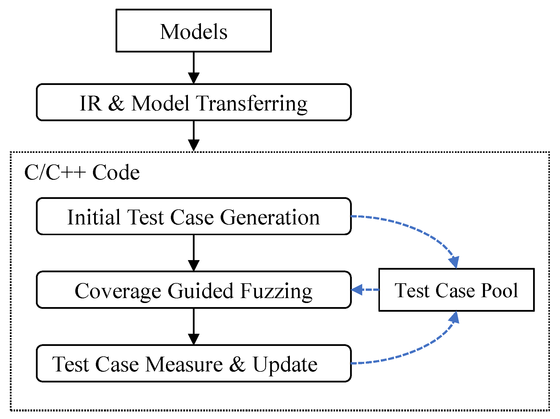
3. Overall Framework
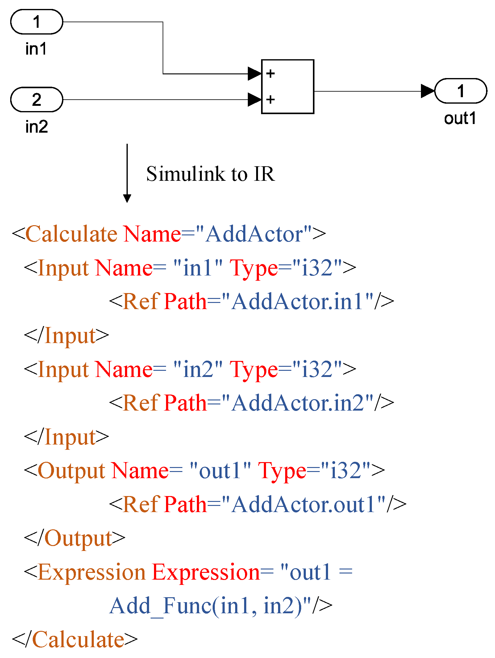
3.1. IR and Model Transferring
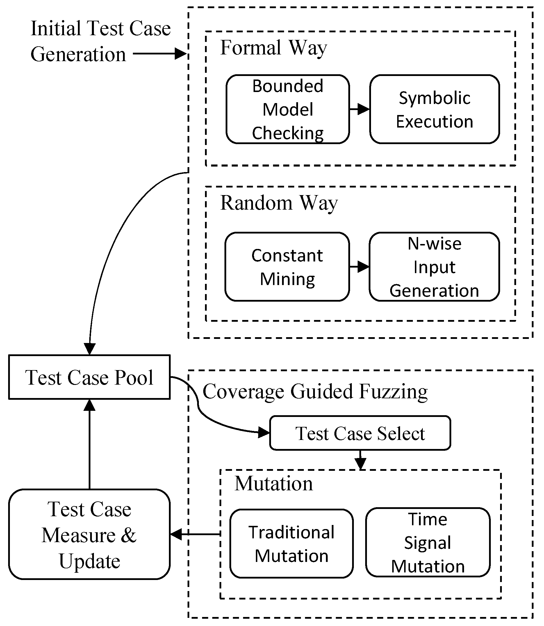
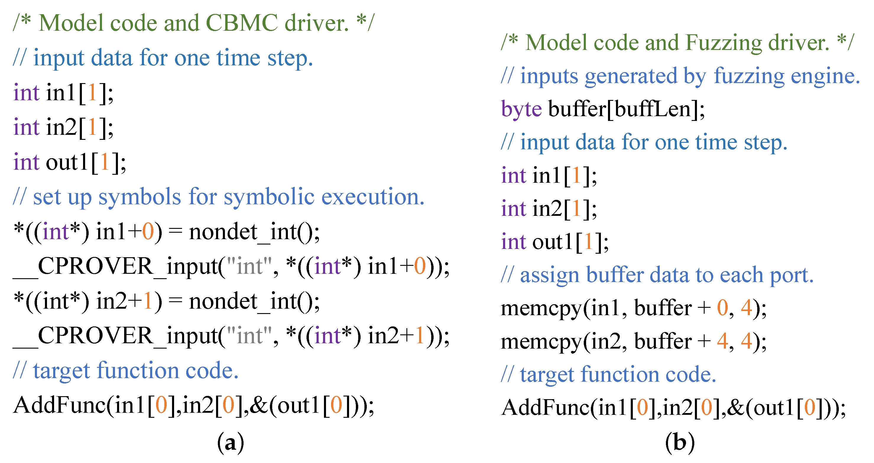
3.2. Initial Test Case Generation
| Algorithm 1 FastNWise(n, portIndex) |
Require: two parameters; 1: n is the desired n-wise; 2: portIndex is the relative index of all constant ports; Ensure: the test cases which satisfy n-wise; 3: S = all constant values of port at portIndex; 4: a = randomly select an element in S; 5: R = S - a; 6: = {a} × FastNWise(n, portIndex-1); 7: = R × FastNWise(n-1, portIndex-1); 8: =∪; 9: return ; |
3.3. Coverage Guided Fuzzing
3.3.1. Seed Selection
| Algorithm 2 SeedSelect(pool) |
Require: one parameter; 1: pool is the test case pool; Ensure: one suitable test case; 2: distribute = []; 3: for each case ∈ pool do 4: prob = ; 5: prob2 = 0; 6: counter = 0; 7: for ∈ half flipped conditions do 8: prob2 += ; 9: counter++; 10: end for 11: case_prob = prob * (prob2 / counter); 12: distribute.append(case_prob); 13: end for 14: = Sample(distribute); 15: return test case in pool; |
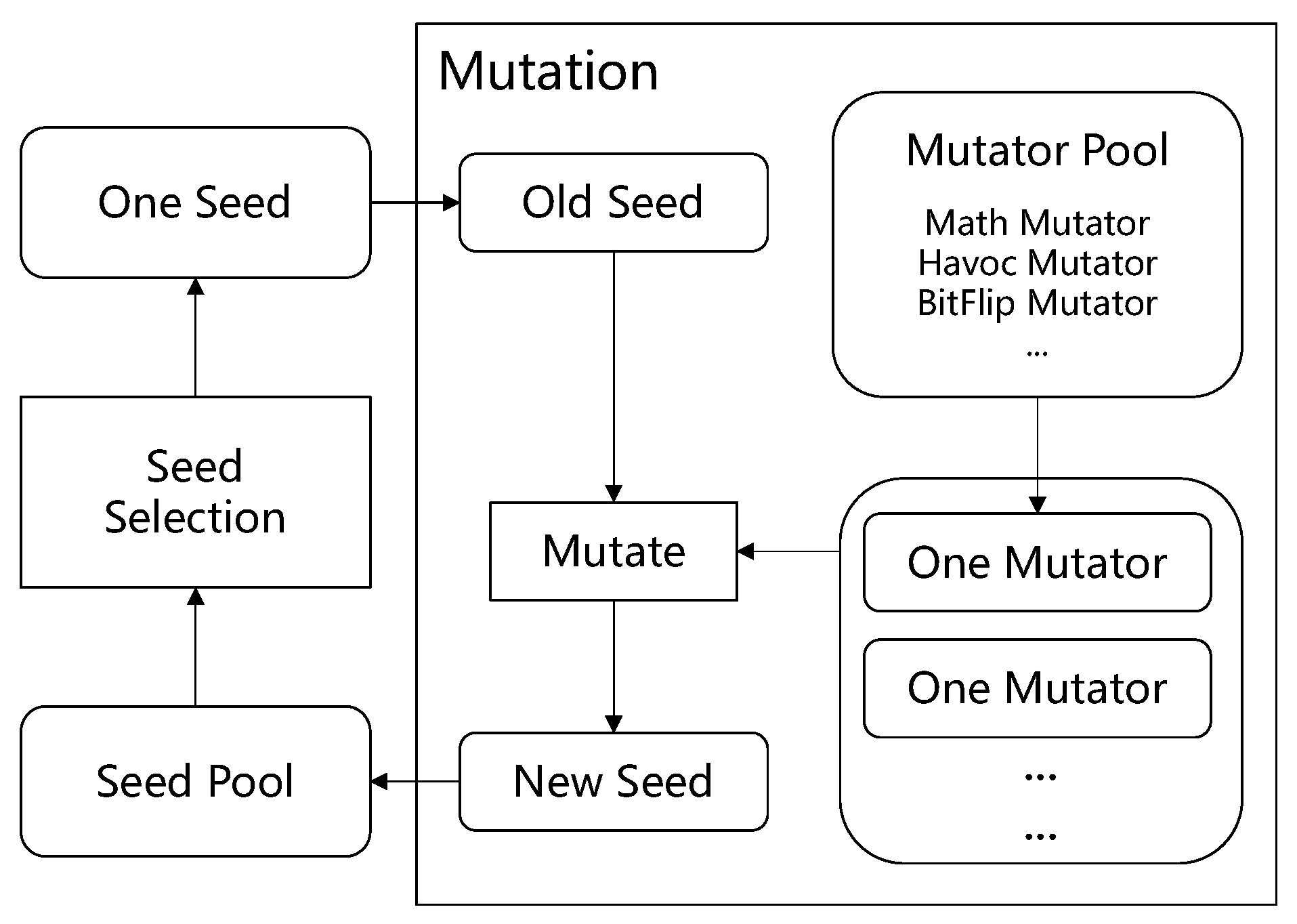
3.3.2. Mutation
- (1)
- RandomSet Mutator. This randomly chooses a number of positions and changes the values on those positions to another random values. The random values can be the mined constant values mentioned in previous subsections. The value ranges of ports are taken into consideration. When generating random values for those ports, if some positions in test input have the constraint of value ranges, we will randomly set values according to ranges. For example, for a model with 4 ports, each port takes an integer as input, these 4 integers are filled into a byte array names as , the first 4 bytes in which represents the integer value for 0th port can be randomly set to a random value in [0,10] if the value range of 0th port is [0,10].
- (2)
- BitFlip Mutator. This flips a seed by bits. The smallest unit to bit flip is a byte. We flip n bytes each time and n is a random number. For example, if we flip a byte in a seed, this changes the original seed byte from 01110001 to 10001110. The non-deterministic mutation randomly selects bytes for flipping.The deterministic mutation flips all bytes in a seed. We combine deterministic mutations and non-deterministic mutations together.
- (3)
- Math Mutator. This randomly selects a number of positions in a seed to do mathematical operations. The operations contain commonly used math operations such as add, subtract, multiply, and divide. The operands are selected from 1 to a specified MAX value. For example, if a seed is a byte array of length 4, if the math is applied to the byte of , then += 14. The value 14 is also randomly chosen for mutation.
- +
- +1, +2, +3, +4 …, + MAX
- −
- MAX
- *
- *2, *3, *4, …, *MAX
- /
- /2, /3, /4, …, /MAX
- (4)
- Havoc Mutator. This is for destroying a seed as much as possible. The destruction includes setting some data in a seed to specific extreme values such as and 127 for a char type value, and 32,767 for a short type value and so on. If the data type of a seed cannot be determined, some consecutive bytes of the seed are randomly selected, and all bits in them are assigned 1 or 0. The destruction also includes swapping parts of a single seed and crossing over two seeds. To cross over two seeds, we divide each seed into the same two parts, and then randomly splice these divided parts. For example, if seed a is [1,5,6], seed b is [127,,6,3], the a is split into [1,5] and [6], the b is split into [127,] and [6,3], the cross over result can be [1,5,6,3] and [127,].
- (1)
- Square Signal Mutator. The square signal does not strictly force the signal to be the shape of a square. Instead, this mutator randomly chooses a continuous piece of data in test input and makes all the chosen data to the same value. This is applied when the inputs of some ports are time series data. For example, if the original seed is [1,5,127,], then, the mutated seed can be [1,10,10,], the middle piece of data is set to a fixed random value.
- (2)
- Curve Signal Mutator. The curve signal randomly chooses a continuous piece of data and sets the data to the randomly generated continuous curve. The curve generating algorithm is as follows: . The generated curve will be randomly truncated to be the same length as the data chosen for mutation. For example, if the original seed is [1,5,127,], then, the mutated seed can be [1,sin(0.1),sin(0.2),], the middle piece of data is set to a piece of a curve signal wave .
3.4. Test Case Measure and Update
| Algorithm 3 record(res, cond_index, dec_index) |
Require: two parameters; 1: res is the boolean result of expression e; 2: cond_index is the condition index of expression e; 3: dec_index is the decision index of the expression containing expression e; Ensure: record the result: res; 4: ; 5: return ; |
4. Evaluation
- Effectiveness—RQ1: Can this proposed method improve the coverage compared to baselines? How much coverage can this proposed method improve?
- Efficiency—RQ2: Can this method improve the running speed compared to baselines? How much faster can this method run?
- Usefulness—RQ3: In the actual large-scale model, do the newly proposed mutation operators based on signal patterns have any effect? Can the fuzzing module improve MC/DC coverage?
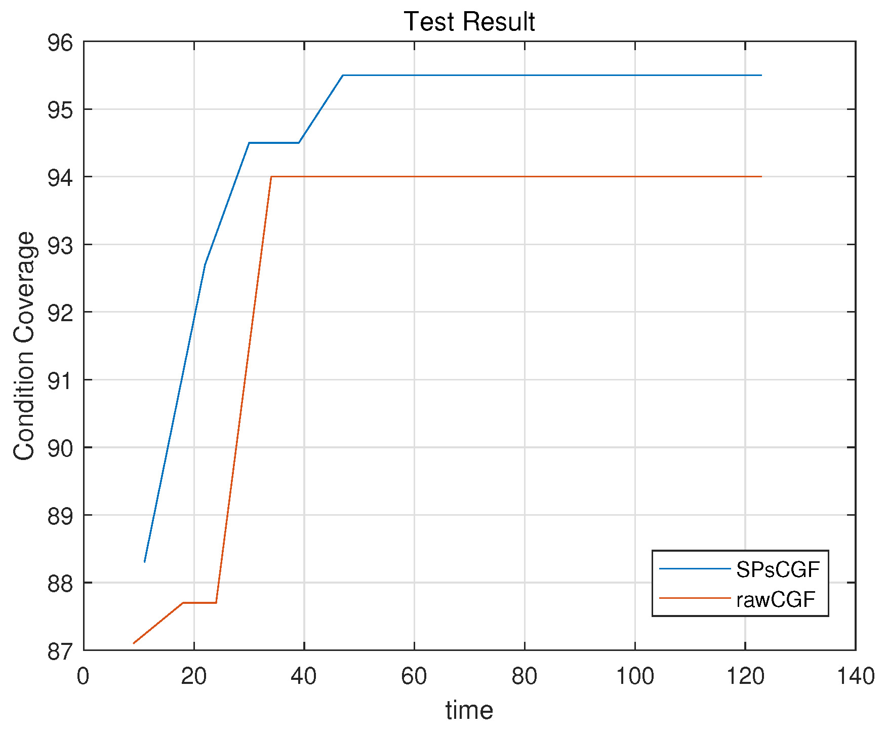
4.1. RQ1—Effectiveness
4.2. RQ2—Efficiency
4.3. RQ3—Usefulness
5. Related Work
6. Limitation and Future Work
7. Conclusions
Funding
Institutional Review Board Statement
Informed Consent Statement
Data Availability Statement
Conflicts of Interest
References
- MathWorks. MATLAB Simulink. 2022. Available online: https://www.mathworks.com/products/simulink.html (accessed on 10 February 2023).
- Antonya, C.; Boboc, R.G. Computational efficiency of multi-body systems dynamic models. Robotica 2021, 39, 2333–2348. [Google Scholar] [CrossRef]
- Mourtzis, D.; Angelopoulos, J.; Panopoulos, N. Manufacturing personnel task allocation taking into consideration skills and remote guidance based on augmented reality and intelligent decision making. Int. J. Comput. Integr. Manuf. 2023, 36, 70–85. [Google Scholar] [CrossRef]
- MathWorks. MATLAB Simulink Stateflow. 2022. Available online: https://www.mathworks.com/products/stateflow.html (accessed on 10 February 2023).
- Khurshid, S.; Pasareanu, C.; Visser, W. Generalized Symbolic Execution for Model Checking and Testing; Springer: Berlin/Heidelberg, Germany, 2003. [Google Scholar]
- Pretschner, A.; Slotosch, O.; Aiglstorfer, E.; Kriebel, S. Model-based testing for real: The inhouse card case study. Int. J. Softw. Tools Technol. Transf. 2004, 5, 140–157. [Google Scholar] [CrossRef]
- Gadkari, A.A.; Yeolekar, A.; Suresh, J.; Ramesh, S.; Mohalik, S.; Shashidhar, K.C. AutoMOTGen: Automatic Model Oriented Test Generator for Embedded Control Systems. In Computer Aided Verification: Proceedings of the 20th International Conference, Princeton, NJ, USA, 7–14 July 2008; Gupta, A., Malik, S., Eds.; Lecture Notes in Computer Science; Springer: Berlin/Heidelberg, Germany, 2008; Volume 5123, pp. 204–208. [Google Scholar] [CrossRef]
- Mazzolini, M.; Brusaferri, A.; Carpanzano, E. Model-Checking based Verification approach for advanced Industrial Automation solutions. In Proceedings of the 15th IEEE International Conference on Emerging Technologies and Factory Automation, Bilbao, Spain, 13–16 September 2010; pp. 1–8. [Google Scholar] [CrossRef]
- Barnat, J.; Brim, L.; Beran, J.; Kratochvila, T.; Oliveira, I.R. Executing Model Checking Counterexamples in Simulink. In Proceedings of the Sixth International Symposium on Theoretical Aspects of Software Engineering, Beijing, China, 4–6 July 2012; pp. 245–248. [Google Scholar] [CrossRef]
- MathWorks. Simulink Design Verifier. 2022. Available online: https://www.mathworks.com/products/simulink-design-verifier.html (accessed on 10 February 2023).
- Meng, L.; Kumar, R. Model-based automatic test generation for Simulink/Stateflow using extended finite automaton. In Proceedings of the IEEE International Conference on Automation Science & Engineering, Seoul, Republic of Korea, 20–24 August 2012. [Google Scholar]
- Baresel, A.; Pohlheim, H.; Sadeghipour, S. Structural and Functional Sequence Test of Dynamic and State-Based Software with Evolutionary Algorithms. In Genetic and Evolutionary Computation Conference, Proceedings of the Genetic and Evolutionary Computation Conference (GECCO 2003), Chicago, IL, USA, 12–16 July 2003; Lecture Notes in Computer Science; Springer: Berlin/Heidelberg, Germany, 2003; pp. 2428–2441. [Google Scholar]
- Windisch, A.; Lindlar, F.F.; Topuz, S.; Wappler, S. Evolutionary functional testing of continuous control systems. In Proceedings of the Genetic and Evolutionary Computation Conference, Montreal, QC, Canada, 8–12 July 2009; pp. 1943–1944. [Google Scholar] [CrossRef]
- Lindlar, F.F.; Windisch, A.; Wegener, J. Integrating Model-Based Testing with Evolutionary Functional Testing. In Proceedings of the Third International Conference on Software Testing, Verification and Validation, ICST 2010, Paris, France, 7–9 April 2010; pp. 163–172. [Google Scholar] [CrossRef]
- Wilmes, B.; Windisch, A. Considering Signal Constraints in Search-Based Testing of Continuous Systems. In Proceedings of the Third International Conference on Software Testing, Verification and Validation, ICST 2010, Paris, France, 7–9 April 2010; pp. 202–211. [Google Scholar] [CrossRef]
- Zander-nowicka, J. Model-Based Testing of Real-Time Embedded Systems in the Automotive Domain. Ph.D. Thesis, Faculty IV—Electrical Engineering and Computer Science Technical University Berlin, Berlin, Germany, 2014. [Google Scholar]
- Reactive Systems. Reactis Tester. 2011. Available online: https://reactive-systems.com/news.msp?nid=83 (accessed on 10 February 2023).
- Satpathy, M.; Yeolekar, A.; Peranandam, P.M.; Ramesh, S. Efficient coverage of parallel and hierarchical stateflow models for test case generation. Softw. Test. Verification Reliab. 2012, 22, 457–479. [Google Scholar] [CrossRef]
- Böhr, F.; Eschbach, R. SIMOTEST: A tool for automated testing of hybrid real-time Simulink models. In Proceedings of the IEEE 16th Conference on Emerging Technologies & Factory Automation, ETFA 2011, Toulouse, France, 5–9 September 2011; pp. 1–4. [Google Scholar] [CrossRef]
- Clarke, E.; Kroening, D.; Lerda, F. A Tool for Checking ANSI-C Programs. In Tools and Algorithms for the Construction and Analysis of Systems, Proceedings of the 10th International Conference, TACAS 2004, Held as Part of the Joint European Conferences on Theory and Practice of Software, ETAPS 2004, Barcelona, Spain, 29 March–2 April 2004; Jensen, K., Podelski, A., Eds.; Lecture Notes in Computer Science; Springer: Berlin/Heidelberg, Germany, 2004; Volume 2988, pp. 168–176. [Google Scholar]
- Fioraldi, A.; Maier, D.; Eißfeldt, H.; Heuse, M. AFL++: Combining Incremental Steps of Fuzzing Research. In Proceedings of the 14th USENIX Workshop on Offensive Technologies (WOOT 20), Berkeley, CA, USA, 11 August 2020. [Google Scholar]
- Matinnejad, R.; Nejati, S.; Briand, L.C.; Bruckmann, T. Automated test suite generation for time-continuous simulink models. In Proceedings of the IEEE/ACM International Conference on Software Engineering, Austin, TX, USA, 14–22 May 2016. [Google Scholar]
- Dang, T.; Donzé, A.; Maler, O. Verification of Analog and Mixed-Signal Circuits Using Hybrid System Techniques. In Proceedings of the Formal Methods in Computer-aided Design, International Conference, Fmcad, Austin, TX, USA, 15–17 November 2004. [Google Scholar]
- Fehnker, A.; Ivancic, F. Benchmarks for Hybrid Systems Verification. In Proceedings of the Hybrid Systems: Computation and Control, International Workshop, Hscc, Philadelphia, PA, USA, 25–27 March 2004. [Google Scholar]
- Roohi, N.; Wang, Y.; West, M.; Dullerud, G.E.; Viswanathan, M. Statistical Verification of the Toyota Powertrain Control Verification Benchmark. In Proceedings of the 20th International Conference on Hybrid Systems: Computation and Control, Pittsburgh, PA, USA, 18–20 April 2017. [Google Scholar]
- Sankaranarayanan, S.; Fainekos, G. Simulating Insulin Infusion Pump Risks by In-Silico Modeling of the Insulin-Glucose Regulatory System. In Proceedings of the 10th International Conference on Computational Methods in Systems Biology, London, UK, 3–5 October 2012. [Google Scholar]
- Zhao, Q.; Krogh, B.H.; Hubbard, P. Generating test inputs for embedded control systems. IEEE Control. Syst. 2003, 23, 49–57. [Google Scholar]
- Nejati, S.; Gaaloul, K.; Menghi, C.; Briand, L.C.; Foster, S.; Wolfe, D. Evaluating model testing and model checking for finding requirements violations in Simulink models. In Proceedings of the 2019 27th ACM Joint Meeting on European Software Engineering Conference and Symposium on the Foundations of Software Engineering, Tallinn, Estonia, 26–30 August 2019; pp. 1015–1025. [Google Scholar]
- Hermanns, H.; Wachter, B.; Zhang, L. Probabilistic CEGAR. In Computer Aided Verification, Proceedings of the 20th International Conference, CAV 2008, Princeton, NJ, USA, 7–14 July 2008; Springer: Berlin/Heidelberg, Germany, 2008; pp. 162–175. [Google Scholar]
- Beyer, D.; Lwe, S. Explicit-State Software Model Checking Based on CEGAR and Interpolation. In Proceedings of the 16th International Conference on Fundamental Approaches to Software Engineering, Rome, Italy, 16–24 March 2013. [Google Scholar]
- Prabhakar, P.; Duggirala, P.S.; Mitra, S.; Viswanathan, M. Hybrid Automata-Based CEGAR for Rectangular Hybrid Systems. Form. Methods Syst. Des. 2015, 46, 105–134. [Google Scholar] [CrossRef]
- Beyer, D.; Löwe, S. Explicit-Value Analysis Based on CEGAR and Interpolation. arXiv 2012, arXiv:1212.6542. [Google Scholar]
- Matsunaga, Y. Accelerating SAT-based Boolean matching for heterogeneous FPGAs using one-hot encoding and CEGAR technique. IEICE Trans. Fundam. Electron. Commun. Comput. Sci. 2016, 99, 1374–1380. [Google Scholar] [CrossRef]
- Nellen, J.; Driessen, K.; Neuhäußer, M.; Ábrahám, E.; Wolters, B. Two CEGAR-based approaches for the safety verification of PLC-controlled plants. Inf. Syst. Front. 2016, 18, 927–952. [Google Scholar] [CrossRef]
- Satpathy, M.; Yeolekar, A.; Ramesh, S. Randomized directed testing (REDIRECT) for Simulink/Stateflow models. In Proceedings of the 8th ACM & IEEE International conference on Embedded software, EMSOFT 2008, Atlanta, GA, USA, 19–24 October 2008; pp. 217–226. [Google Scholar] [CrossRef]
- Tenório, M.; Lopes, R.; Fechine, J.; Marinho, T.; Costa, E. Subsumption in Mutation Testing: An Automated Model Based on Genetic Algorithm. In Conference Proceedings, Proceedings of the 16th International Conference on Information Technology-New Generations (ITNG 2019), Las Vegas, NV, USA, 1–3 April 2019; Latifi, S., Ed.; Advances in Intelligent Systems and Computing; Springer: Cham, Switzerland, 2019. [Google Scholar]
- Suzuki, T.; Furuhashi, T.; Matsushita, S.; Tsutsui, H. Efficient fuzzy modeling under multiple criteria by using genetic algorithm. IEEE Int. Conf. Syst. Man Cybern. 1999, 5, 314–319. [Google Scholar]
- Menghi, C.; Nejati, S.; Briand, L.; Parache, Y.I. Approximation-refinement testing of compute-intensive cyber-physical models: An approach based on system identification. In Proceedings of the 2020 IEEE/ACM 42nd International Conference on Software Engineering (ICSE), Seoul, Republic of Korea, 27 June–19 July 2020; pp. 372–384. [Google Scholar]
- Hanh, L.; Binh, N.T. Mutation Operators for Simulink Models. In Proceedings of the 2012 Fourth International Conference on Knowledge and Systems Engineering, Danang, Vietnam, 17–19 August 2012; pp. 54–59. [Google Scholar]
- Quyen, N.; Tung, K.T.; Le, T.; Binh, N.T. Improving Mutant Generation for Simulink Models using Genetic Algorithm. In Proceedings of the 2016 International Conference on Electronics, Information, and Communications (ICEIC), Danang, Vietnam, 27–30 January 2016. [Google Scholar]


| Condition & Decision Coverage | ||||
|---|---|---|---|---|
| Model | SPsCGF-BMC | SPsCGF | SLDV | SimCoTest |
| NLGuidance | 38% | 69% | 38% | 31% |
| RHB1 | 0% | 89% | 0% | 81% |
| RHB2 | 0% | 91% | 0% | 85% |
| Euler321 | 94% | 94% | 50% | 47% |
| BasicTwoTanks | 100% | 100% | 96% | 53% |
| EB | 98% | 98% | 93% | 0% |
| MHI1209 | 0% | 96% | 0% | 92% |
| AFC | 0% | 67% | 0% | 67% |
| AT | 0% | 79% | 0% | 68% |
| IGC | 0% | 100% | 0% | 96% |
| Regulator | 75% | 75% | 64% | 50% |
| BIMultiplexor | 88% | 88% | 88% | 69% |
| Time to Achieve Same Coverage | |||
|---|---|---|---|
| Model | SPsCGF | SLDV | SimCoTest |
| NLGuidance | 10 s | 171 s | 118 s |
| RHB1 | 5 s | NA | >180 s |
| RHB2 | 4 s | NA | >180 s |
| Euler321 | 2 s | 46 s | 152 s |
| BasicTwoTanks | 11s | >180 s | 143 s |
| EB | 15 s | 79 s | NA |
| MHI1209 | 27 s | NA | 127 s |
| AFC | 17 s | NA | >180 s |
| AT | 52 s | NA | >180 s |
| IGC | 7 s | NA | 120s |
| Regulator | 12 s | >180 s | 124 s |
| BIMultiplexor | 2 s | 12 s | 96 s |
| Differences in Details | ||
|---|---|---|
| Component | SPsCGF | SimCoTest |
| OSHOTC1 | 86% | 100% |
| OSHOTC13 | 86% | 100% |
| OSHOTC14 | 86% | 100% |
| ONDLC3 | 40% | 100% |
| ONDLC6 | 40% | 100% |
| MC/DC Coverage | |||
|---|---|---|---|
| Model | SPsCGF-BMC | SPsCGF | SLDV |
| NLGuidance | 0% | 20% | 0% |
| Euler321 | 57% | 76% | 0% |
Disclaimer/Publisher’s Note: The statements, opinions and data contained in all publications are solely those of the individual author(s) and contributor(s) and not of MDPI and/or the editor(s). MDPI and/or the editor(s) disclaim responsibility for any injury to people or property resulting from any ideas, methods, instructions or products referred to in the content. |
© 2023 by the author. Licensee MDPI, Basel, Switzerland. This article is an open access article distributed under the terms and conditions of the Creative Commons Attribution (CC BY) license (https://creativecommons.org/licenses/by/4.0/).
Share and Cite
Yang, Y. Improve Model Testing by Integrating Bounded Model Checking and Coverage Guided Fuzzing. Electronics 2023, 12, 1573. https://doi.org/10.3390/electronics12071573
Yang Y. Improve Model Testing by Integrating Bounded Model Checking and Coverage Guided Fuzzing. Electronics. 2023; 12(7):1573. https://doi.org/10.3390/electronics12071573
Chicago/Turabian StyleYang, Yixiao. 2023. "Improve Model Testing by Integrating Bounded Model Checking and Coverage Guided Fuzzing" Electronics 12, no. 7: 1573. https://doi.org/10.3390/electronics12071573
APA StyleYang, Y. (2023). Improve Model Testing by Integrating Bounded Model Checking and Coverage Guided Fuzzing. Electronics, 12(7), 1573. https://doi.org/10.3390/electronics12071573