Article

Modeling of a Compact, Implantable, Dual-Band Antenna for Biomedical Applications

1
Microwave Electronics Research Laboratory, Department of Physics, Faculty of Sciences of Tunis, University of Tunis El Manar, Tunis 2092, Tunisia
2
Institute of Microelectronics Electromagnetism and Photonics-Microwave Laboratory and Characterization, Grenoble INP, Grenoble Alps University, 38000 Grenoble, France
3
Institute of Microelectronics Electromagnetism and Photonics-Microwave Laboratory and Characterization, Université Savoie Mont Blanc, 73000 Le Bourget du Lac, France
4
Center for MicroElectromechanical Systems (CMEMS-UMinho), University of Minho, 4800-058 Guimarães, Portugal
5
LABBELS—Associate Laboratory, 4710-057 Braga, Portugal
6
National School of Engineers of Carthage, University of Carthage, Charguia II 2035, Tunisia
*
Author to whom correspondence should be addressed.
Electronics 2023, 12(6), 1475; https://doi.org/10.3390/electronics12061475
Submission received: 8 January 2023 / Revised: 20 February 2023 / Accepted: 20 February 2023 / Published: 21 March 2023
(This article belongs to the Section Microwave and Wireless Communications)

Abstract

:
Different implantable antenna designs exist to establish communication with implantable devices depending on the domain of use and the implantation space. Owing to their nature and purposes, these antennas have many imposed criteria on various characteristics, such as bandwidth, multiband behavior, radiation pattern, gain, and specific absorption rate (SAR). This presents a challenge when it comes to achieving satisfying results without a major compromise in any of these crucial parameters. Additionally, many of the existing designs do not follow a specific approach to obtain results. Measuring different parameters of such fabricated structures requires special conditions and special environments mimicking the tissues where they are supposed to be placed. For such issues, the use of biological or synthetic phantoms is widely employed to validate what is obtained in simulation, and a multitude of formulas exist for the creation of such phantoms, each with its advantages and drawbacks. In this paper, a miniature dual-band structure derived from the first iteration of the Koch fractal structure is designed to operate 2 mm below the skin in the arm of the human body, with the MICS (Medical Implant Communication System) and ISM (Industrial, Scientific, Medical) 2.4 GHz bands. The purposes of the design are to derive structures from commonly used shapes with certain behavior while maintaining miniaturization, and to easily design dual-band implantable antennas. More than one band is used to diversify uses, since bands such as the MICS band are mainly dedicated to telemetry. The structure is characterized not only by its low profile compared to various structures found in the literature with dimensions of 17.2 × 14.8 × 0.254 mm3, but also its ease of design, independent shifting of resonant frequencies, and the absence of the need for a matching circuit and a shorting pin (via) for miniaturization. It exhibits satisfying performance: bandwidths of 23 MHz in the MICS band and 190 and 70 MHz in the vicinity of the ISM 2.4 GHz band, and measured gain in the latter band of −18.66 and −17 dBi in the azimuth and elevation radiation patterns, respectively. To validate the antenna’s properties in a skin-mimicking environment, two simple phantom formulas found in the literature were explored and compared in order to identify the best option in terms of accuracy and ease of fabrication.

1. Introduction

With the evolution of various existing technologies, implantable medical devices (IMDs) continue to evolve not only to solve the already existing challenges, but also to face newer ones. This all revolves around the objective of simplifying the lives of patients by improving performance and establishing new approaches, purposes, and ways of operation, while maintaining less invasiveness and lower costs. This is performed without compromising the health of patients, mainly in terms of biocompatibility and unwanted tissue stimulation, often evaluated through the specific absorption rate (SAR).
Implantable antennas, part of an IMD that needs to connect to the outside world, are therefore also changing. Miniaturization of these radiating structures is crucial to maintain sizes compatible with those of downsized implantable devices, making their design processes challenging. A large variety of antenna design concepts and approaches exist to maintain this performance/miniaturization rule. The design presented in [1] has a compact structure of only 8 × 8 × 0.2 mm3. It was simulated in a skin-mimicking homogeneous phantom. It has a bandwidth of 290 MHz covering the ISM 2.4 GHz band and a simulated gain value of −14 dBi at its resonant frequency. Despite its characteristics, the structure includes slots on both sides, along with a via for miniaturization, making the manufacturing process complicated. All this, in addition to its monoband nature, makes its uses limited to the mentioned band. A similar structure is presented in [2]. Although smaller, at just 7 × 7 × 0.2 mm3, the antenna has a simulated gain of −15 dBi and a total bandwidth of 420 MHz, including the ISM 2.4 GHz band. The simulation was performed in skin, stomach, and bronchi-mimicking environments. The antenna contains relatively complex shapes on both sides and a via, which makes it even more complex in terms of manufacturing, aside from the fact that, similarly to the previously presented structure, it remains a monoband antenna. In [3], a dual-band meander-line/ring shape is presented, with dimensions of 6 × 6 × 2.54 mm3. The antenna operates in the ISM 915 MHz and 2.4 GHz bands, in a homogeneous skin box, and has measured gain values of −13.14 and −28 dBi in the mentioned bands, respectively. Although simple in design and having no vias, the antenna has a relatively large volume of 91.44 mm3 and low gain in the ISM 2.4 GHz band. In [4], an even simpler structure operating in the MICS and ISM 2.4 GHz bands is presented, with dimensions of 22.5 × 22.5 × 2.5 mm3. It was simulated in a three-layer muscle–fat–skin tissue model, providing measured bandwidths of 141.2 and 170.4 MHz in the MICS and ISM 2.4 GHz bands, respectively. The structure is not very efficient in terms of miniaturization, as it has large dimensions and a volume of 1265.63 mm3 and requires a shorting pin, making the fabrication process complicated. A dual-band ISM 915 MHz/2.4 GHz antenna was proposed in [5]. It has simulated bandwidths of 200 and 450 MHz, and levels of gain reaching −26.71 dBi and −17.5 dBi in the mentioned bands, in a seven-layer human head model. Its overall dimensions are 11 × 19 × 1.25 mm3, and it includes a via.
In this paper, an approach based on fractal structures is adopted, as they are known to exhibit multiband behavior depending on the chosen shape. The purpose of the approach is to design dual-band structures with known shapes that allow obtaining resonant frequencies in the desired bands, while maintaining a reduced size. The reason behind the adoption of the dual-band characteristic is to diversify the use of the antenna. In the case of the presented work, the MICS band is dedicated to telemetry, whereas the ISM 2.4 GHz band can have other uses. One application of interest is wireless power transfer (WPT), as it has a multitude of advantages in the field of implantable devices. These include a reduction in the dependency on batteries, allowing smaller battery sizes for dependent implantable devices, and directly powering up implantable devices when the battery is not needed. The proposed design is based on the first iteration of Koch’s fractal structure before it is modified for miniaturization purposes, with final dimensions of 17.2 × 14.8 × 0.254 mm3. The resonant frequencies, which are independently modifiable, are obtained by tuning the specific areas where the antenna resonates. The model is designed to be placed 2 mm below the skin of a human arm, with no matching circuit, and does not require any shorting pin for miniaturization. The bands of interest are the 400 MHz MICS and the ISM 2.4 GHz. To validate simulation results through measurements, a phantom imitating a biological tissue is required. Various methods and mixtures exist to create such phantoms, but two mixtures found in the literature were a matter of interest. One is based on sodium chloride (NaCl) and sugar [4], and the other is based on DGBE (diethylene glycol monobutyl ether) and the detergent Triton X-100 [6]. A parametric study was performed to compare the two mixtures in terms of ease of fabrication and the accuracy of their permittivity and conductivity.

2. Antenna Design

Biocompatible materials are used to make antennas implantable in any living biological tissue without triggering any reaction from the immune system. The antenna was therefore initially designed based on the use of alumina (εr = 9.8; tanδ = 10−3) as a substrate and superstrate [7], but due to its low availability, a similar, widely marketed non-biocompatible dielectric was used solely for in vitro measurements: the Rogers RO3010 (εr = 10.2; tanδ = 2.2 × 10⁻³) with a thickness of 127 μm. It was selected for this design as it has comparable dielectric parameters to alumina.

2.1. Geometry

The proposed antenna design was initially based on the first iteration of Koch’s fractal structure, a synthetic curve, the shape of which maintains the same pattern in each of its parts, forming smaller self-copies, similarly to natural fractal curves, i.e., tree roots. This shape is used to fill a defined space with numerous smaller self-copies for miniaturization, as shown in Figure 1. This allows the designed antenna to inherit fractal structures’ compactness and the multi-band behavior [8].
The design approach consists in creating and modifying a printed dipole based on the first iteration, as shown in Figure 2a. The dipole is placed between a RO3010 127 μm thick substrate and superstrate. The latter is added to avoid direct contact between the radiating element and the human body to avoid any possible unwanted electrical flow in the surrounding tissues, and to ensure biocompatibility when using alumina. In the figure, the structure resonates at 2.4 GHz prior to development and optimization. Figure 2b,c show the modification process for miniaturization while maintaining the overall length and width of the antenna. While the resulting modified structure resembles a spiral shape, multiband behavior is observed in the iterations presented in these figures. In Figure 2d, the structure is designed to reach the MICS band and includes modifications for better matching while maintaining similar behavior to its previous iterations.
The design process is conducted as follows:
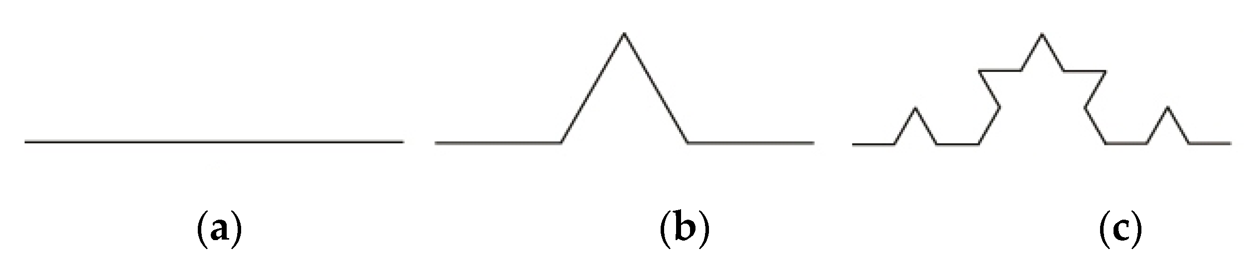
  • Tilt the structure’s elements to reduce size while maintaining comparable resonant frequencies. For this purpose, a printed fractal dipole is studied at first, as shown in Figure 2a.
  • The structure’s elements are extended inwards, as shown in Figure 2b,c.
  • The structure is parametrically studied to identify parts where it resonates in the desired bands. For better matching, a parametric study on different parts of the antenna is conducted. The lower side of the radiating element is modified and parametrically optimized, as seen in Figure 2d.
  • For further miniaturization, one element is removed and is replaced with a ground plane at the bottom of the substrate, cutting the structure’s width almost in half, as shown in Figure 2e. This results in a slight degradation in terms of performance.
  • For further miniaturization, the antenna’s sides are flattened and parametrically studied to ensure comparable behavior to the initial design.
  • After all modifications are done, the structure’s matching is enhanced again by creating and tuning two parts, “A” and “B”, as shown in Figure 3, where:
    A: is the space resonating in the MICS band;
    B: is the space resonating in the ISM 2.4 GHz band.
Region B is shaped into a rectangle. Its dimensions are defined following a parametric study for best matching. In the MICS band, the enhancement is obtained by applying several extensions at the tips of region A. Region 3 is where the reflection coefficient is enhanced. Table 1 shows the different antenna dimensions’ values:
Overall, the proposed antenna has a volume of 64.65 mm3, and dimensions equivalent to (2.3% × 3.6% × 0.03%) λ at 400 MHz and (14.01% × 12.1% × 0.2%) λ at 2.4 GHz.

2.2. Simulation

The antenna was simulated using the Ansys High Frequency Simulation System—HFSS—in a single layer-mimicking environment to facilitate the measurement and validation procedure, as shown in Figure 4.
The simulation was carried out in two configurations. In Figure 4a, the antenna is submerged in a 200 × 200 × 200 mm3 cube filled with a skin mimicking phantom, as it is intended to be placed subcutaneously in the arm 2 mm below the skin. The first simulation phases were performed in the configuration presented in Figure 4a. Due to simulator’s limitations, the antenna was excited using an internal ideal port. To consider the use of an external connector, including its dimensions, the second configuration, shown in Figure 4b, was used. It consisted of putting a 17.2 × 14.8 × 200 mm3 skin mimicking phantom above the antenna to simulate placement of a commercially available U.FL connector as an external port in order to take into account its effects during simulation. The U.FL connector was used because of its small dimensions and to simplify connection between the antenna and the devices.
Human skin is characterized by certain electrical parameters, including permittivity and conductivity. They depend on the frequencies of the signals used. In the MICS and ISM 2.4 GHz bands, these parameters are εr = 46.787, σ = 0.68807 S/m, and εr = 38.063, σ = 1.4407 S/m, respectively [9]. The simulated S11 coefficient of the antenna presented in Figure 4b configuration is shown in Figure 5a,b.
The simulated results indicate that in the MICS band, the parameter S11 has a value of −32.18 dB at 402.5 MHz. The frequency band in which the S11 coefficient is less than −10 dB runs from 395 to 409 MHz (a bandwidth of 14 MHz). In the ISM 2.4 GHz band, the antenna exhibits relatively wide-band behavior. The S11 remains below −10 dB at 2.33 to 2.51 GHz (a bandwidth of 180 MHz), and a minimum reflection coefficient equal to −19.65 dB is obtained at 2.42 GHz. A parametric study was performed in case there was a mismatch on any of these bands for any reason. Samples of the modified antennas with different dimensions are presented in Figure 6a–d, and the resulting S11 parameters are shown in Figure 7a,b for the MICS and ISM 2.4 GHz bands, respectively. Figure 7a shows that different values of the “Lm7” parameter residing in the radiating region of the MICS band contribute to the shifting of the resonant frequency, without degrading the impedance matching of the antenna. Figure 7b shows a similar behavior in the ISM band, where the “Wext” parameter helps in shifting the resonant frequency without strongly affecting the impedance matching. The shifting in terms of frequency in one band does not affect the other, allowing one to perform frequency-independent tuning. The frequency shifting sensitivity obtained by tuning the mentioned parameters is not the same: in the MICS band, shifting the resonant frequency from 402.5 MHz to 390 MHz requires a variation of 4.8 mm in the “Lm7” parameter, whereas in the ISM 2.4 GHz band, it takes only 0.5 mm of difference to shift the resonant frequency from 2.42 to 2.51 GHz. Region B is therefore more vulnerable to structural modifications.
The simulated radiation patterns of the structure in both bands are shown in Figure 8a,b.
The antenna exhibits quasi-omnidirectional radiation patterns in both MICS and ISM 2.4 GHz bands. Gain values reach −42.97 and −19.82 dBi in these bands, respectively. The obtained low gain values are due to the low profile of the antenna and the lossy environment it is placed in.

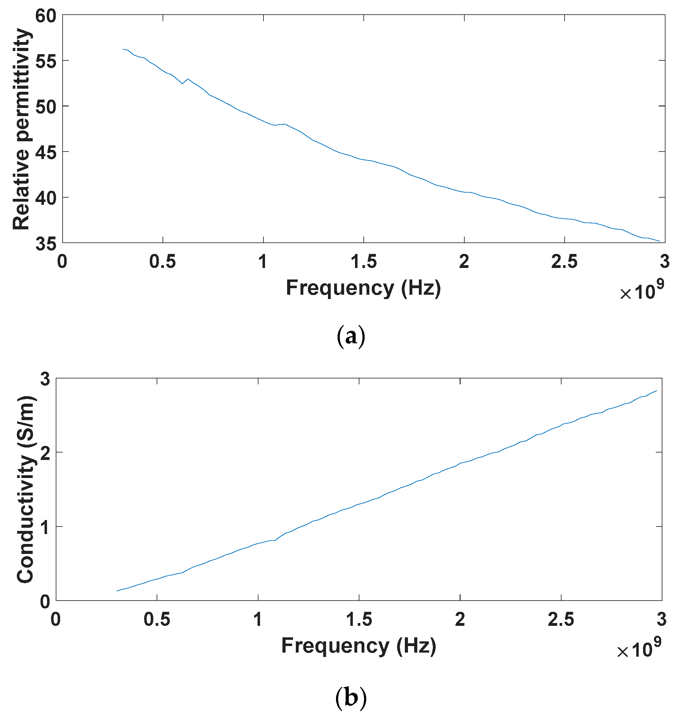
3. Tissue-Mimicking Phantom Characterization

To validate the various results obtained by simulation, measurements must be carried out either in vivo or in vitro. For the latter, the environment simulating real conditions must imitate the biological tissues of interest. The antenna is designed to operate at a depth of 2 mm below the skin of the human arm. Thus, a phantom mimicking human skin was required. In the literature, a variety of mixtures exist, two of which are the sugar/NaCl and Triton X-100/DGBE/NaCl formulas. A parametric study was performed to establish the validity and accuracy of these formulas. For the study conducted in this work, the Keysight 85070E open-ended coaxial probe was used for characterization, and the configuration is presented in Figure 9.

3.1. Sugar/NaCl Mixture

The composition of this formula is based on widely available components: sugar and an electrolyte, which in this case was regular salt, sodium chloride (NaCl), mixed in deionized water. The desired dielectric parameters can be achieved by adjusting these components. Permittivity is dependent on the quantity of sugar added into the mixture, whereas the electrolyte helps with adjusting the conductivity. However, as seen in [4], at higher frequencies, and particularly in the ISM 2.4 GHz band, the formula obtained shows that although the permittivity can be accurately controlled, the conductivity increases drastically without the use of NaCl, exceeding the desired values uncontrollably. For the ISM 2.4 GHz band, a trial was carried out to analyze the dielectric properties of a mixture comprised of 100 mg of sugar dissolved in 100 mL of deionized water. The obtained results are shown in Figure 10.
As can be seen in Figure 10a,b, both permittivity and conductivity increase proportionally to the amount of added sugar without adding salt. With the addition of 100 mg of sugar, the dielectric parameters obtained were εr = 38.08 and σ = 2.24 S/m, though there was an overshoot in the desired conductivity, as expected. Moreover, aside from the inability to control a crucial parameter, the dissolution of sugar is slow because of its high concentration. This makes this formula unreliable for making phantoms for high-frequency bands.

3.2. Triton X-100/DGBE Mixture

This formula requires essentially two commercially available ingredients: Triton X-100 and DGBE. These allow mixing a liquid with the desired dielectric parameters of human tissues in the bands of interest [6]. Additional ingredients are used [10], but for the phantoms required to validate the performance of the presented antenna, only NaCl was used. Figure 11, Figure 12, Figure 13 and Figure 14 show various parametric studies at the MICS and ISM 2.4 GHz bands with different amounts of ingredients added to 100 mL of deionized water.
Figure 11 and Figure 12 show the parametric study conducted to identify the quantity of each ingredient required to create a skin-mimicking phantom for the MICS band. Note that 100 mL of H2O and 20 mL of Triton X-100 were used, and DGBE was gradually added before adding NaCl. The addition of DGBE significantly changes the relative permittivity, whereas the conductivity marginally does so. With values ranging from 10 to 45 mL of DGBE, the dielectric parameters shifted from εr = 59.39 and σ = 0.07 S/m to εr = 47.1 and σ = 0.08 S/m. The permittivity obtained was close that one of human skin, the difference being 0.66%. NaCl was then gradually added to shift the phantom’s conductivity to the desired value. With the addition of up to 1 g by a step of 200 mg, the relative permittivity changed slightly, but the conductivity increased greatly. The dielectric parameters shifted to εr = 48.67 and σ = 0.60 S/m. The differences were 4% and 13% from the actual permittivity and conductivity of the skin, respectively.
Figure 13 and Figure 14 show the parametric study conducted for the ISM band phantom. A mixture of Triton X-100 and DGBE was added with quantities varying from 20 to 30 mL and 20 to 55 mL of each ingredient, respectively. At 2.4 GHz, the dielectric parameters of the mixture varied from εr = 53.55 and σ = 1.36 S/m to εr = 39.04 and σ = 1.48 S/m, the differences being 2.5% and 2.6% from the desired values, respectively. This slight variation in conductivity is satisfactory and does not require the addition of NaCl. Table 2 contains the final formulas for the phantoms:

4. Results and Discussion

The fabricated antenna and the configuration used to measure its radiation pattern are shown in Figure 15a,b.
To validate the performance of the structure obtained in the simulation, the S11 parameter had to be measured in a skin mimicking environment. For this, the antenna was placed in a plastic vial that was thin enough not cause any significant interference, at a distance from the surface of 2 mm, to simulate implantation below the skin of a human arm. It was then filled with the skin-mimicking liquids, the formulas of which are presented in Table 2, for measurements in the MICS and ISM 2.4 GHz bands. The results are shown in Figure 16.
The results of the MICS configuration are shown in Figure 16a. The S11 parameter measured in this band is in good agreement with the simulation results. It reached a value of −17.56 dB at 410 MHz, and the frequency band in which S11 < −10 dB was 399 to 422 MHz, giving a total bandwidth of 23 MHz, which includes the whole MICS band.
In the ISM band, as shown in Figure 16b, offsets of 251 and 517 MHz were observed with respect to the simulation, and broadband behavior was still observed. The band in which S11 < −10 dB ranged from 1.84 to 2.03 GHz, covering a total bandwidth of 190 MHz, and the minimum value of the S11 measured was −17.04 dB at 1.908 GHz. A smaller peak was also observed at 2.17 GHz, reaching −11.1 dB, and the S11 < −10 dB band ranged from 2.14 to 2.21 GHz, giving a total bandwidth of 70 MHz. The shifting was due to various factors that affected the antenna’s performance in general, but noticeably at higher frequencies: adhesives were used to glue the substrate and the superstrate, and to insulate the contact point at the U.FL connector to avoid any possible short-circuits. Furthermore, contrary to a simulation, the real life non-ideal gluing of the substrate and the superstrate would lead to the presence of impurities between the dielectrics, such as air bubbles. Manufacturing tolerances are also a contributing factor. Due to limitations related to hardware availability, the prototype fabrication process was affected, preventing the desired frequency correction, which could be obtained by changing the “Wext” value, as observed in the simulation shown in Figure 7b.
The radiation pattern measured in the ISM 2.4 GHz band is shown in Figure 17. The figure includes simulation results as well for comparison.
Although the antenna was not matched at exactly the desired band, the measured radiation pattern still exhibited higher gain values than those obtained from the simulation at the ISM band, with values reaching up to −18.66 and −17.00 dBi in the azimuth and elevation radiation patterns, respectively. These values would be improved with the correction of the resonant frequency offset in the ISM 2.4 GHz band.
Measurements in the MICS band were not conducted because of the limitations of the measuring hardware, as it does not tolerate lower frequencies, including the band of interest.
The pattern distortions in both measurements were likely due to impurities and adverse effects in the environment in which the antenna was tested, contrary to the ideal conditions in the simulation.
Table 3 presents different structures found in the literature compared to the presented antenna.

5. Conclusions

In this paper, a simple approach was used to design a low-profile, dual-band miniature antenna, designed to be implanted below the skin of the human arm. Its design was derived from the first iteration of the Koch fractal structure, and its dimensions are 17.2 × 14.8 × 0.254 mm3. It resonates in the MICS and ISM 2.4 GHz bands, and has no need for a matching circuit or the use of a via for miniaturization. The antenna is characterized by a satisfying performance despite its size compared to what is found in the literature. The structure has also more advantages in terms of simplicity of the design, and the ease of independently changing the resonant frequencies. To validate results obtained from the simulation, two formulas reproducing human skin from a dielectric point of view were compared, and two mimicking phantoms were created using the Keysight 85070E open-ended coaxial probe. The fabricated antenna resonated in the MICS band with a peak at 410 MHz and had two more resonant frequencies close to the ISM 2.4 GHz band. The second resonant frequency was 1.908 GHz, and the third peak was at 2.17 GHz. The bandwidth of the peaks were 23, 190, and 70 MHz, respectively. A measured gain levels of −18.66 and −17 dBi in the azimuth and elevation radiation patterns were obtained in the ISM 2.4 GHz band. The shifting of resonant peaks in the ISM 2.4 GHz band was due to parasitic effects brought on by adhesives, and manufacturing tolerances and impurities between the dielectrics that led to a noticeable effect on performance at higher frequencies. The correction of such shifting, although simple to perform, was limited due to the limited availability of the hardware, which affected prototype fabrication.

Author Contributions

Formal analysis, M.B.; methodology, M.B.; software, M.B.; writing—original draft preparation, M.B.; validation, H.D. and R.S.; supervision, G.H., T.P.V., P.M.M. and H.T.; review and editing, G.H., H.D., R.S., T.P.V., P.M.M. and H.T. All authors have read and agreed to the published version of the manuscript.

Funding

This research received no external funding.

Informed Consent Statement

Not applicable.

Data Availability Statement

Data is contained within the article.

Acknowledgments

The authors would like to thank Nicolas Corrao for his tremendous efforts throughout the challenging fabrication process of the preliminary models at the HYPER platform, IMEP-LaHC, University of Grenoble Alpes. R. Silva would like to thank FCT for grant 2021.06819.BD. All individuals included in this section have consented to the acknowledgement.

Conflicts of Interest

The authors declare no conflict of interest.

References

  1. Raza, Y.; Yousaf, M.; Abbas, N.; Akram, A.; Amin, Y. A High Gain Low-profile Implantable Antenna for Medical Applications. In Proceedings of the 2021 IEEE Asia Pacific Conference on Wireless and Mobile (APWiMob), Bandung, Indonesia, 8–10 April 2021; pp. 253–257. [Google Scholar]
  2. Abbas, N.; Manzoor, B.; Yousaf, M.; Zahid, M.; Bashir, Z.; Akram, A.; Amin, Y. A Compact Wide Band Implantable Antenna for Biotelemetry. In Proceedings of the 2019 Second International Conference on Latest trends in Electrical Engineering and Computing Technologies (INTELLECT), Karachi, Pakistan, 13–14 November 2019; pp. 1–5. [Google Scholar]
  3. Lamkaddem, A.; Yousfi, A.E.; Abdalmalak, K.A.; Posadas, V.G.; Muñoz, L.E.G.; Segovia-Vargas, D. A Compact Design for Dual-band Implantable Antenna Applications. In Proceedings of the 2021 15th European Conference on Antennas and Propagation (EuCAP), Dusseldorf, Germany, 22–26 March 2021; pp. 1–3. [Google Scholar]
  4. Karacolak, T.; Hood, A.Z.; Topsakal, E. Design of a Dual-Band Implantable Antenna and Development of Skin Mimicking Gels for Continuous Glucose Monitoring. IEEE Trans. Microw. Theory Tech. 2008, 56, 1001–1008. [Google Scholar] [CrossRef]
  5. Pournoori, N.; Ma, S.; Sydänheimo, L.; Ukkonen, L.; Björninen, T.; Rahmat-Samii, Y. Compact Dual-Band PIFA Based on a Slotted Radiator for Wireless Biomedical Implants. In Proceedings of the 2019 IEEE International Symposium on Antennas and Propagation and USNC-URSI Radio Science Meeting, Atlanta, GA, USA, 7–12 July 2019; pp. 13–14. [Google Scholar]
  6. Fukunaga, K.; Watanabe, S.; Yamanaka, Y. Dielectric properties of tissue-equivalent liquids and their effects on specific absorption rate. IEEE Trans. Electromagn. Compat. 2004, 46, 126–129. [Google Scholar] [CrossRef]
  7. Damaj, A.W.; Misilmani, H.M.E.; Chahine, S.A. Implantable Antennas for Biomedical Applications: An Overview on Alternative Antenna Design Methods and Challenges. In Proceedings of the 2018 International Conference on High Performance Computing & Simulation (HPCS), Orléans, France, 16–20 July 2018; pp. 31–37. [Google Scholar]
  8. Hamzah, S.A.; Raimi, M.K.; Abdullah, N.; Zainal, M.S. Design, Simulation, Fabrication and Measurement of a 900MHZ Koch Fractal Dipole Antenna. In Proceedings of the 2006 4th Student Conference on Research and Development, Shah Alam, Malaysia, 27–28 June 2006; pp. 1–4. [Google Scholar]
  9. Gabriel, S.; Lau, R.W.; Gabriel, C. The dielectric properties of biological tissues: III. Parametric models for the dielectric spectrum of tissues. Phys. Med. Biol. 1996, 41, 2271–2293. [Google Scholar] [CrossRef] [PubMed] [Green Version]
  10. Yilmaz, T.; Karacolak, T.; Topsakal, E. Characterization of Muscle and Fat Mimicking Gels at MICS and ISM Bands (402–405 MHz and 2.40–2.48 GHz). In Proceedings of the XXIX General Assembly of the International Union of Radio Science, Chicago, IL, USA, 7–16 August 2008. [Google Scholar]
Figure 1. Koch fractal curve: (a) no iterations applied to a segment line; (b) first iteration applied; (c) second iteration applied.
Electronics 12 01475 g001
Figure 2. Different iterations obtained throughout the optimization process: (a) first Koch iteration resonating at 2.4 GHz; (b) modified Koch structure; (c) extended modified Koch structure for lower frequency resonance; (d) modified structure for better matching; (e) single-element structure.
Electronics 12 01475 g002
Figure 3. Final proposed structure: (a) face view; (b) side view with mounted U.FL connector.
Electronics 12 01475 g003
Figure 4. Antenna simulation conditions (a) in a homogenous skin-mimicking phantom (b) with the U.FL connector.
Electronics 12 01475 g004
Figure 5. Simulated reflection coefficient of the antenna in the (a) MICS band and (b) ISM 2.4 GHz band.
Electronics 12 01475 g005
Figure 6. Proposed structure with different parameter variations: (a) Lm7 = 1.9 mm, (b) Lm7 = 6.7 mm, (c) Wext = 11.6 mm, (d) Wext = 11.1 mm.
Electronics 12 01475 g006
Figure 7. Reflection coefficient of the antenna with variations in the resonant frequency in the (a) MICS band and (b) ISM band.
Electronics 12 01475 g007
Figure 8. Simulated radiation pattern in (a) the MICS band and (b) the ISM band.
Electronics 12 01475 g008
Figure 9. Phantom characterization setup (Keysight E5071C VNA and Keysight 85070E dielectric probe kit).
Electronics 12 01475 g009
Figure 10. Dielectric properties of 100 mg of sugar dissolved in 100 mL of deionized water: Variations in (a) relative permittivity and (b) conductivity.
Electronics 12 01475 g010
Figure 11. Relative permittivity with various DGBE and NaCl concentrations.
Electronics 12 01475 g011
Figure 12. Conductivity with various DGBE and NaCl concentrations.
Electronics 12 01475 g012
Figure 13. Relative permittivity with various Triton X-100 and DGBE concentrations.
Electronics 12 01475 g013
Figure 14. Conductivity with various Triton X-100 and DGBE concentrations.
Electronics 12 01475 g014
Figure 15. Fabricated dual-band antenna: (a) face view and size; (b) immersed in mixed skin-mimicking liquid inside the anechoic chamber.
Electronics 12 01475 g015
Figure 16. Simulated and measured S11 parameters with skin mimicking phantom designed for the (a) MICS band and (b) ISM band.
Electronics 12 01475 g016
Figure 17. Simulated and measured radiation patterns of the proposed antenna at the ISM 2.4 GHz band in terms of (a) azimuth and (b) elevation.
Electronics 12 01475 g017
Table 1. Proposed antenna’s dimensions.
ParameterValue (mm)
L17.2
W14.8
Dielectric thickness0.127
Sl0.7
Sw1.6
Sd11.8
Sd21
Lm19
Lm24.1
Lm35.3
Lm47.5
Lm53.9
Lm67.4
Lm71.9
Lmw0.1
Lio0.3
Wio0.1
Le13.2
Le22
Wext11.6
Lma0.1
Lia4.5
Wia10.4
Table 2. Phantom formulas for skin-mimicking tissues at the MICS and 2.4 GHz ISM bands.
IngredientMICS PhantomISM 2.4 Phantom
Triton X-100 (mL)2030
DGBE (mL)4555
NaCl (g)1-
Deionized water (mL)100100
Table 3. Comparison between the presented work and recent work.
ReferenceVolume (mm3)Frequency (MHz)Bandwidth (MHz)Gain (dBi)Via
[1]12.82450290−14Yes
[2]9.82450420−15Yes
[3]91.44915
2450
-
-
−13.14 (meas)
−28 (meas)
No
[4]1265.63400
2450
141.2
170.4
-
-
Yes
[5]261.25−915
2450
200
450
−26.71
−17.5
Yes
This work64.65400
2450
23 (meas)
190 (meas)
−42.97
−17 (meas)
No
Disclaimer/Publisher’s Note: The statements, opinions and data contained in all publications are solely those of the individual author(s) and contributor(s) and not of MDPI and/or the editor(s). MDPI and/or the editor(s) disclaim responsibility for any injury to people or property resulting from any ideas, methods, instructions or products referred to in the content.

