1. Introduction
The demand for broadband wireless communication has seen explosive growth, accelerating the development of physical layer technology in wireless communication [
1]. To improve the communication capacity of wireless networks, mmWave and THz massive multiple-input multiple-output (MIMO) technologies are expected to be promising solutions [
2,
3,
4]. This method utilizes the short wavelength property of mmWave and THz, thus allowing more antennas to be placed in a fixed size. In particular, the array element is tens of times larger than traditional microwave arrays, which significantly improves the gain of antenna arrays, and enables multiple beams to serve multiple users simultaneously. Hundreds or even thousands of antennas can be arranged in some scenarios with less strict constraints on physical size.
However, despite the apparent advantages of mmWave and THz, there are many challenges to overcome in practice. The massive signal bandwidth in mmWave and THz communication puts more constraints on the sampling rate of the analog-to-digital converter (ADC), digital-to-analog converter (DAC), and other devices. Moreover, high-speed ADC and DAC, along with fewer quantization bits, make it challenging to meet the requirement of high-order modulation, such as orthogonal frequency division multiplexing (OFDM). Instead, simple modulation, such as binary phase shift keying (BPSK) or on-off keying (OOK), is adopted. In addition, in the case of a considerable number of antennas in massive MIMO, the hardware cost and complexity of all-digital structures will be unacceptably high. Therefore, the hybrid structure is usually applied to simplify the system design. Meanwhile, the number of RF chains can be reduced to a great extent by using shifters and combiners [
5].
Furthermore, we tend to adopt the DFT matrix to construct the shifter matrix in a hybrid structure. The massive antenna array can allocate each user an independent RF chain to form a beam pointing to the user. Benefiting from the vast size array as well as narrow beams, we reap good interuser orthogonal performance. However, narrow beams are susceptible to angle changes. Additionally, a tiny fluctuation of angle will cause a sharp deterioration in performance, resulting in an inevitable requirement for high-accuracy channel estimations. While the traditional DFT matrix is applied to building the analog matrix, the number of users will be limited by the number of RF chains. It is necessary to redesign the beam to take advantage of the limited RF chains to service more users.
The idea of multi-user beamforming in uplink is to design the received beam pattern without sacrificing any users’ signal–noise ratio (SNR). Multicast beamforming in a single group of the network is discussed in [
6], where all users request public information from transmitters. Its application is expanded to scenarios with multiple groups of networks in [
7,
8], where different user groups request a variety of information from transmitters.
There are two different formulated problems in the design of traditional multi-user beams: minimizing the transmission power while meeting the minimum required SNR (QoS problem), and maximizing the minimum SNR that meets the total transmission power limit (MMF problem). Both issues have been proved NP-hard in [
6], leading to a flurry of research activities in approximation techniques suitable for different scenarios. In this paper, we reconsider the design problem of multi-user beamforming at the receiver. The basic idea is to maximize the minimum SNR of the received signal to satisfy the shifter’s constant modulus constraint. In [
6], the two formulated problems are approximated as semi-definite programming (SDP) issues, which can be addressed by the modern interior point method. The authors of [
9] developed a successive linear approximation (SLA) algorithm for QoS problems, which is based on second-order cone programming (SOCP). A multiplicative update (MU) algorithm based on proportional fair proxy is proposed in [
10], which is essentially the geometric smoothing of the minimum required SNR. Experimental results in [
10] show that the minimum attainable SNR of MU-SLA is equivalent to that of SLA, but higher than those of all other algorithms. The average calculation time of MU-SLA is lower than that of SLA, but longer than those of all other gradient-based methods.
Based on the proposed analog matrix, we further discuss the simultaneous demodulation of simple modulated signals transmitted between the BS and users with fewer RF chains. This is an optimization problem of underdetermined observations with modulation constraints, and we propose a GAMP method, which is a demodulation method realized by iterative message-passing algorithms [
11,
12].
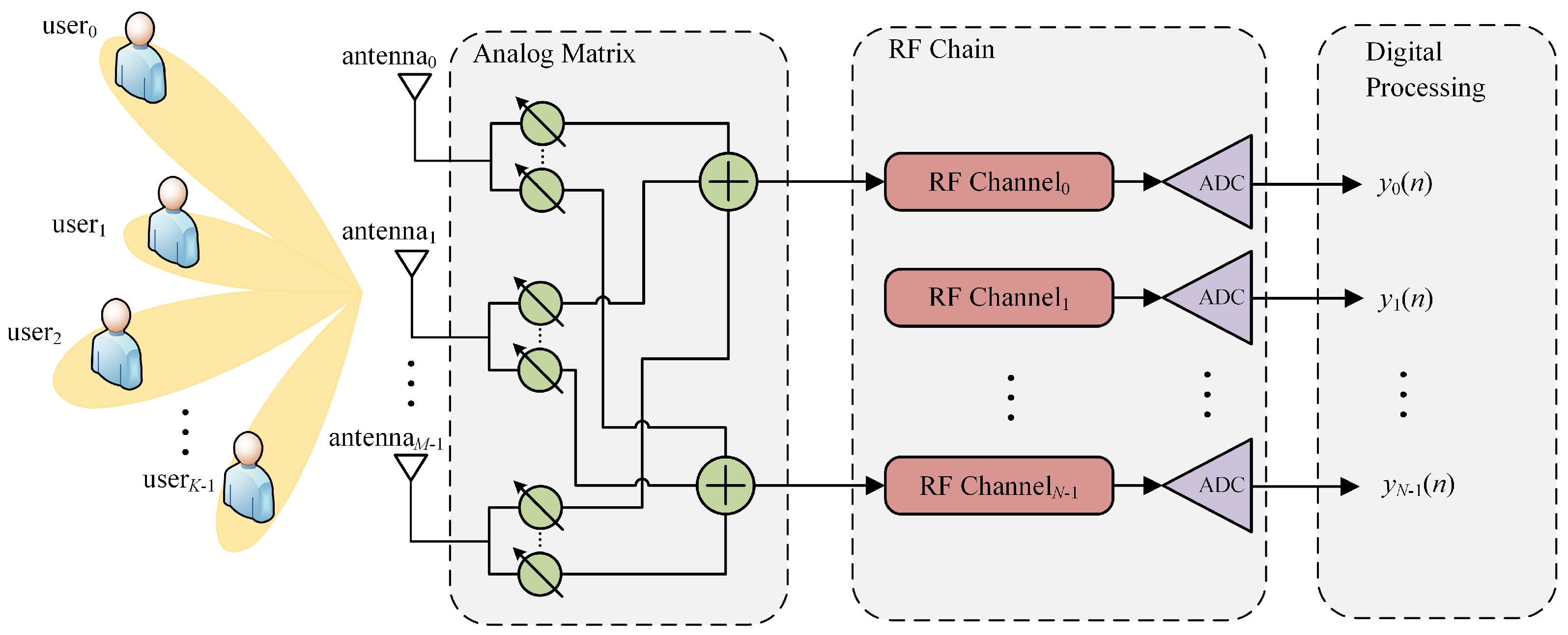
2. System Model
Assuming that a massive BS is equipped with
M antennas and
N RF chains (
N <
M), which are expected to simultaneously service
K single-antenna users [
2,
13] as shown in
Figure 1, the signal received by the BS is the sum of signals transmitted by several users, and it can be given by [
14]
where
y is the
N × 1-dimensional received signal,
is the adopted analog matrix,
w is the noise,
is the channel matrix, and
is the signal vector sent by
K users. Given the incident angle of user
k, namely
, the
N × 1 channel vector
between user
k and the BS is expressed as
Generally, for the BS, N > K is the precondition to ensure that each user is assigned an independent RF chain. Conversely, in some exceptional cases where N < K, it is impossible to realize ‘one user, one chain’.
Further, since the matrix is not of total rank, the minimum mean square error (MMSE) estimation of x is not available by using the least square (LS) method according to the traditional view. Nevertheless, x is usually generated by simple modulation such as BPSK, there is still room for improvement in the estimator, which is supposed to follow a Gaussian distribution.
Therefore, we first propose an analog matrix designing scheme that is effective in scenarios where K > N. That means the loss of some users’ signals can be avoided despite the absence of one-to-one correspondence between users and RF chains. Subsequently, a method based on the GAMP algorithm is developed, which can still achieve accurate reception of BPSK signals when K > N.
3. Analog Matrix Designing Scheme
For massive arrays, the sharp increase in the array elements results in extraordinarily narrow and high-gain beams, which can accurately aim at the target user and improve the SNR of the received signal. However, with the beams of highly high directivity, the power of signals transmitted by users beyond the beams will deteriorate to a great extent. This characteristic plays an active role in inter-users interference suppression for the traditional multi-user system. However, for a scenario with a large number of users, a few narrow beams can only cover some users, which may bring about a loss of information.
Therefore, based on the traditional DFT matrix and random phase matrix, this paper develops an analog matrix applicable for multi-user scenarios [
15]. Regarded as an MMF problem, the beam synthesizer designing problem can be written as follows:
Given that the
M is far greater than
N, and
w is statistically independent and obeys circular Gaussian distribution,
in the denominator can be given by
Hence, the original problem can be converted into
Based on the vectorization method, we simplify (
5) into
where
represents the vectorized form of matrix
. In addition,
represents the channel covariance matrix. Then, we can build the simplified problem as
Due to the constant modulus constraints in (
7), it is a non-convex problem that is difficult to address by general convex optimization methods.
Thus, we construct a new objective function as follows:
The original objective function can be further transformed into the following convex function:
Formula (
9) can be handled by the gradient descent method. Specifically, the gradient is expressed as
The gradient update rule is given by
Since the shifter in this system has constant modulus characteristics, it is necessary to normalize the updated shifter coefficients as
4. BPSK Demodulator Based on GAMP Method
For traditional hybrid structure systems, each RF chain corresponds to one user. Once the number of users exceeds the number of RF chains, the extra users will be unable to communicate with the BS.
Section 3 presents an analog matrix designing method aiming to support simultaneous service for multiple users by limited RF chains. In this section, we propose a technique that enables the BS equipped with limited RF chains to receive BPSK data transmitted by multiple users. The received signal is expressed as
where
,
,
.
Therefore, for the traditional Bayesian estimation method, the optimal estimation of
z, namely,
, can be obtained as follows:
where
T represents the estimation matrix. Further, the optimization problem is given by
Subsequently, we take the derivative of the objective function, and then set the derivative to 0, as shown in (
16).
It can be obtained that the optimal form of the estimation matrix
T is
is not of full column rank, thus
cannot be obtained through the optimal Bayesian estimation. Further, we shift to use the prior modulation information to solve this problem. Since BPSK modulation is adopted, the distribution of
z can be written as follows:
In the GAMP method, to simplify the calculation, we use the central limit theorem to approximate the Gaussian distribution of the intermediate variables
z and
q on the premise of large signal dimensions [
16,
17,
18]. Thus, the conditional posterior distribution of
z and
q is represented by
Because of the Gaussian approximation, we acquire the expectation and variance of
z subject to the conditional posterior distribution, as shown in (
22) and (
23).
Meanwhile, since
is the product of two Gaussian distributions, the expectation and variance of
q can be expressed as
Further, the following definitions are made:
Therefore, the algorithm process is as follows:
First, the optimal Bayesian estimation is used for the initialization.
Then, we proceed to the iteration process, as shown in (
33)–(
40).
For z to be estimated, the GAMP algorithm will produce a series of estimated results along with their variance . The final is the modulation data of the corresponding user.
5. Simulation Results
In this section, we numerically evaluate the performance of the analog matrix designing method and the multi-user receiver algorithm based on GAMP.
5.1. Performance Simulation of Analog Matrix
The traditional beam generated by the DFT matrix has excellent spatial selectivity signifying the high gain in the target direction but poor gain in other regions, which will lead to a sharp deterioration in the SNR of signals from users out of the target direction. Conversely, the method based on the proposed analog matrix shows excellent gain performance in all directions without horrible cases. The spatial responses comparing the DFT analog matrix and the proposed analog matrix are illustrated in
Figure 2a. We simulate and compare the array gains obtained by methods based on the two matrices with the assumption of the hybrid array structure with six RF chains to service eight and ten users (see
Figure 2a,b respectively). Obviously, for the DFT matrix, it can only form a fixed number of six beams pointing to six users separately, which results in seriously insufficient array gains for the remaining users. As shown in
Figure 2a,b, users near 0° have a loss of nearly 25 dB in SNR, which causes serious deterioration of communication performance. For the proposed analog matrix, the simulation results demonstrate that the array allocates an independent beam for each user to ensure that the SNR of each user can meet the communication requirements. Despite the slight loss of 3 dB in array gains for target users, the proposed analog matrix is superior to the traditional method based on the DFT matrix with a performance improvement of 20–30 dB for the other users.
Figure 3a,b, respectively, show the array gains when 6 RF chains are applied to serving 12 and 24 users. The red curve represents the array gain performance of the analog matrix proposed in this paper, and the blue curve represents the array gain performance of the DFT matrix. The incident angle of the user is uniformly distributed in the interval [−90°, +90°]. Similar to the conclusion of
Figure 2, when the number of RF chains is only half or a quarter of the number of users, the beam generated based on the DFT matrix cannot cover all users. For the users in the target direction of the beam generated by the DFT matrix, the performance loss is only about 5 dB when the proposed analog matrix is used instead. For the vast majority of users who are not pointed to based on the DFT matrix, the proposed analog matrix has a gain advantage of more than 20 dB. This shows that the analog matrix designing method proposed in this paper is advantageous for making fewer RF chains serve more users without sacrificing the SNR seriously.
5.2. BPSK Receiver Performance
Taking the BPSK modulation as an example, this subsection aims to discuss the BER performance versus SNR obtained by the random phase matrix method and the proposed method under the assumption that multiple users share fewer RF chains. Specifically, we set N as 4, M as 16, 32, and 64, and K as 6, 8, and 10 separately.
In
Figure 4a,b, it is observed that the two analog matrices can realize the simultaneous reception of BPSK signal transmitted by multiple users through the GAMP method at high SNR. For a fixed
M, the BER performance degrades as
K increases. Similarly, for a fixed
K, with the increase in
M, the BER performance of the proposed method improved, while for the random phase matrix, the simulation results approximately remain unchanged. The reason is that the process based on a random phase matrix cannot afford coherent integration of user signals. In other words, when using the analog matrix to combine signals received by multiple antennas, noise accumulates, resulting in equivalently unchanged SNR characteristics. In contrast, our method manages the coherent integration of multiple users’ signals. Conclusively, the proposed analog matrix can reap a performance advantage by approximately 10 dB compared with the method based on the random phase matrix.
6. Conclusions
In this paper, we have developed a receiver designing scheme applied to scenarios where the number of RF chains is less than that of users using the mmWave and THz massive hybrid array. An analog phase shifter network design method is proposed according to the minimax criterion. Furthermore, we have developed a receiver algorithm based on the GAMP method to recover signals from multiple users through less observation information. The simulation results indicate that, compared with the traditional DFT matrix-based structure, the proposed hybrid structure can utilize limited RF chains to form more beams and serve more users, avoiding the ubiquity of null in the DFT matrix-based structure. Furthermore, our proposed GAMP algorithm can recover the modulation information and complete the demodulation of BPSK data transmitted by multiple users with fewer observed signals.
Author Contributions
Conceptualization, X.D. and J.C.; methodology, X.D.; software, X.D. and D.L.; validation, X.D. and X.B.; formal analysis, D.L. and B.L.; writing—original draft preparation, X.D. and J.C.; writing—review and editing, X.B. and B.L.; supervision, X.B. All authors have read and agreed to the published version of the manuscript.
Funding
This research received no external funding.
Institutional Review Board Statement
Not applicable.
Informed Consent Statement
Not applicable.
Data Availability Statement
Data sharing not applicable.
Conflicts of Interest
The authors declare no conflict of interest.
References
- Ding, X.; An, J.; Zhao, Z.; Bu, X.; Yang, K. Low-Density Parity-Check Coded Direct Sequence Spread Spectrum Receiver Based on Analog Probabilistic Processing. IEEE Trans. Veh. Technol. 2021, 70, 6355–6370. [Google Scholar] [CrossRef]
- Zhao, J.; Gao, F.; Jia, W.; Zhang, S.; Jin, S.; Lin, H. Angle Domain Hybrid Precoding and Channel Tracking for Millimeter Wave Massive MIMO Systems. IEEE Trans. Wirel. Commun. 2017, 16, 6868–6880. [Google Scholar] [CrossRef]
- Pan, L.; Liang, L.; Xu, W.; Dong, X. Framework of Channel Estimation for Hybrid Analog-and-Digital Processing Enabled Massive MIMO Communications. IEEE Trans. Commun. 2018, 66, 3902–3915. [Google Scholar] [CrossRef]
- Song, H.J.; Nagatsuma, T. Present and Future of Terahertz Communications. IEEE Trans. Terahertz Sci. Technol. 2011, 1, 256–263. [Google Scholar] [CrossRef]
- Sohrabi, F.; Yu, W. Hybrid Digital and Analog Beamforming Design for Large-Scale Antenna Arrays. IEEE J. Sel. Top. Signal Process. 2016, 10, 501–513. [Google Scholar] [CrossRef]
- Sidiropoulos, N.; Davidson, T.; Luo, Z.Q. Transmit beamforming for physical-layer multicasting. IEEE Trans. Signal Process. 2006, 54, 2239–2251. [Google Scholar] [CrossRef]
- Karipidis, E.; Sidiropoulos, N.D.; Luo, Z.Q. Quality of Service and Max-Min Fair Transmit Beamforming to Multiple Cochannel Multicast Groups. IEEE Trans. Signal Process. 2008, 56, 1268–1279. [Google Scholar] [CrossRef]
- Xiang, Z.; Tao, M.; Wang, X. Coordinated Multicast Beamforming in Multicell Networks. IEEE Trans. Wirel. Commun. 2013, 12, 12–21. [Google Scholar] [CrossRef]
- Tran, L.N.; Hanif, M.F.; Juntti, M. A Conic Quadratic Programming Approach to Physical Layer Multicasting for Large-Scale Antenna Arrays. IEEE Signal Process. Lett. 2014, 21, 114–117. [Google Scholar] [CrossRef]
- Gopalakrishnan, B.; Sidiropoulos, N.D. High Performance Adaptive Algorithms for Single-Group Multicast Beamforming. IEEE Trans. Signal Process. 2015, 63, 4373–4384. [Google Scholar] [CrossRef]
- Al-Shoukairi, M.; Schniter, P.; Rao, B.D. A GAMP-Based Low Complexity Sparse Bayesian Learning Algorithm. IEEE Trans. Signal Process. 2018, 66, 294–308. [Google Scholar] [CrossRef]
- Xiong, Y.; Zhang, Z.; Wei, N.; Li, B. A Bilinear GAMP-Based Receiver for Quantized mmWave Massive MIMO Using Expectation Maximization. IEEE Commun. Lett. 2019, 23, 84–87. [Google Scholar] [CrossRef]
- Li, J.; Xiao, L.; Xu, X.; Zhou, S. Robust and Low Complexity Hybrid Beamforming for Uplink Multiuser MmWave MIMO Systems. IEEE Commun. Lett. 2016, 20, 1140–1143. [Google Scholar] [CrossRef]
- Nordio, A.; Taricco, G. Linear receivers for the multiple-input multiple-output multiple-access channel. IEEE Trans. Commun. 2006, 54, 1446–1456. [Google Scholar] [CrossRef]
- Zhou, L.; Zhou, X.; Chen, J.; Jiang, W.; Luo, W. Fast proximal gradient algorithm for single-group multicast beamforming. In Proceedings of the 2016 8th International Conference on Wireless Communications & Signal Processing (WCSP), Yangzhou, China, 13–15 October 2016; pp. 1–5. [Google Scholar]
- Yang, C.; Liu, X.; Guan, Y.L.; Liu, R. Fast GAMP Algorithm for Nonlinearly Distorted OFDM Signals. IEEE Commun. Lett. 2021, 25, 1682–1686. [Google Scholar] [CrossRef]
- Barbier, J.; Dia, M.; Macris, N. Universal Sparse Superposition Codes with Spatial Coupling and GAMP Decoding. IEEE Trans. Inf. Theory 2019, 65, 5618–5642. [Google Scholar] [CrossRef]
- Ma, Y.; Wu, N.; Zhang, J.A.; Li, B.; Hanzo, L. Generalized Approximate Message Passing Equalization for Multi-Carrier Faster-Than-Nyquist Signaling. IEEE Trans. Veh. Technol. 2022, 71, 3309–3314. [Google Scholar] [CrossRef]
| Disclaimer/Publisher’s Note: The statements, opinions and data contained in all publications are solely those of the individual author(s) and contributor(s) and not of MDPI and/or the editor(s). MDPI and/or the editor(s) disclaim responsibility for any injury to people or property resulting from any ideas, methods, instructions or products referred to in the content. |
© 2023 by the authors. Licensee MDPI, Basel, Switzerland. This article is an open access article distributed under the terms and conditions of the Creative Commons Attribution (CC BY) license (https://creativecommons.org/licenses/by/4.0/).


