
Double-Tuned Birdcage Radio Frequency Coil for 7 T MRI: Optimization, Construction and Workbench Validation

 , , , ,
Abstract
1. Introduction
2. Materials and Methods
3. Results
3.1. 4R Birdcage Model Optimization
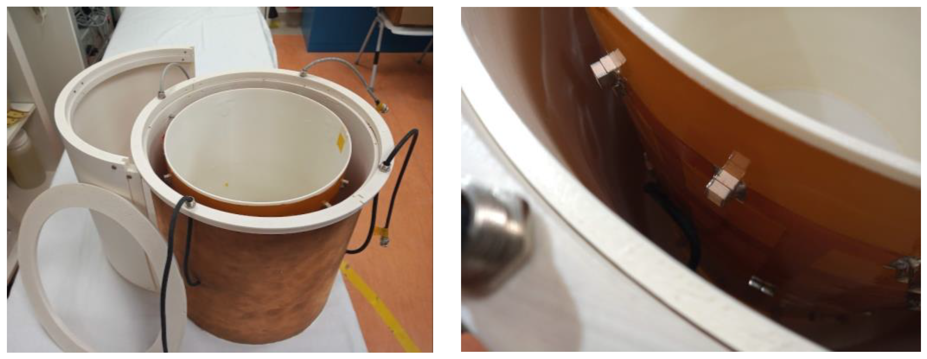
3.2. The Four-Ring DT-RF Coil Prototype Workbench Testing
4. Discussion
5. Conclusions
Author Contributions
Funding
Data Availability Statement
Acknowledgments
Conflicts of Interest
References
- Hayes, C.E.; Edelstein, W.A.; Schenck, J.F.; Mueller, O.M.; Eash, M. An efficient, highly homogeneous radiofrequency coil for whole-body NMR imaging at 1.5 T. J. Magn. Reson. 1985, 63, 622–628. [Google Scholar] [CrossRef]
- Tropp, J. The theory of the bird-cage resonator. J. Magn. Reson. 1989, 82, 51–62. [Google Scholar] [CrossRef]
- Leifer, M.C. Resonant Modes of the Birdcage Coil. J. Magn. Reson. 1997, 124, 51–60. [Google Scholar] [CrossRef]
- Tropp, J. Mutual inductance in the bird-cage resonator. J. Magn. Reson. 1997, 126, 9–17. [Google Scholar] [CrossRef] [PubMed]
- Mispelter, J.; Lupu, M.; Briguet, A. NMR Probeheads for Biophysical and Biomedical Experiments: Theoretical Principles & Practical Guidelines, 2nd ed.; Imperial College Press: London, UK, 2015. [Google Scholar]
- Fantasia, M.; Galante, A.; Maggiorelli, F.; Retico, A.; Fontana, N.; Monorchio, A.; Alecci, M. Numerical and workbench design of 2.35 T double-tuned (1H/23Na) nested RF birdcage coils suitable for animal size MRI. IEEE Trans. Med. Imaging 2020, 39, 3175–3186. [Google Scholar] [CrossRef]
- Isaac, G.; Schnall, M.D.; Lenkinski, R.E.; Vogele, K. A design for a Double-Tuned Birdcage Coil for Use in an Integrated MRI/MRS Examination. J. Magn. Reson. 1990, 89, 41–50. [Google Scholar] [CrossRef]
- Shen, G.X.; Boada, F.E.; Thulborn, K.R. Dual-frequency, dual-quadrature, birdacge RF coil design with identical B1 pattern for sodiu and proton imaging of the human brain at 1.5 T. Magn. Reson. Med. 1997, 38, 717–725. [Google Scholar] [CrossRef] [PubMed]
- Matson, G.B.; Vermathen, P.; Hill, T.C. A practical double-tuned 1H/31P quadrature birdcage headcoil optimized for 31P operation. Magn. Reson. Med. 1999, 42, 173. [Google Scholar] [CrossRef]
- Giovannetti, G.; Valvano, G.; Virgili, G.; Giannoni, M.; Flori, A.; Frijia, F.; De Marchi, D.; Hartwig, V.; Landini, L.; Aquaro, G.D.; et al. Design and simulation of a dual-tuned 1H/23Na birdcage coil for MRS studies in human calf. Appl. Magn. Reson. 2015, 46, 1221–1238. [Google Scholar] [CrossRef]
- Fitzsimmons, J.R.; Beck, B.L.; Brooker, H.R. Double resonant quadrature birdcage. Magn. Reson. Med. 1993, 30, 107–114. [Google Scholar] [CrossRef] [PubMed]
- Asfour, A. A three-coil RF probe-head at 2.35 T: Potential applications to the 23Na and to the hyperpolarized 129Xe MRI in small animals. In Proceedings of the 2010 Annual International Conference of the IEEE Engineering in Medicine and Biology, Buenos Aires, Argentina, 31 August–4 September 2010; pp. 5693–5699. [Google Scholar] [CrossRef]
- Brand, R.C.; Webb, A.G.; Beenakker, J.M. Design and Performance of a Transformer-Coupled Double Resonant Quadrature Birdcage Coil for Localized Proton and Phosphorus Spectroscopy in the Human Calf Muscle. Conc. Magn. Reson. 2013, 42, 155–164. [Google Scholar] [CrossRef]
- Murphy-Boesch, J.; Srinivasan, R.; Carvajal, L.; Brown, R.R. Two configurations of the four-ring birdcage coil for 1H imaging and 1H decoupled 31P spectroscopy of the human head. J. Magn. Reson. 1994, B103, 103–114. [Google Scholar] [CrossRef] [PubMed]
- Ha, Y.; Choi, C.H.; Worthoff, W.A.; Shymanskaya, A.; Schöneck, M.; Willuweit, A.; Felder, J.; Shah, N.J. Design and use of a folded four-ring double-tuned birdcage coil for rat brain sodium imaging at 9.4 T. J. Magn. Reson. 2018, 286, 110–114. [Google Scholar] [CrossRef] [PubMed]
- Lanz, T.; von Kienlin, M.; Behr, W.; Haase, A. Double-tuned four-ring birdcage res-onators for in vivo 31P-nuclear magnetic resonance spectroscopy at 11.75 T. Magn. Reson. Mat. Phys. Biol. Med. 1997, 5, 243–246. [Google Scholar] [CrossRef]
- Wiggins, G.C.; Brown, R.; Lakshmanan, K. High-performance radiofrequency coils for 23Na MRI: Brain and musculoskeletalapplications. NMR Biomed. 2016, 29, 96–106. [Google Scholar] [CrossRef] [PubMed]
- Murphy-Boesch, J. Double-tuned birdcage coils: Construction and tuning. In eMagRes; Harris, R.K., Wasylishen, R.L., Eds.; John Wiley & Sons: Hoboken, NJ, USA, 2011. [Google Scholar] [CrossRef]
- Shan, K.; Duan, Y. Rapid four-ring birdcage coil analysis: Design optimization for high efficiency, low interference, and improved body loading tolerance. Magn. Reson. Imag. 2019, 66, 30–35. [Google Scholar] [CrossRef] [PubMed]
- Hong, S.M.; Choi, C.H.; Shah, N.J.; Felder, J. Design and evaluation of a 1H/31P double-resonant helmet coil for 3T MRI of the brain. Phys. Med. Biol. 2019, 64, 035003. [Google Scholar] [CrossRef] [PubMed]
- Findeklee, C.; Leussler, C.; Morich, M.; Demeester, G. Efficient Design of a novel Double Tuned Quadrature Headcoil for Simultaneous 1H and 31P MRI/MRS at 7T. Proc. Intl. Soc. Mag. Reson. Med. 2005, 13, 891. [Google Scholar]
- Hilal, S.K.; Maudsley, A.A.; Simon, H.E.; Perman, W.H.; Bonn, J.; Mawad, M.E.; Silver, A.J.; Ganti, S.R.; Sane, P.; Chien, I.C. In vivo NMR imaging of tissue sodium in the intact cat before and after acute cerebral stroke. Am. J. Neuroradiol. 1983, 4, 245–249. [Google Scholar]
- Boada, F.E.; LaVerde, G.; Jungreis, C.; Nemoto, E.; Tanase, C.; Hancu, F. Loss of cell ion homeostasis and cell viability in the brain: What sodium MRI can tell us. Curr. Top. Dev. Biol. 2005, 70, 77–101. [Google Scholar] [CrossRef] [PubMed]
- Thulborn, K.R.; Gindin, T.S.; Davis, D.; Erb, P. Comprehensive MR imaging protocol for stroke management: Tissue sodium concentration as a measure of tissue viability in nonhuman primate studies and in clinical studies. Radiology 1999, 213, 156–166. [Google Scholar] [CrossRef] [PubMed]
- Thulborn, K.R.; Davis, D.; Snyder, J.; Yonas, H.; Kassam, A. Sodium MR imaging of acute and subacute stroke for assessment of tissue viability. Neuroimag. Clin. N. Am. 2005, 15, 639–653. [Google Scholar] [CrossRef]
- Sandstede, J.J.W.; Hillenbrand, H.; Beer, M.; Pabst, T.; Butter, F.; Machann, W.; Bauer, W.; Hahn, D.; Neubauer, S. Time course of 23Na signal intensity after myocardial infarction in humans. Magn. Reson. Med. 2004, 52, 545–551. [Google Scholar] [CrossRef] [PubMed]
- Pabst, T.; Sandstede, J.; Beer, M.; Kenn, W.; Greiser, A.; von Kienlin, M.; Neubauer, S.; Hahn, D. Optimization of ECG-triggered 3D 23Na MRI of the human heart. Magn. Reson. Med. 2001, 45, 164–166. [Google Scholar] [CrossRef] [PubMed]
- Sandstede, J.W.; Pabst, T.; Beer, M.; Lipke, C.; Baurle, K.; Butter, F.; Harre, K.; Kenn, W.; Voelker, W.; Neubauer, S.; et al. Assessment of myocardial infarction in humans with 23Na MR imaging: Comparison with cine MR imaging and delayed contrast enhancement. Radiology 2001, 221, 222–228. [Google Scholar] [CrossRef] [PubMed]
- Maril, N.; Rosen, Y.; Reynolds, G.H.; Ivanishev, A.; Ngo, L.; Lenkinski, R.E. Sodium MRI of the human kidney at 3 Tesla. Magn. Reson. Med. 2006, 56, 1229–1234. [Google Scholar] [CrossRef]
- Steidle, G.; Graf, H.; Schick, F. Sodium 3-D MRI of the human torso using a volume coil. Magn. Reson. Imag. 2004, 22, 171–180. [Google Scholar] [CrossRef] [PubMed]
- Wheaton, A.J.; Borthakur, A.; Shapiro, E.M.; Regatte, R.R.; Akella, S.V.S.; Kneeland, J.B.; Reddy, R. Proteoglycan loss in human knee cartilage: Quantitation with sodium MR imaging—Feasibility study. Radiology 2004, 231, 900–905. [Google Scholar] [CrossRef] [PubMed]
- Insko, E.K.; Clayton, D.B.; Elliott, M.A. In vivo sodium MR imaging of the intervertebral disk at 4 T. Acad. Radiol. 2002, 9, 800–804. [Google Scholar] [CrossRef] [PubMed]
- Weber, M.A.; Nielles-Vallespin, S.; Essig, M.; Jurkat-Rott, K.; Kauczor, H.U.; Lehmann-Horn, F. Muscle Na+ channelopathies—MRI detects intracellular 23Na accumulation during episodic weakness. Neurology 2006, 67, 1151–1158. [Google Scholar] [CrossRef] [PubMed]
- Constantinides, C.D.; Gillen, J.S.; Boada, F.E.; Pomper, M.G.; Bottomley, P.A. Human skeletal muscle: Sodium MR imaging and quantification-potential applications in exercise and disease. Radiology 2000, 216, 559–568. [Google Scholar] [CrossRef] [PubMed]
- Schmitt, B.; Zbyn, S.; Stelzeneder, D.; Jellus, V.; Paul, D.; Lauer, L.; Trattnig, S. Cartilage Quality Assessment by Using Glycosaminoglycan Chemical Exchange Saturation Transfer and 23Na RM Imaging at 7T. Radiology 2011, 260, 257–264. [Google Scholar] [CrossRef] [PubMed]
- Ouwerkerk, R.; Bleich, K.B.; Gillen, J.S.; Pomper, M.G.; Bottomley, P.A. Tissue sodium concentration in human brain tumors as measured with 23Na MR imaging. Radiology 2003, 227, 529–537. [Google Scholar] [CrossRef]
- Nielles-Vallespin, S.; Weber, M.A.; Bock, M.; Bongers, A.; Speier, P.; Combs, S.E.; Wohrle, J.; Lehmann-Horn, F.; Essig, M.; Schad, L.R. 3D radial projection technique with ultrashort echo times for sodium MRI: Clinical applications in human brain and skeletal muscle. Magn. Reson. Med. 2007, 57, 74–81. [Google Scholar] [CrossRef] [PubMed]
- Hoult, D.; Chen, C.; Sank, V. Quadrature detection in the laboratory frame. Magn. Reson. Med. 1984, 1, 339–353. [Google Scholar] [CrossRef] [PubMed]
- Stara, R.; Fontana, N.; Tiberi, G.; Monorchio, A.; Manara, G.; Alfonsetti, M.; Galante, A.; Vitacolonna, A.; Alecci, M.; Retico, A.; et al. Validation of numerical approaches for electromagnetic characterization of magnetic-resonance radio-frequency coils. Prog. Electromagn. Res. M 2013, 29, 121–136. [Google Scholar] [CrossRef]
- MS 3-2008 R2014; Determination of Image Uniformity in Diagnostic Magnetic Resonance Images. National Electrical Manufacturers Association NEMA Standards Publication: Rosslyn, VA, USA, 2021.
- Tropp, J. The theory of an arbitrarily perturbed birdcage resonator and a Simple Method for Restoring It to Full Symmetry. J. Magn. Reson. 1991, 95, 235–243. [Google Scholar] [CrossRef]


| Homogeneity (%) | |||
|---|---|---|---|
| lNa = 160 mm (Figure 3) | |||
| gapER = 24 mm | gapER = 36 mm | ||
| @f1H | 44 | @f1H | 50 |
| @f23Na | 97 | @f23Na | 97 |
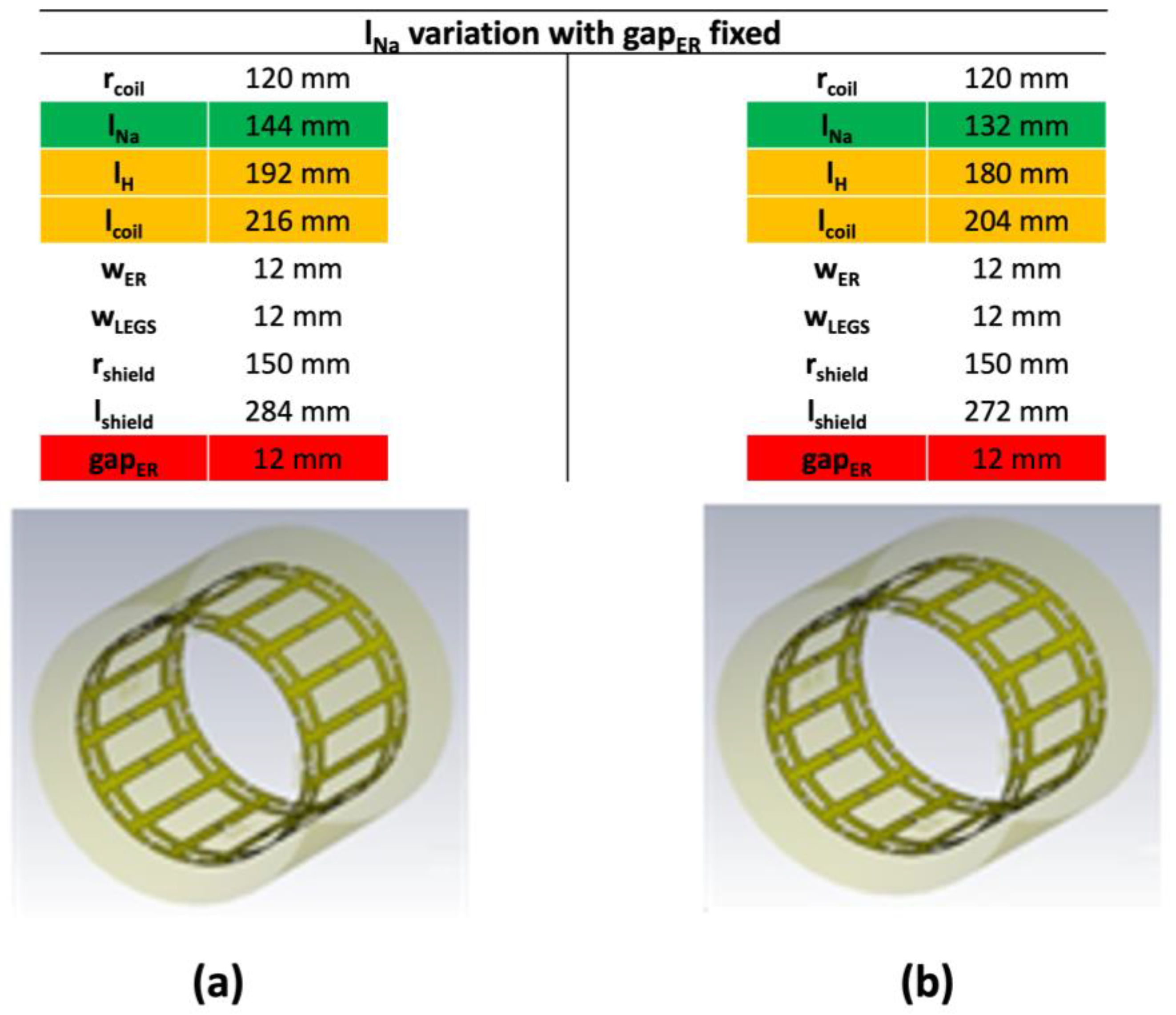
| gapER = 12 mm (Figure 4) | |||
| lNa = 144 mm | lNa = 132 mm | ||
| @f1H | 36 | @f1H | 32 |
| @f23Na | 97 | @f23Na | 97 |
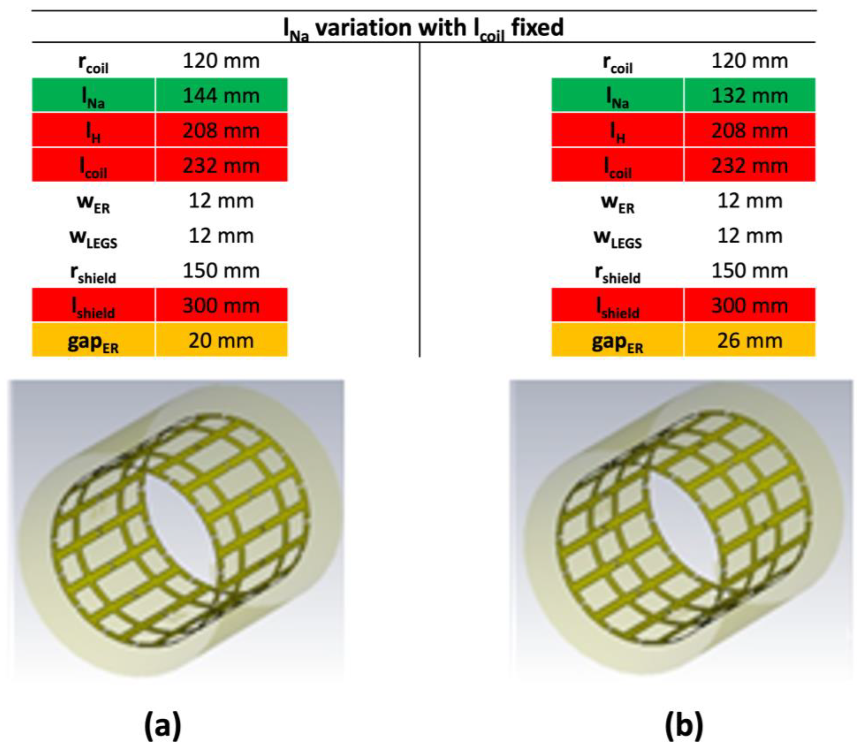
| lcoil = 232 mm (Figure 5) | |||
| lNa = 144 mm | lNa = 132 mm | ||
| @f1H | 38 | @f1H | 45 |
| @f23Na | 97 | @f23Na | 96 |
| Sii Parameters (dB) after Matching | |||
|---|---|---|---|
| lNa = 160 mm (Figure 3) | |||
| gapER = 24 mm | gapER = 36 mm | ||
| S11 (f1H) | −27 | S11 (f1H) | −22 |
| S33 (f23Na) | −23.8 | S33 (f23Na) | −30 |
| gapER = 12 mm (Figure 4) | |||
| lNa = 144 mm | lNa = 132 mm | ||
| S11 (f1H) | −17 | S11 (f1H) | −16 |
| S33 (f23Na) | −29 | S33 (f23Na) | −32 |
| lcoil = 232 mm (Figure 5) | |||
| lNa = 144 mm | lNa = 132 mm | ||
| S11 (f1H) | −14 | S11 (f1H) | −18 |
| S33 (f23Na) | −32 | S33 (f23Na) | −32 |
| Efficiency () | |||
|---|---|---|---|
| lNa = 160 mm (Figure 3) | |||
| gapER = 24 mm | gapER = 36 mm | ||
| @f1H | 1.8 | @f1H | 1.8 |
| @f23Na | 3.0 | @f23Na | 3.0 |
| gapER = 12 mm (Figure 4) | |||
| lNa = 144 mm | lNa = 132 mm | ||
| @f1H | 1.5 | @f1H | 1.7 |
| @f23Na | 3.0 | @f23Na | 2.9 |
| lcoil = 232 mm (Figure 5) | |||
| lNa = 144 mm | lNa = 132 mm | ||
| @f1H | 1.6 | @f1H | 1.7 |
| @f23Na | 2.9 | @f23Na | 2.9 |
| Unloaded | Qunloaded (f23Na) | 387 |
| Qunloaded (f1H) | 337 | |
| Loaded | Qloaded (f23Na) | 181 |
| Qloaded (f1H) | 172 |
| Sii Parameters (dB) | |
|---|---|
| S11 (f1H) | −24 |
| S22 (f1H) | −20 |
| S21 (f1H) = S12 (f1H) | −15 |
| S33 (f23Na) | −14 |
| S44 (f23Na) | −16 |
| S43 (f23Na) = S34 (f23Na) | −16 |
Disclaimer/Publisher’s Note: The statements, opinions and data contained in all publications are solely those of the individual author(s) and contributor(s) and not of MDPI and/or the editor(s). MDPI and/or the editor(s) disclaim responsibility for any injury to people or property resulting from any ideas, methods, instructions or products referred to in the content. |
© 2023 by the authors. Licensee MDPI, Basel, Switzerland. This article is an open access article distributed under the terms and conditions of the Creative Commons Attribution (CC BY) license (https://creativecommons.org/licenses/by/4.0/).
Share and Cite
Retico, A.; Maggiorelli, F.; Giovannetti, G.; Boskamp, E.; Robb, F.; Fantasia, M.; Galante, A.; Alecci, M.; Tiberi, G.; Tosetti, M. Double-Tuned Birdcage Radio Frequency Coil for 7 T MRI: Optimization, Construction and Workbench Validation. Electronics 2023, 12, 901. https://doi.org/10.3390/electronics12040901
Retico A, Maggiorelli F, Giovannetti G, Boskamp E, Robb F, Fantasia M, Galante A, Alecci M, Tiberi G, Tosetti M. Double-Tuned Birdcage Radio Frequency Coil for 7 T MRI: Optimization, Construction and Workbench Validation. Electronics. 2023; 12(4):901. https://doi.org/10.3390/electronics12040901
Chicago/Turabian StyleRetico, Alessandra, Francesca Maggiorelli, Giulio Giovannetti, Eddy Boskamp, Fraser Robb, Marco Fantasia, Angelo Galante, Marcello Alecci, Gianluigi Tiberi, and Michela Tosetti. 2023. "Double-Tuned Birdcage Radio Frequency Coil for 7 T MRI: Optimization, Construction and Workbench Validation" Electronics 12, no. 4: 901. https://doi.org/10.3390/electronics12040901
APA StyleRetico, A., Maggiorelli, F., Giovannetti, G., Boskamp, E., Robb, F., Fantasia, M., Galante, A., Alecci, M., Tiberi, G., & Tosetti, M. (2023). Double-Tuned Birdcage Radio Frequency Coil for 7 T MRI: Optimization, Construction and Workbench Validation. Electronics, 12(4), 901. https://doi.org/10.3390/electronics12040901