Article

A Checkpointing Recovery Approach for Soft Errors Based on Detector Locations

1
School of Information Engineering, Tianjin University of Commerce, Tianjin 300134, China
2
School of Computer Science and Engineering, Southeast University, Nanjing 211189, China
*
Authors to whom correspondence should be addressed.
Electronics 2023, 12(4), 805; https://doi.org/10.3390/electronics12040805
Submission received: 31 December 2022 / Revised: 21 January 2023 / Accepted: 3 February 2023 / Published: 6 February 2023
(This article belongs to the Special Issue Software Reliability: Status and Perspectives)

Abstract

:
Soft errors are transient errors caused by single-event effects (SEEs) resulting from a strike by high-energy particles acting on sensitive areas of integrated circuits. Soft errors frequently occur in the space environment, adversely affecting the reliability of aerospace-based computing. A recovery process is launched to recover the program when soft errors are detected. A periodic checkpointing recovery approach is widely utilized to prevent soft errors. However, this approach does not consider the detector locations, resulting in a large time overhead. This paper proposes a checkpointing recovery approach for soft errors based on detector locations called DLCKPT. DLCKPT reduces the time overhead by considering detector locations. The experimental results show that the percentage decrease in the time overhead between the DLCKPT and the periodic checkpointing recovery approach is 13.4%. The average recovery rate and average space overhead are 99.3% and 44.4% for the periodic checkpointing recovery approach and 99.4% and 34.6% for the DLCKPT. These results show that the DLCKPT and the periodic checkpointing recovery approach produce comparable results for the recovery rate. The DLCKPT has a lower time overhead and a slightly lower space overhead than the periodic checkpointing recovery approach, demonstrating its effectiveness.

1. Introduction

Soft errors are caused by energetic particles striking sensitive areas of integrated circuits, such as alpha particles and cosmic neutrons generated by packaging materials or radiation [1,2]. The first reports of failures attributed to cosmic rays emerged in 1975 when space-borne electronics malfunctioned [3,4]. Today’s integrated circuits have higher integration and operating speeds. Therefore, they are more sensitive to soft errors [5]. Soft errors are transient faults. They do not permanently damage hardware, and the hardware operates normally after transient faults have occurred. However, soft errors influence data stored in registers and memory cells, impacting the accuracy of software computations.
Soft errors are a significant threat to software reliability. Therefore, soft error protection is essential [6]. Soft error protection includes soft error detection and recovery. The former detects soft errors, and the latter ensures recovery from soft errors. Soft error protection is conducted at both the hardware and software levels [7,8,9]. Hardware-based technology usually changes the processor architecture or attaches special-purpose hardware modules to the processor. It is expensive and typically not portable [10]. Due to the low-cost and applicability requirements, most soft error protection solutions have been developed and widely applied at the software level [11].
Soft error recovery ensures that a program operates correctly after a soft error has occurred. Software-based soft error recovery is conducted at the compiler level and the source code level. At the compiler level, instruction duplication and signature-based mechanisms are applied. The instruction duplication mechanism duplicates instructions and performs majority voting to recover from soft errors [12,13]. The signature-based mechanism detects soft errors using a signature of a program block. The system recovers from soft errors by transferring control back to the program block that was executed before the soft errors occurred [14].
At the source code level, duplication-based and checkpoint-based mechanisms are applied. The duplication-based mechanism uses redundant variables to execute a recovery. The checkpoint-based mechanism performs recovery by checkpoint and recovery operations [15]. The checkpoint operation generates a checkpoint with data representing a copy of the current state of a process. The recovery operation is launched in the event of a failure. This operation recovers the process to a previously stored state by a checkpoint and continues from there. The soft error recovery mechanism at the source code level has been widely studied and implemented because it is straightforward and has a low cost. However, the following two challenges exist.
(1) The duplication-based recovery approach at the source code level generates redundant copies of variables. Soft errors are handled by utilizing redundant copies and original copies. However, it requires users to modify the source code of programs; thus, this is not a lightweight approach. Figure 1 provides an example; x is the original copy, and y is the AN-encoded copy of x, which is set to 3 x . AN-codes are a class of arithmetic codes where the codeword is the original data multiplied by a constant. When 3 x is not equal to y, an error has occurred. If y is divisible by 3, then x is corrupted. In this case, y is used to correct x. Otherwise, y is corrupted, and x is used to correct y. If x is 2, y is set to 6. As shown in Figure 1, after the execution of line 1 and line 2, the values of x and y are stored in registers or memory cells. During the execution of line 3 and line 4, when a soft error occurs in x, the 3rd bit of x is changed from 0 to 1 so that the value of x is 10 (00001010) rather than 2 (00000010). In the following program execution, the error is detected in line 5 when the relationship is not satisfied, i.e., y 3 x . In this case, the value of y is used to correct x (lines 6–7). After the recovery, the value of x is corrected to 2. Figure 1 shows that the source code has been modified, and multiple statements have been inserted. The original three lines of codes increases to nine lines of codes.
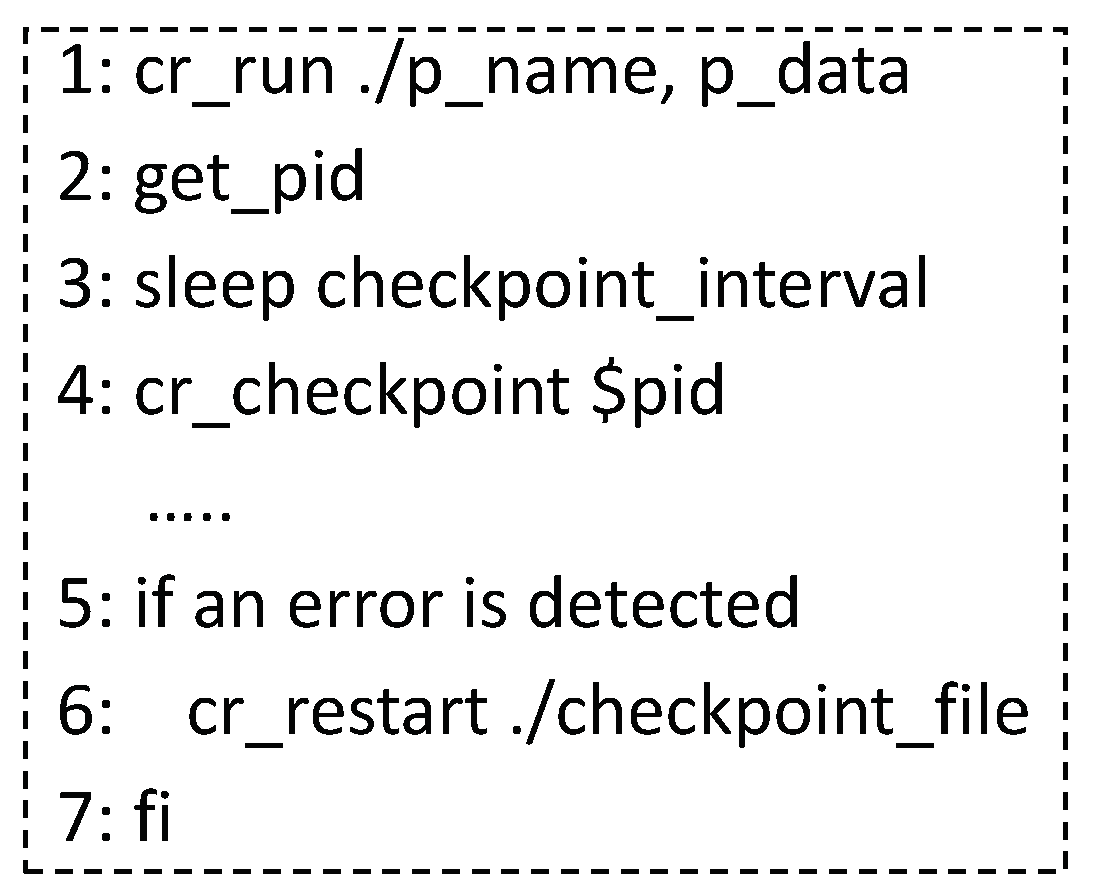
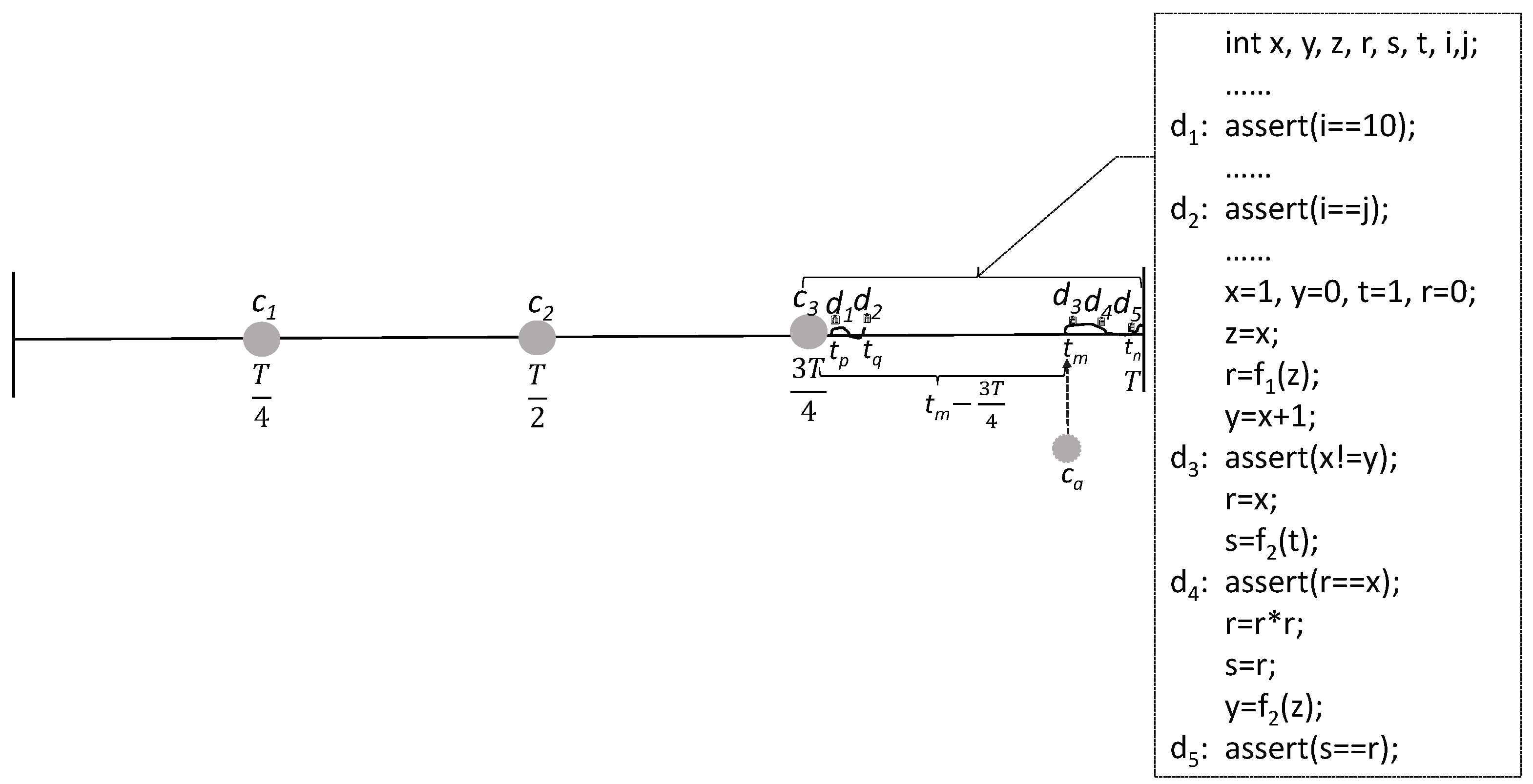
(2) Periodic checkpointing recovery is a popular checkpoint-based approach. It does not require users to modify the program’s source code. A shell script is usually used to launch the checkpoint and recovery operations to save the current state of a process and recover it to a previously stored state. Figure 2 provides an example; c r _ r u n , c r _ c h e c k p o i n t , and c r _ r e s t a r t are APIs provided by the checkpointing tool Berkeley Lab Checkpoint/Restart (BLCR) [15], c r _ r u n starts the program execution, c r _ c h e c k p o i n t launches the checkpoint operation for generating a checkpoint file, and c r _ r e s t a r t launches the recovery operation to resume the process execution by the checkpoint file. The periodic checkpointing recovery approach does not modify the program codes. However, its time overhead cannot be substantially decreased because it does not consider detector locations when it deploys checkpoints. For example, in Figure 3, T is the program execution time, and the checkpoint interval is T / 4 . C 1 , c 2 , and c 3 are checkpoints that are set during T. D 1 , d 2 , ⋯, and d 5 are detectors that are executed during the program execution of [ 3 T / 4 , T ] . The first two detectors have ranges of [ t p , t q ] , and the last three detectors have ranges of [ t m , t n ] . The rectangular box shows the code that is executed during [ 3 T / 4 , T ] . The five assertion statements represent five detectors, d 1 , d 2 , ⋯, and d 5 . When d 3 , d 4 , and d 5 detect an error, the error recovery time at the recent checkpoint c 3 is very long because the program is rolled back to c 3 and continues running from c 3 . The time of rolling back to c 3 is at least equal to the difference between t m and 3 T / 4 .
This paper proposes a checkpointing recovery approach for soft errors based on detector locations referred to as DLCKPT. This method executes soft error recovery with a low time overhead. DLCKPT does not require users to modify source codes, and its process is straightforward. Our main contributions are summarized as follows:
(1) A novel approach called DLCKPT is proposed for soft error recovery. DLCKPT recovers from soft errors by using checkpoint mechanism. DLCKPT deploys checkpoints by considering the location of detectors to reduce the time overhead. For example, as shown in Figure 3, when the error recovery time detected during [ t m , t n ] and using c 3 is longer than that of using the checkpoint c a , which is set before t m , the additional checkpoint c a is set before t m to reduce the time.
(2) A program is divided into multiple segments using checkpoints. The time overhead of each program segment is determined, including the checkpointing time and recovery time. The change in the time overhead of each program segment is evaluated when checkpoints are inserted or deleted, and the change is used to adjust the checkpoint deployment.
(3) Experiments are conducted with various programs to evaluate the effectiveness of DLCKPT. The result shows that DLCKPT reduces the time overhead by considering detector locations and does not adversely affect the recovery rate and space overhead, demonstrating its effectiveness.
The remainder of this paper is organized as follows: Section 2 briefly reviews related work. Section 3 introduces the preliminaries. Section 4 presents the overview of the proposed DLCKPT approach. The detailed process of DLCKPT is given in Section 5. Section 6 describes the experiment and results. Section 7 concludes the paper and discusses future work.

2. Related Work

Soft error recovery is an essential part of soft error protection. It recovers programs after soft errors have occurred. There is a significant body of work on software-based soft error recovery conducted at the compiler level and source code level.
The instruction duplication mechanism at the compiler level recovers programs from soft errors by applying redundant instructions. SWIFT-R [13] is a typical instruction duplication approach. It intertwines three copies of the instruction and uses majority voting before critical instructions, such as s t o r e instructions. Figure 4 presents an example. Before interacting with the memory cells, SWIFT-R determines the accuracy of the data using a 2-of-3 majority voting operation, which is represented by the “majority” function in Figure 4. In line 8, the m a j o r i t y ( r 1 , r 1 , r 1 ) means that the data in the three registers are set to the majority value. If r 1 = r 1 and r 1 r 1 , r 1 is set to r 1 to correct the data in r 1 . SWIFT-R performs soft error detection and recovery simultaneously on three copies. The cost of SWIFT-R is high because it adds many redundant instructions. S-SWIFT-R [16] is a selective SWIFT-R. It selects different register subsets from the microprocessor register file to be protected rather than protecting all registers. S-SWIFT-R is more flexible than SWIFT-R. However, there are still many redundant instructions in S-SWIFT-R. SWIFT-R and S-SWIFT-R only check the operands before executing critical instructions. They do not protect the result of the critical instructions. NEMESIS [17] was developed to improve soft error resilience and reduce the performance overhead. It compares the results rather than the operands of critical instructions. Although many efforts have been made to refine the duplication space, the cost of instruction duplication remains quite high.
Soft error recovery approaches at the source code level can be classified into duplication-based and checkpoint-based approaches. TRUMP [13] is a typical duplication-based approach. Figure 1 shows the recovery pseudo-code of TRUMP. x is the original copy, and y is the AN-encoded copy of x. y and x have a predefined relationship during normal program execution: y = 3 x . An error is detected if the relationship is not satisfied, namely, y 3 x . In the recovery mechanism, the corrupted copy is inferred by the relationship and is corrected by using the correct copy. The concept of duplication-based approaches is simple; however, many statements are required for insertion into source codes.
Checkpoint-based approaches achieve soft error recovery by preserving and restoring a historical state of a program. Coordinated checkpointing is widely used in parallel systems, where the nodes collectively reach a barrier that serves as a consistent state for restarting from a checkpoint. One problem of coordinated checkpointing is that it produces massive amounts of input/output (I/O) from nodes at the checkpoint barrier, resulting in a considerable time overhead. Amrizal et al. proposed a speculative checkpointing technique to tackle this problem [18]. They predicted whether a memory write was the last one before the next checkpoint and thus can be speculatively checkpointed early. Although this approach performed well, it is only applicable to parallel systems, limiting its wide applicability. The graph theory has been widely used in many research fields [19,20]. Sharanyan et al. used the graph theory and integer linear programming to set checkpoints for programs [21]. They partitioned the control flow and data flow graphs of the programs. Only variables used for further program execution were saved at the partition points. Although this approach reduces the size of checkpoints, i.e., the space overhead, it does not consider the time overhead. Periodic checkpointing recovery sets checkpoints at a fixed interval. However, the work of [22] demonstrated theoretically that this approach is not the optimal checkpointing strategy for reducing the time overhead. The authors did not propose a solution to optimize the method and did not focus on implementation.

3. Preliminaries

We first describe the fault tolerance process in checkpointing recovery to clarify the time overhead. Then, the necessity for considering the detection locations in deploying checkpoints is explained. The meanings of frequently used terms are listed in Table 1.
A program is blocked during a checkpoint operation and resumes after the operation. As shown in Figure 5, when no soft errors are detected during program execution, the overall program execution time is T + t 0 + t 1 + t 4 , where T is the original program execution time, and t 0 , t 1 and t 4 are the checkpointing times of the three checkpoints. T + t 0 + t 1 + t 4 represents the sum of the original program execution time and the checkpointing time. The fault tolerance time includes the checkpointing time and recovery time. In this case, the checkpointing time is the fault tolerance time since the recovery time is zero. If a soft error occurs and is detected by a detector during program execution, the program is rolled back to the latest checkpoint and resumes. If a soft error is detected at F, the program rolls back to c 2 and then continues executing until it ends. At this time, the overall program execution time is T + i = 0 4 t i , where t 2 is the time of restoring the data of c 2 , i.e., the recovery time of the historical state, and t 3 is the execution time from c 2 to F, i.e., the recovery time of the current state. T + i = 0 4 t i represents the sum of the original program execution time, the checkpointing time and the recovery time, i.e., the sum of the original program execution time and the fault tolerance time.
This description of the time overhead indicates that the overall program execution time decreases with a decrease in the fault tolerance time because the original program execution time does not change. Besides, a decrease in the overall program execution time also reflects a decrease in the fault tolerance time.
Soft errors can be categorized as crash, hang, benign, and silent data corruption (SDC) [10]. Crash and hang refer to a hardware exception and program timeout, respectively [23]. SDC means that an error causes an incorrect program result without any warnings [24]. Being benign means that an error is masked during program execution and does not affect the program results. Different variables or instructions produce different soft error types [9,24,25]. Detectors are placed at program points where errors with adverse effects or of high concern to users may occur to improve detection efficiency. As a result, the distribution of detectors in a program is asymmetric. Periodic checkpointing recovery does not consider the detector locations when setting checkpoints; thus, the time overhead of this method is high. As shown in Figure 5, the recovery time of the current state is very long when an error is detected in [ t m , t n ] . An additional checkpoint can be placed at t m when the checkpointing time at t m is short to reduce the time overhead. Therefore, it is necessary to consider the detection location in checkpointing recovery. The objective of this study is to reduce the time overhead of fault tolerance. Therefore, the checkpoints in the periodic checkpointing recovery approach are redeployed. The redeployment is conducted by evaluating the time overhead and considering the detector location.

4. Overview of the DLCKPT Approach

An overview of the DLCKPT approach is presented in Figure 6. It includes four parts. The first two parts perform preparation, such as deploying the initial checkpoints and assessing the time overhead. The last two parts redeploy the checkpoints based on the results of the first two parts.
The first part deploys initial checkpoints and generates program segments. Initial checkpoints are deployed for a program using the checkpointing interval (denoted by d in Figure 6) of the periodic checkpointing recovery approach. Then, the program is divided into multiple segments based on the initial checkpoints. As a result, every program segment has one checkpoint. The handling time of the errors detected by the detectors in a program segment is called the time overhead of the program segment. In the second part, the time overhead of each program segment is assessed by considering the detector locations. The time overhead includes the checkpointing time and recovery time.
The third part handles each program segment. It determines whether the checkpoints of a program segment are adequate and inserts additional checkpoints when they are inadequate. Additional checkpoints are initially inserted into the current program segment, and the time overhead is evaluated. If the time overhead is not reduced, the checkpoints are adequate. Otherwise, the checkpoints are inadequate. When the checkpoints are adequate, the process moves to the fourth part. Otherwise, additional checkpoints are inserted, and the next program segment is handled. It should be noted that adequate (inadequate) refers to the adequate (inadequate) number of checkpoints.
The fourth part determines whether the checkpoints of a program segment are redundant, in which case they are deleted. The checkpoints of a program segment are initially deleted, and its time overhead is evaluated. If the time overhead is reduced, the checkpoints are redundant and are deleted. Otherwise, the checkpoints are not redundant and cannot be deleted. When the current program segment has been handled, the process moves to the next program segment. When all program segments have been dealt with, the DLCKPT process ends.

5. The DLCKPT Approach

The four parts of the proposed DLCKPT approach are described in detail in Section 5.1, Section 5.2, Section 5.3 and Section 5.4, and the overall process of DLCKPT is presented in Section 5.5.

5.1. Deploy Initial Checkpoints and Generate Program Segments

The checkpoints of a program are deployed based on the checkpointing interval of the periodic checkpointing recovery approach. These checkpoints are called initial checkpoints. Then, the program segments are generated based on the initial checkpoints. Figure 7 shows the division of the program segments. At the program level, c 1 c n are checkpoints. They divide a program into n program segments, p 1 p n . At the instruction level, the dynamic instructions of the program are also divided into n instruction segments, s 1 s n . i 1 i n Δ s represents the dynamic instructions, where Δ s refers to the number of instructions in every instruction segment. The program execution time between two checkpoints is the same in the periodic checkpointing recovery. Therefore, the instruction segments typically have the same size when dynamic instructions are considered. The instructions of instruction segment s j are i m ( s j ) i j Δ s , where m ( s j ) is the number of the first instruction of s j . The value of m ( s j ) is expressed by Equation (1). As shown in Equation (1), m ( s j ) is related to the number of instructions in every instruction segment, i.e., Δ s and the number of s j , i.e., j.
m ( s j ) = ( j 1 ) × Δ s + 1 , j > 1 , 1 , j = 1 .

5.2. The Time Overhead of a Program Segment

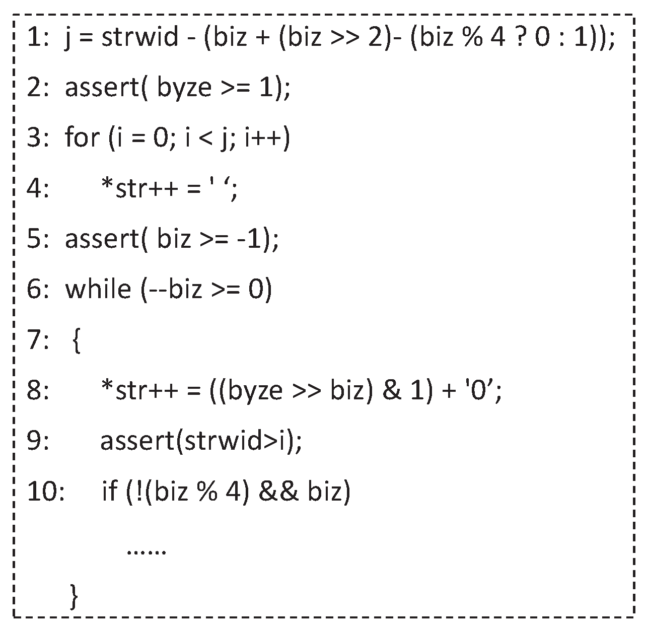
The time overhead of a program segment refers to the handling time of the errors detected by the detectors in the program segment, i.e., the fault tolerance time. Figure 8 presents an example to illustrate the time overhead. It shows the segment “bitstrng” with the detectors, where “bitstrng” is a program in the Mibench benchmark suite that prints a bit pattern of bytes formatted as a string. The detectors are widely applied program invariant assertions and are represented by the assertion statements [4,10] in lines 2, 5, and 9. In this case, the time overhead of this segment is the handling time of the errors detected by the assertion detectors.
The time overhead of a program segment consists of the checkpointing time and recovery time. The latter includes the recovery time of the historical state and the current state. Next, the evaluation of the time overhead is presented in detail. In Figure 9, it is assumed that the detector at F detects an error. In this case, the time overhead consists of the time to generate c j , i.e., the checkpointing time, the time to restore the data of c j , i.e., the recovery time of the historical state, and the execution time from c j to F, i.e., the recovery time of the current state. In this paper, we assume that the time to generate a checkpoint and the time to restore the checkpoint data are the same; therefore, the checkpointing time and the recovery time of the historical state are the same. The checkpointing time of c j is denoted as t c ( c j ) ; thus, the recovery time of the historical state can be represented by t c ( c j ) . Two checkpoints have different checkpointing times and recovery times of the historical state. They depend on the size of the checkpointing data. As mentioned above, the recovery time of the current state is the execution time from the latest checkpoint to the location where the error is detected. The recovery time of the current state can be represented by the execution time of the instructions between the latest checkpoint and the location where the error is detected. A program segment may have multiple detectors. Its recovery time of the current state is considered the average recovery time of the current state for all locations of the detectors. The recovery time of p j is defined in Equation (2), where the second item represents the recovery time of the current state, c ( p j ) is the number of dynamic detectors in p j , θ is the average execution time of one dynamic program instruction, and a ( p j , k ) is the instruction number of the k-th dynamic detector in p j . A detector at the program level corresponds to multiple instructions at the instruction level. In this paper, the number of the detector is the number of the first instruction corresponding to the detector. Finally, the time overhead of p j is expressed by Equation (3).
t r ( p j ) = t c ( c j ) + ( k = 1 c ( p j ) ( a ( p j , k ) m ( s j ) ) c ( p j ) × θ )
o ( p j ) = t c ( c j ) + t r ( p j )

5.3. Determine the Adequacy of Checkpoints

The time overhead of a program segment is evaluated after adding an additional checkpoint to determine if the checkpoints of the program segment are adequate. The additional checkpoint is only inserted into the middle of the program segment. If the time overhead is reduced after adding the checkpoint, the checkpoints of the program segment are inadequate. In this case, a checkpoint is inserted into the middle of the program segment. Otherwise, the checkpoints of the program segment are adequate, and no additional checkpoints are inserted. Next, we evaluate the change in the time overhead of p j when a checkpoint is inserted into the middle of p j .
In Figure 10, a checkpoint called a c j is inserted into the middle of p j . Then, p j is divided into two parts. The errors detected by the detectors in the second part of p j is handled by utilizing a c j rather than c j , changing the recovery time of p j . The new recovery time of p j is represented by Equation (6), where A is the recovery time of the historical state, B is the recovery time of the current state, u ( p j ) in B is the number of detectors in the first half of p j . The insertion of a c j also changes the checkpointing time of p j . The new checkpointing time of p j is expressed by Equation (7).
A = t c ( c j ) + t c ( a c j ) 2
B = k = 1 u ( p j ) ( a ( p j , k ) m ( s j ) ) + k = u ( p j ) + 1 c ( p j ) ( a ( p j , k ) ( m ( s j ) + Δ s 1 2 ) ) c ( p j ) × θ
t r ( p j ) = A + B
t c ( p j ) = t c ( c j ) + t c ( a c j )
The time overhead of p j after inserting a c j is defined in Equation (8), and the change in the time overhead of p j is expressed by Equation (9). Equation (9) indicates that the time overhead of p j is reduced when a g ( p j ) > 0 . In this case, the checkpoint of p j is inadequate; thus, a checkpoint is inserted into the middle of p j . Otherwise, the time overhead of p j is not reduced, indicating that the checkpoint of p j is adequate, and no additional checkpoints are required.
o ( p j ) = t r ( p j ) + t c ( p j )
a g ( p j ) = o ( p j ) o ( p j )

5.4. Determine the Redundancy of Checkpoints

The time overhead of a program segment is evaluated when its checkpoints are deleted to determine if the checkpoints are redundant. If they are redundant, they are deleted and vice versa.
In Figure 11, c j and c j 1 are the checkpoints of p j and p j 1 , respectively. We merge p j and p j 1 to create a new program segment, p m . In p m , the errors detected by the detectors in p j 1 are handled by utilizing c j 1 , and the errors detected by the detectors in p j are handled by utilizing c j . When c j is deleted, the errors detected by the detectors in p j are handled by utilizing c j 1 rather than c j , changing the time overhead of p j and p m . Since deleting c j does not affect the time overhead of p j 1 , the change in the time overhead of p m can be considered the change in the time overhead of p j . Next, we evaluate the change in the time overhead of p m to determine whether c j is redundant.
Equation (10) expresses the time overhead of p m when c j is not deleted. If it is deleted, the time overhead of p m changes. The new time overhead of p m is defined by Equation (11). Thus, the change in the time overhead of p m is expressed by Equation (12). Equation (12) indicates that the time overhead of p m is reduced when d g ( p m ) > 0 . In this case, the checkpoint of p j is redundant and can be deleted. Otherwise, the time overhead of p m is not reduced. Thus, the checkpoint of p j is not redundant and cannot be deleted.
o ( p m ) = k = 1 c ( p j 1 ) ( a ( p j 1 , k ) m ( s j 1 ) ) + k = 1 c ( p j ) ( a ( p j , k ) m ( s j ) ) c ( p j 1 ) + c ( p j ) × θ + t c ( c j 1 ) + t c ( c j ) 2 + t c ( c j 1 ) + t c ( c j )
o ( p m ) = k = 1 c ( p j 1 ) ( a ( p j 1 , k ) m ( s j 1 ) ) + k = 1 c ( p j ) ( a ( p j , k ) m ( s j ) + Δ s ) c ( p j 1 ) + c ( p j ) × θ + 2 × t c ( c j 1 )
d g ( p m ) = o ( p m ) o ( p m )

5.5. The Process of DLCKPT

This section describes the process of DLCKPT in detail. The processes of the first two parts of DLCKPT are presented in Algorithm 1. The inputs of Algorithm 1 are the checkpointing interval of the periodic checkpointing recovery approach and a program. They are denoted by Δ t and P, respectively. The outputs of Algorithm 1 are the program segments and their time overheads, which are represented by the sets P S and O H , respectively.
Algorithm 1 The Processes of the First Two Parts of DLCKPT
Require: 
Δ t , P
Ensure: 
P S , O H
  1:
acquire T and d i ( P ) by executing P
  2:
n = T / Δ t
  3:
deploy initial checkpoints, c 1 - c n
  4:
generate program segments, p 1 - p n
  5:
Δ s = s i z e ( d i ( P ) ) / n
  6:
θ = T / s i z e ( d i ( P ) )
  7:
for j = 1 n do
  8:
      determine m ( s j ) by (1)
  9:
      evaluate t c ( c j )
10:
      determine c ( p j ) based on d i ( P )
11:
       r = 0 , z = 0
12:
      for  k = 1 c ( p j )  do
13:
          get a ( p j , k )
14:
           r = r + ( a ( p j , k ) m ( s j ) )
15:
      end for
16:
       z = r c ( p j ) × θ
17:
      calculate t r ( p j ) by (2)
18:
      calculate o ( p j ) by (3)
19:
      put o ( p j ) into O H
20:
      put p j into P S
21:
end for
In Algorithm 1, the execution time and the dynamic instruction set of P are acquired by executing P (Line 1), which are denoted by T and d i ( P ) , respectively. Then the number of initial checkpoints is determined based on Δ t and T (Line 2). Next, the initial checkpoints are deployed, and program segments are generated (Lines 3–4). The size of every instruction segment and the average execution time of one program instruction are determined (Lines 5–6). The program segments are handled sequentially. First, the number of the first instruction is determined by Equation (1) (Line 8) for handling the current program segment. Then, the checkpointing time is evaluated (Line 9), and the number of dynamic detectors is determined (Line 10). Next, the sum of the number of the re-executed instructions in all detector locations is determined (Lines 12–15), which is represented by r. The re-executed instructions refer to the instructions that are re-executed during a recovery operation. The average recovery time for all detector locations is calculated by Equation (2) (Line 17). Further, the time overhead is calculated by Equation (3), and is inputted into the set of the time overhead of program segments, namely, O H (Lines 18–19). Finally, the current program segment is input into the set of program segments, namely, P S (Line 20).
The processes of the last two parts of DLCKPT are presented in Algorithm 2. The inputs of Algorithm 2 are the outputs of Algorithm 1, i.e., P S and O H . The output of Algorithm 2 is the set of redeployed checkpoints, R C . In Algorithm 2, the program segments are handled sequentially. An additional checkpoint is initially set in the middle of the current program segment (Line 3). Then, the number of detectors in the first half is determined (Line 4). The checkpointing time of the additional checkpoint is evaluated (Line 5). Next, the new average recovery time of the historical state and the current state for all detector locations are determined by Equations (4) and (5), respectively (Line 6). Next, the new recovery time and checkpointing time are calculated by Equations (6) and (7), respectively (Line 7). The new time overhead is determined by Equation (8) (Line 8). Finally, the change in the time overhead is obtained from Equation (9) (Line 9).
Algorithm 2 The Processes of the Last Two Parts of DLCKPT
Require: 
P S , O H
Ensure: 
R C
  1:
p l a s = p 1
  2:
for j = 1 n do
  3:
      set an additional checkpoint a c j in the middle of p j
  4:
      determine u ( p j )
  5:
      evaluate t c ( a c j )
  6:
      determine A and B by (4) and (5)
  7:
      calculate t r ( p j ) , t c ( p j ) by (6) and (7)
  8:
      determine o ( p j ) by (8)
  9:
      obtain a g ( p j ) by (9)
10:
      if  a g ( p j ) > 0  then
11:
          set a c j in the middle of p j at last
12:
          put c j and a c j into R C
13:
           p l a s = s e c o n d ( p j )
14:
          continue
15:
      else
16:
           p m = m e r g e ( p j , p l a s )
17:
          obtain o ( p m ) and o ( p m ) from (10) and (11)
18:
          calculate d g ( p m ) by (12)
19:
          if  d g ( p m ) < 0  then
20:
             put c j into R C
21:
              p l a s = p j
22:
          else
23:
             delete c j
24:
              p l a s = p m
25:
          end if
26:
      end if
27:
end for
When the change in the time overhead is greater than 0, an additional checkpoint is set in the middle of the current program segment, and the additional checkpoint and the original checkpoint of the current program segment are input into R C (Lines 11–12). The second half of the current program segment is considered the latest program segment, and the next program segment is handled (Line 13). At the beginning of Algorithm 2, the first program segment is considered the latest program segment. When the change in the time overhead is less than 0, the latest and current program segments are merged to create a new program segment, p m (Line 16). Then, the time overhead of p m is obtained from Equation (10). In addition, the time overhead of p m after deleting the checkpoint of the current program segment is obtained from Equation (11) (Line 17). The change in the time overhead of p m is calculated by Equation (12) (Line 18). When the change in the time overhead of p m is less than 0, the checkpoint of the current program segment remains and is input into R C (Line 20). The current program segment is then considered the latest program segment (Line 21). Otherwise, the checkpoint of the current program segment is deleted, and p m is considered the latest program segment (Lines 23–24).

6. Experiment and Results

An experiment was conducted to evaluate the DLCKPT approach. The experimental setup is presented in Section 6.1, and the results are described in Section 6.2. The overall program execution time, recovery rate, and space overhead of the DLCKPT are compared with the periodic checkpointing recovery approach.

6.1. Experimental Setup

Fault injection is widely used to simulate single-event effects (SEEs) and the resulting soft errors in experiments [4,10]. Pin is a binary instrumentation framework for the IA-32 and x86-64 instruction sets, enabling the creation of dynamic program analysis tools [26]. Similar to [4,10,24], Pin was used for fault injection by altering one bit in the register or memory cell from 0 to 1 or from 1 to 0. Besides, Pin was also used to create the dynamic instrument tool that was used for generating dynamic instructions and program segments. The dynamic instrument tool tracks the program execution and divides the program into multiple segments based on the program execution and checkpointing interval. The original program execution time was T. Two independent experiments were performed with different checkpointing intervals of the periodic checkpointing recovery: T / 4 and T / 3 . BLCR is a representative system-level checkpointing tool for the Linux platform [15]. It saves the entire state of a process to disk, such as the process ID, CPU registers and virtual memory, and later restores the state. The BLCR provides instructions to execute checkpoint and recovery operations. A user is only required to execute the instructions but does not have to implement them. We employed BLCR to execute the checkpoint and recovery operations. The platform for the experimental evaluation was Ubuntu 10.04, running on a Dell Workstation with an i7 processor. The pseudo-code of the procedure of checkpoint and recovery operations is shown in Figure 12. C r _ r u n , c r _ c h e c k p o i n t , and c r _ r e s t a r t are functions provided by the BLCR. First, c r _ r u n is used to run a program. An identification number of the process related to the program is obtained. Then, c r _ c h e c k p o i n t is executed to generate a checkpoint file after a checkpoint interval. Next, a fault is injected into the process. Finally, a while loop is executed. The value of the variable c o d e is obtained from the loop. It is not equal to zero when the assertion detector in the program detects and reports an error. In this case, c r _ r e s t a r t is used to launch a recovery opertion, and c o n t e x t . $ p i d is the name of the checkpoint file which is generated by c r _ c h e c k p o i n t .
If a soft error occurs and is detected by the assertion detector, the program is rolled back to the recent checkpoint and continues running from the checkpoint until it ends. When a soft error occurs but is not detected by any detector, the program will continue running in a normal state. We chose four metrics to evaluate the performance of DLCKPT. (1) The overall program execution time when a soft error is detected. It is denoted as e p and defined as the percentage decrease in the overall program execution time when a soft error is detected compared to the periodic checkpointing recovery approach. Thus, it is the difference in the overall program execution time between the periodic checkpointing recovery approach and the DLCKPT divided by the overall program execution time of the periodic checkpointing recovery approach. (2) The overall program execution time when a soft error occurs. It is denoted as f p and defined as the percentage decrease in the overall program execution time when a soft error occurs compared to the periodic checkpointing recovery approach. Its expression is similar to that of e p . Detectors may not detect all soft errors. When a soft error occurs but is not detected by any detector, there are no reports, and no additional time is required for recovering from the error, but the checkpointing time still exists, increasing the overall program execution time. Therefore, we used this metric. (3) Recovery rate. It is the ratio of the number of errors detected by detectors and recovered by checkpoints to the number of errors detected by detectors. (4) Space overhead. It is the ratio of the size of the checkpoint to the size of the program. The programs used for the evaluation were obtained from the Mibench and Siemens benchmark suites. They were replace (which computes the input data statistics), bitstrng (which prints bit pattern of bytes formatted to string), rad2deg (which converts between radians and degrees), and isqrt (which is a base-two analog of the square root algorithm). The input data of the replace program are 7,970,000 random characters. The input data of bitstrng are 115,200 random numbers. The input data of rad2deg are 1,150,000 random numbers. The input data of isqrt are 2,150,000 random numbers.

6.2. Experimental Results and Evaluation

6.2.1. The Overall Program Execution Time When a Soft Error Is Detected

Table 2 lists the evaluation results of the overall program execution time when a soft error is detected. All values of e p were greater than 0 for all programs, indicating that DLCKPT had a shorter overall program execution time than the periodic checkpointing recovery approach. When DLCKPT redeployed the checkpoints of the periodic checkpointing recovery approach with a checkpoint interval of T/4 (T/3), the average percentage decrease in the overall program execution time was 15% (11.4%). These results show the excellent performance of DLCKPT regarding the overall program execution time when a soft error is detected.

6.2.2. The Overall Program Execution Time When a Soft Error Occurs

Table 3 lists the evaluation results of the overall program execution time when a soft error occurs. All values of f p were all greater than 0 for all programs, indicating that DLCKPT had a shorter overall program execution time than the periodic checkpointing recovery approach when a soft error occurred. When DLCKPT redeployed the checkpoints of the periodic checkpointing recovery approach with a checkpoint interval of T/4 (T/3), the average percentage decrease in the overall program execution time was 16% (11%). These results show the excellent performance of DLCKPT regarding the overall program execution time when a soft error occurs.
The evaluation results indicate that the average percentage decrease in the overall program execution time was 13.4% (averages of 15%, 11.4%, 16%, and 11%). These results show the effectiveness of DLCKPT in reducing the time overhead.

6.2.3. Recovery Rate

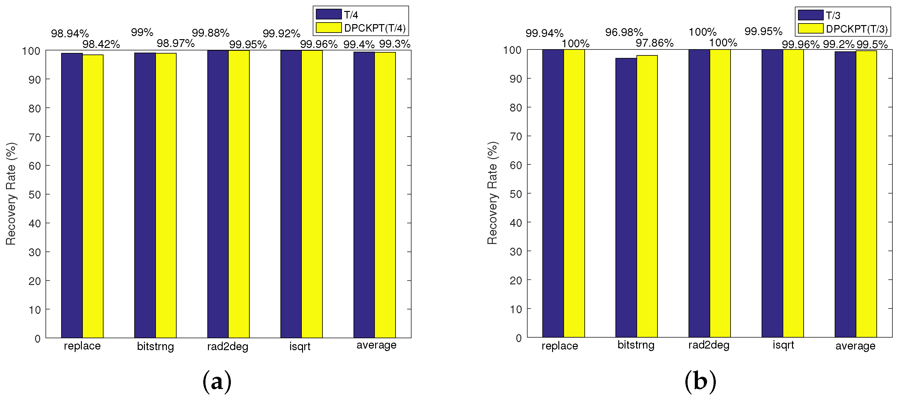
Figure 13 shows the results of the recovery rate. As shown in Figure 13a, the average recovery rate was 99.4% for the periodic checkpointing recovery approach with a checkpoint interval of T/4 and 99.3% for DLCKPT. The difference in the recovery rate between the two methods was only 0.1%, which was negligible. Figure 13b shows that the average recovery rate was 99.2% for the periodic checkpointing recovery approach with a checkpoint interval of T/3 and 99.5% for DLCKPT. The two recovery rates were almost equal. The average recovery rate of 99.4% and 99.2% was 99.3% for the periodic checkpointing recovery approach, and that of 99.3% and 99.5% was 99.4% for DLCKPT, indicating a small difference between the two methods. The reason that the recovery rate is not 100% is that the data saved by the checkpoints is not always correct. In the following, we use the program segment in Figure 8 as an example to provide an explanation. We assume a soft error occurs when the statement in line 1 is executed; thus, the value of the variable b i z is −2 (an incorrect value). After the execution of the statement in line 1, the assertion in line 2 is executed. The assertion represents a detector. It detects whether a soft error has occurred in the variable b y z e . In this case, the assertion is not false, indicating no errors have been detected. The for loop in line 3 and line 4 is executed subsequently. We assume that a checkpoint called c 1 is generated by the checkpointing strategy after executing the for loop.
It should be noted that the value of the variable b i z saved by c 1 is incorrect. Next, the assertion in line 5 is executed. The assertion is false because b i z is not greater than or equal to −1, i.e., an error in the variable b i z has been detected. In this case, the checkpoint strategy rolls the program back to c 1 , and the program continues running from c 1 . Because the value of b i z saved by c 1 is incorrect, the program rolls back to c 1 once again when it executes the statement in line 5 again; thus, the recovery fails.
Although the recovery rate was not 100%, it was higher than 99%, satisfying the needs of most users. The recovery rate is related to the data stored in a checkpoint. The more accurate the data stored in the checkpoint, the higher the recovery rate is. The reason for our accuracy values is that most of the data stored in a checkpoint by BLCR was correct. In this study, we focused on optimizing the time overhead, not the recovery rate. We will focus on the latter in a future study by storing more accurate data in a checkpoint.

6.2.4. Space Overhead

The results of the space overhead are presented in Figure 14. As shown in Figure 14a, the average space overhead was 44.5% for the periodic checkpointing recovery approach with a checkpoint interval of T/4 and 33.2% for DLCKPT. Figure 14b shows that the average space overhead was 44.2% for the periodic checkpointing recovery approach with a checkpoint interval of T/3 and 36% for DLCKPT. The average space overhead was 44.4% (44.5% and 44.2%) for the periodic checkpointing recovery approach and 34.6% (33.2% and 36%) for DLCKPT. Figure 14a,b also show that the space overhead of bitstrng was lower for the periodic checkpointing recovery approach than for DLCKPT. The reason is that DLCKPT did not consider the space overhead when redeploying checkpoints. Thus, the space overhead differed for the different programs. Regardless, the experimental results show that the averaged space overhead across the four programs was slightly lower for DLCKPT than for the periodic checkpointing recovery approach. Figure 14a,b indicate that the space overheads of the two approaches were not very low. The lowest space overhead was 39.3% for the periodic checkpointing recovery approach and 23.7% for DLCKPT. The reason is that the space overhead is related to the data stored in a checkpoint. The lower the data volume of the checkpoint, the lower the space overhead is. Many intermediate data points were generated during the execution of the programs and stored in a checkpoint by the BLCR, resulting in a large checkpointing data volume. The optimization of the space overhead will be considered in a future study.

7. Conclusions and Future Work

In this paper, we propose the DLCKPT approach, which deploys checkpoints by considering detector locations to reduce the time overhead. This method first deploys initial checkpoints and generates program segments based on the periodic checkpointing recovery approach. It handles each program segment sequentially and determines whether the checkpoints of the program segment are adequate or redundant by evaluating the change in the time overhead when additional checkpoints are inserted or deleted. In particular, the detector locations are considered in the evaluation of the time overhead.
An experiment was conducted to evaluate the DLCKPT. The result demonstrated that the DLCKPT had a lower time overhead than the periodic checkpointing recovery approach. The recovery rates were similar for the two methods, and the average space overhead was slightly lower for DLCKPT than for the periodic checkpointing recovery approach.
In a future study, we will optimize the space overhead and recovery rate of the DLCKPT by determining which data should be stored in the checkpoints. In this study, the checkpoints were only inserted into the middle of the program segments to determine the checkpoints’ adequacy. Other locations of the program segments will be considered to reduce the time overhead. In addition, multiple program segments rather than only two program segments will be merged into one program segment to determine the checkpoints’ redundancies.

Author Contributions

Conceptualization, N.Y. and Y.W.; investigation, N.Y. and Y.W.; methodology, N.Y. and Y.W.; software, N.Y.; supervision, Y.W.; validation, N.Y.; writing—original draft preparation, N.Y.; writing—review and editing, Y.W.; funding acquisition, Y.W. All authors have read and agreed to the published version of the manuscript.

Funding

This research was funded by the National Pre-research Project, China with grant No. WDZC20215250117.

Conflicts of Interest

The authors declare no conflict of interest.

References

  1. Gupta, N.; Shah, A.P.; Kumar, R.S.; Gupta, T.; Khan, S.; Vishvakarma, S.K. On-Chip Adaptive VDD Scaled Architecture of Reliable SRAM Cell with Improved Soft Error Tolerance. IEEE Trans. Device Mater. Reliab. 2020, 20, 694–705. [Google Scholar] [CrossRef]
  2. Hashimoto, M.; Liao, W. Soft Error and Its Countermeasures in Terrestrial Environment. In Proceedings of the 25th Asia and South Pacific Design Automation Conference (ASP-DAC), Beijing, China, 13–16 January 2020; pp. 617–622. [Google Scholar]
  3. Binder, D.; Smith, E.C.; Holman, A.B. Satellite Anomalies from Galactic Cosmic Rays. IEEE Trans. Nucl. Sci. 1975, 22, 2675–2680. [Google Scholar] [CrossRef]
  4. Ma, J.C.; Yu, D.Y.; Wang, Y.; Cai, Z.B.; Zhang, Q.X.; Hu, C. Detecting Silent Data Corruptions in Aerospace-Based Computing Using Program Invariants. Int. J. Aerosp. Eng. 2016, 2016, 1–10. [Google Scholar] [CrossRef]
  5. Tan, C.Y.; Li, Y.; Cheng, X.; Han, J.; Zeng, X.Y. General Efficient TMR for Combinational Circuit Hardening Against Soft Errors and Improved Multi-Objective Optimization Framework. IEEE Trans. Circuits Syst. 2021, 68, 3044–3057. [Google Scholar] [CrossRef]
  6. Kiani, V.; Reviriego, P. Improving Instruction TLB Reliability with Efficient Multi-bit Soft Error Protection. Microelectron. Reliab. 2019, 93, 29–38. [Google Scholar] [CrossRef]
  7. Keller, A.M.; Wirthlin, M.J. Partial TMR for Improving the Soft Error Reliability of SRAM-Based FPGA Designs. IEEE Trans. Nucl. Sci. 2021, 68, 1023–1031. [Google Scholar] [CrossRef]
  8. Didehban, M.; Lokam, S.R.D.; Shrivastave, A. InCheck: An In-application Recovery Scheme for Soft Errors. In Proceedings of the 54th ACM/EDAC/IEEE Design Automation Conference, Austin, TX, USA, 18–22 June 2017; pp. 1–6. [Google Scholar]
  9. Ma, J.C.; Duan, Z.T.; Tang, L. GATPS: An Attention-based Graph Neural Network for Predicting SDC-causing Instructions. In Proceedings of the 39th VLSI Test Symposium, San Diego, CA, USA, 25–28 April 2021; pp. 1–6. [Google Scholar]
  10. Yang, N.; Wang, Y.F. Radish: Enhancing Silent Data Corruption Detection for Aerospace-Based Computing. Electronics 2021, 10, 61. [Google Scholar] [CrossRef]
  11. Benacchio, T.; Bonaventura, L.; Altenbernd, M.; Cantwell, C.D.; Düben, P.D.; Gillard, M.; Giraud, L.; Göddeke, D.; Raffin, E.; Teranishi, K.; et al. Resilience and Fault Tolerance in High-Performance Computing for Numerical Weather and Climate Prediction. Int. J. High Perform. Comput. Appl. 2021, 35, 285–311. [Google Scholar] [CrossRef]
  12. Didehban, M.; Shrivastava, A. A Compiler Technique for Processor-Wide Protection From Soft Errors in Multithreaded Environments. IEEE Trans. Reliab. 2018, 67, 249–263. [Google Scholar] [CrossRef]
  13. Reis, G.A.; Chang, J.; August, D.I. Automatic Instruction-Level Software-Only Recovery. IEEE Micro 2007, 67, 36–47. [Google Scholar] [CrossRef]
  14. Guo, Y.M.; Wu, H.; Chai, W.X.; Ma, J.Z.; Zhou, G.C. Integrity Checking based Soft Error Recovery Method for DSP. In Proceedings of the Prognostics and System Health Management Conference, Chengdu, China, 19–21 October 2016; pp. 1–4. [Google Scholar]
  15. Yang, N.; Wang, X.; Wang, Y.; Zhai, Q. Dependent and Heterogeneous Process Migration Based on Checkpoints. In Proceedings of the IEEE International Conference on Parallel and Distributed Processing with Applications, Big Data and Cloud Computing, Exeter, UK, 17–19 December 2020; pp. 84–92. [Google Scholar]
  16. Restrepo-Calle, F.; Martĺnez-Álvarez, A.; Cuenca-Asensi, S.; Jimeno-Morenilla, A. Selective SWIFT-R: A Flexible Software-Based Technique for Soft Error Mitigation in Low-Cost Embedded Systems. J. Electron. Test. 2013, 29, 825–838. [Google Scholar] [CrossRef]
  17. Didehban, M.; Shrivastava, A.; Lokam, S.R.D. NEMESIS: A Software Approach for Computing in Present of Soft Errors. In Proceedings of the IEEE International Conference on Computer-Aided Design, Irvine, CA, USA, 13–16 November 2017; pp. 297–304. [Google Scholar]
  18. Amrizal, M.A.; Uno, A.; Sato, N.Y.; Takizawa, H.; Kobayashi, H. Energy-Performance Modeling of Speculative Checkpointing for Exascale Systems. IEICE Trans. Inf. Syst. 2017, 12, 2749–2760. [Google Scholar] [CrossRef]
  19. Quezada-Sarmiento, P.A.; Elorriaga, J.A.; Arruarte, A.; Jumbo-Flores, L.A. Used of Web Scraping on Knowledge Representation Model for Bodies of Knowledge as a Tool to Development Curriculum. In Trends and Applications in Information Systems and Techinologies; Springer: Berlin, Germany, 2021; Volume 2, pp. 611–620. [Google Scholar]
  20. Ma, J.C.; Duan, Z.T.; Tang, L. Deep Soft Error Propagation Modeling Using Graph Attention Network. J. Electron. Test. 2022, 38, 303–319. [Google Scholar] [CrossRef]
  21. Sharanyan, S.; Kumar, A. An optimized Checkpointing Based Learning Algorithm for Single Event Upsets. In Proceedings of the IEEE International Conference on Annual Computer Software and Applications, Seoul, Republic of Korea, 19–23 July 2013; pp. 395–400. [Google Scholar]
  22. Subasi, O.; Krishnamoorthy, S. On the Theory of Speculative Checkpointing: Time and Energy Considerations. In Proceedings of the ACM International Conference on Computing Frontiers, Ischia, Italy, 8–10 May 2018; pp. 165–172. [Google Scholar]
  23. Sangchoolie, B.; Pattabiraman, K.; Karlsson, J. An Empirical Study of the Impact of Single and Multiple Bit-Flip Errors in Programs. IEEE Trans. Dependable Secur. Comput. 2020, 2020, 1–18. [Google Scholar] [CrossRef]
  24. Yang, N.; Wang, Y. Predicting the Silent Data Corruption Vulnerability of Instructions in Programs. In Proceedings of the IEEE International Conference on Parallel and Distributed Systems, Tianjin, China, 4–6 December 2019; pp. 862–869. [Google Scholar]
  25. Li, G.P.; Pattabiraman, K.; Hari, S.K.S.; Sullivan, M.; Tsai, T. Modeling Soft-Error Propagation in Programs. In Proceedings of the IEEE International Conference on Dependable Systems and Networks, Luxembourg, 25–28 June 2018; pp. 27–38. [Google Scholar]
  26. Ma, J.C.; Wang, Y. Characterization of Stack Behavior under Soft Errors. In Proceedings of the Design, Automation & Test in Europe Conference & Exhibition, Lausanne, Switzerland, 27–31 March 2017; pp. 1534–1539. [Google Scholar]
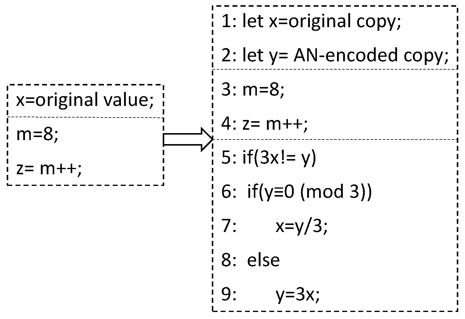
Figure 1. A pseudo-code of duplication-based recovery.
Electronics 12 00805 g001
Figure 2. An example of a shell script describing a recovery.
Electronics 12 00805 g002
Figure 3. An example of checkpoints.
Electronics 12 00805 g003
Figure 4. An example of SWIFT-R.
Electronics 12 00805 g004
Figure 5. The time overhead of a program.
Electronics 12 00805 g005
Figure 6. The overview of the DLCKPT approach.
Electronics 12 00805 g006
Figure 7. The division of program segments.
Electronics 12 00805 g007
Figure 8. An example of a program segment.
Electronics 12 00805 g008
Figure 9. The time overhead of a program segment.
Electronics 12 00805 g009
Figure 10. An example of adding a checkpoint.
Electronics 12 00805 g010
Figure 11. An example of deleting a checkpoint.
Electronics 12 00805 g011
Figure 12. The pseudo-code of the procedure of checkpoint and recovery operations.
Electronics 12 00805 g012
Figure 13. (a) The result of the recovery rate of the periodic checkpointing recovery approach with a checkpoint interval of T/4 and that of DLCKPT that redeploys the checkpoints of checkpoint interval of T/4. (b) The result of the recovery rate of the periodic checkpointing recovery approach with a checkpoint interval of T/3 and that of DLCKPT that redeploys the checkpoints of checkpoint interval of T/3.
Electronics 12 00805 g013
Figure 14. (a) The result of the space overhead of the periodic checkpointing recovery approach with a checkpoint interval of T/4 and that of DLCKPT that redeploys the checkpoints of checkpoint interval of T/4. (b) The result of the space overhead of the periodic checkpointing recovery approach with a checkpoint interval of T/3 and that of DLCKPT that redeploys the checkpoints of checkpoint interval of T/3.
Electronics 12 00805 g014
Table 1. Meanings of terms.
NameMeaning
Checkpointing timeThe time required to preserve a program’s running state.
Recovery time of a historical stateThe time required to restore the data of the latest checkpoint.
Recovery time of a current stateThe time required to execute a program from the latest checkpoint
to the place where an error is reported by a detector.
Recovery timeThe time required to recover the historical state and current state.
Fault tolerance timeThe checkpointing time and recovery time.
Overall program execution timeThe original program execution time and fault tolerance time.
Table 2. The results of e p .
ProgramsT/4T/3
replace22.1%14.1%
bitstrng4%8%
rad2deg10%10%
isqrt22.3%13.5%
average15%11.4%
Table 3. The results of f p .
ProgramsT/4T/3
replace25.6%15.3%
bitstrng3%2%
rad2deg11%12%
isqrt23.2%14.5%
average16%11%
Disclaimer/Publisher’s Note: The statements, opinions and data contained in all publications are solely those of the individual author(s) and contributor(s) and not of MDPI and/or the editor(s). MDPI and/or the editor(s) disclaim responsibility for any injury to people or property resulting from any ideas, methods, instructions or products referred to in the content.