Abstract
Electric vehicles (EVs) integrate two main power electronics systems, namely, the battery charging system and the traction system. In this study, we aimed to complement and deepen the study of the latter, more specifically, focusing on a traction system based on a synchronous reluctance permanent magnet (SRPM) machine, since this is an emerging electric machine in the EV paradigm. The developed prototype integrates bidirectional ac-dc and dc-dc converters, allowing for regenerative braking, and the SRPM machine is controlled using a maximum torque per ampere (MTPA) algorithm. Computer simulations and the experimental results for the traction system are presented in this paper. The dynamic characteristics of the SRPM machine proved to be relevant for EV applications, with effective results obtained during load and speed changes. The effective behavior of the SRPM machine was partially rooted in the use of the MTPA algorithm, which has proven itself to be an effective algorithm for the electric machines of EVs.
1. Introduction
The increase in energy needs had led to an increase in the scarcity of resources such as fossil fuels—resources that are primarily responsible for environmental pollution, contributing to the greenhouse effect. Electric vehicles (EVs) reduce the dependence on fossil fuels by converting mobility from a landscape heavily powered by fossil fuels to electric energy, which, despite being partially derived from fossil fuels, is converted more efficiently than in vehicles with internal combustion engines. Since EVs are produced en masse, it is important to diversify the technologies available for powertrains in order to mitigate material shortages such as the drastic spike observed in 2011 in the prices of rare-earth magnets, such as neodymium [1]. That event sparked an increase in the investigation of alternative solutions for the electric machines of EVs, with synchronous reluctance permanent magnet (SRPM) machines being one of them [2,3].
The SRPM machine consists of the combination of a synchronous reluctance machine (SynRM) with a permanent magnet synchronous machine (PMSM), either by adding permanent magnets to the former or by adding salience to the latter. SRPM machines are present in EVs such as the Tesla Model 3, allied with an induction machine in the dual-motor versions, with the intention of matching the performance of the latter with the efficiency of the former [4]. EVs such as the BMW i3 and i8 and the Jaguar I-Pace contain SRPM machines even though they are advertised as PMSM machines, because they have slotted rotors, introducing salience to the machine [5]. This topology of electric machines allows two ways of generating torque, namely, through magnetic reluctance and through permanent magnets. The magnetic reluctance can be compared to the resistance in an electric circuit, meaning that it corresponds to the resistance to a magnetic field. The torque produced via magnetic reluctance is achieved due to the structural composition of the rotor. The rotor is slotted in a way that creates a sequence of lower and higher reluctance around it. So, when the stator is producing a magnetic field, the rotor will be subjected to torque in order to align itself with the magnetic field at the path of least reluctance. The presence of a rotating magnetic field in the stator that is synchronized with the rotor will continuously produce torque. The torque produced via the permanent magnets is based on the same principle. The magnetic field produced by the permanent magnets reacts with the magnetic field produced by the stator windings, subjecting the rotor to torque in order to align both magnetic fields. Similarly to the reluctance torque, the presence of a rotating magnetic field in the stator that is synchronized with the rotor will continuously produce torque [6,7,8,9,10].
The rest of the paper is organized as follows. Section 2 presents the SRPM machine implemented in the prototype, along with the control algorithm and converter topologies used. Section 3 presents the simulation results of the traction system prototype. Section 4 presents the developed prototype with the respective experimental results. Lastly, Section 5 presents the conclusions of this paper.
2. Synchronous Reluctance Permanent Magnet Machine
The comparison of permanent magnet-assisted synchronous reluctance machines, or SRPM machines, with other topologies such as PMSM, SynRM and induction machines (IM), has been extensively investigated in the last decade [11,12]. In Table 1, a comparison between IM, SynRM and SRPM machines is presented, with the data from [13]. The improvements of SRPM machines compared to SynRM machines are significant, considering the increase in efficiency and torque and lower torque ripple, with a reduced increase in cost. The SRPM machine, in comparison to a PMSM machines, has slightly lower efficiency and at lower speeds produces less torque, but it produces more torque at higher speeds, resulting in a higher power output and a wider operating range, which is suitable for EVs.

Table 1.
Comparison between IM, SynRM and SRPM machines [13].
The SRPM machine implemented in the prototype in this study was the model SRPM205M8XO75 from the manufacturer MC Motor and its respective nominal characteristics are presented in Table 2. The SRPM machine has a salience that equals three, meaning that the inductance along the q-axis (Lq) is three times the inductance along the d-axis (Ld). The d-axis corresponds to the axis of least reluctance between the stator and the rotor and the q-axis to the one with the most reluctance, in other words, the d-axis is associated with the main magnetic flux that flows through the ferromagnetic material in the rotor and the q-axis is associated with the magnetic flux that flows through the permanent magnets and the slots. In the case of Ld = Lq, there is no salience, just as in a PMSM machine, and regarding SynRM, Ld << Lq, meaning that the salience reaches high values, being infinite in an ideal scenario.
Table 2.
Nominal characteristics of the SRPM205M8XO75 electric machine.
Since torque is directly related to the current in the stator windings of an electric machine, extracting the highest possible torque for a given current ensures the highest efficiency. For that reason, the SRPM machine was controlled by means of a maximum torque per ampere (MTPA) algorithm with field-oriented control (FOC) as its basis.
Through the implementation of Park’s transform [14,15,16], it is possible to convert the abc coordinate system to the dq coordinate system, which consists of having a rotating synchronous axis system instead of a stationary one, converting sine-wave variables to constant ones that behave similarly to dc variables, allowing a control mechanism similar to that of dc machines, which is simpler.
Applying Park’s transform to the stator windings’ currents (ia, ib and ic) resulted in id, iq and i0, where id is the d-axis current, which corresponds to the magnetizing current, and iq is the q-axis current, which is associated with torque generation. On the other hand, i0 can be disregarded since the electric machine has no neutral wire, as it is a three-wire three-phase system, and there are no zero-sequence components in the system. The torque of a SRPM machine can be given by [17]:
where p is the number of pole pairs; λpm is the permanent magnet’s flux linkage; and Ld and Lq are the d-axis and q-axis inductances, respectively. The MTPA algorithm optimizes torque generation by acting on the current angle between id and iq, varying from π/4 to π/2 depending on the overall current produced.
The reference value for iq is calculated based on the torque or speed required by the application, either by the accelerator pedal or cruise control, respectively. Then, in order to achieve MTPA, id is calculated according to the following expression [18,19]:
The control is established through an iq reference value provided by the accelerator pedal signal, since it is directly proportional to the torque, and in the case of speed control, such as cruise control, an additional control loop is integrated, namely, a proportional-integral (PI) controller that generates a reference value for iq based on the rotational speed of the SRPM machine. Once the reference values id and iq are calculated, each one is controlled via individual PI controllers and then the inverse Park transform is applied to convert the variables for pulse-width modulation (PWM) signal generation to actuate the bidirectional ac-dc converter. A control block diagram is presented in Figure 1 to aid in the visualization of the control mechanism.
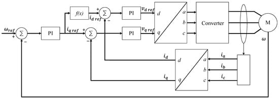
Figure 1.
Control block diagram illustrating the maximum torque per ampere (MTPA) algorithm.
The traction system that acts an interface between the batteries and the SRPM machine consists of an ac-dc and dc-dc converters sharing a dc-link, the ac-dc being a three-phase three-leg bidirectional converter with six insulated-gate bipolar transistors (IGBTs), and the dc-dc being a three-phase interleaved bidirectional buck-boost converter with six IGBTs, which means that both converters were similar in design, as can be seen in Figure 2.
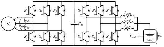
Figure 2.
Schematic illustration of the traction system.
3. Simulation Results
In this section we present the traction system simulation results. With the use of PSIM software from PowerSim, the whole system was simulated: both the ac-dc and the dc-dc converters, the SRPM machine and the control algorithms, from the signal acquisition step to the MTPA algorithm. A detailed schematic of the PSIM system, including the power converters and the control system, is presented in Figure 3.
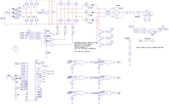
Figure 3.
PSIM simulation schematic.
Figure 4 presents the simulation results obtained for the SRPM machine at nominal speed, coupled with a load of 50 Nm, showing the applied voltages and currents in the stator windings in both the abc and dq coordinate systems. More specifically, in Figure 4a, the electric machine is rotating in the positive direction, which can be confirmed by the sequence of phases being abc. In the case of Figure 4b, the sequence of phases becomes acb, representing a negative direction of rotation, resulting in inverted values for both iq and vq, as expected, validating Park’s transform.
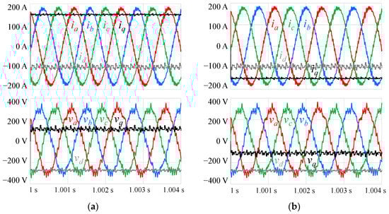
Figure 4.
Simulation results of the stator winding voltages (va, vb, vc, vd, vq) and currents (ia, ib, ic, id, iq), applying Park’s transform with the electric machine operating as a motor at nominal speed (12 krpm), coupled with a 50 Nm load, rotating in the directions conventionalized as (a) positive and (b) negative.
Similarly to the results presented in Figure 4, Figure 5 depicts the SRPM machine operating as a generator through a “negative load” of equal magnitude, with a load of −50 Nm. In relation to the previous results, the currents shifted 180° in this phase, which can be confirmed by the inversion of the iq values, and regarding the voltage, this resulted in an inversion of the vd values.
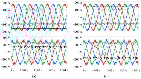
Figure 5.
Simulation results of the stator windings voltages (va, vb, vc, vd, vq) and currents (ia, ib, ic, id, iq), applying Park’s transform with the electric machine operating as a generator at nominal speed (12 krpm), coupled with a −50 Nm load, rotating in the directions conventionalized as (a) positive and (b) negative.
In Figure 6, a more dynamic result can be observed, this being the acceleration of the SRPM machine from a stopped position, having a reference speed of 12 krpm. In this simulation, iq was limited to 180 A, allowing for a maximum torque (Tm) of roughly 70 Nm, which was higher than that of the SRPM machine implemented in the prototype because the simulation model of the machine did not account for magnetic saturation. The stator windings’ currents can be seen in both the abc and dq coordinate systems, allowing for the visualization of the increase in frequency with the increase in speed.
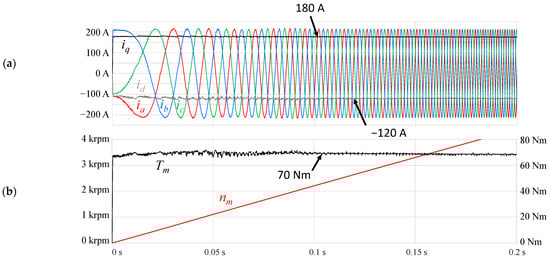
Figure 6.
Simulation results of the control algorithm coupled with a 10 Nm load during start-up, representing the (a) stator windings’ currents (ia, ib, ic, id, iq); (b) torque (Tm) and speed (nm) of the SRPM machine.
In Figure 7, the dc link and battery current can be observed in the event of an acceleration from a stop to nominal speed, this time without a load. As can be seen in the figure, with the increase in speed and subsequently in power, the current in the battery increases linearly in order to provide the power necessary for the electric machine. The dc-link reference value (vdc) was set to 800 V and was controlled via a PI controller. During acceleration, the load on the traction system maintained the vdc value around 795 V, and after 0.48 s the nominal speed was reached, creating a sudden change in load that translated into a voltage overshoot of 1.1% in vdc and a measly 0.467% overshoot in speed (nm), which would be higher if there were higher loads coupled with the electric machine, increasing the inertia of the mechanical system.
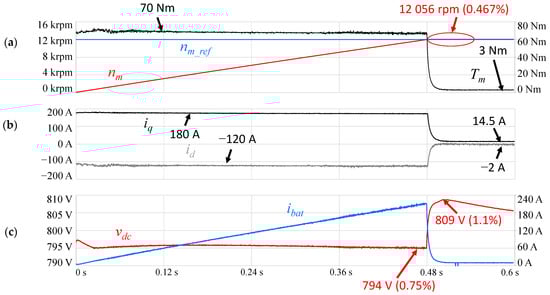
Figure 7.
Simulation results of the traction system accelerating from a stop to nominal speed without a load, representing (a) the torque (Tm), speed (nm) and reference speed (nm_ref) of the SRPM machine; (b) the stator windings’ currents (id, iq); (c) the dc link voltage (vdc) and the battery current (ibat).
Figure 8 presents four different load states observed when keeping the reference speed constant at its nominal value of 12 krpm. At start-up there was no load, as can be inferred from the low values of current, torque and power. Then, at 0.4 s the load was increased to 30 Nm, resulting in an increase in current and, subsequently, torque, as well as undershoots in speed and vdc of 0.32% and 0.63%, respectively. The resulting torque in the cruise state was around 34 Nm and the power was around 42.9 kW. At 0.45 s, the load decreased to −30 Nm, resulting in a change in the operation mode from a motor to a generator, with an inversion in current and torque. This change caused overshoots in speed and vdc of 0.59% and 1.1%, respectively. The resulting torque in the cruise state was around −29 Nm and the power was around −36.6 kW. Even when the value of the load was symmetrical, the losses in electrical and mechanical systems translated into lower torque and power values when operating as a generator in comparison to operating as a motor. Finally, at 0.5 s the load was increased to 10 Nm, inverting the operation mode from a generator to a motor. The behavior is similar to the observations at 0.4 s, where slight undershoots in terms of speed and vdc of 0.32% and 0.63%, respectively, were observed. The resulting torque in the cruise state was around 14 Nm and the power was around 18.1 kW.
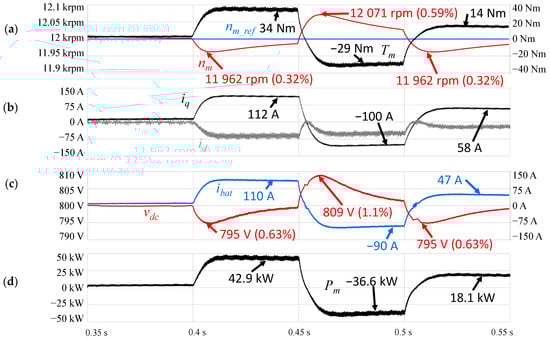
Figure 8.
Simulation results of the traction system, varying the load at nominal speed, representing (a) the torque (Tm), speed (nm) and reference speed (nm_ref) of the SRPM machine; (b) the stator windings’ currents (id, iq); (c) dc-link voltage (vdc) and battery current (ibat); (d) the power (Pm) of the SRPM machine.
As opposed to the load-changing results shown in Figure 8, in Figure 9 the simulation results of speed variations with a constant load of 20 Nm are presented. At the start, the electric machine was operating at 6 krpm, resulting in torque and power values of 21.4 Nm and 13.5 kW, respectively. At 0.4 s the reference speed was decreased to 2 krpm, which resulted in deceleration that triggered regenerative braking, maxing out iq at −180 A and overshooting vdc by 1.38%. It took about 0.116 s to reach the new reference speed, undershooting by 5.2%. When in the cruise state, the torque was similar, at about 21.1 Nm, and the power was roughly a third of the previous value, at 4.2 kW, which was expected since it was operating at a third of the previous speed. At 0.6 s the reference speed was increased to 4 krpm, resulting in an acceleration that maxed out iq at 180 A and undershot vdc by 0.63%. It took about 0.113 s to reach the new reference speed, overshooting by 0.8%. When in the cruise state, the torque was similar, at about 20.8 Nm, and the power was roughly twice the previous power, at 8.8 kW, which was expected since it was operating at double the previous speed.
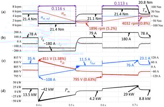
Figure 9.
Simulation results of the traction system when varying the speed, coupled with a 20 Nm load, representing (a) the torque (Tm), speed (nm) and reference speed (nm_ref) of the SRPM machine; (b) the stator windings’ currents (id, iq); (c) dc link voltage (vdc) and battery current (ibat); (d) the power (Pm) of the SRPM machine.
4. Experimental Results
This section presents the hardware used, describing the most relevant aspects of the traction system prototype, and the experimental results that were obtained with the prototype. An overview of the prototype can be seen in Figure 10.
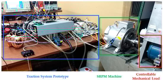
Figure 10.
Traction system prototype workbench overview.
In Figure 11, the traction prototype can be seen in more detail. More specifically, Figure 11a depicts the control printed circuit board (PCB) that housed the TMS320F28379D microcontroller from Texas Instruments, along with the signal conditioning and protection mechanisms and the AD2S1205 resolver-to-digital converter with its respective circuits. Furthermore, on top of the aluminium case that covered the power converters, was a PCB sensor that integrated Si8920BC-IP isolated amplifiers from Silicon Labs for measuring currents and voltages, either coupled with shunt resistors or voltage dividers, respectively. On the left are the dc-dc converter’s inductors, which were made in-house with Micrometals OE-520026-2 iron powder cores, and which had an inductance value of 140 μH at 250 A. In Figure 11b, it is possible to observe what lies below the aluminium case, with two structurally similar converters sharing a dc link, the left one being the dc-dc converter and the one on the right being the ac-dc converter. The dc link had three types of capacitors, six 420 µF B25620B1427A101 capacitors from TDK, twelve 25 µF C4AQQBW5250A3OJ capacitors from KEMET and, lastly, twelve 22 nF A72SQ2220AA00J capacitors, also from KEMET, all in parallel, resulting in a total capacitance of 2820 µF. Each switch of the power converter topology was implemented with four IKW40N120H3 IGBTs from Infineon Technologies in parallel, and for the respective antiparallel diodes, four SiC-based Schottky C4D08120E diodes were used due to their positive temperature coefficients. To protect the semiconductors, transient voltage suppressors were implemented, using two 1.5KE600A devices from Littelfuse in series in order to withstand 1024 V, which is higher than the nominal dc-link voltage but lower than the 1200 V maximum allowed by the semiconductors. As for gate drivers, Infineon Technologies model 1EDI60N12AF systems were used per switch, in other words, per set of four parallel IGBTs. To cool the power converter’s semiconductors, a water-cooling system was implemented through the use of two 416601U00000G cold plates from Aavid, with one per converter.
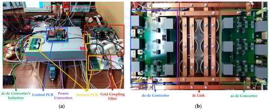
Figure 11.
Traction system prototype: (a) external view; (b) internal view of the power converters.
The test results of the prototype were obtained with the dc link being fed from the power grid with transformers in a star-delta configuration, starting with a 230/75 transformer turn ratio that resulted in a dc-link voltage of 190 V. The dc-dc converter operated during regenerative braking instances.
The results of the traction system operating at a speed of 1500 rpm without a load can be seen in Figure 12, which illustrates the stator windings currents, torque and speed. The torque and speed values were supplied by the digital-to-analog (DAC) channels available on the microcontroller, which were configured to ranges of ±20 Nm and ±3000 rpm, respectively. The current sensors had a 10.86 mV/A ratio, corresponding to a peak of 11 A in this case. The torque was approximately 2 Nm, which was expected, considering the rolling resistance in the bearings and the rotor. The frequency of the currents was 100 Hz, which was an eighth of the nominal value, and which was expected considering that it is also rotated at an eighth of the nominal speed.
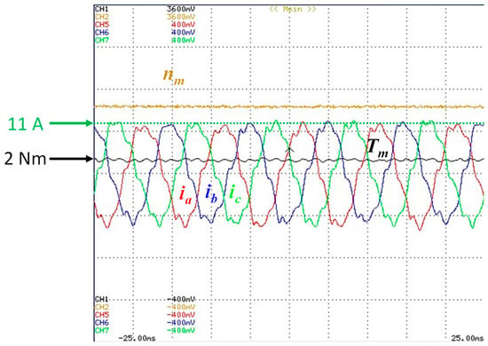
Figure 12.
Experimental results obtained for the traction system operating at a constant speed (1500 rpm) without a load: the torque (Tm) and speed (nm) of the SRPM machine; the stator windings’ currents (ia, ib, ic).
After validating the system with a lower voltage, the dc link was increased to 250 V by changing the transformer turn ratio to 230/100. The speed value range of the DAC was increased to ±6000 rpm. After these adjustments, the reference speed and load were increased to 2000 rpm and 8 Nm, respectively, as can be seen in Figure 13. The dc-link voltage was added to the measurements, and an average of 250 V was observed. The current had a frequency of 133 Hz and peaked at approximately 37 A. The torque was approximately 8.6 Nm, which was slightly higher than the load because of the rolling resistance, as observed in the previous results.
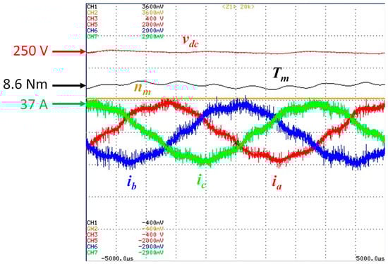
Figure 13.
Experimental results of the traction system operating at a constant speed (2000 rpm) with an 8 Nm load: the torque (Tm) and speed (nm) of the SRPM machine; dc-link voltage (vdc); stator windings’ currents (ia, ib, ic).
In the next iteration, the load was removed and the reference speed was increased to 4000 rpm, as can be seen in Figure 14. The torque was approximately 4.1 Nm since the increase in speed resulted in an increase in the rolling resistance effect. The currents peaked at 19 A and doubled in frequency, which was expected.
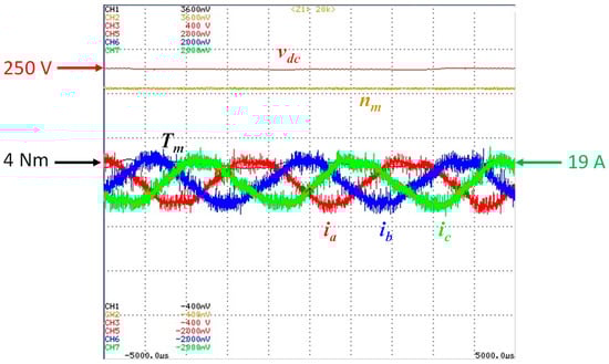
Figure 14.
Experimental results of the traction system operating at a constant speed (4000 rpm) without a load: the torque (Tm) and speed (nm) of the SRPM machine; dc-link voltage (vdc); stator windings’ currents (ia, ib, ic).
Once again, the dc-link voltage was increased by changing the transformer turns ratio to 230/150, with the voltage varying from 367 V to 400 V, depending on the load. As can be seen in Figure 15, the dc-link voltage was around 370 V when rotating at 2000 rpm with a 12 Nm load. The currents peaked at 55 A and the torque produced was 13.5 Nm, as expected.
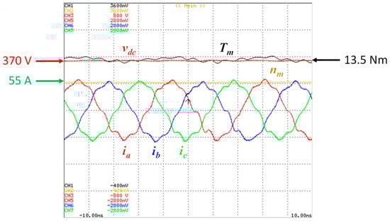
Figure 15.
Experimental results of the traction system operating at a constant speed (2000 rpm) with a 12 Nm load: the torque (Tm) and speed (nm) of the SRPM machine; dc-link voltage (vdc); stator windings’ currents (ia, ib, ic).
To achieve higher speeds, the load was removed once again, and the reference speed was increased to 6000 rpm, as can be seen in Figure 16. The dc-link voltage was approximately 380 V. The frequency of the currents was 400 Hz, which was half of the nominal value, as was observed with the speed. The torque produced was 5.1 Nm, representing the highest results obtained without a load.
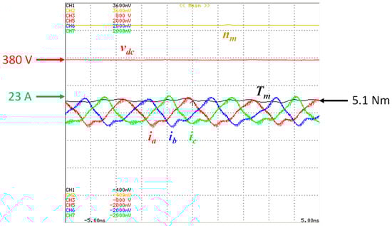
Figure 16.
Experimental results of the traction system operating at a constant speed (6000 rpm) without a load: the torque (Tm) and speed (nm) of the SRPM machine; dc-link voltage (vdc); stator windings’ currents (ia, ib, ic).
In order to analyze the dynamic behavior of the SRPM machine and the MTPA control algorithm, load and speed changes were analyzed, starting with load changes. The dc-link voltage was configured to 190 V and the speed value range was decreased to ±3000 rpm, similarly to the first reported results (Figure 12). In Figure 17a, the response of the SRPM machine rotating at 1000 rpm to an increase in load is depicted. Initially, the torque produced was 1 Nm and when the load was increased to 4 Nm, this resulted in a torque of 4.8 Nm, which was enough to keep the 4 Nm load and rotor rotating at 1000 rpm. During the load transition, the SRPM machine experienced a slight deceleration of approximately 20 rpm, corresponding to 2% of the reference speed. The result illustrated in Figure 17b complements the previous one, representing the transition from a 4 Nm load to no load. During the load transition, the SRPM machine underwent a slight acceleration of approximately 40 rpm, corresponding to 4%. Note that the load changes were performed manually, which resulted in slightly different response times between both cases.
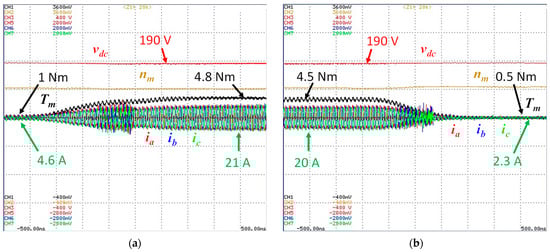
Figure 17.
Experimental results of the traction system operating at 1000 rpm: the torque (Tm) and speed (nm) of the SRPM machine; dc-link voltage (vdc); and stator windings’ currents (ia, ib, ic) when varying the load from (a) 0 Nm to 4 Nm and (b) 4 Nm to 0 Nm.
After analyzing the load changes, the behavior of the system in response to speed changes was analyzed. In Figure 18, the transition of the SRPM machine decelerating from 1500 rpm to 1000 rpm is depicted. The load was adjusted in order for the SRPM machine to produce 2 Nm at 1500 rpm. Initially, the torque was 2 Nm and the current peaks were 9.2 A. At the instant at which the reference speed was decreased to 1000 rpm, the torque peaked at −20 Nm, which triggered regenerative braking that lasted for 0.35 s. The currents peaked at 74 A. The dc-link voltage, which was at 190 V, increased to 210 V because the regenerative braking was configured to be triggered at that voltage. For the experimental tests, the dc-dc converter was coupled to a resistor bank instead of batteries. The resistor bank was configured to 3.7 Ω, which stemmed the energy from regenerative braking. The prototype took approximately 0.2 s to reach the new reference speed, even though the system took around 0.5 s to reach the cruise state.
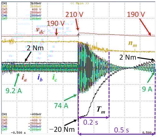
Figure 18.
Experimental results of the traction system with a 2 Nm load decelerating from 1500 rpm to 1000 rpm: the torque (Tm) and speed (nm) of the SRPM machine; dc-link voltage (vdc); stator windings’ currents (ia, ib, ic).
Figure 19 shows the performance of the speed control mechanism during a rotational direction inversion. The reference speed had an absolute value of 1000 rpm, and no load was coupled to the SRPM machine. In Figure 19a, the SRPM machine is rotating at −1000 rpm, producing approximately 0.5 Nm of torque. When the command for the inversion is applied, the dc link voltage shoots to 210 V, triggering regenerative braking. The currents peak at a value of 83 A, which corresponds to 22.5 Nm of torque. The moment that the speed reaches zero, the sequence of currents changes from acb to abc, representing the inversion to the conventionalized positive direction of rotation. It is also at the moment that the speed reaches zero that regenerative braking ceases, since the SRPM machine starts to accelerate, which also causes the dc-link voltage to achieve a minimum of 180 V. The behavior displayed in Figure 19b is identical to the previously described behavior, with the exception of starting at 1000 rpm and then inverting the rotation direction to the conventionalized negative one. Both produced 0.5 Nm in the cruise state, and both reached the same current and torque peaks. The dc-link voltage underwent virtually the same transitions. The inversion lasted approximately 1 s in both instances.
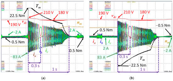
Figure 19.
Experimental results of the traction system: the torque (Tm) and speed (nm) of the SRPM machine, dc-link voltage (vdc) and stator windings’ currents (ia, ib, ic) when inverting the rotation direction without a load: (a) −1000 rpm to 1000 rpm; (b) 1000 rpm to −1000 rpm.
Figure 20 shows the behavior of the prototype when using the accelerator pedal as an input instead of the cruise control. The pedal was pressed in a linear manner. Analogously to internal combustion engine (ICE) vehicles, the accelerator pedal corresponds to a torque command. With that in mind, the accelerator pedal position was associated with iq ref, which was limited to 90 A in this instance. When the SRPM machine was stationary, the dc-link voltage was around 400 V. As expected, the currents in the stator windings were higher during the first 1.25 s of acceleration than the rest of the time, even though the value of iq ref was lower. Peak acceleration occurred around 1.3 s after the start of the acceleration, when the SRPM machine was rotating at 2000 rpm, reaching peak currents of 74 A and 20 Nm of torque. The torque slowly decreased after peak acceleration. The last moment registered was 3.75 s after the start of the acceleration, when the machine had a rotational speed of 6000 rpm.
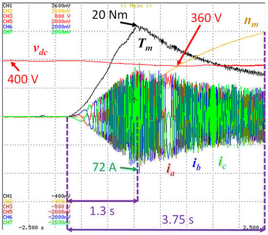
Figure 20.
Experimental results of the traction system with an accelerator pedal as the input: the torque (Tm) and speed (nm) of the SRPM machine; dc-link voltage (vdc); stator windings’ currents (ia, ib, ic).
5. Conclusions
Electric vehicles (EVs) have been experiencing incredible growth in the last decade since they have the capability of being an emissions-free means of transportation, especially in terms of localized pollution, as seen in the cities with the most heavy traffic. This paper deepens the study of synchronous reluctance permanent magnet (SRPM) machines, which are emerging in the EV paradigm, since they are cost-effective and offer compelling power density. The experimental results presented in this paper, obtained with a developed prototype, reinforce the relevance of the application of SRPM machines in the traction systems of EVs, showing effective behavior through load and speed changes in short periods of time. The maximum torque per ampere (MTPA) control algorithm also played an important role in the effectiveness of the traction system, proving to be relevant in optimizing the torque extracted from the electric machine.
Author Contributions
Conceptualization, J.D.C.S. and T.J.C.S.; validation, J.D.C.S. and T.J.C.S.; writing—original draft preparation, J.D.C.S. and T.J.C.S.; writing—review and editing, J.D.C.S., T.J.C.S., V.M. and J.L.A.; supervision, V.M. and J.L.A. All authors have read and agreed to the published version of the manuscript.
Funding
This work has been supported by FCT—Fundação para a Ciência e Tecnologia within the R&D Units Project Scope: UIDB/00319/2020.
Institutional Review Board Statement
Not applicable.
Informed Consent Statement
Not applicable.
Data Availability Statement
Not applicable.
Conflicts of Interest
The authors declare no conflict of interest.
References
- Jahns, T. Getting Rare-Earth Magnets Out of EV Traction Machines: A Review of the Many Approaches Being Pursued to Minimize or Eliminate Rare-earth Magnets from Future EV Drivetrains. IEEE Electrif. Mag. 2017, 5, 6–18. [Google Scholar] [CrossRef]
- Vagati, A.; Boazzo, B.; Guglielmi, P.; Pellegrino, G. Ferrite Assisted Synchronous Reluctance Machines: A General Approach. In Proceedings of the 2012 XXth International Conference on Electrical Machines, Marseille, France, 2–5 September 2012; pp. 1315–1321. [Google Scholar] [CrossRef]
- Boldea, I.; Tutelea, L.N.; Parsa, L.; Dorrell, D. Automotive Electric Propulsion Systems With Reduced or No Permanent Magnets: An Overview. IEEE Trans. Ind. Electron. 2014, 61, 5696–5711. [Google Scholar] [CrossRef]
- The Tesla Team. The Longest-Range Electric Vehicle Now Goes Even Farther. 2019. Available online: https://www.tesla.com/blog/longest-range-electric-vehicle-now-goes-even-farther (accessed on 28 November 2022).
- Thackwell, C.; Michaelides, A. Rare-earth Free Drive Units For Powertrain Electrification. Coiltech International Coil Winding Expo 2019. 2019. Available online: http://www.refreedrive.eu/wp-content/downloads/Coiltech_2019_ReFreeDrive_JLR.pdf (accessed on 28 November 2022).
- Ooi, S.; Morimoto, S.; Sanada, M.; Inoue, Y. Performance Evaluation of a High-Power-Density PMASynRM with Ferrite Magnets. IEEE Trans. Ind. Appl. 2013, 49, 1308–1315. [Google Scholar] [CrossRef]
- Guan, Y.; Zhu, Z.Q.; Afinowi, I.A.A.; Mipo, J.C.; Farah, P. Design of Synchronous Reluctance and Permanent Magnet Synchronous Reluctance Machines for Electric Vehicle Application. COMPEL-Int. J. Comput. Math. 2016, 35, 586–606. [Google Scholar] [CrossRef]
- Maroufian, S.S.; Pillay, P. PM Assisted Synchronous Reluctance Machine Design Using AlNiCo Magnets. In Proceedings of the 2017 IEEE International Electric Machines and Drives Conference (IEMDC), Miami, FL, USA, 21–24 May 2017; pp. 1–6. [Google Scholar] [CrossRef]
- Li, J.; Mahmoud, H.; Degano, M.; Bardalai, A.; Zhang, X.; Gerada, C. Impact on Vibration of Eccentric Permanent Magnet Assisted Synchronous Reluctance Machine. In Proceedings of the 2020 International Conference on Electrical Machines (ICEM), Gothenburg, Sweden, 23–26 August 2020; pp. 476–480. [Google Scholar] [CrossRef]
- Mohanarajah, T.; Nagrial, M.; Rizk, J.; Hellany, A. Permanent Magnet Optimization in PM Assisted Synchronous Reluctance Machines. In Proceedings of the 2018 IEEE 27th International Symposium on Industrial Electronics (ISIE), Cairns, QLD, Australia, 13–15 June 2018; pp. 1347–1351. [Google Scholar] [CrossRef]
- Nishiura, H.; Morimoto, S.; Sanada, M.; Inoue, Y. Characteristics Comparison of PMASynRM with Bonded Rare-Earth Magnets and IPMSM with Sintered Rare-Earth Magnets. In Proceedings of the 2013 IEEE 10th International Conference on Power Electronics and Drive Systems (PEDS), Kitakyushu, Japan, 22–25 April 2013; pp. 720–725. [Google Scholar] [CrossRef]
- Bottesi, O.; Alberti, L. Comparison of Small-Size Generator for High-Efficiency Hydroelectric Energy Production. In Proceedings of the 2017 IEEE International Electric Machines and Drives Conference (IEMDC), Miami, FL, USA, 21–24 May 2017; pp. 1–8. [Google Scholar] [CrossRef]
- Jia, S.; Zhang, P.; Liang, D.; Dai, M.; Liu, J. Design and Comparison of Three Different Types of IE4 Efficiency Machines. In Proceedings of the 2019 22nd International Conference on Electrical Machines and Systems (ICEMS), Harbin, China, 11–14 August 2019; pp. 1–4. [Google Scholar] [CrossRef]
- Blondel, A. Synchronous Motors and Converters: Theory and Methods of Calculation and Testing; McGraw-Hill Book Company: New York, NY, USA, 1913. [Google Scholar]
- Doherty, R.E.; Nickle, C.A. Synchronous Machines I-An Extension of Blondel’s Two-Reaction Theory. Trans. Am. Inst. Electr. Eng. 1926, XLV, 912–947. [Google Scholar] [CrossRef]
- Park, R.H. Two-Reaction Theory of Synchronous Machines Generalized Method of Analysis-Part, I. Trans. Am. Inst. Electr. Eng. 1929, 48, 716–727. [Google Scholar] [CrossRef]
- Pellegrino, G. Identification of PM Synchronous Machines Parameters for Design and Control Purposes. In The Rediscovery of Synchronous Reluctance and Ferrite Permanent Magnet Motors; Springer: Cham, Switzerland, 2016; pp. 77–107. [Google Scholar] [CrossRef]
- Chen, J.; Li, J.; Qu, R. Maximum-Torque-per-Ampere and Magnetization-State Control of a Variable-Flux Permanent Magnet Machine. IEEE Trans. Ind. Electron. 2018, 65, 1158–1169. [Google Scholar] [CrossRef]
- Li, K.; Wang, Y. Maximum Torque Per Ampere (MTPA) Control for IPMSM Drives Based on a Variable-Equivalent-Parameter MTPA Control Law. IEEE Trans. Power Electron. 2019, 34, 7092–7102. [Google Scholar] [CrossRef]
Disclaimer/Publisher’s Note: The statements, opinions and data contained in all publications are solely those of the individual author(s) and contributor(s) and not of MDPI and/or the editor(s). MDPI and/or the editor(s) disclaim responsibility for any injury to people or property resulting from any ideas, methods, instructions or products referred to in the content. |
© 2023 by the authors. Licensee MDPI, Basel, Switzerland. This article is an open access article distributed under the terms and conditions of the Creative Commons Attribution (CC BY) license (https://creativecommons.org/licenses/by/4.0/).