Abstract
This work presents a novel system model consisting of an unmanned aerial vehicle (UAV) equipped with a half/full-duplex relay (HDR/FDR) operating as a near-user in the downlink non-orthogonal multiple access (NOMA) systems. In a disaster situation, there is no direct connectivity of the active base station (BS) to the far user due to the out-of-coverage range. Therefore, UAV communication is established to aid the transmission from the same BS to the far user via the UAV. To quantify the effect, outage probability and throughput expressions in the exact and asymptotic forms were developed over the Weibull distribution (WD) fading channel. Additionally, the separation distance of the UAV from the base station is considered to quantify the effect. In particular, this paper helps to determine the optimal location of the UAV deployment from the BS at a fixed height from the ground to either maximize the far-user throughput or attain far-user throughput over different conditions of the WD fading channel. In addition, the performance results of the UAV-HDR/FDR-NOMA system are compared with those of a conventional downlink orthogonal multiple access (OMA) system. The comparison reveals that the UAV-HDR/FDR-NOMA systems outperform corresponding OMA systems in terms of outage probability and throughput over different values of the Weibull shaping index. The analytical results are then validated through numerical simulations on MATLAB.
1. Introduction
Natural disasters are globally getting more and more severe, day by day [1]. Unmanned aerial vehicles (UAVs) have been demonstrated to have the capability to rescue people in disaster regions by recent research [2]. Research on UAV-based solutions has become increasingly popular across industries and in academia. UAVs have recently shown promise in wireless communications to increase data rate and coverage due to their quick and affordable deployment, particularly in large-scale temporary events, catastrophe scenarios, and military activities [3,4,5]. In the recent literature, the deployment of UAVs in disaster management was examined exhaustively for supporting wireless communications [6,7,8,9]. Depending on the degree of interaction between the UAV and terrestrially installed wireless sensors, appropriate network designs created for each of the scenarios for geophysical, climate-related, and meteorological disasters, have been presented [10]. Ref. [11] presents the real-time deployments of UAVs to recover and maintain the network during and post-disaster scenarios. UAVs can be applied to offer air-to-ground line-of-sight (LOS) communications for ground users by acting as wireless flying relays or mobile aerial base stations (BSs) [12,13,14,15]. UAVs can replace malfunctioning ground BS in order to manage greater disaster zones effectively and efficiently [16]. The possibility of using UAVs as relay nodes improves the service coverage and throughput inside the network while providing reliable transmission to the users outside the coverage of BS [17,18]. Further, UAVs as relay provides connectivity to wireless devices under the circumstances of no direct link being available with the BS for disaster management [19]. However, in a disaster-affected region, the UAV location becomes one of the important key factors to enlarge the coverage of a BS in order to impact the throughput of a UAV communication system [20,21,22]. Our study has taken this into consideration for a novel disaster-management model.
Currently, the research survey suggests that the role of UAVs in 5G and B5G networks is becoming more widespread as a way to increase system capacity and enhance spectral efficiency [23]. From this perspective, the non-orthogonal multiple access (NOMA) scheme has achieved significant importance [24]. The prime advantage of NOMA is sharing the same resource elements with several users in the time, frequency, or code domains across various power levels. However, NOMA may decrease the cell-edge or far-user throughput when channel conditions are very poor [25]. Introducing wireless relaying with NOMA termed a co-operative NOMA (C-NOMA) system has emerged as an efficient technique to improve the capacity of the cell edge or far users [26]. Intelligent reflecting surfaces in C-NOMA systems have also started to be implemented as a substitute for relays nowadays [27]. However, relays still exist in the literature due to their own significance. A cooperative NOMA transmission approach can be implemented, considering near users as relays to use the prior knowledge available in the NOMA system to aid cell-edge users in improving reception reliability [28]. Research on UAVs serving as a flying relay in a cooperative NOMA system for improving the overall performance and reliability in disaster management received wide attention in the early works of literature [29,30,31]. In a heterogeneous internet of things (Het-IoT), a UAV as the relay is used to help with emergency communications, and a distributed nonorthogonal multiple access (NOMA) method is suggested without the need for successive interference cancellation (SIC) [32]. To improve the efficiency of the cell edge users in a macrocell network, the NOMA protocol is combined with the decode-and-forward (DF) relay protocol using a UAV [33]. Considering a multi-UAV assisted wireless network under NOMA schemes has been investigated to support uplink communication for IoT devices distributed over a disaster area [34].
Related Works and Contributions
Selecting the best near-user to be a half-duplex relay (HDR) in forming a C-NOMA system that comprises two users in helping the message forwarding from the base station (BS) to the selected cell-edge user was examined [35]. Further, a dedicated relay in half-duplex (HD) mode for a cooperative NOMA system was investigated, which helps to connect a base station with several mobile users at the same time [36]. However, researchers are interested in developing more efficient spectral systems using FDR since under full-duplex (FD) relaying, data reception, as well as transmission, occurs in the same time slot and frequency band [37]. On the other hand, at the In-band FD relay node, the generation of self-interference (SI) from the transmitter to the receiver component was studied, which may decline the NOMA system’s performance [38]. To aid a cell-edge user in employing the decode and forward (DF) approach in a cooperative NOMA system, a near user integrated with FD or HD relay was examined under the assumption that there may or may not be direct connectivity between a base station and a far user [39]. However, all research works mentioned above represent the utilization of static relays, which cannot change their position once it is fixed at a particular position. Moreover, flying relays using UAVs under FD and HD mode in a UAV communication system were introduced for the outage analysis [40].
On the next front, the time-varying physical environment, in particular, the wireless fading channel, has a big impact on how well the wireless communication system performs. A cooperative NOMA system with an FD relay was utilized to find the sum rate performance in closed-form expressions considering Rayleigh fading channels [39]. The effectiveness of C-NOMA systems was also explored over Nakagami-m fading channels [41,42]. As a result, as stated in [43,44], there exist a variety of channels; however, it is vital to describe the wireless system through a generalized fading model. Weibull fading is one of the models that has recently gained a lot of popularity in the wireless research domain. This fading model is ideal for analyzing the influence of fading conditions due to the advantage of being able to mimic diverse fading situations using varying parameters [45]. It is a model that may be used effectively in both indoor and outdoor conditions, respectively [46,47]. In numerous new wireless communication areas, Weibull fading distribution has been implemented for so many research works, such as [48]. Further, it has been also preferred for UAV communication as a suitable fading channel model under low- and high-altitude situations. Most recently, using this fading channel, the UAV communication system performance was explored based on outage probability and throughput under the direct link and non-direct link via relay scenarios [49,50]. However, the performance metrics were evaluated under the orthogonal multiple access (OMA) scheme, and the UAV served as a dedicated relay. To our knowledge, using this channel in a post-disaster scenario, there is no or limited research in the literature in the context of cooperative NOMA systems deploying UAVs not only as HD/FD relay but also as the near user. Moreover, the optimal location requirement to deploy UAVs in order to improve the performance of a cellular network is a challenging issue, and to tackle this, many approaches have been established in the literature, which are as follows.
Ref. [19] presents a mathematical approach with particle swarm optimization to find the efficient location in order to get maximum overall throughput in the downlink by wireless devices located in disaster regions under cellular UAV communication. However, the signal propagation schemes were used as FDMA by the UAV. Additionally, the modified water-filling algorithm was implemented to find the same.
Ref. [33] investigates obtaining the optimal height of the UAV for a general proposed framework by employing the golden section method with the objective to maximize the total data rate of the cell edge users under the coverage of the UAV in the NOMA scheme with the decode and forward relaying approach.
Ref. [31] presents a closed-form expression of the throughput for the IoTSs under imperfect channel state information (CSI) with Nakagami-m fading under the NOMA scheme which has been formulated to tackle a new problem of throughput optimization for the multi-UAV system. For optimization problems, solutions are found using the covariance matrix adaptive evolutionary strategy (CMA-ES) algorithm.
Ref. [51] presents a mathematical approach based on Mixed Integer Programming to find the optimal location for the deployment of UAVs as flying base stations to improve the throughput performance of an OMA-based cellular network.
All of the studies mentioned above encourage us to improve the communication reliability for the far user in a post-disaster scenario in next-generation mobile cellular systems deploying UAV as a relay in a unique disaster management model by evaluating different performance metrics. As a result, we use this opportunity to investigate the Weibull fading model for cooperative NOMA systems in both half- and full-duplex relaying schemes under UAV deployment with the optimal location findings through a mathematical approach. Outage and throughput performance under cooperative NOMA systems with UAV as HD/FD Relay over Weibull fading channels are investigated in this study. The significant contributions made through this paper are as follows:
- A UAV-HDR/FDR-NOMA system model is developed in the downlink where the direct connectivity between the active BS and the far user located in the disaster-affected region does not exist.
- A UAV is deployed which works in dual mode, i.e., as a near user to receive its own signal from the active BS, such as for video surveillance in the disaster-affected region, and as an HD/FD relay to transfer the signal for the far-user from the same BS via UAV.
- The generalized outage probability and throughput performance expressions are derived over the WD fading channel. In addition, self-loop interference is also incorporated for the same performance aspect.
- The optimal locations of the UAV from the BS in the UAV-HDR/FDR-NOMA systems under different fading conditions over the WD channel are determined with the help of numerical simulations analysis of derived expressions in order to obtain either the maximum far-user throughput or fair throughput by both users.
- Finally, the analytical results are validated by running numerical simulations and compared with conventional downlink OMA systems.
The following is the structure of this research work: The proposed system model with related works performed so far of our interest is presented in Section 2. This section highlights the processes involved at the transmitting and receiving ends in the UAV-HDR/FDR-based NOMA system. Section 3 derives the generalized expressions for outage performance under the defined system model in the non-direct link scenario. Section 4 interprets the obtained simulation results. Finally, Section 5 concludes the outage probability as well as throughput performance of the UAV-HDR/FDR-NOMA systems over conventional OMA systems in a non-direct link scenario.
2. The System Model
A system model in a post-disaster situation in the downlink (DL) is considered. Under this situation, a UAV-HDR/FDR-NOMA system model consisting of four base stations (BSs), one UAV, and one far-user is considered as depicted in Figure 1. The UAV, serving as user 1 (), is a near user to the active BS, while the far user located on the ground in the disaster-affected region is user 2 (). Moreover, the three base stations located in the disaster-affected region are not in working condition due to the devastated or disrupted terrestrial communication set-up between such base stations and the far user. The remaining single BS located out of the disaster region is in active condition. To communicate with the far-user, this active base station, which is nearest to the disaster-affected region but out of the disaster region, is selected. Further, the far user is not in the coverage of this active base station. Therefore, a UAV is deployed as a relay to improve the coverage of this active base station for reliable communication with the far-user. The active BS is directly connected to , i.e., a fixed-wing UAV which is fixed at a certain height h in a static condition [52]. However, due to natural calamities, assuming the direct link between the active BS and does not exist. The UAV as consists of a single broadcast and single receive antenna to enable FD communication, whereas the and are single-antenna devices. The NOMA scheme with perfect SIC under Perfect channel state information (CSI) is implemented to improve the efficient spectrum utilization per resource block. However, this UAV acts not only as a near user to receive its own signal by implementing successive interference cancellation (SIC) to the superimposed signal which is received after sending from the active BS, but also as a DF relay to decode the information and forward information to . Let be the complex channel coefficients of the active , and links, respectively. Assume that each link has its own non-selective block Weibull fading distribution and is perturbed by an additive white Gaussian noise having mean power .
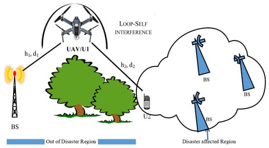
Figure 1.
UAV-assisted downlink Co-operative NOMA cellular system in a non-direct link post-disaster scenario.
The probability density function (PDF) of is represented by [45]
where B is the Weibull fading index, is a positive index and i represents the channel. B, also called the shape index, describes the fading severity while , known as the scale index, reveals the associated average power of the fading [48].
Accordingly, the channel power gains have also the Weibull distribution, but the shape index is changed to , and the scale index remains . The PDF of is given by [45]
A feedback channel over Weibull fading with coefficient represents the loop self-interference (LI), which exists in the UAV-FDR-NOMA system in the residual form. Further, this channel has its own fading parameters as and . The active BS allocates one of the resource blocks for transmitting the superposed signal of symbols and to in the power domain. obtains both the superposed and loop interference signals at the same instant [53]. The signal received at can be provided by [54]
where and are the powers at and the BS respectively for the normalized transmission; denotes the power allocation factor for symbol while, is for symbol . Both symbols and are of and , respectively; denotes the LI symbol. Suppose with , without losing generality. At , the NOMA principle is used to implement SIC [55]. Therefore, to decode the ’s symbol at , the obtained signal-to-interference and noise ratio (SINR) for symbol at is expressed as
where is the transmitted signal-to-noise ratio (SNR) and for FDR and HDR operation respectively. Note that means and are normalized unity power symbols, where the expectation operation is denoted by . The obtained SINR after SIC at , to decode its symbol is expressed as
The received signal in the FDR mode at in the non-direct link can be expressed as
The obtained SNR to detect symbol by in the non-direct link scenario is given by
3. System Performance
The outage probability and throughput are considered for examining the performance of the wireless communication UAV-HDR/FDR-NOMA system model where the quality of service (QoS) determines the target user rate. The probability that the obtained SNR will be lower than the threshold SNR or the achieved data rate will be lower than the target rate determines the outage probability of a communication system. Further, the throughput is based on the data rate obtained at the receiver without any outage. For successful decoding of symbols, and in the aforementioned UAV-FDR-NOMA system, and are considered to be the corresponding target rates which are stated in bits per channel usage (bpcu) [41]. SNR threshold values are and , respectively. The transmission of the symbols and will take place across two consecutive time slots if the HDR technique is utilized rather than the FDR approach [26]. As a result, the HDR system’s achievable rate is cut in half. The target rate of the UAV-HDR-NOMA system is kept equal to that of the UAV-FDR-NOMA system for a fair comparison. The values of the SNR threshold are given by and for symbols and , respectively.
3.1. Outage Probability
The outage performance over the Weibull fading channel can be determined under a non-direct link scenario in the downlink UAV-HDR/FDR-NOMA systems as follows.
3.1.1. Outage Probability of U1
The following are the complementary events that occur during the outage at : As per the NOMA procedure, is capable of detecting both symbols and . According to the preceding statement, the outage probability for is given by [56]
where , and is the target rate to detect while with is the target rate for detecting .
The outage probability in a UAV-FDR-NOMA system for using Equation (8) provides a theorem as follows.
Theorem 1.
The expression for the outage probability in the exact form for without a direct link is given by
where , , , , and .
Note that Equation (9) is derived in the partly closed-form expression.
Further, a complete closed-form expression is necessary to derive to simplify the calculation and better comprehend the system’s outage behavior. To address this issue, Equation (9) is reformulated to determine the asymptotic outage probability with simpler constraints for the same system as follows.
For without a direct link, the asymptotic outage probability expression is given by
Proof.
Consult Appendix A. □
Corollary 1.
The outage probability based on Equation (8) in the UAV-HDR-NOMA system with is given by
where and indicate the target SNRs for to detect corresponding symbols and under HD mode, and , and with .
3.1.2. Outage Probability of U2
The following are the interpretation for the occurrence of outages at . The initial is that is unable to recognize . The latter is that cannot recognize its own message , but can recognize . The outage probability based on these factors is calculated by [56]
The outage probability in the UAV-FDR-NOMA system is provided by the following theorem.
Theorem 2.
The outage probability expression in exact form for the under a non-direct link is given by
Note that Equation (14) is derived in the partly closed-form expression.
Further, a closed-form expression is necessary to derive to simplify the calculation and better comprehend the system’s outage behavior. To address this issue, Equation (14) is reformulated to determine the asymptotic outage probability with simpler constraints for the same system as follows.
For without a direct link, the asymptotic outage probability expression is given by
Proof.
Consult Appendix B. □
Corollary 2.
The outage probability expression in the UAV-HDR-NOMA system for under a non-direct link with is given by
Proof.
Consult Appendix C. □
3.2. Throughput
Throughput analysis for the UAV-HDR/FDR-NOMA systems, the delay-limited transmission modes [57,58] is considered in this subsection.
3.2.1. Throughput Analysis for UAV-FDR-NOMA
The BS transmits data in this mode at a constant rate of R, but there is a chance of an outage because of fading wireless channels. Without a direct link, the UAV-FDR-NOMA system’s throughput is given by [56]
3.2.2. Throughput Analysis for UAV-HDR-NOMA
The UAV-HDR-NOMA system’s throughput without a direct link, similar to Equation (18), is given by [56]
4. Simulations and Performance Evaluation Results
The two performance metrics as outage probability and throughput for the UAV-HDR/FDR-based NOMA systems with DF relaying protocol under Weibull fading channels are demonstrated in this paper. This section discusses the performance of the downlink channel in a single active BS with two users under a non-direct link between and the BS scenario. Following that, Monte Carlo simulations are conducted through a collection of channel realizations to compare the outage probability as well as the throughput performance results obtained in the exact analytical form for the UAV-HDR/FDR-NOMA systems. Initially, the outage and throughput performance for under Weibull distribution is observed and compared to the curves plotted through [56] for the same performance metrics under Rayleigh fading for both UAV-HDR-NOMA and UAV-FDR-NOMA systems. Further, for values, the comparative outage, and throughput performance are evaluated for the same systems and compared to the standard orthogonal multiple access (OMA) systems. Without losing generality, considering the same as [56] and , where p is the path loss exponent set to . is the normalized distance between and set to be and . The power allocation coefficient is assumed to be as well as for and in the NOMA system, respectively.
4.1. Comparison between UAV-HDR/FDR-Based NOMA and OMA over Special Case of Weibull Fading for B=2 (Rayleigh Fading)
The Monte-Carlo-simulated results for outage and system throughput performance in Weibull distribution for almost resemble the performance for the same in Rayleigh fading in the downlink as shown in Figure 2 and Figure 3, respectively. The performance metrics in the UAV-HDR/FDR-NOMA systems are compared to a conventional OMA system.
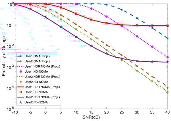
Figure 2.
Outage probability versus the SNR for and under UAV−HDR/FDR−based NOMA and OMA schemes with ( Rayleigh fading based HD/FD−NOMA [56]).
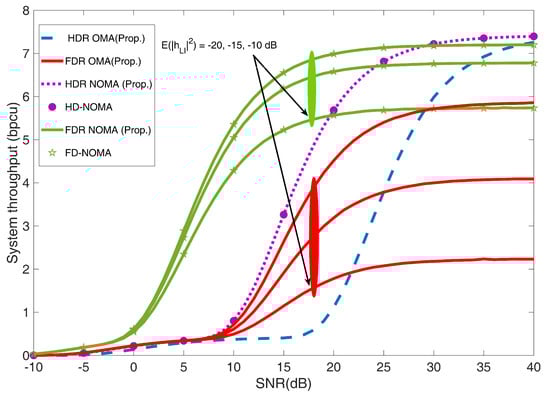
Figure 3.
System throughput versus SNR for UAV-HDR/FDR−based NOMA and OMA schemes with different values of LI for (Rayleigh fading based HD/FD−NOMA [56]).
According to Equations (9), (12), (14) and (17), the outage probability with the exact theoretical curves of two users is plotted in Figure 2 under UAV-HDR/FDR-based NOMA systems considering the LI value to be −15 dB. Additionally, it is observed from Figure 2 that the outage probability curves in exact form resemble the curves presented for Rayleigh fading through [56]. In terms of outage performance, the UAV-FDR-NOMA system outperforms UAV-HDR-based NOMA and OMA systems under the low SNR regime which resembles Equations (11) and (16). This is because in the low SNR regime, loop interference (LI) has no substantial impact on the UAV-FDR-NOMA system. It is also worth noting that the outage behavior for the UAV-HDR-NOMA system outperforms that of the UAV-HDR-OMA system as shown in Figure 2. For UAV-FDR-NOMA users, the exact performance curves for the outage probability in the high SNR regime are well approximated with Equations (10) and (15). In UAV-FDR-NOMA, error floors are demonstrated to exist. This is because UAV-FDR-NOMA has loop interference. Another finding in the high SNR region is that UAV-HDR-based NOMA and OMA outperform UAV-FDR-NOMA. As a result, in practical UAV-HDR/FDR-based NOMA systems, alternative operation modes can be selected for user relaying depending on SNR levels.
Figure 3 shows the system throughput vs. SNR without a direct link, and the curves presented for the system throughput of the UAV-HDR/FDR-NOMA system closely resemble the curves drawn for the same over the Rayleigh distribution by [56]. The curves also reflect UAV-HDR/FDR-NOMA without direct link throughput, as calculated by Equations (18) and (19), respectively. UAV-FDR-NOMA has a better throughput than UAV-HDR-NOMA and UAV-HDR/FDR-OMA in the low SNR regime with a −10 dB LI value, as can be seen from Figure 3. Further observation shows that decreasing the LI values from −10 dB to −20 dB increases the system throughput of UAV-FDR-NOMA as well as UAV-FDR-OMA in the high SNR regime. The system throughput of UAV-FDR-NOMA with a −20 dB LI value reaches almost the maximum throughput value of UAV-HDR-based-NOMA and OMA systems in the high SNR regime. This is because, in the high SNR regime, UAV-FDR-NOMA converges to an error floor.
4.2. Comparison between UAV-HDR/FDR Based-NOMA and OMA in Various Fading Conditions over Weibull Fading
Over a Weibull fading channel, the performance of UAV-HDR/FDR-NOMA is compared to that of a UAV-HDR/FDR-OMA system under this section. An OMA technique is proposed at the active BS level in which power control is taken into account, the same as NOMA. It means that the power allocated to is , while that for is , and satisfied by a condition . For a fair comparison of performance between NOMA and OMA, the target rates are set to be equal and the corresponding SNR criteria are established. The rate that can be obtained is lowered since OMA needs more time slots to finish the whole transmission. The threshold SNR requirement under OMA for both and rises due to the same target rates for the NOMA as well as OMA systems.
4.2.1. UAV-HDR Based-NOMA and OMA
Under this sub-section, the outage probability as well as user throughput of UAV-HDR-NOMA is compared to that of the UAV-HDR-OMA system, which uses three o complete communication. The BS in the first time slot sends the symbol to , gets decoded at the completion of the same time slot by , and sends to in the second time slot [41]. decodes and sends the information to in the third or final slot. It is worth noting that when UAV-HDR-OMA is used, the decoding at occurs in the absence of interference caused by or , and this is due to taking one extra time slot by UAV-HDR-OMA because of the orthogonal signal transmission, which further requires higher SNR for the same target rate.
In Figure 4, the outage probability curves in exact form for the two users under UAV-HDR-NOMA are presented based on Equations (12) and (17), accordingly. The Monte Carlo simulation results match the exact outage probability curves. Figure 4 shows that when the value of B increases from 2 to 4 by one, the outage performance of the UAV-HDR based-NOMA and OMA systems begins to improve after attaining a specific value of the SNR. However, in every fading condition for both users, the UAV-HDR-NOMA system outperforms the UAV-HDR-OMA system individually.
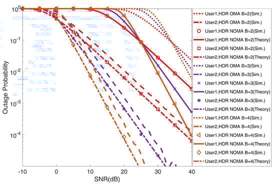
Figure 4.
Outage probability versus SNR for and under UAV−HDR based− NOMA and OMA schemes.
Figure 5 shows the outage probability of and considering the distance between BS and at a receiving SNR value of 15 dB. It is observed from this Figure that as the value of separation distance of UAV from BS increases, the outage probability in UAV-HDR based-NOMA and OMA systems continuously increases, while for , it first decreases up to a certain distance and further starts to increase. Thus, at this certain distance, gets the minimum outage. This points to the minimum outage optimal location for a UAV to be deployed. Further, the plotted curves for and meet on a particular point in every fading scenario i.e., which shows fair outage conditions for both users. This shows the fair outage optimal location for the UAV deployment under UAV-HDR-NOMA/OMA systems. Further, this optimal location for the UAV deployments shifts towards the BS by increasing the value of B by one from 2 to 4 under the same systems. Notice that for the outage performance for the whole range of distance considerations, UAV-HDR-OMA outperforms UAV-HDR-NOMA for a shorter deploying distance of UAV while for the longer distance, the UAV-HDR-NOMA system surpasses the UAV-HDR-OMA system.
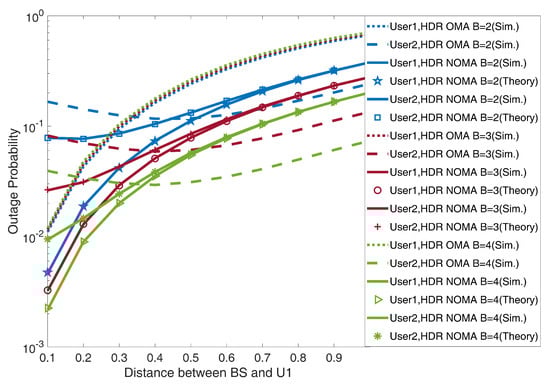
Figure 5.
Outage probability versus distance of U1, i.e., UAV from BS for and under UAV−HDR based−NOMA and OMA schemes.
Figure 6 observes the user throughput of and by alternating the separation distance of from under the UAV-HDR-based NOMA and OMA systems. It can be seen in Figure 6 that the throughput of for the HDR-OMA system decreases with an increment in the separation distance of from the BS. At the same time, for , it first increases up to a particular distance and after that starts to decrease. Thus, at this particular distance, gets the maximum throughput, and this distance is the optimal location for deploying a UAV in an HDR-NOMA system. Further, the throughput curves of and in HDR-OMA systems meet on a single point in every fading condition, i.e., which shows the fair throughput condition for both users and this characterizes fair throughput optimal location for the deployment of a UAV. Moreover, this UAV location shifts toward BS as the value of B increases from 2 to 4. Further for the HDR-NOMA system, it can be seen in Figure 6 that the throughput of is initially higher than that of but both user curves for the same start continuously decreasing with increasing the deployment distance of UAV from the BS and finally overlap with each other for a range of distance from the BS. This range of distance shows a fair throughput optimal location zone for the UAV deployment under the HDR-NOMA system. It is worth noticing that the fair throughput optimal location zone shifts towards the BS with an increment in the value of B from 2 to 4. Moreover, the maximum throughput value distance for is the maximum throughput optimal location for the deployment of a UAV in the HDR-NOMA systems. In addition, both users’ throughput for the UAV-HDR-NOMA system shows to always be better than the UAV-HDR-OMA system irrespective of any separation distance of with the BS. However, the throughput for both users increases with an increase in the Weibull shaping index value by one, from 2 to 4.
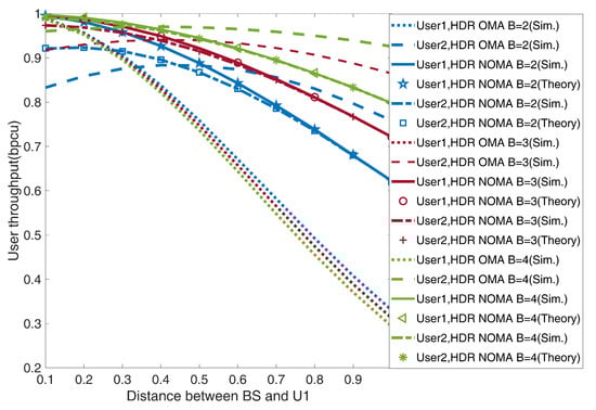
Figure 6.
User throughput versus distance of U1, i.e., UAV from BS for UAV-HDR based-NOMA and OMA schemes in delay-limited transmission mode.
4.2.2. UAV-FDR Based-NOMA and OMA
Under this sub-section, the UAV-FDR-NOMA system’s outage and user throughput performance are compared to that of a UAV-FDR-OMA system, in which transmission is carried in two-time slots. The symbol is delivered to by the BS at the beginning of the first time slot and is decoded by at the completion of the same time slot. Further, the symbol is transferred to by the BS in the second time slot, which is decoded and forwarded by to . Because is in FD mode, simultaneous receipt and transmission occur at , allowing to be decoded in the same time slot at with a slight processing delay.
Figure 7 compares the outage performance of and versus SNR under UAV-FDR based-NOMA and OMA systems. It can be observed from Figure 7 that the outage probability of and decreases with increasing the SNR value in both systems. However, becomes affected by self-loop interference under the UAV-FDR-NOMA/OMA system, and as a result, the SNR at degrades, and experiences a longer outage than in the high SNR regime. Similar results for the outage performance are also shown in Figure 7, where both of the curves for FDR-NOMA and OMA at high SNR resemble Equations (10) and (15). Further, the outage performance of degrades, while that of outperforms by increasing the value of B by one from 2 to 4. Notice that throughout the whole range of transmit power considerations, the UAV-FDR-NOMA system surpasses the UAV-FDR-OMA-based scheme in terms of the performance.
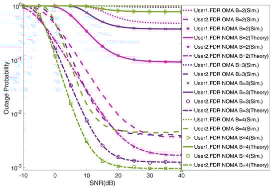
Figure 7.
Outage probability of and versus SNR for UAV-FDR based-NOMA and OMA schemes ().
Figure 8 points to the outage probability curves for as well as under the UAV-FDR based-NOMA and OMA systems drawn over the distance between and , i.e., UAV. It is observed from this figure that as the value of the separation distance of UAV from BS increases, the outage probability curves under for in the UAV-FDR based-NOMA and OMA systems continuously increase, while for , it first decreases up to a certain distance and further starts to increase. Thus, at this certain distance, gets minimum outage conditions. This shows the minimum outage optimal location for the UAV deployment. Moreover, this optimal location shifts towards the BS with an increase in the value of B by one from 2 to 4. Further, the plotted curves for and meet on a particular point for the fading scenario which shows fair outage conditions for both users. This represents the fair outage optimal location for the UAV deployment. This optimal location also shifts toward the BS by increasing the value of B from 2 to 4. However, for , the figure is not showing the optimal location point, but by analyzing the trends of the curves drawn for U1 and U2, it can assume that both curves may meet at a point very close to the BS. It is worth noticing that for the deployment of a UAV beyond this optimal location, attains a greater outage probability than .
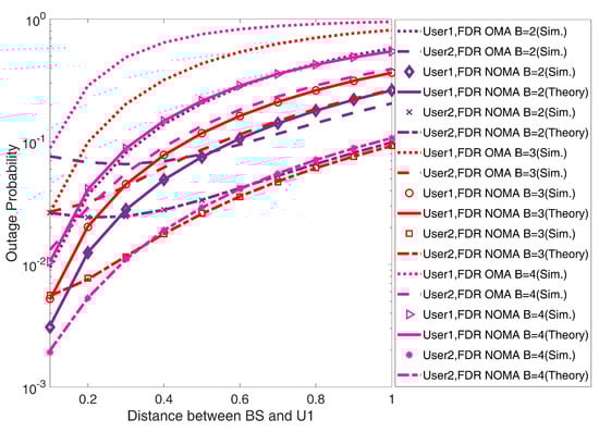
Figure 8.
Outage probability versus distance of i.e., UAV from BS for and in UAV-FDR based-NOMA and OMA schemes ().
Figure 9 observes the impact of the separation distance of , i.e., UAV with on the user throughput of and under the UAV-FDR based-NOMA and OMA systems under the receiving SNR value of 15 dB. From Figure 9A, it can be seen that Under , the throughput of decreases with an increment in the separation distance of from the BS while for , it first increases up to a particular distance and after that starts to decrease. Thus, at this particular distance, gets the maximum throughput condition. This shows the maximum throughput optimal location for the deployment of a UAV. Moreover, this optimal location approaches closer to the BS With the increase in the value of B for the throughput of in both systems as can be observed from Figure 9B. Further, the throughput curves of and meet on a single point in every fading condition, i.e., , which shows fair throughput conditions for both users. This represents a fair throughput optimal location for the deployment of UAV in both systems. In addition, both users’ throughput for the UAV-FDR-NOMA system shows to always higher than the UAV-FDR-OMA system, irrespective of any separation distance of with the BS. However, the throughput for both users increases with an increase in the Weibull shaping index value by one from 2 to 4.
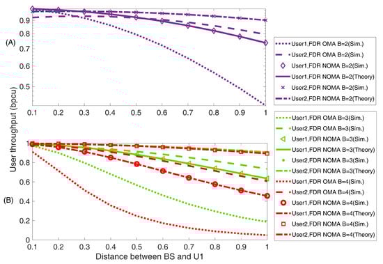
Figure 9.
User throughput versus distance of U1, i.e., UAV from BS for UAV-FDR based-NOMA and OMA schemes in delay-limited transmission mode ().
4.2.3. UAV-HDR/FDR-Based NOMA and OMA
The far-user throughput for the UAV-HDR/FDR-NOMA system is compared to that of the UAV-HDR/FDR-OMA system under this subsection.
From the plotted Figure 10A,B, it can be seen that the throughput in UAV-FDR-NOMA is higher than UAV-HDR/FDR-OMA as well as UAV-HDR-NOMA under every fading channel conditions (i.e., for ) individually for the short-distance deployment of UAV from the BS. However, throughput slope variations in HDR-NOMA are much more than FDR-NOMA with increasing the deployment distance of UAV from the BS. It means throughput performance degradation under longer distance deployment of UAV is very high in HDR-NOMA systems, while that for FDR-NOMA systems is much less. Further, as the Weibull shaping index B increases by one from 2 to 4 in the mid-range deployment distance of UAV, the throughput gap between HDR-OMA and FDR-NOMA in the same fading condition decreases, and finally, at , this gap becomes zero, i.e, far-user throughput curve for HDR-OMA approaches more to cross the curve drawn for the same under FDR-NOMA by meeting at a particular point. This shows that a lower value of B is a favorable condition for the throughput performance of FDR-NOMA systems outperforming HDR-OMA systems.
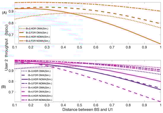
Figure 10.
Cell-edge or far-user throughput versus distance of for UAV-HDR/FDR based-NOMA and OMA schemes ().
5. Conclusions
Outage probability and throughput for a UAV equipped with HDR/FDR under two-user NOMA systems are presented in a post-disaster situation. The Weibull shaping index, the separation distance of UAV with BS, and the SNR in the non-direct downlink scenario are used to quantify the performance. The numerical results reveal that the outage and throughput performance metrics for the far-user improve by increasing the Weibull shaping index value irrespective of the NOMA or OMA system. Further, the next numerical results conclude that the derived expressions assist in finding the optimal UAV location from the BS in fixed power allocated UAV-HDR/FDR-NOMA systems to improve the throughput of the far user. In this perspective, it is noteworthy to mention that despite having residual loop self-interference, the UAV-FDR-NOMA system shows significant improvement compared to UAV-HDR-based NOMA and OMA systems. In addition, the optimal location for the UAV deployment more closely approaches the BS by improving the value of B under the UAV-HDR/FDR-NOMA systems. The presented research work can be extended using the user pairing algorithm as well as deploying multi-UAVs for multi-user disaster management model scenarios. Additionally, the shadowed fading channels can be included in the system model as a future aspect of the work. Moreover, imperfect successive interference cancellation techniques under imperfect channel state information cases may be implemented at the receiving nodes to highlight the more practical scenario.
Author Contributions
Conceptualization, R.K. and S.K.; methodology, R.K. and S.K.; software, R.K.; validation, R.K.; formal analysis, R.K.; investigation, R.K.; resources, R.K.; data curation, R.K.; writing—original draft preparation, R.K.; writing—review and editing, R.K. and S.K.; visualization, R.K. and S.K.; supervision, S.K.; funding acquisition, R.K. All authors have read and agreed to the published version of the manuscript.
Funding
This research was funded by University Grants Commission: 34808/(NET-DEC.2014).
Institutional Review Board Statement
Not applicable.
Informed Consent Statement
Not applicable.
Acknowledgments
I thank Arvind Kumar and Saurabh Srivastava for their valuable input. I extend my gratitude to UGC for funding my research work.
Conflicts of Interest
The authors declare no conflict of interest.
Appendix A. Proof of Theorem 1
Appendix B. Proof of Theorem 2
Proof.
By definition, the first and second outage events are denoted by and , respectively, and calculated as [56]
By performing a few algebraic operations, is given by
Now, is given by
By performing a few algebraic operations, is given by
Appendix C. Proof of Corollary 2
References
- Hein, D.; Bayer, S.; Berger, R.; Kraft, T.; Lesmeister, D. An integrated rapid mapping system for disaster management. Int. Arch. Photogramm. Remote. Sens. Spat. Inf. Sci.-Isprs Arch. 2017, 42, 499–504. [Google Scholar] [CrossRef]
- Li, S.; Derakhshani, M.; Lambotharan, S.; Hanzo, L. Outage probability analysis for the multi-carrier NOMA downlink relying on statistical CSI. IEEE Trans. Commun. 2020, 68, 3572–3587. [Google Scholar] [CrossRef]
- Zhan, P.; Yu, K.; Swindlehurst, A.L. Wireless relay communications with unmanned aerial vehicles: Performance and optimization. IEEE Trans. Aerosp. Electron. Syst. 2011, 47, 2068–2085. [Google Scholar] [CrossRef]
- Zeng, Y.; Zhang, R.; Lim, T.J. Wireless communications with unmanned aerial vehicles: Opportunities and challenges. IEEE Commun. Mag. 2016, 54, 36–42. [Google Scholar] [CrossRef]
- Hentati, A.I.; Fourati, L.C.; Rezgui, J. Cooperative UAVs framework for Mobile Target Search and tracking. Comput. Electr. Eng. 2022, 101, 107992. [Google Scholar] [CrossRef]
- Erdelj, M.; Natalizio, E. UAV-assisted disaster management: Applications and open issues. In Proceedings of the 2016 International Conference on Computing, Networking and Communications (ICNC), Kauai, HI, USA, 15–18 February 2016; pp. 1–5. [Google Scholar]
- Wang, Y.; Su, Z.; Zhang, N.; Fang, D. Disaster relief wireless networks: Challenges and solutions. IEEE Wirel. Commun. 2021, 28, 148–155. [Google Scholar] [CrossRef]
- Luo, C.; Miao, W.; Ullah, H.; McClean, S.; Parr, G.; Min, G. Unmanned aerial vehicles for disaster management. In Geological Disaster Monitoring Based on Sensor Networks; Springer: Berlin/Heidelberg, Germany, 2019; pp. 83–107. [Google Scholar]
- Matracia, M.; Kishk, M.A.; Alouini, M.S. On the topological aspects of UAV-assisted post-disaster wireless communication networks. IEEE Commun. Mag. 2021, 59, 59–64. [Google Scholar] [CrossRef]
- Erdelj, M.; Król, M.; Natalizio, E. Wireless sensor networks and multi-UAV systems for natural disaster management. Comput. Netw. 2017, 124, 72–86. [Google Scholar] [CrossRef]
- Nguyen, L.D.; Nguyen, K.K.; Kortun, A.; Duong, T.Q. Real-time deployment and resource allocation for distributed UAV systems in disaster relief. In Proceedings of the 2019 IEEE 20th International Workshop on Signal Processing Advances in Wireless Communications (SPAWC), Cannes, France, 2–5 July 2019; pp. 1–5. [Google Scholar]
- Al-Hourani, A.; Kandeepan, S.; Lardner, S. Optimal LAP altitude for maximum coverage. IEEE Wirel. Commun. Lett. 2014, 3, 569–572. [Google Scholar] [CrossRef]
- Mozaffari, M.; Saad, W.; Bennis, M.; Debbah, M. Drone small cells in the clouds: Design, deployment and performance analysis. In Proceedings of the 2015 IEEE Global Communications Conference (GLOBECOM), San Diego, CA, USA, 6–10 December 2015; pp. 1–6. [Google Scholar]
- Duc, C.H.; Nguyen, S.Q.; Le, C.B.; Khanh, N.T.V. Performance Evaluation of UAV-Based NOMA Networks with Hardware Impairment. Electronics 2021, 11, 94. [Google Scholar] [CrossRef]
- Qin, X.; Wu, X.; Xiong, M.; Liu, Y.; Zhang, Y. Multi-UAV Clustered NOMA for Covert Communications: Joint Resource Allocation and Trajectory Optimization. Electronics 2022, 11, 4056. [Google Scholar] [CrossRef]
- Saif, A.; Dimyati, K.; Noordin, K.A.; Alsamhi, S.H.; Hawbani, A. Multi-UAV and SAR collaboration model for disaster management in B5G networks. Internet Technol. Lett. 2021, e310. [Google Scholar] [CrossRef]
- Trotta, A.; Andreagiovanni, F.D.; Di Felice, M.; Natalizio, E.; Chowdhury, K.R. When UAVs ride a bus: Towards energy-efficient city-scale video surveillance. In Proceedings of the IEEE Infocom 2018-IEEE Conference on Computer Communications, Honolulu, HI, USA, 15–19 April 2018; pp. 1043–1051. [Google Scholar]
- Han, S.I.; Baek, J. Optimal UAV Deployment and Resource Management in UAV Relay Networks. Sensors 2021, 21, 6878. [Google Scholar] [CrossRef] [PubMed]
- Shakhatreh, H.; Alenezi, A.; Sawalmeh, A.; Almutiry, M.; Malkawi, W. Efficient placement of an aerial relay drone for throughput maximization. Wirel. Commun. Mob. Comput. 2021, 2021, 11. [Google Scholar] [CrossRef]
- Mozaffari, M.; Saad, W.; Bennis, M.; Debbah, M. Efficient deployment of multiple unmanned aerial vehicles for optimal wireless coverage. IEEE Commun. Lett. 2016, 20, 1647–1650. [Google Scholar] [CrossRef]
- ur Rahman, S.; Kim, G.H.; Cho, Y.Z.; Khan, A. Positioning of UAVs for throughput maximization in software-defined disaster area UAV communication networks. J. Commun. Netw. 2018, 20, 452–463. [Google Scholar] [CrossRef]
- Elnabty, I.A.; Fahmy, Y.; Kafafy, M. A survey on UAV placement optimization for UAV-assisted communication in 5G and beyond networks. Phys. Commun. 2022, 51, 101564. [Google Scholar] [CrossRef]
- Duong, T.Q.; Kim, K.J.; Kaleem, Z.; Bui, M.P.; Vo, N.S. UAV caching in 6G networks: A Survey on models, techniques, and applications. Phys. Commun. 2022, 51, 101532. [Google Scholar] [CrossRef]
- Ding, Z.; Liu, Y.; Choi, J.; Sun, Q.; Elkashlan, M.; Chih-Lin, I.; Poor, H.V. Application of non-orthogonal multiple access in LTE and 5G networks. IEEE Commun. Mag. 2017, 55, 185–191. [Google Scholar] [CrossRef]
- Shimojo, T.; Umesh, A.; Fujishima, D.; Minokuchi, A. Special articles on 5G technologies toward 2020 deployment. NTT DOCOMO Tech. J. 2016, 17, 50–59. [Google Scholar]
- Kim, J.B.; Lee, I.H. Non-orthogonal multiple access in coordinated direct and relay transmission. IEEE Commun. Lett. 2015, 19, 2037–2040. [Google Scholar] [CrossRef]
- Al-Abbasi, Z.Q.; Farhan, L.; Alhumaima, R.S. Multiple-Intelligent Reflective Surfaces (Multi-IRSs)-Based NOMA System. Electronics 2022, 11, 4045. [Google Scholar] [CrossRef]
- Ding, Z.; Peng, M.; Poor, H.V. Cooperative non-orthogonal multiple access in 5G systems. IEEE Commun. Lett. 2015, 19, 1462–1465. [Google Scholar] [CrossRef]
- Wang, L.; Hu, B.; Chen, S.; Cui, J. UAV-enabled reliable mobile relaying based on downlink NOMA. IEEE Access 2020, 8, 25237–25248. [Google Scholar] [CrossRef]
- Zhang, J.; Zheng, X.; Pan, G.; Xie, Y. On secrecy analysis of UAV-enabled relaying NOMA systems. Phys. Commun. 2021, 45, 101263. [Google Scholar] [CrossRef]
- Nguyen, L.M.D.; Vo, V.N.; So-In, C.; Dang, V.H. Throughput analysis and optimization for NOMA Multi-UAV assisted disaster communication using CMA-ES. Wirel. Netw. 2021, 27, 4889–4902. [Google Scholar] [CrossRef]
- Liu, M.; Yang, J.; Gui, G. DSF-NOMA: UAV-assisted emergency communication technology in a heterogeneous Internet of Things. IEEE Internet Things J. 2019, 6, 5508–5519. [Google Scholar] [CrossRef]
- Zhai, D.; Li, H.; Tang, X.; Zhang, R.; Ding, Z.; Yu, F.R. Height optimization and resource allocation for NOMA enhanced UAV-aided relay networks. IEEE Trans. Commun. 2020, 69, 962–975. [Google Scholar] [CrossRef]
- Barick, S.; Singhal, C. Multi-UAV Assisted IoT NOMA Uplink Communication System for Disaster Scenario. IEEE Access 2022, 10, 34058–34068. [Google Scholar] [CrossRef]
- Do, N.T.; Da Costa, D.B.; Duong, T.Q.; An, B. A BNBF user selection scheme for NOMA-based cooperative relaying systems with SWIPT. IEEE Commun. Lett. 2016, 21, 664–667. [Google Scholar] [CrossRef]
- Men, J.; Ge, J.; Zhang, C. Performance analysis of nonorthogonal multiple access for relaying networks over Nakagami-m fading channels. IEEE Trans. Veh. Technol. 2016, 66, 1200–1208. [Google Scholar] [CrossRef]
- Ju, H.; Oh, E.; Hong, D. Improving efficiency of resource usage in two-hop full duplex relay systems based on resource sharing and interference cancellation. IEEE Trans. Wirel. Commun. 2009, 8, 3933–3938. [Google Scholar]
- Wei, S.; Li, J.; Chen, W.; Zheng, L.; Su, H. Design of generalized analog network coding for a multiple-access relay channel. IEEE Trans. Commun. 2014, 63, 170–185. [Google Scholar] [CrossRef]
- Zhang, L.; Liu, J.; Xiao, M.; Wu, G.; Liang, Y.C.; Li, S. Performance analysis and optimization in downlink NOMA systems with cooperative full-duplex relaying. IEEE J. Sel. Areas Commun. 2017, 35, 2398–2412. [Google Scholar] [CrossRef]
- Zheng, H.E.T.; Madhukumar, A.; Sirigina, R.P.; Krishna, A.K. An outage probability analysis of full-duplex NOMA in UAV communications. In Proceedings of the 2019 IEEE Wireless Communications and Networking Conference (WCNC), Marrakesh, Morocco, 15–18 April 2019; pp. 1–5. [Google Scholar]
- Aswathi, V.; Babu, A.V. Non-orthogonal multiple access in full-duplex-based coordinated direct and relay transmission (CDRT) system: Performance analysis and optimization. EURASIP J. Wirel. Commun. Netw. 2020, 2020, 1–27. [Google Scholar]
- Nguyen, A.N.; Vo, V.N.; So-In, C.; Ha, D.B. System performance analysis for an energy harvesting IoT system using a DF/AF uav-enabled relay with downlink NOMA under nakagami-m fading. Sensors 2021, 21, 285. [Google Scholar] [CrossRef] [PubMed]
- Khuwaja, A.A.; Chen, Y.; Zhao, N.; Alouini, M.S.; Dobbins, P. A survey of channel modeling for UAV communications. IEEE Commun. Surv. Tutorials 2018, 20, 2804–2821. [Google Scholar] [CrossRef]
- Yan, C.; Fu, L.; Zhang, J.; Wang, J. A comprehensive survey on UAV communication channel modeling. IEEE Access 2019, 7, 107769–107792. [Google Scholar] [CrossRef]
- Cheng, J.; Tellambura, C.; Beaulieu, N.C. Performance analysis of digital modulations on Weibull fading channels. In Proceedings of the 2003 IEEE 58th Vehicular Technology Conference, VTC 2003-Fall (IEEE Cat. No. 03CH37484), Orlando, FL, USA, 6–9 October 2003; Volume 1, pp. 236–240. [Google Scholar]
- Hashemi, H. The indoor radio propagation channel. Proc. IEEE 1993, 81, 943–968. [Google Scholar] [CrossRef]
- Tzeremes, G.; Christodoulou, C. Use of Weibull distribution for describing outdoor multipath fading. In Proceedings of the IEEE Antennas and Propagation Society International Symposium (IEEE Cat. No. 02CH37313), San Antonio, TX, USA, 16–21 June 2002; Volume 1, pp. 232–235. [Google Scholar]
- Li, X.; Li, J.; Li, L. Performance analysis of impaired SWIPT NOMA relaying networks over imperfect Weibull channels. IEEE Syst. J. 2019, 14, 669–672. [Google Scholar] [CrossRef]
- Gupta, M.; Anandpushparaj, J.; Muthuchidambaranathan, P.; Jayakody, D.N.K. Outage performance comparison of dual-hop half/full duplex wireless UAV system over weibull fading channel. In Proceedings of the 2020 International Conference on Wireless Communications Signal Processing and Networking (WiSPNET), Chennai, India, 4–6 August 2020; pp. 177–181. [Google Scholar]
- Jeganathan, A.; Mitali, G.; Jayakody, D.N.K.; Muthuchidambaranathan, P. Outage and throughput performance of half/full-duplex UAV-assisted co-operative relay networks over Weibull fading channel. Wirel. Pers. Commun. 2021, 120, 2389–2407. [Google Scholar] [CrossRef]
- Chiaraviglio, L.; D’Andreagiovanni, F.; Liu, W.; Gutierrez, J.A.; Blefari-Melazzi, N.; Choo, K.K.R.; Alouini, M.S. Multi-area throughput and energy optimization of UAV-aided cellular networks powered by solar panels and grid. IEEE Trans. Mob. Comput. 2020, 20, 2427–2444. [Google Scholar] [CrossRef]
- Bello, A.B.; Navarro, F.; Raposo, J.; Miranda, M.; Zazo, A.; Álvarez, M. Fixed-Wing UAV Flight Operation under Harsh Weather Conditions: A Case Study in Livingston Island Glaciers, Antarctica. Drones 2022, 6, 384. [Google Scholar] [CrossRef]
- Ding, Z.; Yang, Z.; Fan, P.; Poor, H.V. On the performance of non-orthogonal multiple access in 5G systems with randomly deployed users. IEEE Signal Process. Lett. 2014, 21, 1501–1505. [Google Scholar] [CrossRef]
- Kumar, R.; Kumar, S. Sum rate DL/UL performance of co-operative NOMA systems over Weibull fading channel. J. Mob. Multimed. 2021, 17, 361–384. [Google Scholar] [CrossRef]
- Riihonen, T.; Werner, S.; Wichman, R. Hybrid full-duplex/half-duplex relaying with transmit power adaptation. IEEE Trans. Wirel. Commun. 2011, 10, 3074–3085. [Google Scholar] [CrossRef]
- Yue, X.; Liu, Y.; Kang, S.; Nallanathan, A.; Ding, Z. Exploiting full/half-duplex user relaying in NOMA systems. IEEE Trans. Commun. 2017, 66, 560–575. [Google Scholar] [CrossRef]
- Liu, Y.; Ding, Z.; Elkashlan, M.; Poor, H.V. Cooperative non-orthogonal multiple access with simultaneous wireless information and power transfer. IEEE J. Sel. Areas Commun. 2016, 34, 938–953. [Google Scholar] [CrossRef]
- Zhong, C.; Suraweera, H.A.; Zheng, G.; Krikidis, I.; Zhang, Z. Wireless information and power transfer with full duplex relaying. IEEE Trans. Commun. 2014, 62, 3447–3461. [Google Scholar] [CrossRef]
Disclaimer/Publisher’s Note: The statements, opinions and data contained in all publications are solely those of the individual author(s) and contributor(s) and not of MDPI and/or the editor(s). MDPI and/or the editor(s) disclaim responsibility for any injury to people or property resulting from any ideas, methods, instructions or products referred to in the content. |
© 2023 by the authors. Licensee MDPI, Basel, Switzerland. This article is an open access article distributed under the terms and conditions of the Creative Commons Attribution (CC BY) license (https://creativecommons.org/licenses/by/4.0/).