Article

An Approach towards Designing Logic Locking Using Shape-Perpendicular Magnetic Anisotropy-Double Layer MTJ

Innovative Technologies Laboratories (ITL), King Abdullah University of Science and Technology (KAUST), Thuwal 23955-6900, Saudi Arabia
*
Author to whom correspondence should be addressed.
Electronics 2023, 12(3), 479; https://doi.org/10.3390/electronics12030479
Submission received: 14 December 2022 / Revised: 8 January 2023 / Accepted: 16 January 2023 / Published: 17 January 2023
(This article belongs to the Section Semiconductor Devices)

Abstract

:
In recent years, discovering various vulnerabilities in the IC supply chain has raised security concerns in electronic systems. Recent research has proposed numerous attack and defense mechanisms involving various nanoelectronic devices. Spintronic devices are a viable choice among various nanoelectronic devices because of their non-volatility, ease of fabrication with a silicon substrate, randomization in space and time, etc. This work uses a shape-perpendicular magnetic anisotropy-double oxide layer magnetic tunnel junction (s-PMA DMTJ) to construct a potential logic-locking (LL) defensive mechanism. s-PMA DMTJs can be used for more realistic novel solutions of secure hardware design due to their improved thermal stability and area efficiency compared to traditional MTJs. The LL system’s critical design range and viability are investigated in this work and compared with other two-terminal MTJ designs using various circuit analysis techniques, such as Monte Carlo simulations, eye diagram analysis, transient measurement, and parametric simulations. Hamming Distance of 25%, and output corruption coverage of 100% are achieved in the investigated test circuit.

1. Introduction

The globalization of the custom integrated circuits design to reduce the cost of production and speed up ICs manufacturing has increased the threats such as counterfeiting, IC overbuilding, IP piracy, hardware Trojans, and reverse engineering [1]. In the context of hardware security, logic locking is one of the promising obfuscation methodologies [2]. Security measures come with an expense with extra hardware, and intelligent attackers may decipher the security mechanism by several techniques such as reverse engineering, side-channel analysis [3], etc. This motivates recent research towards exploring novel hardware solutions for use in hardware security. With the emergence of beyond CMOS devices for various applications due to their unique inherent physical characteristics, the avenue for both novel threats and security mechanisms at the hardware level becomes significant. Spintronics devices have gained much interest as a prime candidate for several emerging phenomena and applications such as non-volatile memories, bio-inspired computing, all spin logic operations [4,5,6,7]. The spatial and temporal randomness in the magnetic system, inherent noise, simplicity of integration with a silicon substrate, and various other properties of spintronics devices can be utilized in creating novel hardware security trust infrastructure [8].
One spintronic device that has received much attention is the Magnetic Tunnel Junction (MTJ). It has been utilized for several hardware security primitives, including logic locking, hardware Trojans, physically unclonable functions (PUFs), and true random number generators [9,10,11,12]. This work employs s-PMA DMTJ Verilog-A model for logic-locking applications [13]. A two-terminal (2T) spin-transfer torque (STT) MTJ suffers from endurance problems due to passing a large write current through the thin oxide layer at scaled technology nodes [14,15]. Other three-terminal (3T) spin-orbit-torque (SOT) assisted MTJs have been developed in response to this [16,17]. These devices have additional heavy metal/anti-ferromagnet layers to pass the writing current. This allows the structure to have a lower current passed through the MTJ thin oxide layer and decoupled read and write operation, but the area consumption increases in such a structure. To mitigate these challenges and increase the downsize scalability, shape anisotropy effect [18,19] can allow the MTJ dimension to be scaled down to the sub-micron level. The s-PMA DMTJ also has high thermal stability, low operational voltage, and high reliability, thus making them useful for high-density spintronic memory and logic applications [13]. The advantages and challenges of using emerging 2T/3T MTJ devices for the LL mechanism are discussed in [12]. Figure 1 shows the LL flow in the system-on-chip (SoC) design process. Several untrusted entities are involved in the process, as shown in Figure 1, from the design house, foundry, and assembly facility. The IP owner locks the netlist and stores the specific key values in tamper-proof memory. Traditional LL techniques can counter untrusted foundries, but deploying any beyond-CMOS devices will require a specialized foundry, which is currently a potential drawback.
The rest of the paper is organized as follows: Section 2 discusses the background of the work. Section 3 describes the simulation setup used during the simulation. Several circuit analysis techniques are used to demonstrate the ability to perform satisfactory LL operations. The experimental results are presented in Section 4. Section 5 discusses the security aspect and current significant challenges for such emerging devices-based LL systems, and Section 6 finally concludes the paper.

2. Background

2.1. s-PMA Double Barrier MTJ

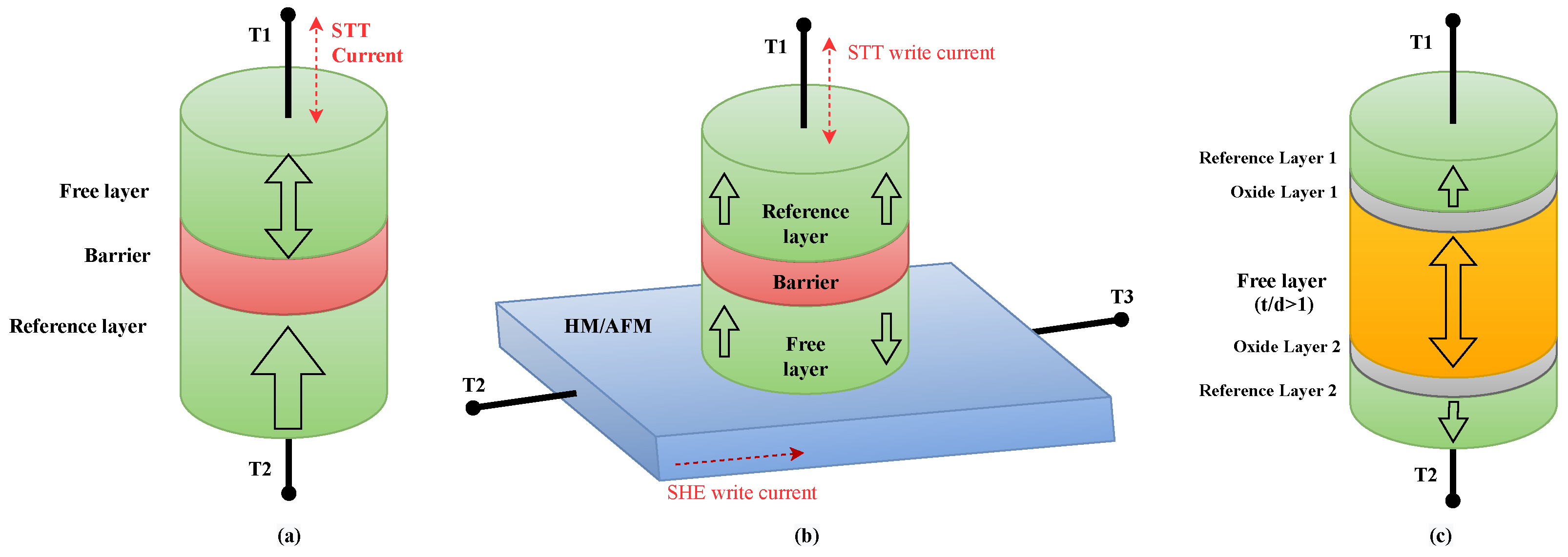
MTJs conventionally used for single-bit storage can have two (2T) or three (3T) terminals. The conventional 2T MTJ configuration with a single barrier oxide layer between two ferromagnetic layers is shown in Figure 2a. A charge current is passed between terminals T1 and T2 for switching the state of MTJ. The device structure of a 3T MTJ with an additional heavy metal (HM)/anti-ferromagnet (AFM) layer is shown in Figure 2b [20]. A charge current (SHE write) is passed through terminals T2 and T3, and a small amount of STT current is passed through T1 for switching. Figure 2c shows the s-PMA DMTJ structure [13], which consists of a top and bottom oxide layer, a free layer, and reference layers. The shape anisotropy and interfacial PMA effect favor the out-of-plane orientation of the magnetization of the storage layer. The thermal stability factor ( Δ ) is a crucial design consideration and is calculated using a single domain model [18] for an s-PMA DMTJ:
Δ = ( δ N M S 2 2 μ 0 t + K b t + K i ) π D 2 4 k B T
where K b and K i are the bulk and anisotropy energies, k B is the Boltzmann’s constant, T is the temperature, M S is the saturation magnetization, μ 0 is the magnetic permeability in free space, t and D are the free layer thickness and diameter, respectively, and δ N is the shape anisotropy coefficient between the perpendicular and in-plane anisotropy direction. A positive value of δ N indicates in-plane magnetic anisotropy (IMA), and a negative value represents the s-PMA region, which is the desired operation region. A proper selection of device dimensions is required to obtain a large value of Δ ≈ 80.

2.2. Design of LL Block Using s-PMA DMTJ

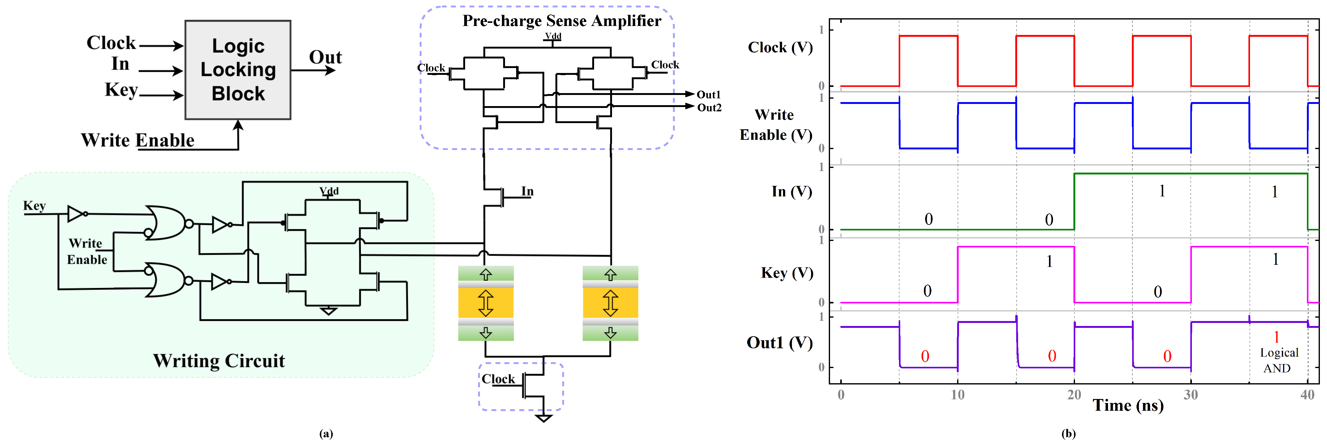
Thwarting LL attacks are essential for securing the IP of the integrated circuits [21]. The block diagram for the LL mechanism is displayed alongside the overall circuit executing the AND/NAND operation in Figure 3a. Another single layer 2T MTJ structure using the same methodology is present in [12]. The logic locking mechanism can be implemented using either output terminal from the complementary outputs Out1 and Out2. The LL block operates as a logical AND when the Input (In) and Key are applied, as shown in Figure 3b. The writing circuit, the pre-charge sense amplifier (PCSA), and other MOS transistors are from the TSMC 40nm CMOS process design kit, and the simulations are performed using the Cadence Spectre simulator. The simulation steps are 1 ps, and the temperature is set at 300 K. Both complementary outputs are precharged to Vdd through PCSA when the clock pulse is low. This is referred to as the pre-charge phase. The clock pulse is raised during the evaluation phase, and both outputs are evaluated based on the resistance offered by each branch.

3. Simulation Setup

The LL block must be evaluated for high-speed data transmission, transient performance, and tolerance to device imperfection emerging from fabrication to evaluate structural and circuit performance. The MTJ dimensions and thermal stability factor are essential design constraints to allow the shape anisotropy effect to come into play. Technology parameters such as M S , Gilbert damping coefficient, etc. are set at the default value used in the compact model as it depends on the material parameters, and only device parameters which depend on the mask and process design are changed. After executing a number of the circuit analysis techniques indicated in this section, we further evaluate the LL block in a small test circuit and compare its performance to that reported in Section 4 for various 2T MTJ structures under analogous circuit conditions.

3.1. Eye Diagram Test for Signal Integrity at High Data Rates

Eye diagram tests help keep track of signal duration, synchronization with the system clock pulse, noise effect, undershoot and overshoot, etc. The distribution of the time transitions between the low and high levels is revealed by segmenting the signal into layers placed on top of one another. This test is necessary to ascertain the LL block operation at high-speed data rates, as ICs are expected to operate at higher speeds. Significant degradation in eye analysis can be a challenge for practical applications. To adequately capture each transition, the unit interval (UI) is set at 5 ns. A centered eye diagram is created with the threshold set at 0.5 V and the eye period at 2*UI (10 ns). Utilizing the non-return to zero (NRZ) modulation approach on the LL block and test circuit, a customized eye mask is built in order to determine the effective operation range.

3.2. Transient Measurement

In order to effectively operate and reduce the additional propagation delay brought on by the insertion of such blocks in the SoC flow, LL blocks must have transient measurement analysis to guarantee that these parameters are correctly tuned. This analysis assesses several factors for the LL block and test circuit, including fall time, delay, duty cycle, RMS signal amplitude value, and numerous other transient characteristics. A significant degraded transient behavior of LL block is unsuitable for insertion in ICs as it will affect the overall performance.

3.3. Monte Carlo Simulations

While fabricating the s-PMA DMTJ, a certain amount of process variation (PV) will be present due to the presence of multi layers in the nano-pillar. Even a tiny deviation from the selected parameters can cause severe performance degradation and incorrect operation. Thus, robustness to device imperfections is a critical aspect of any practical application. To account for this effect, Monte Carlo (MC) simulations are performed with a low-discrepancy sequence (LDS) to introduce PV with a Gaussian distribution in key MTJ parameters, including TMR (±0.1), bottom oxide thickness (±0.1 nm), top oxide thickness (±0.01 nm), and free layer thickness (±0.1 nm). To assess the impact of such variation and tolerance of the LL structure, thousand times MC simulations are run on the final optimized LL block.

3.4. Spectrum Analysis

The behavior of the test circuit output is assessed using spectrum analysis and compared to other 2T MTJ structures. The spectrum data are generated using the Blackman window type method, with 1024 samples count/freq, signal bins set to 2, and harmonics set to 1. The results are summarized in Section 4.

4. Simulation Results

The design of the optimum LL block utilizing the simulation setup indicated in Section 3 is described in Section 4.1. Section 4.2 inserts the designed LL block in a test circuit to ensure that the designed LL block operates optimally and allows for uniform comparison with other 2T MTJ structures identical to it studied under similar test circuits and operating conditions.

4.1. Logic Locking Block

The simulation setup described in Section 3 is used to design and evaluate the performance of the LL block shown in Figure 3a. Based on the study, the final test circuit’s mask and process parameters are selected to be in the best design range for the LL operation of the selected s-PMA DMTJ model and to function well under the Eye diagram test and Monte Carlo simulations.

4.1.1. Parametric Sweep and Performance Evaluation

To enable a suitable selection of thermal stability and shape anisotropy effect, Figure 4 illustrates variations of critical parameters along with device dimension. A necessary transient behavior as a function of bottom oxide thickness is plotted in Figure 4a. The plot shows that better transient behavior is achieved by thin bottom oxide/layer thickness. Up until 1.18 nm, which is designated as a crucial value, good transient behavior is seen. Figure 4b displays the same trend for the Eye diagram analysis. Thus, the LL operation’s thickness must be between 0.85 and 1.18 nm. A parametric sweep of 10% is applied to test the LL block’s tolerance to changes in V d d (0.9 V). The absence of any LL block logic operation errors demonstrates the tolerance for V d d variance. The variation in MTJ resistance concerning top oxide/layer thickness, as shown in Figure 4c, is not large enough to cause a malfunction in LL operation in the range of 0 to 0.3 nm. The effect of free layer thickness (t) and diameter (D) has a very significant effect on the stability factor of the s-PMA DMTJ, as illustrated in Equation (1). The larger thermal stability factor is the desired criteria, but it requires a larger thickness, as shown in Figure 4d. A good Δ value lies in 60–100 and with D = 10 nm and t ≈ 14 nm, Δ ≈ 80 can be achieved. Critical ranges are marked in Figure 4, and the final selected MTJ dimensions are mentioned in Table 1 based on the analysis for the LL block.

4.1.2. Eye Diagram Mask and Monte Carlo Simulation

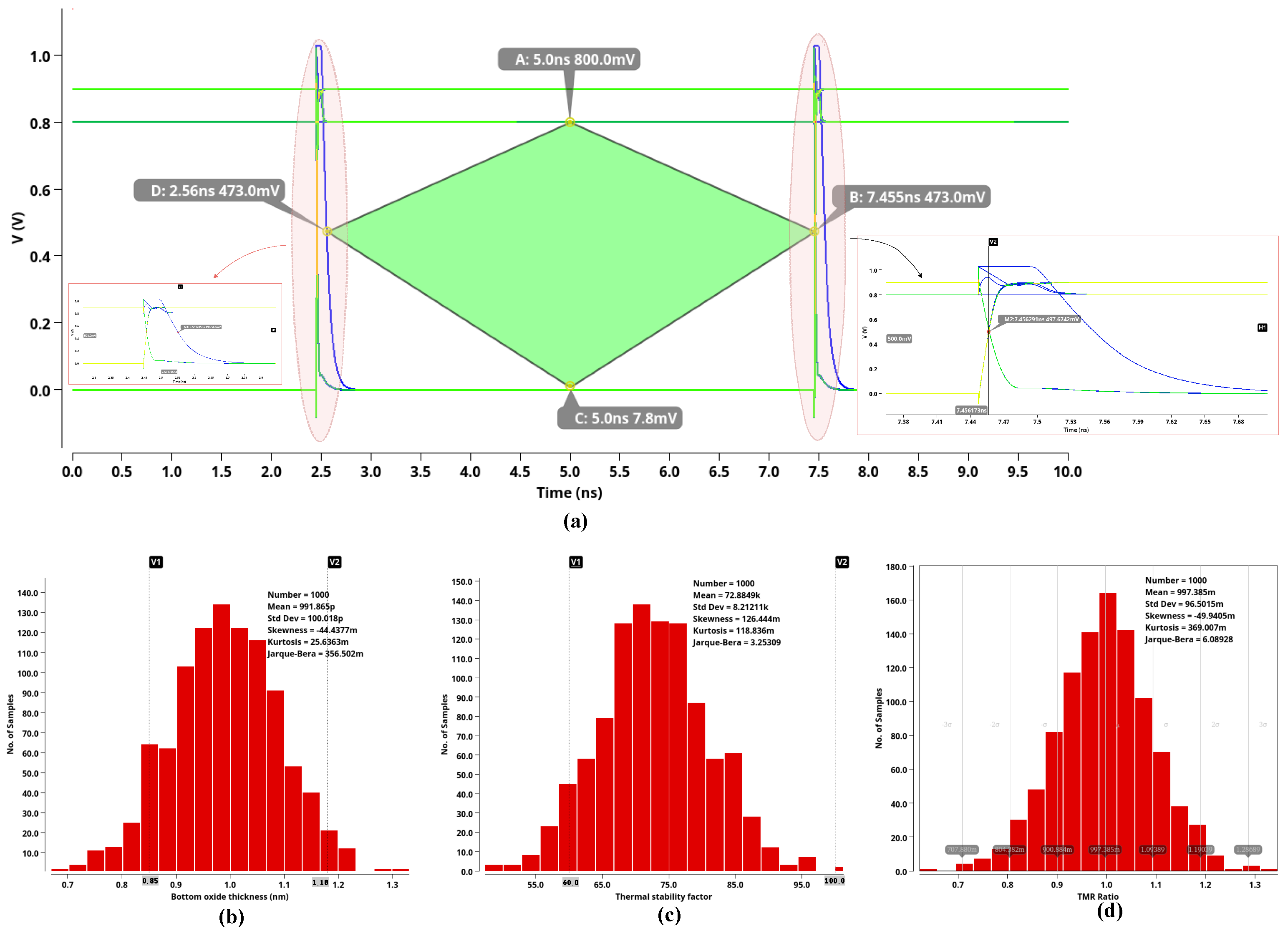
Figure 5a shows the eye diagram result for the selected values. The green mask represents pass evaluation for the high-speed operation, highlighting all four diamond-shaped masks’ vertices. Figure 5b contains 1000 times MC simulation results for variation in bottom oxide thickness and Figure 5c for a thermal stability factor. The MTJ bias-dependent TMR value variation is shown in Figure 5d to analyze the device’s tolerance based on Monte Carlo simulations for process variation. In this acceptable range, the LL block’s accuracy is 99 percent, but the block’s Eye-diagram performance and transient behavior have deteriorated for values outside of this range. As a result, our design range has enough tolerance for TMR variation and other important process variations in device characteristics.

4.2. Test Circuit

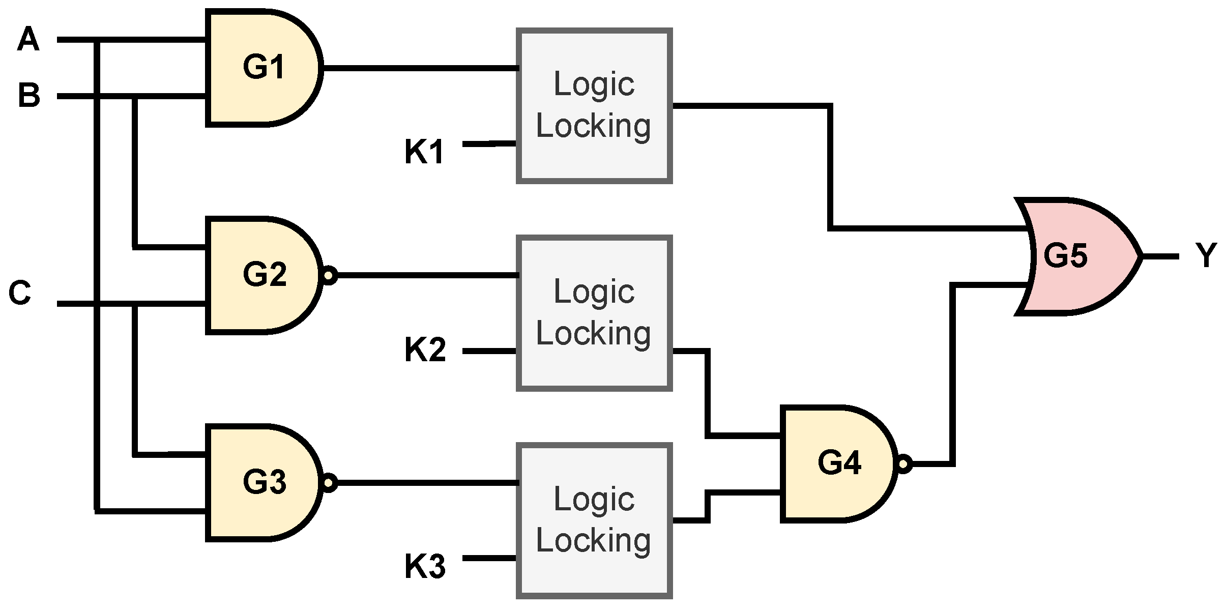
After the design of the LL block, it is inserted in a test circuit, as shown in Figure 6. The desired boolean operation is Y = A B + B C + C A under the correct key operation. Table 2 contains the data for eye diagram analysis for the output Y. The key value is marked from 0–7, where 0 represents the pattern K 1 K 2 K 3 = 000 and 7 represents K 1 K 2 K 3 = 111 , and the corresponding single bit Y value is mentioned in Table 3. The operation waveform is shown in Figure 7 for a few of the cases. For comparing the performance of s-PMA DMTJ with STT-PMA MTJ [22] and precessional voltage-controlled-magnetic-anisotropy (VCMA) STT-MTJ [23], the LL block is used in the test circuit for a general comparison for high-speed digital applications by using the same circuit condition and simulation setup mentioned in Section 3. Authors also test other 3T MTJ structures in [24] under the same test circuit conditions. As 2T structures take less area and have several other advantages over 3T structures, this work demonstrates the ability of s-PMA DMTJ to be a much better potential choice for a clever way of securing hardware using emerging devices. The simulation results show that, for high-speed data applications, s-PMA DMTJ used in this work has slightly worse results than other 2T MTJ in terms of eye width, rise time, and jitters. Table 4 and Table 5 contain the transient behavior and the spectrum analysis, respectively. Table 6 contains the overall comparison based on the simulation and thus shows the possibility of using s-PMA DMTJ for practical applications in designing the logic-locked system.

5. Security Aspect and Challenges of s-DMTJ Based LL

The LL mechanism is employed to counter several threat models in hardware security. Techniques such as reverse engineering (RE) can be deployed at various abstraction levels and includes a set of manual and semi-automated steps [25,26]. RE is a complex and destructive process that can be used in the context of LL to obtain the required netlist for IP theft. Several crucial security elements are discussed in this section in order to protect the LL system against various threat models, including algorithmic and RE attacks. It is outside the scope of the current work to describe in detail the security aspect and threat models for such new devices.

5.1. Layout Camouflaging

Layout camouflaging (LC) can increase the complexity of RE-based attacks [27]. Re-configurable logic [28] can be produced by MTJ devices, and the device’s compliance with standard cell format makes this a feasible method to add complexity to RE-based attacks. Figure 8a,b shows the layout of a CMOS NAND and AND logic gate designed in the TSMC 40 nm technology node, respectively. An RE-based attack makes it easier for the attacker to decipher the logic operation based on the layout and obtain the locked netlist. Using a machine learning-based attack in conjugation, the attacker can obtain the key values with iteration. Thus, the RE attack can make the LL mechanism vulnerable. Figure 8c shows the layout diagram of the LL block described in this work. The LL block takes up about twice as much area as a CMOS NAND gate and about 34% more area than a CMOS AND gate. The LL block, however, offers both operations simultaneously in addition to a camouflaged layout, thus providing complexity to RE-based attacks to determine the logic operation implemented by the LL block.

5.2. Output Corruption Measurements for Logic Locking

Hamming Distance (H.D.) [29] is a widely used metric for evaluating the LL system output corruption. Equation (2) describes the average H.D. between a locked circuit and the original circuit:
1 y × N I × N K i = 1 N K j = 1 N I H . D . Y L I j , K i , Y o I j × 100 %
Here, N K is the key values, each with N I input patterns, y is the output bit number, Y L is the locked output, and Y o represents the output for the original circuit. For our test circuit, the average H.D. is 25% based on Table 3 with N K = 8, N I = 8, y = 1. The ideal H.D. should be 50%, and thus the test circuit can be modified to obtain that during practical applications.
Equation (3) describes the output error rate [30], which presents the probability of erroneous bit(s) at the output vector of Y L :
1 N I × N K i = 1 N K j = 1 N I z × 100 %
where,
z = 1 , if H . D . Y L I j , K i , Y o I j 1 0 , otherwise
Equation (5) determines the output corruption coverage and accounts for the amount of propagated corruption in the output circuit:
X y × 100 %
where,
X = max H . D . Y L I j , K i , Y o I j i 1 N I , j 1 N K
With X = 1 and y = 1, the output corruption coverage is 100% for the test circuit. The ideal value for output corruption coverage is also 100%. Thus, while designing any LL circuit, output corruption measurements must be considered for better logic obfuscation. A drawback of such new devices is the need for more research into the effective design to improve output corruption performance and deceptive structure design employing the MTJ-based LL block.

5.3. Current Challenges in s-DMTJ Based LL

Even though the emerging s-PMA DMJT has several significant advantages, the designing of a deceptive LL system faces specific critical issues. Firstly, the fabrication of double barrier MTJ is challenging as stack etching is more complicated than conventional STT-MTJ [31]. Further structural improvement by using a magnetically switchable assistance layer (ASL) acting as a top perpendicular spin polarizer in a double barrier MTJ structure is described in [31]. Additionally, LL is a technique that is generally utilized even when the foundry is untrustworthy. However, to use emerging devices at the hardware level, specialist foundries must be able to create the structure depicted in Figure 1, which currently limits its applicability to some threat models. The proposed structure simulated using a Verilog A model on an EDA tool. However, for actual physical execution, several crucial factors must be ascertained. At lower technology nodes, the hardware reliability effects such as aging and TDBB [32,33] for the s-PMA DMTJ need more thorough analysis. Stray magnetic fields might make it challenging to carry out the intended operation. Therefore, methods such as magnetic shielding and process and stack optimization can improve reliability [34]. In order to find more practical applications, more research from the standpoint of LL blocks that have been actually fabricated is required. Nevertheless, this work highlights the potential use of s-PMA DMTJ as a good substitute for such logic-locking applications.

6. Conclusions

Shape anisotropy and interfacial perpendicular magnetic anisotropy effects allow the double barrier MTJ to have reduced dimension in the sub-micron regime with a high thermal stability factor Δ ≈ 80. Additionally, because no HM/AFM layers are present, they occupy less space than 3T MTJ structures and do not require an external magnetic field for switching. These substantial advantages of the s-PMA DMTJ are utilized in this study to carry out the logic locking operation with the most diminutive possible physical dimensions. The findings of Monte Carlo simulations that consider the impact of Process variation on key MTJ parameters demonstrate that the LL application is accurate and robust to such variation. In order to compare the performance and operation with other 2T MTJs of a comparable design, a test circuit is also simulated. Under similar circuit specifications, the electrical simulation shows a slight loss in the transient, spectrum, and signal integrity even with a lower area and higher thermal stability. Future studies will address performance against algorithm-based Machine learning (ML) attacks and circuit architecture to create deceptive LL approaches taking into account the effect of aging and other breakdown processes.

Author Contributions

Conceptualization, D.D.; methodology, D.D. and R.K.; software, D.D. and R.K.; validation, D.D., R.K., D.K. and Y.M.; formal analysis, D.D.; investigation, D.D., R.K. and D.K.; resources, D.K., S.A. and Y.M.; data curation, D.D. and R.K.; writing—original draft preparation, D.D. and D.K.; writing—review and editing, D.K. and S.A.; visualization, D.D. and R.K.; supervision, Y.M.; project administration, Y.M.; funding acquisition, Y.M. All authors have read and agreed to the published version of the manuscript.

Funding

This research received no external funding.

Institutional Review Board Statement

Not applicable.

Informed Consent Statement

Not applicable.

Data Availability Statement

Data sharing is not applicable to this article.

Conflicts of Interest

The authors declare no conflict of interest.

References

  1. Hu, W.; Chang, C.-H.; Sengupta, A.; Bhunia, S.; Kastner, R.; Li, H. An Overview of Hardware Security and Trust: Threats, Countermeasures, and Design Tools. IEEE Trans. Comput.-Aided Des. Integr. Circuits Syst. 2021, 40, 1010–1038. [Google Scholar] [CrossRef]
  2. Chakraborty, A.; Jayasankaran, N.G.; Liu, Y.; Rajendran, J.; Sinanoglu, O.; Srivastava, A.; Xie, Y.; Yasin, M.; Zuzak, M. Keynote: A Disquisition on Logic Locking. IEEE Trans. Comput.-Aided Des. Integr. Circuits Syst. 2020, 39, 1952–1972. [Google Scholar] [CrossRef]
  3. Khan, M.N.I.; Ghosh, S. Comprehensive Study of Security and Privacy of Emerging Non-Volatile Memories. J. Low Power Electron. Appl. 2021, 11, 36. [Google Scholar] [CrossRef]
  4. Mishra, R.; Yang, H. Emerging Spintronics Phenomena and Applications. IEEE Trans. Magn. 2021, 57, 1–34. [Google Scholar] [CrossRef]
  5. Srinivasan, S.; Sarkar, A.; Behin-Aein, B.; Datta, S. All-Spin Logic Device with Inbuilt Nonreciprocity. IEEE Trans. Magn. 2011, 47, 4026–4032. [Google Scholar] [CrossRef] [Green Version]
  6. Shreya, S.; Jain, A.; Kaushik, B.K. Computing-in-Memory Architecture Using Energy-Efficient Multilevel Voltage-Controlled Spin-Orbit Torque Device. IEEE Trans. Electron Devices 2020, 67, 1972–1979. [Google Scholar] [CrossRef]
  7. Shen, S.Q. Spintronics and spin current. AAPPS Bull. 2008, 18, 29. [Google Scholar]
  8. Ghosh, S. Spintronics and Security: Prospects, Vulnerabilities, Attack Models, and Preventions. Proc. IEEE 2016, 104, 1864–1893. [Google Scholar] [CrossRef]
  9. Onizawa, N.; Mukaida, S.; Tamakoshi, A.; Yamagata, H.; Fujita, H.; Hanyu, T. High-Throughput/Low-Energy MTJ-Based True Random Number Generator Using a Multi-Voltage/Current Converter. IEEE Trans. Very Large Scale Integr. (VLSI) Syst. 2020, 28, 2171–2181. [Google Scholar] [CrossRef]
  10. Divyanshu, D.; Kumar, R.; Khan, D.; Amara, S.; Massoud, Y. Physically Unclonable Function using GSHE driven SOT assisted p-MTJ for next generation hardware security applications. IEEE Access 2022, 10, 93029–93038. [Google Scholar] [CrossRef]
  11. Kumar, R.; Divyanshu, D.; Khan, D.; Amara, S.; Massoud, Y. Spin Orbit Torque-Assisted Magnetic Tunnel Junction-Based Hardware Trojan. Electronics 2022, 11, 1753. [Google Scholar] [CrossRef]
  12. Divyanshu, D.; Kumar, R.; Khan, D.; Amara, S.; Massoud, Y. Logic Locking Using Emerging 2T/3T Magnetic Tunnel Junctions for Hardware Security. IEEE Access 2022, 10, 102386–102395. [Google Scholar] [CrossRef]
  13. Wang, H.; Kang, W.; Zhang, Y.; Zhao, W. Modeling and Evaluation of Sub-10-nm Shape Perpendicular Magnetic Anisotropy Magnetic Tunnel Junctions. IEEE Trans. Electron Devices 2018, 65, 5537–5544. [Google Scholar] [CrossRef]
  14. Chun, K.C.; Zhao, H.; Harms, J.D.; Kim, T.-H.; Wang, J.-P.; Kim, C.H. A Scaling Roadmap and Performance Evaluation of In-Plane and Perpendicular MTJ Based STT-MRAMs for High-Density Cache Memory. IEEE J. Solid-State Circuits 2013, 48, 598–610. [Google Scholar] [CrossRef]
  15. Garzon, E.; De Rose, R.; Crupi, F.; Trojman, L.; Lanuzza, M. Assessment of STT-MRAM performance at nanoscaled technology nodes using a device-to-memory simulation framework. Microelectron. Eng. 2019, 215, 111009. [Google Scholar] [CrossRef]
  16. Wang, Z.; Zhao, W.; Deng, E.; Klein, J.O.; Chappert, C. Perpendicular-anisotropy magnetic tunnel junction switched by spin-Hall-assisted spin-transfer torque. J. Phys. D Phys. 2015, 48, 065001. [Google Scholar] [CrossRef]
  17. Zhang, K.; Zhang, D.; Wang, C.; Zeng, L.; Wang, Y.; Zhao, W. Compact Modeling and Analysis of Voltage-Gated Spin-Orbit Torque Magnetic Tunnel Junction. IEEE Access 2020, 8, 50792–50800. [Google Scholar] [CrossRef]
  18. Watanabe, K.; Jinnai, B.; Fukami, S.; Sato, H.; Ohno, H. Shape anisotropy revisited in single-digit nanometer magnetic tunnel junctions. Nat. Commun. 2018, 9, 663. [Google Scholar] [CrossRef] [Green Version]
  19. Perrissin, N.; Lequeux, S.; Strelkov, N.; Chavent, A.; Vila, L.; Buda-Prejbeanu, L.D.; Auffret, S.; Sousa, R.C.; Prejbeanu, I.L.; Dieny, B. A highly thermally stable sub-20 nm magnetic random-access memory based on perpendicular shape anisotropy. Nanoscale 2018, 10, 12187. [Google Scholar] [CrossRef] [PubMed] [Green Version]
  20. Wang, M.; Zhang, Y.; Zhao, X.; Zhao, W. Tunnel Junction with Perpendicular Magnetic Anisotropy: Status and Challenges. Micromachines 2015, 6, 1023–1045. [Google Scholar] [CrossRef] [Green Version]
  21. Limaye, N.; Kalligeros, E.; Karousos, N.; Karybali, I.G.; Sinanoglu, O. Thwarting All Logic Locking Attacks: Dishonest Oracle with Truly Random Logic Locking. IEEE Trans.-Comput.-Aided Des. Integr. Circuits Syst. 2021, 40, 1740–1753. [Google Scholar] [CrossRef]
  22. Zhang, Y.; Yan, B.; Kang, W.; Cheng, Y.; Klein, J.O.; Zhang, Y.; Chen, Y.; Zhao, W. Compact Model of Subvolume MTJ and Its Design Application at Nanoscale Technology Nodes. IEEE Trans. Electron Devices 2015, 62, 2048–2055. [Google Scholar] [CrossRef]
  23. Kang, W.; Ran, Y.; Zhang, Y.; Lv, W.; Zhao, W. Modeling and Exploration of the Voltage-Controlled Magnetic Anisotropy Effect for the Next,-Generation Low-Power and High-Speed MRAM Applications. IEEE Trans. Nanotechnol. 2017, 16, 387–395. [Google Scholar] [CrossRef]
  24. Divyanshu, D.; Kumar, R.; Khan, D.; Amara, S.; Massoud, Y. Design of VGSOT-MTJ-Based Logic Locking for High-Speed Digital Circuits. Electronics 2022, 11, 3537. [Google Scholar] [CrossRef]
  25. Azriel, L.; Ginosar, R.; Mendelson, A. Sok: An overview of algorithmic methods in IC reverse engineering. In Proceedings of the 3rd ACM Workshop on Attacks and Solutions in Hardware Security Workshop, London, UK, 15 November 2019; pp. 65–74. [Google Scholar]
  26. Subramanyan, P.; Tsiskaridze, N.; Li, W.; Gascón, A.; Tan, W.Y.; Tiwari, A.; Shankar, N.; Seshia, S.A.; Malik, S. Reverse engineering digital circuits using structural and functional analyses. IEEE Trans. Emerg. Top. Comput. 2013, 1, 63–80. [Google Scholar] [CrossRef]
  27. Rajendran, J.; Sam, M.; Sinanoglu, O.; Karri, R. Security analysis of integrated circuit camouflaging. In Proceedings of the ACM SIGSAC Conference on Computer & Communications Security, Berlin, Germany, 4–8 November 2013; pp. 709–720. [Google Scholar]
  28. Zhang, H.; Kang, W.; Wang, L.; Wang, K.L.; Zhao, W. Stateful Reconfigurable Logic via a Single-Voltage-Gated Spin Hall-Effect Driven Magnetic Tunnel Junction in a Spintronic Memory. IEEE Trans. Electron Devices 2017, 64, 4295–4301. [Google Scholar] [CrossRef]
  29. Rajendran, J.; Zhang, H.; Zhang, C.; Rose, G.S.; Pino, Y.; Sinanoglu, O.; Karri, R. Fault Analysis-Based Logic Encryption. IEEE Trans. Comput. 2015, 64, 410–424. [Google Scholar] [CrossRef]
  30. Sengupta, A.; Nabeel, M.; Limaye, N.; Ashraf, M.; Sinanoglu, O. Truly Stripping Functionality for Logic Locking: A Fault-based Perspective. IEEE Trans. Comput.-Aided Des. Integr. Circuits Syst. (TCAD) 2020, 39, 4439–4452. [Google Scholar] [CrossRef]
  31. Sanchez Hazen, D.; Teixeira, B.M.S.; Salomoni, D.; Auffret, S.; Vila, L.; Sousa, R.C.; Prejbeanu, I.L.; Buda-Prejbeanu, L.D.; Dieny, B. Real time investigation of double magnetic tunnel junction with a switchable assistance layer for high efficiency STT-MRAM. APL Mater. 2022, 10, 031104. [Google Scholar] [CrossRef]
  32. McPherson, J.W. Time dependent dielectric breakdown physics-Models revisited. Microelectron. Reliab. 2012, 52, 1753–1760. [Google Scholar] [CrossRef]
  33. Lv, H.; Leitao, D.C.; Hou, Z.; Freitas, P.P.; Cardoso, S.; Kämpfe, T.; Müller, J.; Langer, J.; Wrona, J. Barrier Breakdown Mechanism in Nano-Scale Perpendicular Magnetic Tunnel Junctions with Ultrathin MgO Barrier. AIP Adv. 2018, 8, 055908. [Google Scholar] [CrossRef]
  34. Van Beek, S.; Martens, K.; Roussel, P.; Couet, S.; Souriau, L.; Swerts, J.; Kim, W.; Rao, S.; Mertens, S.; Lin, T.; et al. Impact of Processing and Stack Optimization on the Reliability of Perpendicular STT-MRAM. In Proceedings of the 2017 IEEE International Reliability Physics Symposium (IRPS), Monterey, CA, USA, 2–6 April 2017. [Google Scholar]
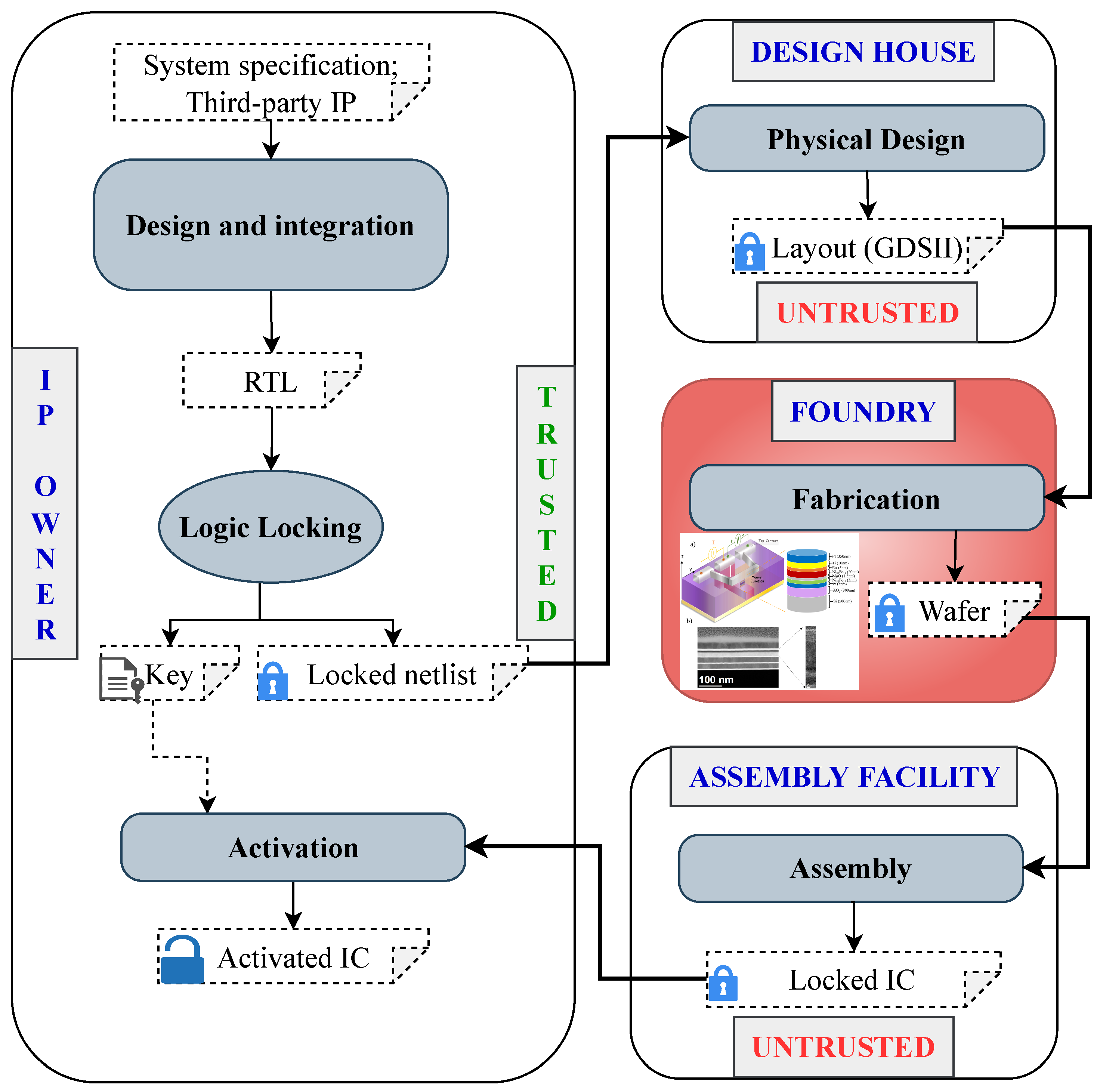
Figure 1. Overall Logic Locking mechanism in SoC design flow with trusted and untrusted entities.
Electronics 12 00479 g001
Figure 2. Typical structure of a (a) two-terminal conventional single barrier MTJ; (b) three-terminal MTJ; (c) s-PMA Double barrier MTJ.
Electronics 12 00479 g002
Figure 3. (a) Circuit and block diagram based on s-PMA DMTJ for LL mechanism; (b) output waveform for LL block performing AND operation.
Electronics 12 00479 g003
Figure 4. Variation of (a) transient parameters vs. bottom oxide thickness; (b) eye parameters vs. bottom layer thickness; (c) oxide resistance vs. top layer thickness; (d) thermal stability factor vs. free layer thickness.
Electronics 12 00479 g004
Figure 5. (a) Eye diagram test with mask; (b) Monte Carlo simulation results for variation in bottom oxide thickness; (c) Monte Carlo simulation results for variation in bottom oxide thickness; (d) introduced Variation in TMR ratio for analyzing the tolerance of the LL block.
Electronics 12 00479 g005
Figure 6. Test circuit where some of the CMOS AND logic gates are replaced by the LL block.
Electronics 12 00479 g006
Figure 7. Output Y for the test circuit under different key combinations indicating LL operation.
Electronics 12 00479 g007
Figure 8. Layout of (a) CMOS NAND logic gate; (b) CMOS AND logic gate; (c) the LL block used in this work.
Electronics 12 00479 g008
Table 1. s-PMA DMTJ parameters used for designing a logic locking block.
ParameterValue
Diameter (D)10 nm
Free Layer Thickness (t)14 nm
Top Oxide Thickness0.2 nm
Bottom Oxide Thickness1 nm
TMR Ratio at zero bias1
Damping Coefficient0.005
Saturation Magnetization ( M S )1.2 × 10 6 A/m
Spin Polarization0.57
Interfacial anisotropy density ( K i )2.2 × 10 6 KJ/m 2
Gyromagnetic Ratio ( γ )2.21 × 10 5 m/ (A.s)
Table 2. Eye diagram test analysis for signal integrity for the selected MTJ devices for High speed digital circuits’ applications.
Eye-ParametersPMA-STTPre-VCMA STTs-DMTJ
Level 0, 1: Mean290.6 nV, 1 V293.7 nV, 1 V64.36 μ V, 1 V
Level 0, 1: SD26.98 pV, 1.909 nV3.088 nV, 4.893 nV15.45 μ V, 12.54 μ V
Eye Amplitude & Height1 V, 1 V1 V, 1 V999.9 mV, 999.8 mV
Eye Width4.8 ns4.266 ns3.795 ns
Eye Rise & Fall Time4.758 ps, 7.462 ps4.687 ps, 16.18 ps1.195 ps, 127.6 ps
Random Jitter20.6 ps77.41 ps126 ps
Deterministic Jitter71.64 ps269.2 ps448.7 ps
Table 3. Truth table for all possible outcomes for s-PMA DMTJ based LL block implementing Y = AB + BC + CA.
ABCY s DMTJ
01234567
00000000000
00100000000
01000000000
01100110011
10000000000
10101010101
11000001111
11101101001
Table 4. Transient Measurements data for different 2T MTJ devices in the test circuit.
ParameterPMA STTPre-VCMAs-DMTJ
Amplitude (RMS)874.7 mV880 mV881.4 mV
Minimum Delay100.6 ps298.7 ps462.7 ps
Duty Cycle50.72%52.72%54.24%
Minimum Fall Time12.70 ps25.93 ps47.2 ps
Minimum Rise Time8.295 ps7.724 ps41.58 ps
Table 5. Spectrum Analysis data for different 2T MTJ devices in the test circuit.
ParametersPMA STTPre-VCMAs-DMTJ
ENOB−0.286 (bits)−1.159 (bits)−0.455 (bits)
SNR0.033 (dB)−5.222 (dB)−0.980 (dB)
SFDR1.009 (dBc)1.995 (dBc)0.274 (dBc)
Signal Power−7.376 (dB)−10.925 (dB)−8.095 (dB)
Noise Floor/Bin−31.441 (dB)−31.653 (dB)−31.627 (dB)
Table 6. Short Comparison with other 2T MTJs for logic locking.
ParametersPMA STTPre-VCMAs-DMTJ
MTJ areaHighHighLow
Signal IntegrityHighMediumMedium
TransientHighHighMedium
SpectrumHighMediumMedium
Thermal StabilityMediumMediumHigh
Disclaimer/Publisher’s Note: The statements, opinions and data contained in all publications are solely those of the individual author(s) and contributor(s) and not of MDPI and/or the editor(s). MDPI and/or the editor(s) disclaim responsibility for any injury to people or property resulting from any ideas, methods, instructions or products referred to in the content.