1. Introduction
A suction bucket foundation is a method used for constructing structures on the seabed. The construction process is generally divided into two stages: self-weight and suction penetration [
1,
2]. First, an empty, upturned bucket is placed at the target site. At this point, the bucket penetrates to a certain depth into the ground owing to its self-weight. This is called the self-weight penetration stage, after which the suction penetration stage is initiated. Water and air are extracted from the bucket, and the foundation is installed with a pressure difference between that of the external environment and that within the bucket [
3,
4]. The bucket penetrates to a depth where the penetration force is equal to the resistance force. By pressure adjustment and a repetition of this process, the bucket can realize the designed depth. Furthermore, the bucket can be easily removed after use by injecting water inside the bucket [
5].
The suction bucket foundation has traditionally been used to moor anchors [
2,
5]. However, it has been increasingly used in offshore construction owing to its various advantages that include applicability to most soils, except for extremely hard and soft ground; less noise than other construction methods, such as pile driving and concrete placement; less construction time; and ease of use in deep water. Recently, many studies have been conducted on enhancing foundations for offshore structures, such as offshore wind turbines [
6,
7], temporary structures for the construction of offshore bridges, and substructures of meteorological towers [
8,
9,
10].
Securing the verticality of a foundation is extremely important for safety because the superstructure built on the foundation is extremely heavy, and a tilt in the foundation can affect its stability and performance. However, bucket inclination can occur owing to the inhomogeneity of the subsea ground. For pile foundations, the verticality standard for offshore construction is 1/25 of the pile length in Hong Kong and 1/50 in Canada [
11,
12,
13]. Contrarily, there is no verticality standard for the suction bucket foundation; hence, they are usually constructed within the allowable verticality in the specification or design of the structure.
Generally, a repeated intrusion-pulling method is used to ensure verticality in the current suction bucket foundation construction process. However, this method is heavily dependent on the experience and skills of field workers; moreover, it is relatively time-consuming. To overcome this problem, various techniques have been proposed to secure the verticality of suction bucket foundations, such as adjusting the suction pressure [
14], modulating the length of the lifting cable [
13], and utilizing a tilt-sensor-based monitoring system for real-time observations during construction [
15]. However, these techniques still depend substantially on field workers’ expertise, and they are time-intensive.
In this study, we propose an automatic verticality securing system for large circular steel pipes based on a verticality monitoring system. The proposed system incorporates a monitoring component that provides real-time data on pipe alignment and an automatic lifting cable control system that automatically adjusts the length of the lifting cable to maintain perpendicularity. The use of this system in actual suction bucket foundation construction in a real sea environment can ensure accurate speedy construction, guaranteeing the safety of the structure that is built on the foundation. The remainder of this study is organized as follows:
Section 2 presents the detailed design of the proposed system.
Section 3 describes the implementation of the verticality monitoring system and time delay of the proposed system.
Section 4 explains the automatic cable control system for controlling the lifting cable.
Section 5 presents the experimental results. Finally,
Section 6 concludes the study.
2. Design of Automatic Verticality Securing System
The existing verticality correction technique using lifting cable tension is performed by field workers who adjust the lifting cable length based on the tilt of the circular steel pipe. Hence, this method is subjective as it depends on the operator’s experience, and verticality is not precise. In this study, we aim to implement an automatic verticality securing system that can quickly and precisely secure perpendicularity, regardless of the worker’s skill level, during the construction of the suction bucket foundation. Therefore, a system comprising a verticality monitoring system and an automatic lifting cable control system for large circular steel pipes was considered (
Figure 1).
The verticality monitoring system provides verticality information to field workers such that they can monitor the bucket foundation construction conditions. Verticality information comprises the roll/pitch/yaw of the circular steel pipe and upper structure and the relative displacement and connection status between the upper structure and circular steel pipe. The system was designed to be highly scalable such that it can be quickly modified to meet various requirements. Moreover, it was designed so that the tilt origin (0°) could be set as required. Therefore, precise monitoring was possible by setting the tilt origin using an inclinometer. The data collected from the verticality monitoring system were transmitted to the controller of the lifting cable control system.
The automatic lifting cable control system was designed to separately adjust the lifting cable length based on the tilt information received from the verticality monitoring system. Generally, the cable length could be adjusted using winches and actuators. In this study, we designed the system to adjust the cable length using an actuator, considering the cost and tilt of the foundation that occurs during actual construction. The proposed system adjusts cables at locations where verticality correction is required, without changing the existing suction pile penetration construction process. Specifically, individually adjusting the length of the cable based on the verticality status resulted in the generation of eccentricity due to the difference in cable tension, which was corrected to ensure the verticality of the bucket during pile penetration. The proposed verticality monitoring system, available with either the automatic lifting cable or as a standalone solution, provides significant support to field engineers working on construction sites. In contrast to the labor-intensive manual methods influenced by workmanship, our system ensures real-time monitoring of the bucket’s verticality and automatically maintains its vertical alignment. Despite the sensor featuring internal calibration algorithms without explicit mentions of a calibration process in their datasheet, ensuring reliability may necessitate calibration and/or system overhaul. Notably, the inclination sensor is a cost-effective component, and preparing a replacement part poses minimal logistical challenges. Furthermore, the process of replacing a sensor or conducting an overhaul of this system does not require a substantial amount of time or specialized resources. Consequently, the proposed system eliminates the need for a highly skilled operator in monitoring and securing a pipe. This results in tangible benefits in terms of time efficiency, safety, and cost-effectiveness.
Offshore foundations are generally installed on the seabed using a crane on a barge ship. In a barge ship environment, the data transmission distance is relatively short, and there are few obstacles; this enables the use of wireless communications. Accordingly, wireless or wired communications can be used for foundation construction monitoring. Our system was designed to use high-speed wire communication to transmit and receive data for real-time monitoring. However, we adopted wireless communication to transmit data to field workers, considering their frequent movements. Furthermore, we used the TCP/IP protocol to ensure data availability because it has a retransmission function during data communication.
3. Verticality Monitoring System
3.1. Implementation of Verticality Monitoring System
The verticality monitoring system included a sensor, an embedded controller, and a display program. For data reliability, multiple sensors can be used, and the data collected from homogeneous or heterogeneous sensors can be fused to provide different levels of information. In this study, an MTLT105D-R sensor from ACEINNA (Tewksbury, MA, USA) was adopted because measuring the slope of at least two axes is required to monitor the verticality of the foundation. The MTLT105D-R sensor measures the pitch and roll axes at a frequency of 50 Hz and transmits the data through an RS-232 communication system. The sensor is watertight to prevent damage from the exposure to seawater in a marine environment.
The embedded controller receives data from various sensors, preprocesses the collected data, and transmits the verticality information of the circular steel pipe using wired/wireless communication. For efficient data collection and scalability, the verticality monitoring system was implemented using the APAX-5580-473AE from ADVANTECH (Taipei, Taiwan), which can be equipped with various sensors as required. The detailed specifications of the APAX-5580-473AE are listed in
Table 1.
The APAX-5580-473AE has various ports for collecting UART, analog, and digital signals; additional ports can easily be added using expansion slots. The data collected by the sensors were calibrated in an APAX-5580-473AE using a Kalman filter and then sent to the display program. The data were transmitted through an internal network using a wireless router because the communication infrastructure is generally inadequate in maritime construction environments. Long-range Wi-Fi was used for efficient data communication between the embedded controller and the display program; therefore, the APAX-5580-473AE was equipped with a Wi-Fi receiver. Additionally, the embedded controller, including the sensor, was packed in a box along with a lithium-ion battery. The battery can be selected based on its working time. The implemented sensor and embedded controller components are shown in
Figure 2.
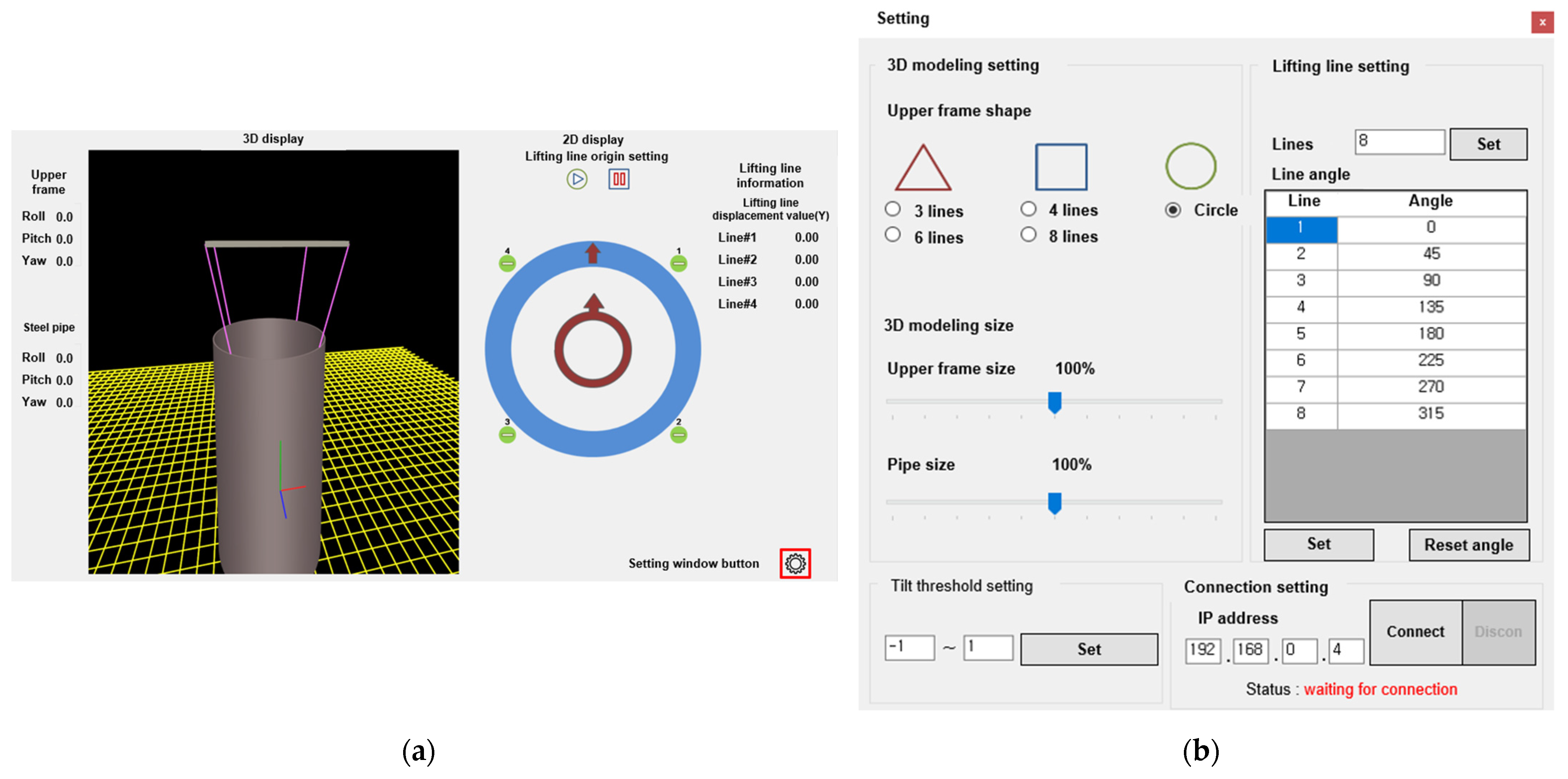
The display program receives the verticality information of the foundation from the embedded controller and presents it in an intuitive 3D display. The display comprises the upper frame and lower steel pipe posture information, 3D and 2D display screens, lifting line information, and window button setting (
Figure 3). Only roll and pitch information is required to monitor verticality. However, we implemented a display program that can display roll, pitch, and yaw, because the program can be implemented simply by changing only the system software code in the embedded controller if the yaw value is required. The 3D display screen shows a real-time 3D animation of the status of the upper frame and the verticality of the lower steel pipe. The animation can be zoomed in and out, and rotated for more detailed information. The 2D display screen was a two-dimensional flat screen showing a circular steel pipe. If the verticality exceeds the threshold, the user can intuitively understand the direction and degree of tilt of the steel pipe by changing the color of the indicators. The lifting line information displays the height of each lifting line from the initial reference value. This facilitates accurate measurements and analysis by enabling a numerical calculation of the displacement for the entire lifting line.
The setting window can be accessed by clicking a button at the bottom right of the main screen. As shown in
Figure 3, it consists of a 3D modeling setting window, a tilt threshold setting window, a lifting line setting window, and a connection setting window. The 3D modeling setting window enables the selection of the shape of the upper frame and the number of lifting lines based on the construction type; it also enables the adjustment of the size of the 3D model of the steel pipe. The tilt threshold setting window can set the limit of the allowable tilt range of the steel pipe depending on the purpose of construction. The number of lifting lines and angles can be set in the lifting line setting window. The user can connect to the embedded board with the system software to measure the verticality information by inputting the IP address in the connection setting window. The verticality information is displayed in the display program upon a successful connection.
3.2. Time Delay of Verticality Monitoring System
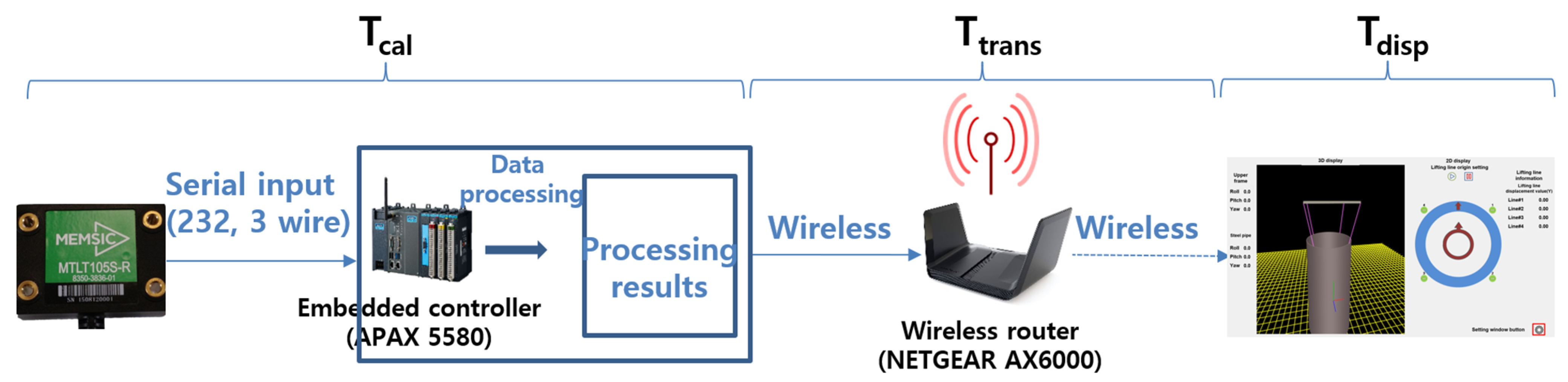
To effectively apply the proposed monitoring system to a real foundation construction environment, the system should display the verticality information in real time. In this section, we estimate the time delay for each part to verify that the verticality monitoring system satisfies real-time requirements. The data display latency of our monitoring system comprises data calculation, data transfer, and data display latencies (
Figure 4). The total time delay for data display is given by Equation (1), the latency for calculating verticality data is given by Equation (2), the latency for transferring data to the display program is given by Equation (3), and the latency for display on the monitor device is given by Equation (4).
where
denote the data calculation, transfer, and display latencies, respectively.
where
denote the sensor, h/w, and controller application latencies, respectively.
where
denotes the (OS) protocol stack latency of the embedded board,
denotes the h/w medium latency, and
denotes the OS protocol stack latency of the monitoring device.
where
denotes the GUI (Graphical User Interface) application latency and
denotes the monitoring device latency.
, which includes , , and , is the latency from sensing raw verticality data for processing data on the embedded board. is the latency at which the sensor measures the raw verticality data. is the latency for the sensed data to be transmitted to the controller using the hardware line, which is less than 1 ps. The sensor used in our system operated at 50 Hz; therefore, it could read data every 20 ms. denotes the latency resulting from processing data in the embedded controller.
, which includes , , and , is the latency required to transfer the processed data from the embedded controller to the monitoring device. and represent the latencies required to process the transmitted and received data in the OS, respectively. indicates the latency for transmitting the processed data from the embedded controller to the monitoring device. The average transmission delay measured ten times by the ping command was approximately 11.8 ms in the Wi-Fi environment.
, including and , is the latency to display verticality information in the monitoring device. indicates the latency required to operate the GUI application on the monitoring device, whereas is the time delay for the monitor to display the data, which is approximately 16 ms, because most monitors currently operate at more than 60 Hz. The APAX 5580-473AE has CPUs operating at 1.7 GHz, and the clock speed of the current CPUs used in laptops exceed 2.0 GHz. Because our system can be implemented with a simple code, negligible latency occurs when running the application, including and , and the OS code, including and . Consequently, the proposed verticality monitoring system takes approximately 48.8 ms from the data acquisition to the verticality information display and can operate in real time.
4. Automatic Lifting Cable Control System
The automatic lifting cable control system used to individually adjust the cable length consists of a hydraulic actuator, a hydraulic pump system for operating the hydraulic actuator, a relay circuit to turn the actuator switch on and off, a controller to control the relay circuit, and a serial communication circuit to receive data from the monitoring system (
Figure 5). Three factors were considered when implementing an automatic lifting cable control system using an actuator. First, it should be easy to connect the actuator to a lifting cable. Second, it should be possible to control actuators mounted on multiple lifting cables connected to a circular steel pipe. Third, automatic verticality control should be possible.
The actuator connection part uses a pin type that can be connected to the frame, wire, and lifting lug, and it can be connected to the shackle, which is used in the connection part when lifting offshore structures. Generally, because four lifting cables are widely used for lifting large circular steel pipes, we implemented an individual cable control by connecting four actuators to a hydraulic pump system. The stroke of the actuator was set to 8 cm because the maximum penetration depth was approximately 8 cm in the model circular steel pipe environment, which had a diameter of 30 cm and a length of 20 cm.
The controller of the lifting cable control system operates the actuator according to a specific protocol, as shown in
Table 2. The string “
$KIOST” was set as the STX (Start of TexT) to indicate the start of the packet, and “,” was used as a delimiter. The up/down buttons of the four actuators are each classified by solid-state relay (SSR); they are set to “1” when they have to be turned on, and they are set to “0” when they have to be turned off. The ETX (End of TexT) uses the “*” character to signal the end of a packet, and an XOR checksum is added to the last for the reliable communication of the packet. For example, when transmitting “
$KIOST,1,0,0,0,0,0,0,0*4B”, Actuator 1 rises, and all other actuators stop.
The actuator can be automatically controlled based on the data from the verticality monitoring system by connecting the verticality monitoring system to the actuator control system through a serial interface. In addition, each actuator can be manually controlled through the up/down buttons in the GUI program. A program for automatically controlling the actuator was implemented using a simple algorithm. First, it receives verticality information from the verticality-monitoring system every second. It then checks whether the verticality is within the threshold and adjusts the length of the lifting cable by controlling a pair of diagonally positioned actuators in opposite directions. The program repeatedly adjusts the actuator length until the bucket tilt is within the threshold.
5. Model and Testbed Experimental Results
5.1. Model Experiment to Demonstrate Automatic Lifting Cable Control System
The suction bucket foundation method does not have vertical standards. However, they should be constructed within an allowable verticality provided in the specifications or letter of construction design [
17,
18,
19,
20].
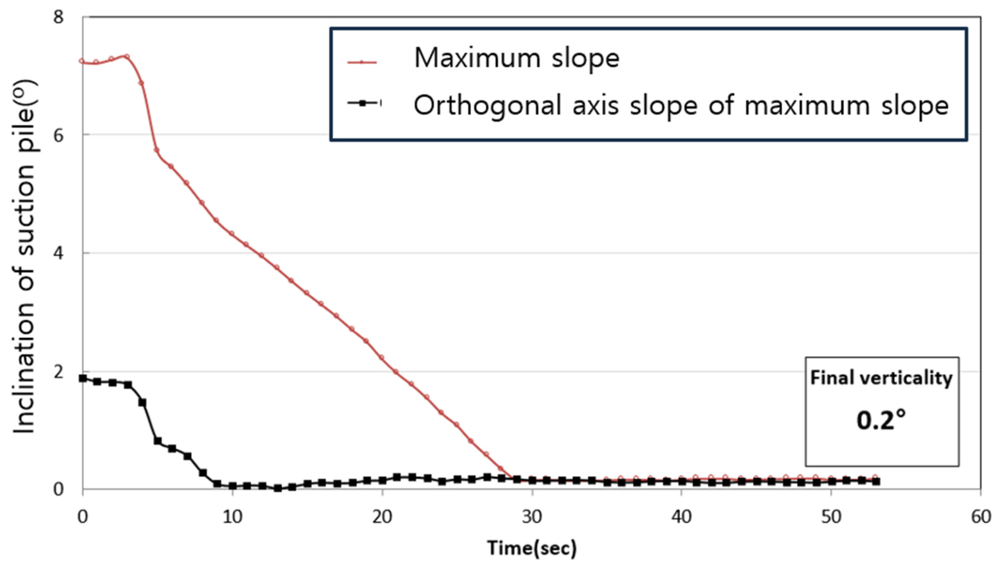
Figure 6 shows an indoor model experiment of suction bucket penetration to demonstrate the automatic lifting cable control system. The model suction bucket had a diameter of 30 cm and length of 20 cm. The soil box size is 80 cm × 80 cm × 80 cm. Standard sand was placed inside the soil box to a height of 40 cm; the soil box was then filled with water to a depth of 30 cm. Actuators were installed at four points on the top plate, and a two-axis tilt sensor was installed to measure the tilt. To enable effective penetration, we first forced the model suction bucket approximately 10 cm into the ground. Subsequently, suction penetration was performed using an automatic lifting cable control system. The verticality of the bucket was confirmed by operating the piston of the actuator based on the tilt state.
Figure 7 accurately illustrates the experimental sequence. Initially, a significant inclination of the suction pile was observed, but it gradually diminished through the process of suction penetration. The proposed system calibrated the verticality from 0.6° before suction penetration to 0.2° after penetration.
5.2. Testbed Experiment to Demonstrate Monitoring System
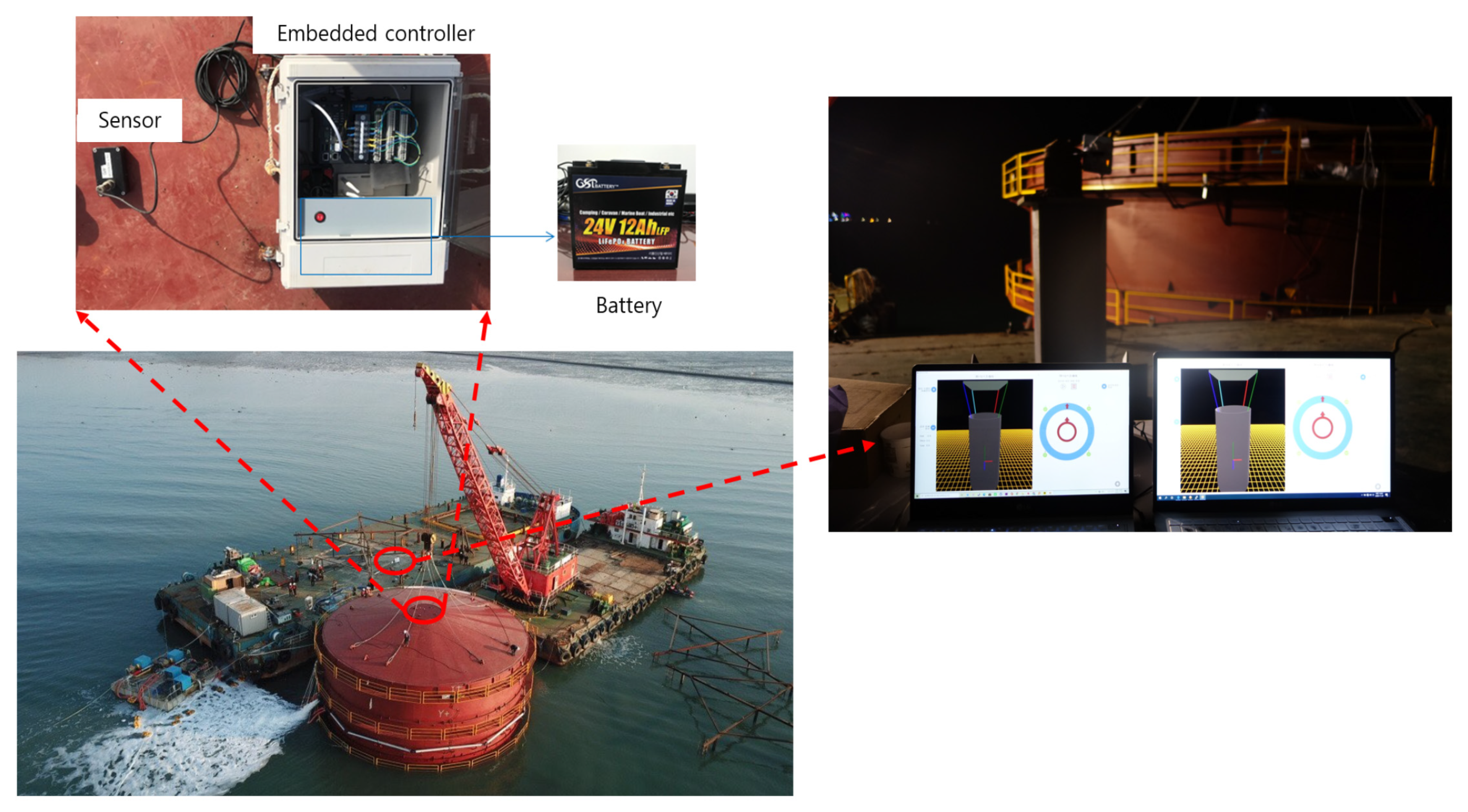
To demonstrate the verticality of the monitoring system, it was applied to the testbed of a suction bucket foundation construction performed at Jeongok Port, Gyeonggi-do, Republic of Korea in November 2020 (
Figure 8). The circular steel pipe used in the test had a 5 m diameter; it was 9.5 m long and weighed approximately 50 tons. A tilt sensor and embedded controller were installed on top of the circular steel pipe, and a 24 V, 12 Ah Li-ion iron phosphate (LiFePO
4) battery was installed to enable operation for approximately 10 h, considering the daily working time. Moreover, we used a wireless AP for data communication between the embedded controller and monitoring device, considering the poor communication infrastructure of the marine environment, and used two laptops for monitoring. The results of the testbed experiment confirmed that the proposed monitoring system displayed verticality information on the two monitoring devices in real time.
6. Conclusions
In this study, we propose an automatic verticality securing system for large circular steel pipes based on a verticality monitoring system. The proposed system consists of a real-time monitoring system that provides real-time data on the pipe’s alignment and an actuator control module that automatically adjusts the length of the lifting cable to secure verticality. The verticality monitoring system minimizes verticality errors by setting the origin of the verticality when the sensor is horizontal. Furthermore, it can be used in various fields that require precise verticality, such as bridge construction, in addition to controlling the verticality of steel pipes, because it offers various adjustable options based on the construction type. The actuator control module can quickly secure verticality compared to existing techniques because it automatically adjusts the length of the lifting cable according to the tilt state. Furthermore, our system can be easily adapted to existing construction sites for suction bucket foundations because it adjusts cables at locations where a verticality correction is required without changing the existing suction pile penetration construction process. In order to assess the effectiveness of the proposed system, we performed rigorous testing utilizing an automatic lifting cable control system integrated with a suction bucket model. The proposed system operates in real time and has been demonstrated to secure a precise verticality of less than 0.2° in model experiments. Additionally, we demonstrated that the verticality monitoring system is effectively applicable to actual construction sites by applying it to a real testbed for suction bucket foundation construction. In the future, our goal is to validate its reliability by implementing the suction bucket foundation in a real sea environment. This will involve addressing sensor calibration issues. Regardless of the chosen calibration frequency, conducting a thorough reliability study is crucial, as the calibration process can potentially disrupt the overall construction schedule. Moreover, we aim to quantitatively analyze the limitations of the system. The capability of the proposed system is largely dependent on the site scale and construction period. This is because the system’s availability relies on factors such as wireless communication range, time delay, battery capacity, and the size of the fusible actuator.
Author Contributions
Conceptualization, S.K. and M.O.; methodology, S.K. and S.B.; software, S.K. and S.B.; validation, H.P. and S.K.; formal analysis, H.P.; investigation, S.K., H.P. and S.B.; data curation, H.P.; writing—original draft preparation, S.K.; writing—review and editing, S.B.; visualization, H.P.; supervision, S.B.; project administration, M.O.; funding acquisition, S.B. All authors have read and agreed to the published version of the manuscript.
Funding
This research was supported by the Korea Institute of Marine Science and Technology Promotion and was funded by the Ministry of Oceans and Fisheries (RS-2021-KS211508).
Data Availability Statement
The data used to support the findings of this study are included in the article.
Conflicts of Interest
The authors declare no conflict of interest.
References
- Bang, S.; Preber, T.; Cho, Y.; Thomason, J.; Karnoski, S.R.; Taylor, R.J. Suction piles for mooring of mobile offshore bases. Mar. Struct. 2000, 13, 367–382. [Google Scholar] [CrossRef]
- Hogervorst, J.R. Field trials with large diameter suction piles. In Proceedings of the Offshore Technology Conference, Houston, TX, USA, 5–8 May 1980. [Google Scholar]
- Houlsby, G.T.; Ibsen, L.B.; Byrne, B.W. Suction caissons for wind turbines. In Frontiers in Offshore Geotechnics: ISFOG; Taylor & Francis Group: London, UK, 2005; pp. 75–94. [Google Scholar]
- LeBlanc, C.; Houlsby, G.T.; Byrne, B.W. Response of stiff piles in sand to long term cyclic loading. Geotechnique 2010, 60, 79–90. [Google Scholar] [CrossRef]
- Senpere, D.; Auvergne, G.A. Suction Anchor Piles—A Proven Alternative to Driving or Drilling. In Proceedings of the Offshore Technology Conference, Houston, TX, USA, 3–6 May 1982. [Google Scholar]
- Wang, X.; Xu, Y.; Xiangwu, Z. Seismic centrifuge modelling of suction bucket foundation for offshore wind turbine. Renew. Energy 2017, 114, 1013–1022. [Google Scholar] [CrossRef]
- Ryu, M.S.; Lee, J.S.; Kwag, D.J.; Seo, Y.H. Verification of tripod suction pile applicability through dynamic characteristic analysis of offshore wind turbine at each installation stage. J. Wind Energy 2019, 10, 12–21. [Google Scholar]
- Kim, B.; Kim, Y.; Jin, B.; Bae, K.; Youn, H. Numerical analysis on tilting control of suction pile for offshore wind power. J. Korean Geo-Environ. Soc. 2016, 17, 5–12. [Google Scholar]
- Kwag, D.; Ryu, M.; Kwon, O.; Bang, S. Design and installation of meteorological towers with tripod suction piles for offshore wind farms. In Proceedings of the ISOPE International Ocean and Polar Engineering Conference, Busan, Republic of Korea, 15–20 June 2014. [Google Scholar]
- Ryu, M.S.; Lee, J.S.; Kwag, D.J.; Bang, S. Comparison of two meteorological tower foundations for off-shore wind turbines. In Proceedings of the ISOPE International Ocean and Polar Engineering Conference, Rhodes, Greece, 26 June–1 July 2016. [Google Scholar]
- Houlsby, G.T.; Byrne, B.W. Suction caisson foundations for offshore wind turbines and anemometer masts. Wind Eng. 2000, 24, 249–255. [Google Scholar] [CrossRef]
- Ministry of Land, Infrastructure, and Transport (MOLIT). Development of Erection Method for Marine Bridge Foundations; MOLIT: Sejong, Republic of Korea, 2015. [Google Scholar]
- Park, H.; Oh, M.; Kim, S.; Han, T.; Baek, S. Model tests on verticality correction using individual length control method for lifting cable during suction pile penetration. J. Korean Soc. Hazard Mitig. 2019, 19, 217–223. [Google Scholar] [CrossRef]
- Kim, Y.S.; Bae, K.T.; Lee, J.P.; Joung, J.W.; Choo, Y.W. Model tests for tiling control of suction bucket foundation for offshore wind turbin. J. Korean Soc. Hazard. Mitig. 2017, 17, 207–218. [Google Scholar] [CrossRef]
- Koo, Sungmin; Park, Haeyong; Oh, Myounghak; Baek, S. Verticality 3D Monitoring System for the Large Circular Steel Pipe. J. Korea Acad.-Ind. Coop. Soc. 2020, 21, 870–877. [Google Scholar]
- APAX-5580 User Manual. Available online: http://advdownload.advantech.com/productfile/Downloadfile4/1-1JA3U71/APAX-5580_User_Manual_ed.1-FINAL.pdf (accessed on 3 August 2020).
- Korea Ocean Research & Development Institute (KORDI). Suction Foundation Structure Technique Manual; KORDI: Goyang-si, Republic of Korea, 2010. [Google Scholar]
- Kim, Y.S.; Jang, Y.S. Analysis of load capacity and deformation behavior of suction pile installed in sand. J. Korean Geotech. Soc. 2011, 27, 27–37. [Google Scholar] [CrossRef]
- Lee, J.H.; Kim, D.W.; Chung, M.K.; Kwak, K.S.; Jung, Y.H. Numerical analysis of the suction pile behavior with different lateral loading locations. J. Korean Geotech. Soc. 2011, 27, 67–76. [Google Scholar] [CrossRef]
- Wang, X.; Zeng, X.; Li, J.; Yang, X.; Wang, H. A review on recent advancements of substructures for offshore wind turbines. Energy Convers. Manag. 2018, 158, 103–119. [Google Scholar] [CrossRef]
| Disclaimer/Publisher’s Note: The statements, opinions and data contained in all publications are solely those of the individual author(s) and contributor(s) and not of MDPI and/or the editor(s). MDPI and/or the editor(s) disclaim responsibility for any injury to people or property resulting from any ideas, methods, instructions or products referred to in the content. |
© 2023 by the authors. Licensee MDPI, Basel, Switzerland. This article is an open access article distributed under the terms and conditions of the Creative Commons Attribution (CC BY) license (https://creativecommons.org/licenses/by/4.0/).


