1. Introduction
The advent of metasurfaced reverberation chambers (MRCs) signifies a pivotal advancement in the field of electromagnetic testing and microwave technology. This innovative approach revolutionizes the design and functionality of traditional reverberation chambers (RCs), ushering in a new era of electromagnetic wave manipulation [
1]. Introduced by Sun et al. in 2018, this concept integrates metasurfaces—comprising two-dimensional arrays of artificial structures—into RCs. These metasurfaces enable unprecedented control over electromagnetic wave properties, including phase, amplitude, and direction, thus significantly enhancing RC performance metrics. Understanding the evolution of reverberation chambers is crucial to appreciate the significance of MRCs. Historically, RCs have played a vital role in assessing the electromagnetic compatibility and performance of electronic devices. The integration of metasurfaces marks a technological leap, offering enhanced precision and capabilities. This paper endeavors to bridge the theoretical advancements with practical applications in electromagnetic testing.
The incorporation of coding diffusion metasurfaces into RCs represents a major breakthrough. Simulations have shown that these metasurfaces could potentially replace mechanical stirrers, leading to an expanded testable volume and more uniform electromagnetic fields [
2]. This development is especially critical for electromagnetic compatibility testing, ensuring devices function reliably in varied electromagnetic environments. Our research explores the impact of these metasurfaces on key RC performance metrics such as mode density, field uniformity, and the lowest usable frequency (LUF). Investigating various coding metasurface stirrers has yielded valuable insights into their efficiencies and practical applications.
This paper experimentally validates the MRC concept using a 1-bit random coding metasurfaced stirrer, designed as an alternative to traditional metallic stirrers in an RC [
3]. We conduct a comparative analysis of this novel MRC against conventional RCs, focusing on several critical performance matrices. These include the Q factor, standard deviation, angle autocorrelation, average K factor, total scattering cross section (TSCS), and the enhanced back scattering coefficient (eb) [
4,
5]. These matrices are crucial for evaluating the operational effectiveness of the chamber, as illustrated below.
The Q factor in a reverberation chamber (RC) is pivotal as it quantifies the efficiency of energy storage versus dissipation within the chamber. A higher Q factor typically suggests an environment with more resonance, enhancing both intensity and uniformity of the electromagnetic field. However, maintaining a delicate balance is crucial, as excessive Q can result in non-uniform field distribution and behavior that depends on frequency [
6,
7,
8].
Field uniformity and test volume are critical for ensuring accurate and reliable measurements within an RC. Uniform electromagnetic fields ensure consistent exposure across the test volume, which is essential for valid testing of devices and materials. Expanding the test volume without affecting field uniformity allows for accommodating larger or multiple test subjects, thus increasing chamber versatility [
9].
Angle autocorrelation of the stirrer is a measure of how effectively the stirrer can randomize the electromagnetic field within the chamber. A lower autocorrelation suggests better randomization, leading to more uniform field distribution. The configuration details of the setup, which highlight the strategic positioning and functioning of each stirrer within the chamber, are comprehensively outlined in Ref. [
10]. The meticulous arrangement of this setup played a pivotal role in maintaining stable environmental conditions throughout the experimental proceedings. The K factor and TSCS serve as indicators of the chamber ability to foster a rich multipath environment. The K factor evaluates the equilibrium between direct and reflected power, whereas TSCS quantifies the scattering efficiency of energy within the chamber [
11,
12].
The enhanced back scattering effect, a universal phenomenon observed in various wave types including electromagnetic and acoustic waves, plays a pivotal role in reverberation chambers [
13]. This effect is not only crucial for characterizing the performance of reverberation chambers [
14] but also significantly impacts the measurement of antenna radiation efficiency [
15,
16].
Building on these insights, our paper presents a comprehensive validation of the MRC concept. We detail the design and implementation of a 1-bit random coding metasurfaced stirrer in
Section 2 and outline the system configurations in
Section 3.
Section 4, the heart of our research, meticulously evaluates key performance indicators, illuminating the impact of the metasurfaced stirrer on RC applications. Finally,
Section 5 offers an extensive summary of our findings, emphasizing the transformative potential of the metasurfaced stirrer in enhancing reverberation chamber performance and its broader implications for future developments in electromagnetic testing and microwave technology.
2. Design of the 1-Bit Random Coding Metasurface Stirrer
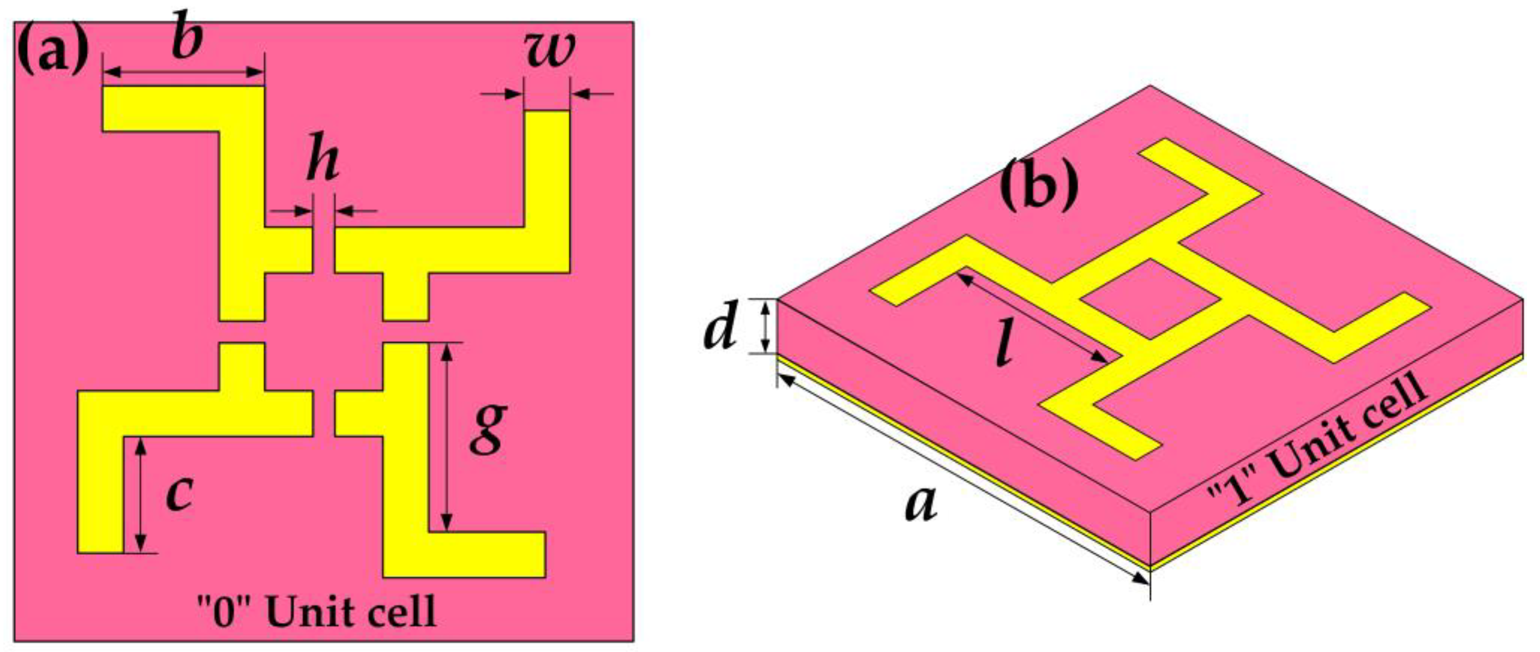
This section elucidates the design intricacies of the 1-bit random coding metasurfaced stirrer, a critical element in our research. The unit cell of the stirrer, as illustrated in
Figure 1, features a sophisticated structural design. The intermediate dielectric layer, highlighted in pink, is composed of a lossy F4B-2 substrate with a relative permittivity (ε
r) of 2.65 and a loss tangent (tan δ) of 0.001. The top layer of the unit cell, depicted in yellow, is metallized, while its bottom layer consists of a metallic film, optimizing the electromagnetic response.
The geometric parameters of the unit cell are meticulously chosen to ensure desired performance. These parameters include a breadth (b) of 7.5 mm, a length (c) of 5.1 mm, a gap (g) of 7.5 mm, and a strip length (l) of 10.5 mm. The width of the metallic strips is set at 2.4 mm (w), with a periodicity (a) of 30 mm. The thickness of the substrate (d) is 10 mm, providing both structural stability and consistent electromagnetic properties.
In its 1-bit configuration, the unit cell adopts two distinct states, “0” and “1”, differentiated by the presence or absence of a gap. A gap (
h) of 0.8 mm indicates the “0” state, while a gapless structure (
h = 0 mm) signifies the “1” state.
Figure 2 presents the 1-bit random coding sequence, derived from a specialized optimization algorithm for the metasurface, along with the phase distribution of the unit cells, shedding light on their electromagnetic characteristics.
The physical embodiment of the 1-bit random coding metasurface stirrer is displayed in
Figure 3. Designed with a circular shape and a radius (
Rm) of 255 mm, this stirrer not only enhances stirring efficiency within the reverberation chamber but also meets the structural demands for effective electromagnetic field manipulation.
To analyze the scattering characteristics of the stirrers, we initially conducted simulations of their far-field patterns using CST Microwave Studio® (CST China Ltd., Nanjing, China). These simulations were pivotal in understanding the stirrers’ electromagnetic interactions within the reverberation chamber, providing a foundation for the subsequent experimental investigations.
3. Advanced Measurement Setup in the Metasurfaced Reverberation Chamber
In the theoretical framework of our study on the metasurfaced reverberation chamber (MRC), we incorporate a pivotal mathematical model, the general coupled cavities model, as detailed on page 331 of Ref. [
17]. This model conceptualizes the MRC as a series of interconnected cavities, each contributing uniquely to the electromagnetic environment of the chamber. By applying this model, we can predict the statistical distribution of electromagnetic fields within the MRC, enhancing our understanding of its performance compared to traditional reverberation chambers.
Furthermore, to analyze the impact of the metasurface stirrer on the electromagnetic field distribution, we refer to the modal cell definition and stirrer impact model (page 149 of Ref. [
17]). This model provides a quantitative framework to evaluate how design of the stirrer influences field uniformity within the MRC. It allows us to calculate the mean-square value of the electric field, offering a metric to assess spatial uniformity. This integration of mathematical modeling into our analysis not only strengthens the theoretical underpinnings of our research but also guides future design optimizations for enhanced performance of the MRC.
The experimental setup, as illustrated in
Figure 4, plays a crucial role in validating the efficacy of the metasurfaced reverberation chamber (MRC). The reverberation chamber (RC) utilized in our experiments operates with a lowest usable frequency (LUF) of approximately 1 GHz, aligning with standard frequencies used in electromagnetic compatibility testing.
- (a)
Antenna Configuration and Network Analysis: The system employs wideband dipole antennas, identical to those validated in previous studies [
17], ensuring consistency and comparability in our measurements. These antennas are connected to a high-precision vector network analyzer (VNA, model AV3620), facilitating the accurate capture of S-parameters across a broad frequency range. The choice of a VNA model AV3620 is particularly significant due to its enhanced sensitivity and accuracy in measuring complex transmission and reflection parameters, crucial for assessing the electromagnetic environment within the RC.
- (b)
Computer-Controlled Stirring and Data Acquisition: A dedicated computer system orchestrates the movement of the metasurface stirrer and the triggering of the VNA. This automated setup ensures precise control over the experimental conditions, a critical factor in achieving reproducible and reliable results. Following the sampling protocol outlined in Reference [
17], we determined that a single revolution of the metasurface stirrer suffices for the entire experimental process. This approach aligns with the latest methodologies in field stirring and sampling efficiency in RCs.
- (c)
Stirrer Rotation and Sampling Strategy: The metasurface stirrer rotates in increments of
R(
θ) = 6°, with each step yielding
N = 60 samples at the position of the receiving antenna. This sampling density is meticulously chosen based on the extensive literature [
18], balancing the need for comprehensive data collection with experimental efficiency. The possibility of reducing the rotation step to increase sample density is explored, offering potential enhancements in data resolution and accuracy.
- (d)
Spatial Analysis and Test Volume Comparison:
Figure 5 presents a spatial analysis of sample positions at the receiving antenna (red points) and delineates test volumes of both the MRC and the conventional RC with a vertical stirrer. This comparative analysis, underscored by the 61.47% increase in test volume for the MRC, not only demonstrates the superiority of the metasurface stirrer in spatial coverage but also suggests potential implications for improved field uniformity and mode stirring efficiency. Such enhancements are pivotal in advancing the capabilities of RCs, particularly in applications requiring stringent electromagnetic compatibility testing.
4. Measurement Results Analysis
In our study, the introduction of the metasurface stirrer to the RC notably increased the Q factor in the 500 MHz to 2 GHz frequency range, as evidenced in
Figure 6. This suggests that resonant properties of the metasurface effectively augment energy storage capability within the chamber in this range. However, beyond 2 GHz, increasing dielectric losses adversely affects the Q factor, reducing it to 60% of that in a traditional RC. This drop highlights the frequency-dependent impact of the metasurface and underscores the need for a balanced approach in its design to maintain high Q factor across a broader frequency spectrum.
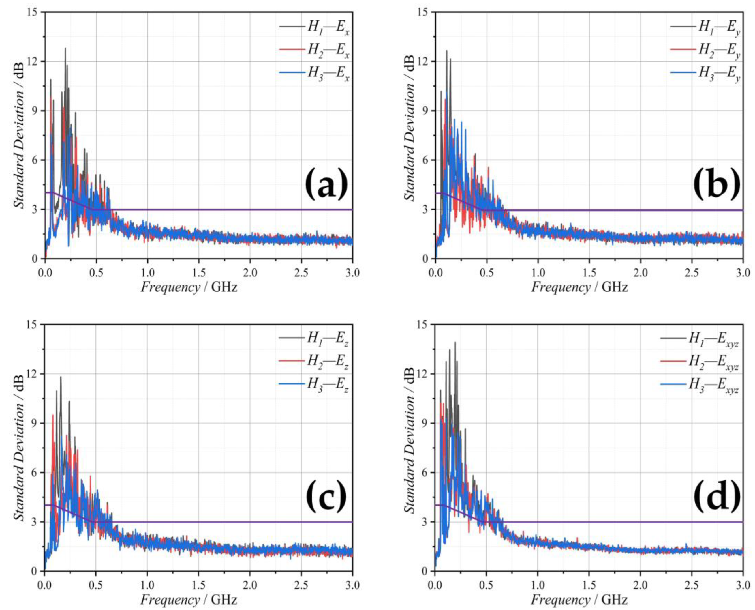
Our experiments, reflected in
Figure 7,
Figure 8 and
Figure 9, demonstrate that varying the number of samples (
N1 = 60,
N2 = 90,
N3 = 360) of the metasurface stirrer significantly impacts field uniformity across different heights within the chamber. Notably, the LUF was reduced to around 700 MHz, indicating that the MRC can maintain uniform fields at lower frequencies than traditional RCs. This reduction in LUF, coupled with the expanded test volume, positions the MRC as a more versatile and efficient tool for electromagnetic testing, especially for larger or more complex test subjects.
In our experiment, we focused on the impact of different stirrers on the performance of the reverberation chamber (RC). While all stirrers were loaded into the RC, only one was operated at a time to isolate their individual effects (
Figure 10). This approach allowed us to directly compare the influence of each stirrer design on the electromagnetic field distribution within the RC.
To assess the performance of these stirrers, we specifically chose to plot S-parameters at three distinct frequencies: 707 MHz, 1 GHz, and 3 GHz. The selection of these frequencies was strategic and informed by their relevance to our analysis. The frequency of 707 MHz represents the lowest usable frequency (LUF) of the RC, serving as a critical benchmark for evaluating baseline performance of the chamber. The 1 GHz frequency falls within the operational band of the metasurface, providing insights into the optimized performance of the metasurfaced chamber (MRC). Lastly, the 3 GHz frequency marks the upper limit of the operational range for the chamber, offering a comprehensive view of performance across its entire spectrum. This careful selection of frequencies ensures a robust and comprehensive evaluation of capabilities and effectiveness of the MRC under various operational scenarios.
Figure 11 illustrates the relationship between the S-parameter of the receiving antenna and the rotation angle of the metasurface stirrer at these different frequencies. The results demonstrate how rotation of the stirrer impacts electromagnetic field distribution in the chamber.
Further insights into the effectiveness of the stirrer designs are provided by the normalized angle autocorrelations
R(
θ), as shown in
Figure 12. These correlations reveal that the metasurface stirrer yields smaller correlations compared to the horizontal stirrer, indicating a more uniform field distribution. However, it is the vertical stirrer, with its irregular blades and larger stirring surface, that shows superior performance. This finding underscores the significance of stirrer design in influencing the electromagnetic field distribution within the RC, highlighting the importance of considering both the physical and operational characteristics of stirrers in the design of efficient RCs.
The K factor results, presented in
Figure 13, reveal that the metasurface stirrer performs better than the horizontal stirrer but is less effective than the vertical stirrer. This suggests that while the metasurface stirrer contributes to a more complex multipath environment, its design could be further optimized. The TSCS data, shown in
Figure 14, corroborate this, placing the metasurface stirrer at a mid−level performance in terms of scattering efficiency. This implies that while the metasurface stirrer introduces improvements in certain aspects, there is potential for further enhancement, particularly in creating a more complex and richer multipath environment within the chamber.
In our study, the analysis of the enhanced back scattering coefficient (eb) of the metasurface stirrer, as depicted in
Figure 15, provides insightful observations. The data from 1 GHz to 3 GHz reveal that the eb value consistently hovers around 2, a strong indicator of effective stirring capability in the MRC. This near-constant eb value across a broad frequency range underscores the proficiency of the metasurface stirrer in maintaining a well-stirred environment within the chamber.
Such a well-stirred characteristic is essential for ensuring the accuracy and reliability of measurements conducted in the MRC. The consistency of the eb value, especially in the higher frequency range, illustrates the ability of the metasurface stirrer to distribute electromagnetic waves uniformly, thus reducing the potential for measurement anomalies or biases. This finding is particularly relevant for applications requiring precise and reliable antenna performance evaluations, where the uniformity of the electromagnetic field within the testing environment is paramount.
5. Conclusions
This study has successfully demonstrated the implementation and efficacy of a planar rotatable 1-bit random coding metasurface in creating a metasurfaced reverberation chamber (MRC). The designed and fabricated metasurface has been rigorously evaluated for its stirring efficiency using various parameters, including the quality factor (Q factor), number of samples, standard deviation, angle autocorrelation, average K factor, total scattering cross section (TSCS), and the enhanced back scattering coefficient (eb).
Our findings reveal that the metasurface stirrer effectively reduces the lower usable frequency (LUF) while simultaneously expanding the maximum test volume. However, it is important to note that at higher frequencies, the Q factor experiences a decrease due to the medium loss of the metasurface. This aspect highlights a potential area for optimization in future designs. Additionally, the stirring volume of the metasurface stirrer, calculated as π × (255 mm × 255 mm × 10 mm), is considerably smaller compared to the volumes achieved by traditional metallic stirrers. This difference in stirring volume is a critical factor in the overall performance of the MRC.
Comparative analysis with traditional stirrers indicates that the metasurface stirrer outperforms the horizontal stirrer in terms of stirring efficiency but falls short of the efficiency achieved by the vertical stirrer. This gap in performance could potentially be addressed by increasing the size of the metasurface in future designs. Despite these variations, the enhanced back scattering coefficient results unequivocally demonstrate that the MRC maintains a well-stirred environment, a crucial factor for its application in electromagnetic compatibility testing and antenna measurements.
In summary, the research presented in this paper not only underscores the potential of the metasurfaced reverberation chamber in enhancing electromagnetic field testing but also lays the groundwork for future advancements in this domain. The metasurface stirrer, with its unique design and operational characteristics, offers a promising alternative to traditional stirrers, balancing performance and efficiency.
6. Patents
There is a Chinese patent resulting from the work reported in this manuscript.
CN108318758A (2018-01-23): A Metasurfaced Reverberation Chamber.
Author Contributions
Conceptualization, H.S., Z.L. and C.G.; methodology, H.S.; software, H.S.; validation, A.C., H.S. and C.S.; formal analysis, X.L.; investigation, H.S., Y.Z. and Z.X.; resources, H.S.; data curation, Q.X. and C.S.; writing—original draft preparation, H.S.; writing—review and editing, X.L.; visualization, A.C. and C.S.; supervision, Q.X., Z.L. and C.G.; project administration, H.S. All authors have read and agreed to the published version of the manuscript.
Funding
This research was funded by the Fund of Qing Lan Project of Jiangsu Province, grant number [1004-YQR22031], and the Fund of Prospective Layout of Scientific Research for NUAA (Nanjing University of Aeronautics and Astronautics), grant numbers [1004-ILA22002] and [1004-ILA22068].
Data Availability Statement
Data are contained within the article.
Acknowledgments
We are grateful to NUAA for the Reverberation Chamber to test the data.
Conflicts of Interest
The authors declare no conflict of interest.
References
- Sun, H.; Li, Z.; Gu, C.; Xu, Q.; Chen, X.; Sun, Y.; Lu, S.; Martin, F. Metasurfaced reverberation chamber. Sci. Rep. 2018, 8, 1–10. [Google Scholar] [CrossRef] [PubMed]
- Hajiahmadi, M.J.; Faraji-Dana, R.; Caloz, C. Metasurface-Based Time-Reversal Focusing for Brain Tumor Microwave Hyperthermia. IEEE Trans. Antennas Propag. 2022, 70, 12237–12246. [Google Scholar] [CrossRef]
- Harrington, R.F. Time-Harmonic Electromagnetic Fields; McGraw-Hill Book Co.: New York, NY, USA, 1961; pp. 232–235. [Google Scholar]
- Balanis, C.A. Advanced Engineering Electromagnetics; John Wiley & Sons: Hoboken, NJ, USA, 2012. [Google Scholar]
- Hill, D.A. Electromagnetic Fields in Cavities: Deterministic and Statistical Theories; IEEE Press: New York, NY, USA, 2009. [Google Scholar]
- Gros, J.B.; Lerosey, G.; Mortessagne, F.; Kuhl, U.; Legrand, O. Uncorrelated configurations and field uniformity in reverberation chambers stirred by reconfigurable metasurfaces. Appl. Phys. Lett. 2021, 118, 144101. [Google Scholar] [CrossRef]
- Holloway, C.L.; Hill, D.A.; Ladbury, J.M.; Koepke, G. Requirements for an effective reverberation chamber: Unloaded or loaded. IEEE Trans. Electromagn. Compat. 2006, 48, 187–194. [Google Scholar] [CrossRef]
- Hubrechsen, A.; Remley, K.A.; Catteau, S. Reverberation chamber metrology for wireless internet of things devices: Flexibility in form factor, rigor in test. IEEE Microw. Mag. 2022, 23, 75–85. [Google Scholar] [CrossRef]
- Mahfouz, M.Z.; Vogt-Ardatjew, R.A.; Kokkeler, B.; Glazunov, A.A. Measurement and Estimation Methodology for EMC and OTA Testing in the VIRC. IEEE Trans. Electromagn. Compat. 2022, 65, 3–16. [Google Scholar] [CrossRef]
- Gifuni, A.; Bastianelli, L.; Gradoni, G.; Moglie, F.; Perna, S.; Smartt, C.; Primiani, V.M. On the shielding effectiveness calculation of enclosures through measurements in reverberation chambers. IEEE Trans. Electromagn. Compat. 2021, 63, 1395–1406. [Google Scholar] [CrossRef]
- Xue, W.; Chen, X.; Yang, Y.; Huang, Y. Average Rician K-factor-based uncertainty model of measured antenna efficiency using the reference antenna method in reverberation chambers. IEEE Trans. Instrum. Meas. 2021, 71, 1–11. [Google Scholar] [CrossRef]
- Reis, A.; Sarrazin, F.; Richalot, E.; Meric, S.; Sol, J.; Pouliguen, P.; Besnier, P. Radar cross section pattern measurements in a mode-stirred reverberation chamber: Theory and experiments. IEEE Trans. Antennas Propag. 2021, 69, 5942–5952. [Google Scholar] [CrossRef]
- Reis, A.; Sarrazin, F.; Besnier, P.; Pouliguen, P.; Richalot, E. Contactless antenna gain pattern estimation from backscattering coefficient measurement performed within a reverberation chamber. IEEE Trans. Antennas Propag. 2021, 70, 2318–2321. [Google Scholar] [CrossRef]
- Holloway, C.L.; Shah, H.A.; Pirkl, R.J.; Young, W.F.; Hill, D.A.; Ladbury, J. Reverberation chamber techniques for determining the radiation and total efficiency of antennas. IEEE Trans. Antennas Propag. 2012, 60, 1758–1770. [Google Scholar] [CrossRef]
- Holloway, C.L.; Smith, R.S.; Dunlap, C.R.; Pirkl, R.J.; Ladbury, J.; Young, W.F.; Hill, D.A.; Hansell, W.R.; Shadish, M.A. Validation of a two-antenna reverberation chamber technique for estimating the total and radiation efficiency of antennas. In Proceedings of the International Symposium on Electromagnetic Compatibility (EMC EUROPE), Rome, Italy, 17–21 September 2012; pp. 1–6. [Google Scholar]
- Holloway, C.L.; Smith, R.S.; Dunlap, C.R.; Pirkl, R.J.; Ladbury, J.; Young, W.F.; Hansell, W.R.; Shadish, M.A.; Sullivan, K. Validation of a one-antenna reverberation-chamber technique for estimating the total and radiation efficiency of an antenna. In Proceedings of the IEEE International Symposium on Electromagnetic Compatibility (EMC), Pittsburgh, PA, USA, 6–10 August 2012; pp. 205–209. [Google Scholar]
- Xu, Q.; Huang, Y. Anechoic and Reverberation Chambers: Theory Design and Measurements; Wiley: Hoboken, NJ, USA, 2018. [Google Scholar]
- IEC 61000-4-21:2001; Electromagnetic Compatibility (EMC)—Part 4-21: Testing and Measurement Techniques—Reverberation Chamber Test Methods. IEC Standard: Geneva, Switzerland, 2011.
Figure 1.
Unit cell geometric structure: (a) top view of “0” element; (b) perspective view of “1” element.
Figure 1.
Unit cell geometric structure: (a) top view of “0” element; (b) perspective view of “1” element.
Figure 2.
The 1−bit random coding metasurface schematic: (a) coding sequence from optimization algorithm; (b) simulation model overview.
Figure 2.
The 1−bit random coding metasurface schematic: (a) coding sequence from optimization algorithm; (b) simulation model overview.
Figure 3.
Fabricated 1-bit random coding metasurface: photographic representation.
Figure 3.
Fabricated 1-bit random coding metasurface: photographic representation.
Figure 4.
Measurement setup overview: (a) system schematic; (b) MRC photograph with 1.2 m × 1.2 m × 0.8 m dimensions; (c) control device in the measurement system; (d) transmitting and receiving antennas.
Figure 4.
Measurement setup overview: (a) system schematic; (b) MRC photograph with 1.2 m × 1.2 m × 0.8 m dimensions; (c) control device in the measurement system; (d) transmitting and receiving antennas.
Figure 5.
Receiving antenna sampling points: schematic layout.
Figure 5.
Receiving antenna sampling points: schematic layout.
Figure 6.
Q factor measurement results: (a) traditional RC; (b) MRC with metasurface stirrer.
Figure 6.
Q factor measurement results: (a) traditional RC; (b) MRC with metasurface stirrer.
Figure 7.
Standard deviation in MRC with N1 = 60 samples: (a) the electric field component in the x-direction; (b) the electric field component in the y-direction; (c) the electric field component in the z-direction; and (d) the total electric field in three directions of xyz.
Figure 7.
Standard deviation in MRC with N1 = 60 samples: (a) the electric field component in the x-direction; (b) the electric field component in the y-direction; (c) the electric field component in the z-direction; and (d) the total electric field in three directions of xyz.
Figure 8.
Standard deviation in MRC with N2 = 90 samples: (a) the electric field component in the x-direction; (b) the electric field component in the y-direction; (c) the electric field component in the z-direction; and (d) the total electric field in three directions of xyz.
Figure 8.
Standard deviation in MRC with N2 = 90 samples: (a) the electric field component in the x-direction; (b) the electric field component in the y-direction; (c) the electric field component in the z-direction; and (d) the total electric field in three directions of xyz.
Figure 9.
Standard deviation in MRC with N3 = 360 samples: (a) the electric field component in the x-direction; (b) the electric field component in the y-direction; (c) the electric field component in the z-direction; and (d) the total electric field in three directions of xyz.
Figure 9.
Standard deviation in MRC with N3 = 360 samples: (a) the electric field component in the x-direction; (b) the electric field component in the y-direction; (c) the electric field component in the z-direction; and (d) the total electric field in three directions of xyz.
Figure 10.
Angle autocorrelation experiment: (a) experimental setup sketch; (b) system photograph.
Figure 10.
Angle autocorrelation experiment: (a) experimental setup sketch; (b) system photograph.
Figure 11.
Frequency−dependent S−parameters of metasurface stirrer.
Figure 11.
Frequency−dependent S−parameters of metasurface stirrer.
Figure 12.
Normalized angle autocorrelation comparison: three stirrers at (a) 707 MHz, (b) 1 GHz, (c) 3 GHz.
Figure 12.
Normalized angle autocorrelation comparison: three stirrers at (a) 707 MHz, (b) 1 GHz, (c) 3 GHz.
Figure 13.
K factor comparison among three stirrers.
Figure 13.
K factor comparison among three stirrers.
Figure 14.
Measured (a) chamber decay time and (b) TSCS: comparison among three stirrers.
Figure 14.
Measured (a) chamber decay time and (b) TSCS: comparison among three stirrers.
Figure 15.
Enhanced back scattering coefficient (eb) in the MRC.
Figure 15.
Enhanced back scattering coefficient (eb) in the MRC.
| Disclaimer/Publisher’s Note: The statements, opinions and data contained in all publications are solely those of the individual author(s) and contributor(s) and not of MDPI and/or the editor(s). MDPI and/or the editor(s) disclaim responsibility for any injury to people or property resulting from any ideas, methods, instructions or products referred to in the content. |
© 2023 by the authors. Licensee MDPI, Basel, Switzerland. This article is an open access article distributed under the terms and conditions of the Creative Commons Attribution (CC BY) license (https://creativecommons.org/licenses/by/4.0/).


 ,
, 