Article

A Fuzzy-Based Proportional–Integral–Derivative with Space-Vector Control and Direct Thrust Control for a Linear Induction Motor

by
Mohamed I. Abdelwanis
1,*,
Fayez F. M. El-Sousy
2 and
Mosaad M. Ali
1
1
Electrical Engineering Department, Faculty of Engineering, Kafrelsheikh University, Kafr El Sheikh 6860404, Egypt
2
Department of Electrical Engineering, College of Engineering, Prince Sattam bin Abdulaziz University, Al Kharj 16273, Saudi Arabia
*
Author to whom correspondence should be addressed.
Electronics 2023, 12(24), 4955; https://doi.org/10.3390/electronics12244955
Submission received: 22 October 2023 / Revised: 26 November 2023 / Accepted: 4 December 2023 / Published: 10 December 2023

Abstract

:
In this study, the analysis and control of a multi-phase linear induction motor loaded with a variable mechanical system are carried out. Mathematical models are established, and simulation results are analyzed for an improved proportional–integral–derivative controller with closed-loop vector control for PLIM. To make the PID controller more responsive to load thrust disturbances, a fuzzy PID load thrust observer was developed. The FPID is similarly based on space-vector modulation DTC technology to regulate the PLIM’s speed, flux, and thrust. The FPID output is used to calculate the reference thrust force, which is compared to the actual thrust value to calculate the second error. To maintain the linear speed of the PLIM at the specified reference values and at different load values, the FPID controller settings are adjusted. Four indicators were used to compare the capabilities of the FPID controller with those of the conventional PID controller in order to evaluate the performance of PLIM in both cases. These indices represent the individual SSE for each operational phase and the total SSE for the entire loading period. According to the simulation results, the FPID works better than a regular PID when used to adjust the operation of DTC-SVM to drive a PLIM to improve the overall system performance. The simulation results using MATLAB Simulink for a PLIM-drive system show that the proposed FPID control provides improved control behavior and operating performance with fast and accurate speed tracking.

1. Introduction

1.1. Motivation

Recently, PLIMs have drawn a lot of interest from academia and industry [1] because of their benefits: direct drive, greater acceleration and deceleration, less volume, and other characteristics [2]. The PLIMs’ most evident advantages are their high beginning thrust, no gear system being required, no rotational losses, reduced mechanical losses, silence, and low cost [3]. The use of PLIMs has several disadvantages, such as a bigger air gap, the problem of an end effect, and a large value of flux leakage [4]. The aim of this study is to enhance the operation of a poly-phase linear induction motor. The design and performance study of classic PID and optimal FPID in relation to the PLIM that drives variable mechanical systems is presented in this study [5]. To demonstrate how superior the suggested control strategy is over the conventional PID controller approach, a comparison between the FPID method and the regular PID method is given. The suggested control system offers improved transient control performance with fast and precise speed tracking, according to extensive simulation findings.

1.2. Literature Review

PLIMs have similar driving principles to poly-phase induction motors [6]. But, the control properties of PLIMS are more complicated according to the phenomenon of the end effect [7]. Direct thrust control was developed to achieve a quick reaction during operation and to decouple the dynamic force and flux linkage of the primary part [8]. When compared to field-oriented control [9], the DTC technique has greater characteristics, like less reliance on machine parameters, better efficiency, and not needing coordinate transformation [10]. The optimal inverter voltage vector for controlling primary flux and thrust force is determined by the DTC strategy control mechanism through the employment of hysteresis controllers and a switching table. The DTC approach has various limitations as a result of this control mechanism, like larger ripples of primary flux and thrust, and needs variation in switching frequency. As shown in [11], several adjustments are made to reduce thrust ripples and flux while maintaining a fixed switching frequency.
In terms of speed control, PID controllers are commonly used in all studies [12]. The typical PI controller, on the other hand, cannot meet the demand for multi-variable nonlinear control in high-performance PLIM systems [13]. Furthermore, the traditional PID controller has inadequate adaptability when it comes to load changes. In this work, space vector modulation was used in place of the switching table to pick a voltage vector and to achieve a fixed switching frequency.
Because of its ease, robustness of implementation, and flexibility to load and speed changes, FPID controllers are gradually being implemented in electrical motor speed control [14,15]. This research proposes a load thrust mechanism based on DTC-SVM [16] for the PLIM using an FPID speed controller. The desired control technique achieves robust control characteristics. Under the influence of load thrust, the desired control method was used to enhance speed-tracking. To illustrate that the proposed control strategy is feasible, simulation results are shown. Improvements are made to the equivalent circuit model of a linear induction motor with one side in [17].
The improved time and speed response of a poly-phase IM by using a fuzzy controller based on a multi-level inverter is presented in [18]. The optimal parameters of an FPID controller were investigated in the Dual Axis Turntable Servo System [19], nonlinear systems [20], and integrated power systems [21]. Reference [22] presents an experimental investigation of a turntable servo system controlled by FPID. The predictive functional control structure was used to enhance PID parameters using fuzzy logic [23]. Reference [24] shows how to simulate and control the performance of an evaporator using traditional PID and optimized FPID.
Reference [25] shows how to tune a PID controller for voltage and frequency control of an IM using a hybrid fuzzy–genetic method. In various applications, including the control of three-phase induction machines [26], the design of brushless DC motors [27], the deregulated LFC of multi-area power systems [28], and the three-link robotic manipulator system [29], fuzzy controllers are employed to determine PID parameters. Reference [30] offers fuzzy logic-based methods for maintaining the maximum torque value for a poly-phase rotary induction motor (PRIM). The DTC of PLIM is presented in [31]. Reference [32] shows the fuzzy-based sensorless speed used to control induction motors. The control of the PRIM using a hybrid fuzzy logic with a neural network is explored in [33]. The BSO algorithm for a three layer neural network was used as a practical application in UAV edge control [34]. In reference [35], vector control theory was used to achieve a high operating performance for PRIM. In Reference [36], nonlinear fractional PID and a fuzzy logic [37] controller were used for the speed control of conventional rotary machines. PLIM servo drives hybrid control using neural networks and fuzzy logic [38].
The following are the main contributions of the proposed system:
  • The study and modeling of classic PID and optimal FPID controllers in relation to the PLIM that drives variable systems is presented in this study.
  • To accomplish the working conditions, an FPID controller is suggested to maintain the speed of PRIM at the present settings.
  • The simulation results of a direct trust control approach to PLIM control are explained.
  • To compare the functioning of an FPID controller with a typical PID controller, operational indicators are offered, including steady state error (SSE), oscillation index (OI), overall steady state value (OSSV), and rise time index (RTI).
  • These indices are used to calculate the controller rise time and motor linear speed.

1.3. Paper Organization

This work is organized as follows: the first part presents the introduction. The second part provides the full dynamic model of PLIM. The third part describes the space-vector modulation for direct thrust control of PLIM. The fourth part describes the proposed procedure for the fuzzy PID controller of PLIM. Finally, the fifth part presents the discussion and conclusion of this work.

2. PLIM Dynamic Model with End Effects

Without addressing the influence of the end effect, the PLIM circuit is comparable to the rotating IM circuit [39]. Based on the analogous circuit proposed in [40], the PLIM mathematical model is derived from a synchronous reference frame. The dynamic model of PLIM is described using Equations (1)–(10).
The voltage equations for the dq-axis can be determined from Equations (1) and (2) [16].
u d a = R a i d a + p ψ d a - ( ω 1 ) ψ q a u d b = R b i d b + p ψ d b + ( ω 1 - ω 2 ) ψ q b = 0
u q a = R a i q a + p ψ q a - ( ω 1 ) ψ d a u q b = R b i q b + p ψ q b + ( ω 1 - ω 2 ) ψ d b = 0
where ω1 and ω2 are the primary and secondary angular speed, respectively; p is the derivative d/dt; Ra and Rb are the primary and secondary resistances, respectively; and both primary and secondary symbols are denoted by the subscripts a and b.
The flux linkage of the PLIM dq-axis can be computed using Equations (3) and (4) [16].
ψ da = L a i da + L m e q i da ψ db = L b i db + L m e q i db
ψ q a = L a i q a + L m e q i q a ψ qb = L b i qb + L m e q i qb
The electrical thrust of PLIM can be calculated using Equations (1)–(4), as follows:
F e = 3 π 2 τ ψ d a i q a ψ q a i d a
The mechanical balance of the PLIM equation can be written as follows:
F e = F L + m d v r d t + B v r
where B is the damping coefficient, τ is the pole pitch of the primary winding, m is the mass, FL is the load force, and vr is the linear speed of PLIM. Based on f(Q), the impact of end effects on PLIM parameters is as follows [40]:
f ( Q ) = ( 1 exp ( Q ) ) Q
where the factor Q is
Q = L a R a v r ( L l b + L m )
The modified magnetizing inductance Lmeq is computed as follows:
L m e q = ( 1 f ( Q ) ) L m
where Lb is the secondary inductance, La is the primary inductance, and Lm is the magnetizing inductance between primary and secondary [39]. The updated primary and secondary inductances can then be computed using Equation (10).
L a = L l a + L m e q L b = L l b + L m e q
where Lla is the primary leakage inductance and Llb is the secondary leakage inductance.

3. Direct Thrust Control of PLIM by Space-Vector Modulation

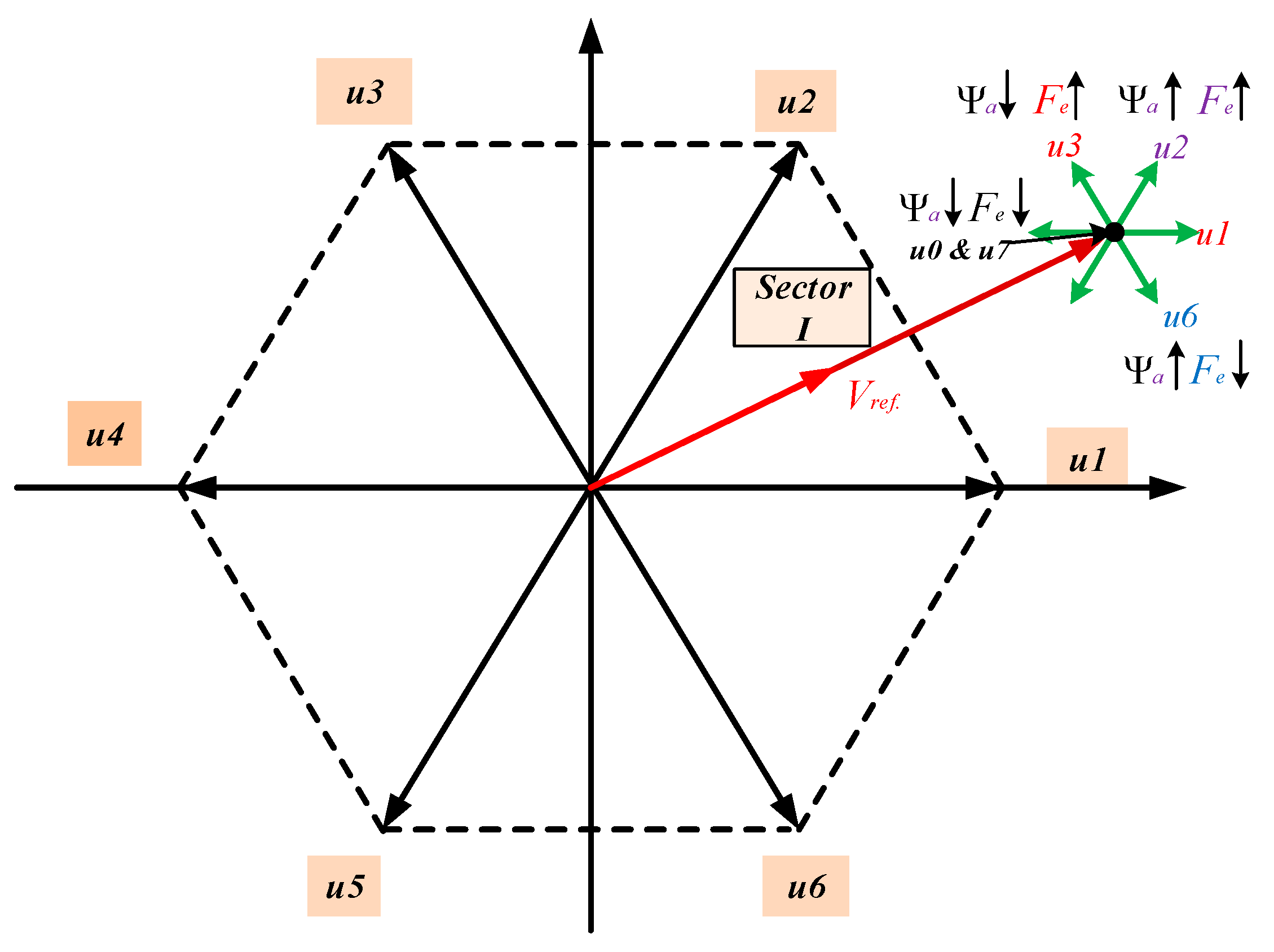
This work presents SVM-DTC with closed-loop control using fuzzy logic PID control. In order to activate the control switch of the inverter, the sets of controlled device cases for each controlled device produce eight voltage vectors. Figure 1 depicts the six voltage vectors that are active (u1–u6); u0 and u7 are zero [41]. The vector form of the reference primary voltage is calculated from the following:
u 1 = d ψ a d t + R a I a
The resistance of the primary, Ra, can be ignored.
Related to the aforementioned premise, controlling the output reference voltage can control the path of flux linkage for the primary part. By selecting the appropriate vector, the primary flux’s route progresses in the voltage direction of the inverter output.
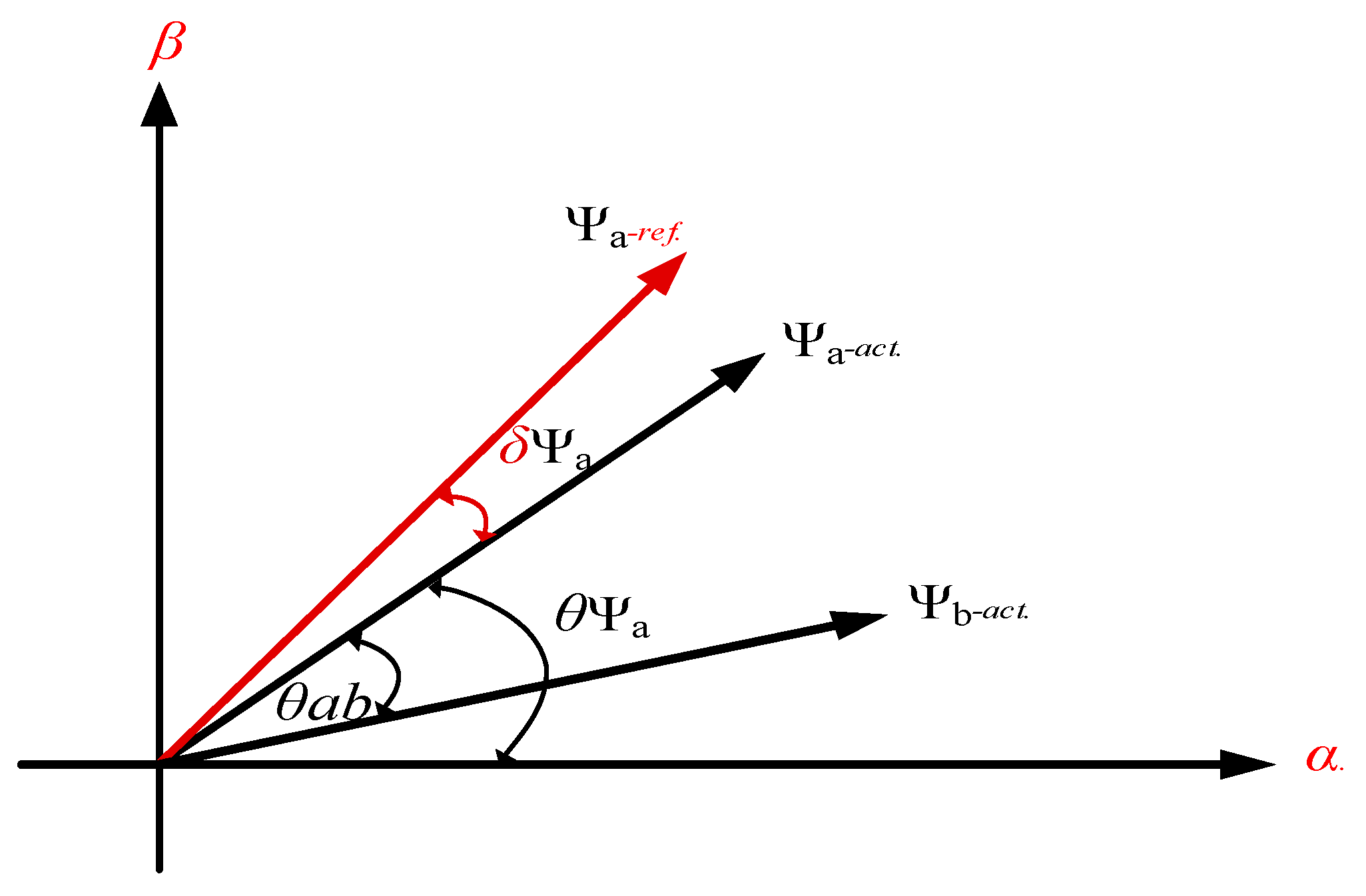
The PLIM thrust, as shown in Equation (5), can also be stated in other forms based on the flux linkage components. The primary and secondary flux vectors, the angle between the secondary, and primary flux in αβ-plain are shown in Figure 2.
F e = 3 π 2 τ L m e q σ L a L b ψ a ψ b sin θ a b
where σ can be calculated as
σ = 1 L m e q 2 L a L b
It should be remembered that increasing or decreasing the value of the thrust rate is accomplished by choosing the switching vector of the voltage that controls the value of the flux angle (θab).
The flux of the primary part and force may be changed at the same time by choosing an appropriate inverter voltage vector and applying the SVM approach. Figure 3 depicts the selection of the best vector of the inverter voltage to realize the requisite thrust and flux.
The main flux connection is positioned in the d-plain according to the field-oriented control principle [41]. Modifications to the motor input voltage can be written as follows:
u d a = R a i d a + p ψ d a u q a = R a i q a + ( ω a ) ψ d a
By substituting Equation (14) into Equation (5), the developed payment equation can be calculated as follows:
F e = 3 π 2 τ R a ψ a u q a ω s ψ a
According to the equations above, the d-axis primary voltage, uda, can be utilized to change the magnitude of the primary flux, while the q-axis motor input voltage, uqa, affects the developed thrust.

4. The Suggested Design Process for the PLIM Fuzzy Controller

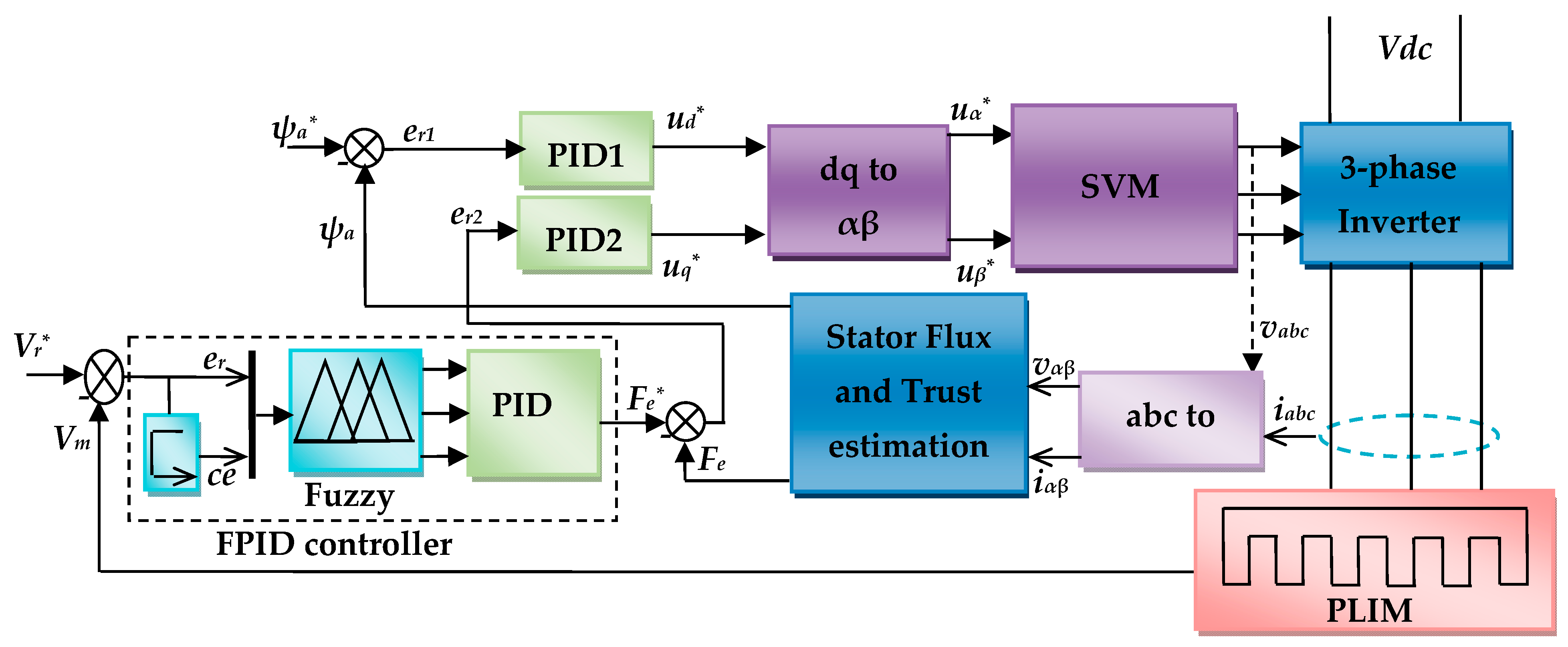
The suggested closed-loop speed controller based on a fuzzy PID control approach for the PLIM is shown schematically in Figure 4. Actually, the SVM module receives the coordinates for the reference voltage vector in (α, β) from the basic DTC selection table module and uses those coordinates to create the signals that drive the inverter’s switches. The DTC-SVM control method in PLIM is characterized by its simplicity and high motor speed accuracy [10]. As a result, as illustrated in Figure 4, the suggested controller uses the vector control approach. The major goal is to keep the electromagnetic thrust and flux under control.

4.1. Fuzzy-Based Control Strategy with Vector Control

To enhance the system’s performance, a closed-loop DTC-SVM was included. The error speed (er(t)) is the variation between the measured and reference linear speeds (Vm and Vr, respectively). It is possible to calculate the error signal’s magnitude and sign using (16). In order to compensate for this inaccuracy, the FPID controller adjusts the motor reference trust (Fe*) deviation as follows [42]:
e r ( t ) = V r V m
F e * ( t ) = K p e r ( t ) + K i e r ( t ) d t + ( K d ) d c e ( t ) d t
The reference direct voltage Ud* can be calculated from the following:
e r 1 ( t ) = ψ a * ψ a
U d * = K p 1 e r 1 ( t ) + K i 1 e r 1 ( t ) d t + K d 1 d c e 1 ( t ) d t
The reference quadrature voltage Uq* can be calculated from the following:
e r 2 ( t ) = F e * F e
U q * = K p 2 e r 2 ( t ) + K i 2 e r 2 ( t ) d t + K d 2 d c e 2 ( t ) d t
A PID controller must be tuned to calculate the six factors, Ki1, Kd1, Kp1, Ki2, Kd2, and Kp2, that are used to calculate the voltages Ud* and Uq*.
The firing angle of controlled switches is calculated using the values of the α-axis and β-axis voltage components uα and uβ, respectively, given from Equations (22) and (23):
u α = U d * cos θ ψ * U q * sin θ ψ *
u β = U d * sin θ ψ * + U q * cos θ ψ *

4.2. Design of Closed-Loop Control Systems

A closed-loop vector control was studied to enhance the PLIM performance. As the error signal, the difference between the actual and reference linear speeds is used.
The FPID controller creates the corrected motor stator frequency deviation based on the speed error to properly compensate for the increased mistake. A FPID controller must be programmed to calculate the three factors, Ki, Kd, and Kp, that reduce the cost function Fe* (t) [43].
F e * = K p e r ( t ) + K p T i e r ( t ) d t + ( K p T d ) d c e ( t ) d t
The derivative and integral time constants are Td and Ti, respectively.
The PID is regarded as the primary controller in the suggested FPID controller, while the fuzzy system is considered the secondary controller that regulates the PID factors. Two signals, the speed error and variation of this error, are used as input variables (er(t) and ce(t)) to the fuzzy system, while the tuned PID factors (Ki, Kp, and Kd) are used as output variables. The basic procedure of FPID is shown in Figure 5 [44]. The inverter input signal is controlled using the tuned PID settings. As in Equations (25) and (26), the Kp’ and Kd’ lie between values of 0 and 1, as in [45]:
K p = K p K p min K p max K p min
K d = K d K d min K d max K d min
We can also calculate the integral time constant from the following relationship using the coefficient βi:
T i = β i . T d
The FPID factors Ki, Kd, and Kp that have been fine-tuned are updated as follows:
K p = ( K p max K p min ) K p + K p min
K d = ( K d max K d min ) K d + K d min
The integral factor Ki is calculated using the following formula:
K i = K p β i . T d = K p 2 β i . K d
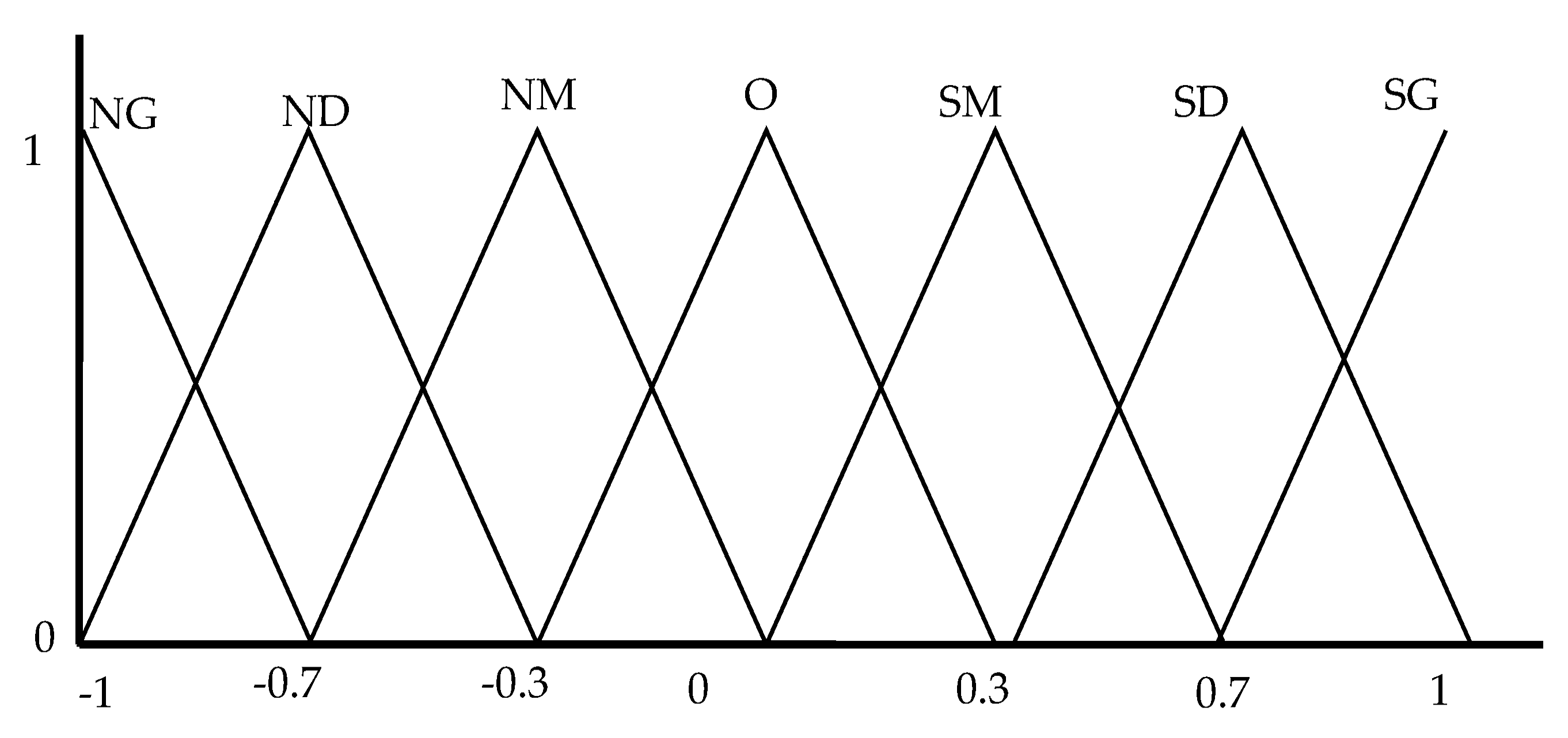
Figure 6 depicts the fuzzy-based technique for fine-tuning different PID coefficients in order to obtain a stable control signal. As shown in Figure 6, the input variables are represented in the fuzzed using seven overlapping triangular fuzzy memberships [46]. As seen in Figure 7 and Figure 8, the fuzzification method is also used for output variables.
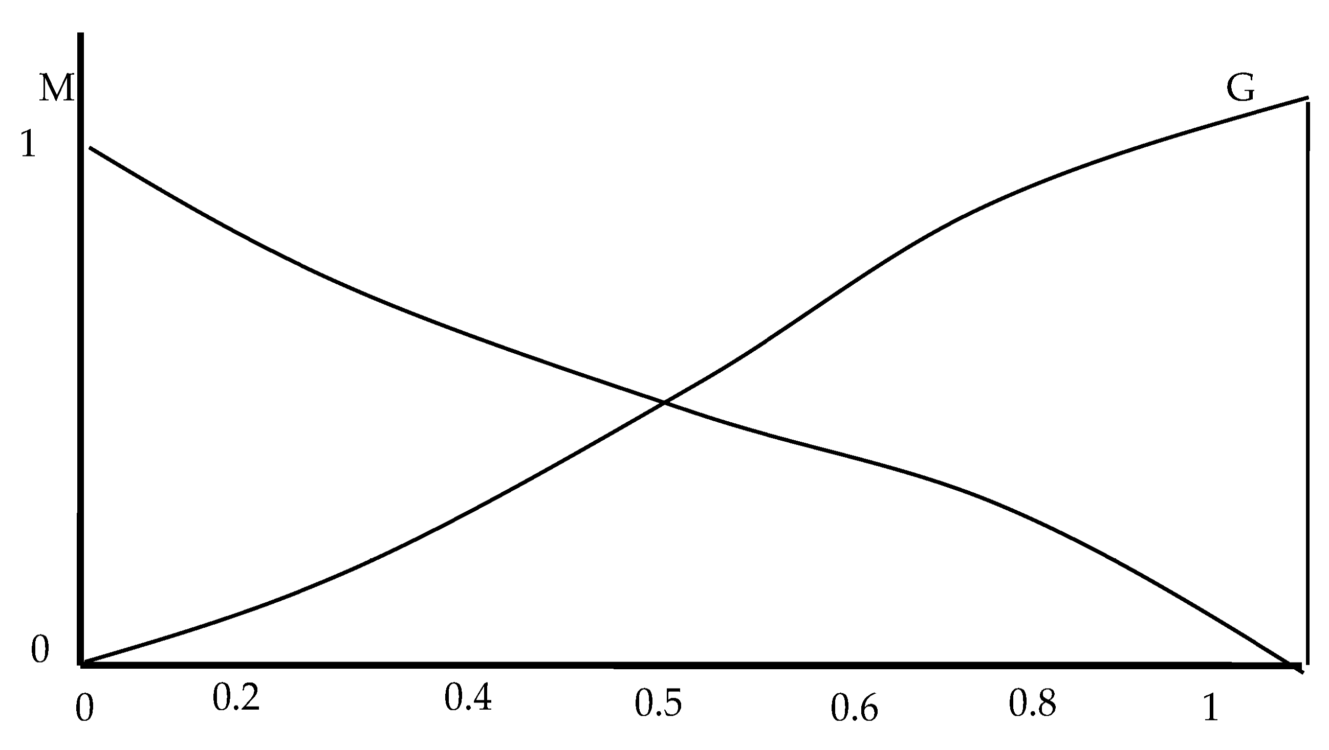
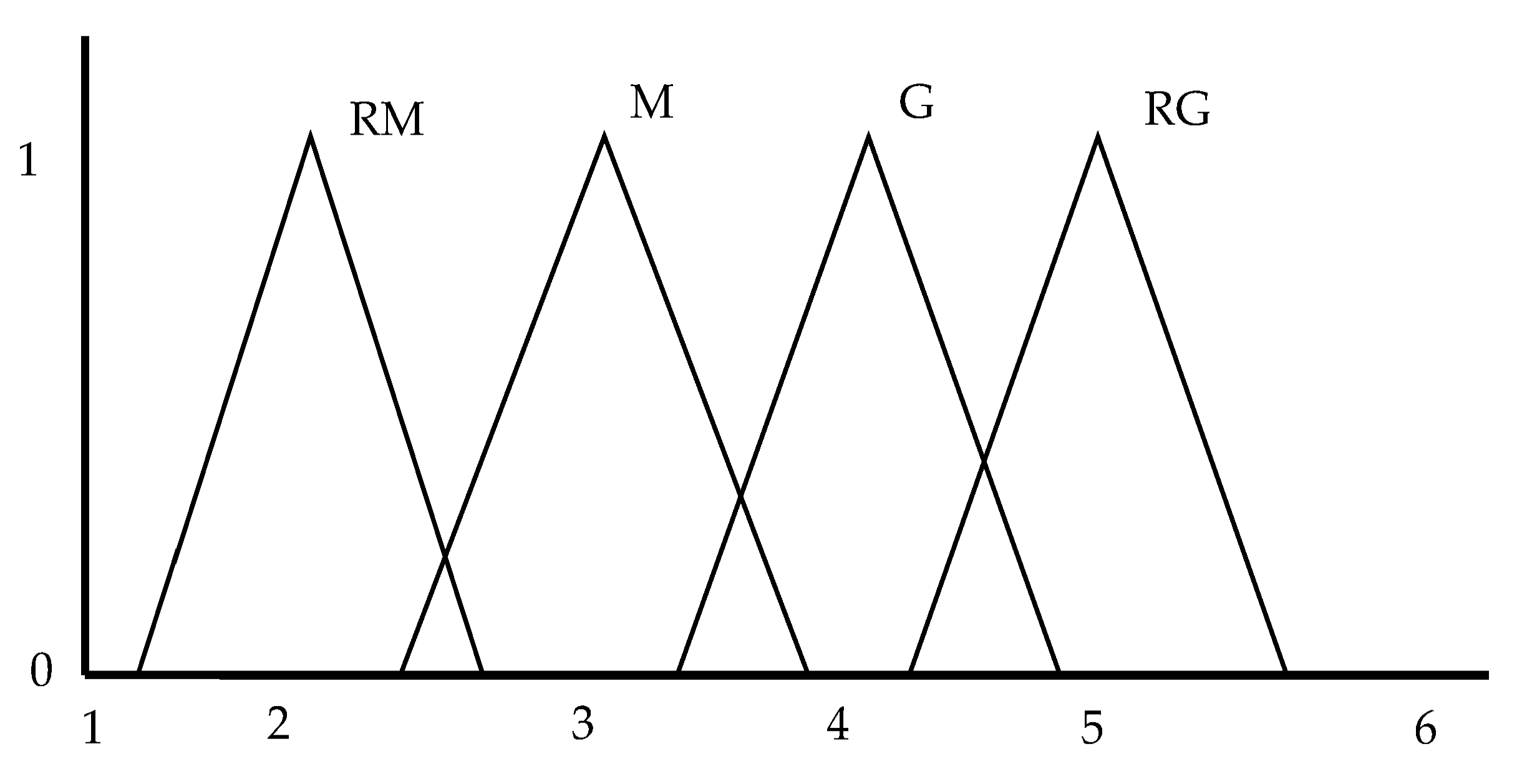
As illustrated in Figure 8, the operating range of all outputs (Kp, Kd) is selected. Each discursive universe is divided into two fuzzy sets that overlap. The fuzzy simulation of the coefficient βi is depicted in Figure 9 using four fuzzy sets. A degree of membership (M in the range (0,1)) is assigned to every variable in the fuzzy input or output. The fuzzy deduction system is created for the input and output variables with the aid of the fuzzy rules listed in Table 1.

5. Applications

5.1. Simulated Cases

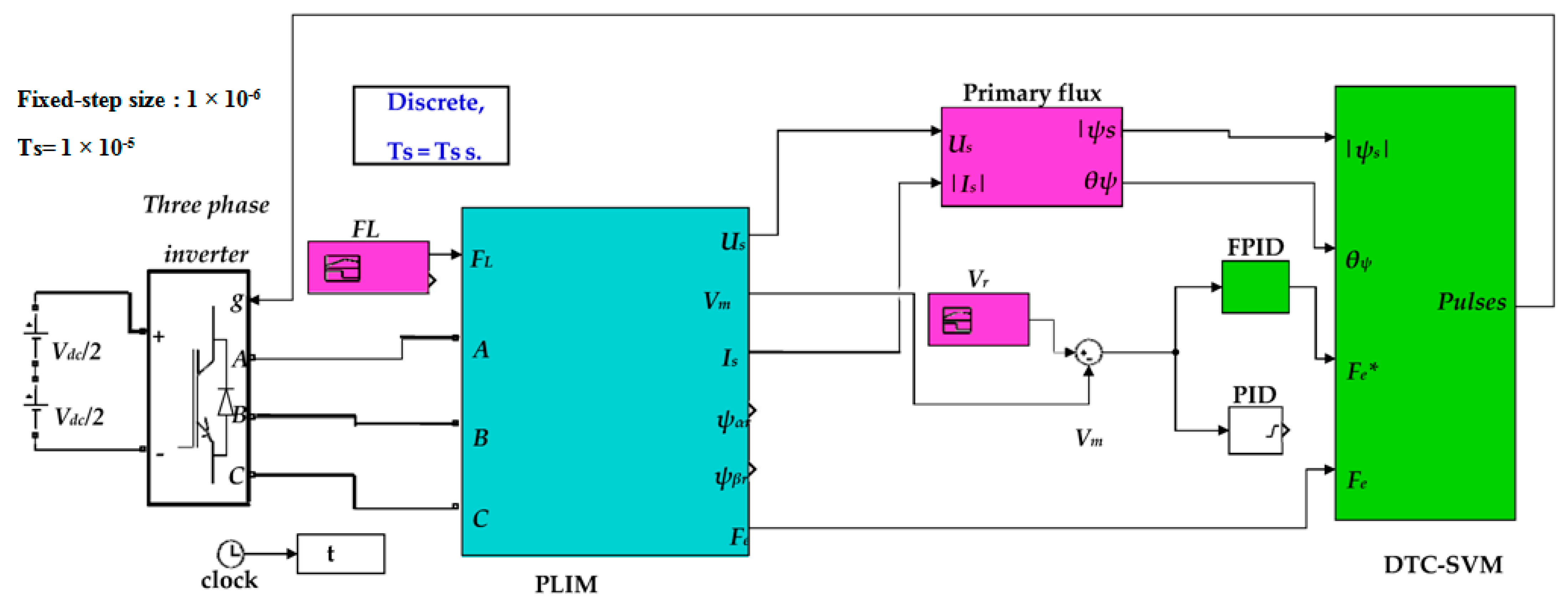
The MATLAB/Simulink package implements the model of the PLIM-driven variable loading system fed from DTC-SVM with performance enhancement by the PID and FPTD controllers, as seen in Figure 10. It was constructed using the earlier mathematical modeling formulas found in Section 2, Section 3 and Section 4. The procedure system simulates a variable-speed operation with varying loading circumstances. In order to control the PLIM’s speed, flux, and thrust, the FPID is also built on DTC technology with SVM. Based on space-vector modulation, the output of the FPID is regarded as the reference thrust for the DTC-SVM.
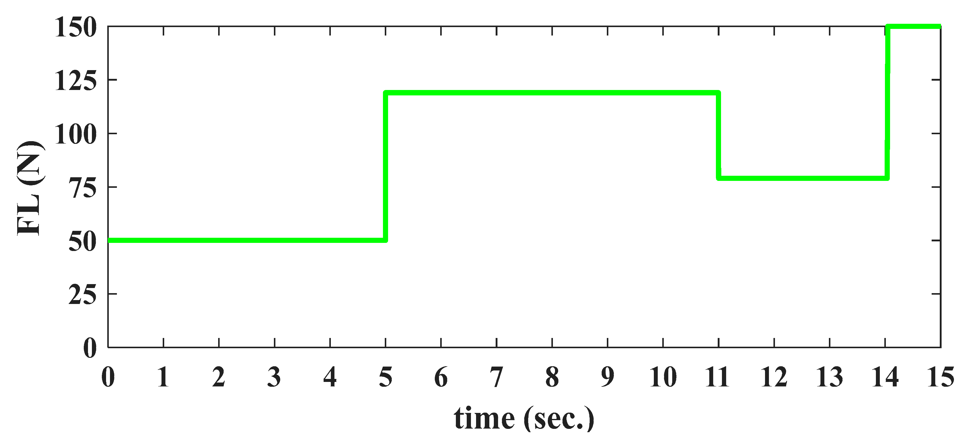
The loading behavior under variable speed operation may be defined, as shown in Figure 11. Figure 11 illustrates the sequential load variation process fed into the PLIM. For the various circumstances examined using PID and FPID controllers, the process is summarized as follows:
Period 1: The motor is operated with a light load during this period (FL = 50 N). This is the starting mode, where PLIM starts from a stop state and gradually increases in speed to the typical speed, which takes 5 s.
Period 2 (increasing load): The motor is started with a higher load (FL = 119 N) for 6 s in the period 5 to 11 s after the start.
Period 3 (reduced load): In this operating mode, the motor runs at low load (FL = 79 N) for 3 s in the period 11 to 14 s after the start.
Period 4 (full load): The motor is operated at rated load (FL = 150 N) for 1 s in the period from 14 to 15 s in this operating mode. The dynamic model parameters of PLIM are shown in Table 2.

5.2. Proposed Evaluation Indices

For each motor speed and input current, four indices of operation are used to compare the performance of the FPID to that of a traditional PID.
Steady State Error (SSE): This indicator quantifies the difference between real speed and its associated steady state values for a given portion of the operating cycle.
Oscillation Index (OI): This indicator assesses the oscillation between real rise time values and their associated stable values for a given period of the operating cycle.
Overall Steady State Value (OSSV): This indicator shows the average steady state values during the operating periods.
Rise Time Index (RTI): This indicator assesses the rising time to reach the steady state value of linear speed.
The above indices show the efficacy of the suggested FPID when compared to PID in terms of improving linear speed, input voltage, and input current waveforms and the controllers’ rapid reaction for a specific time of operation or for the entire operation cycle.

5.3. Results of Simulation Model

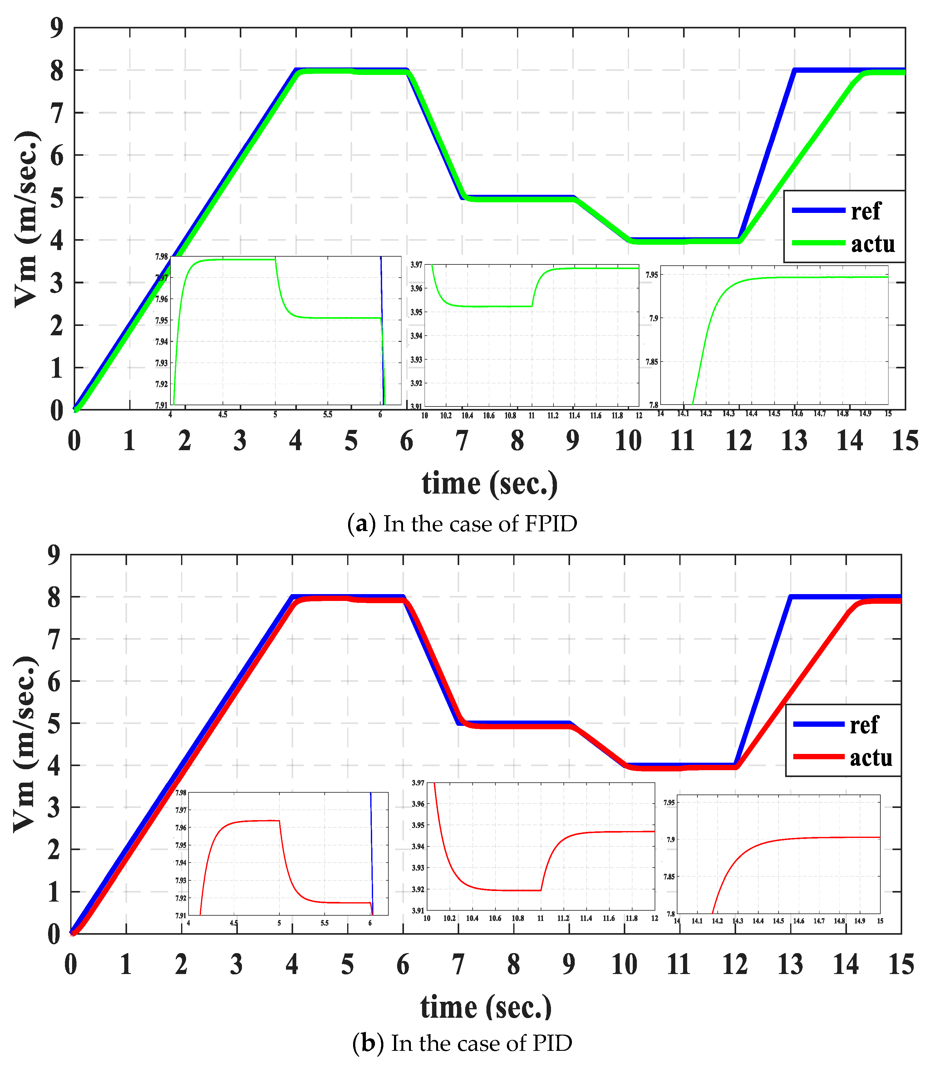
Figure 12 shows the actual speed trace of PLIM to the reference speed value using PID and FPID control. It has been established that the simulation of the system approach for determining motor operation is successful. In terms of rising time and linear speed error, the FPID controller gives better results compared to the case of using a traditional PID controller. Figure 11 shows the load force fluctuations during the four periods that will be applied to the motor that will be controlled to operate at different speed values. Compared to the PID, it was determined that the FPID tracks the reference speed more quickly with lower speed error values, and this is evident from the enlarged shots in Figure 12a,b.
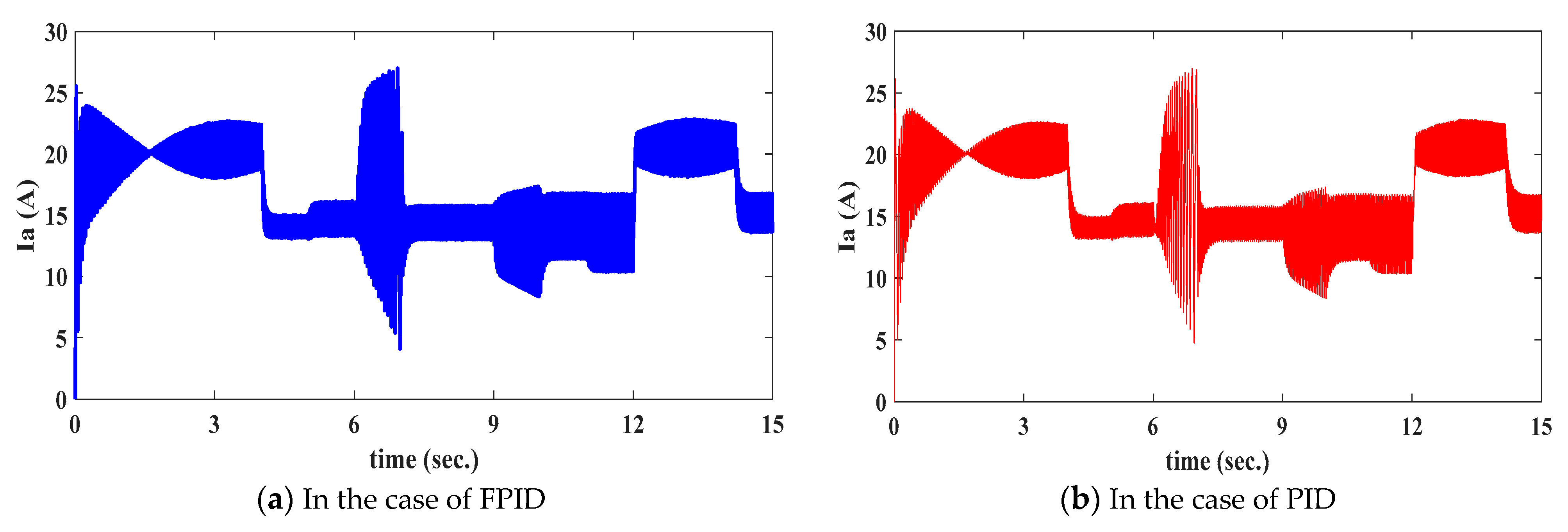
The motor input current in the first period rises gradually to its maximum value at the beginning of the instant and falls down to 13 A at a constant speed of 8 m/s, as shown in Figure 13. In the second period, the speed is lowered to 5 m/s, with a large load of 125 N and a motor current of 15 A. Figure 14 depicts the stator flux over four periods. Figure 14 shows that the stator flux value is fixed at 0.8, with some fluctuations around this value.
Figure 15 and Figure 16 clearly show the total harmonic distortion THD for input current and input voltage, respectively, under different operating conditions. Figure 15 shows clearly that the FPID reduces the overshot of the current THD at the start of the third period. The current waveform–time characteristics for the analyzed periods are depicted in Figure 17. It is also clear from the enlarged Figure 17a,b that the current in the proposed case reaches a steady state faster at a time of 7.015 s, while it reaches a steady state in the PED case at 7.035 s. This proves that the proposed case is better than PED in terms of rise time.
Figure 18 shows that Kp changes online by using FPID in the range of 2508 to 2584, Ki changes online in the range of 3 to 8.2, and Kd changes online in the range of 0.02 to 0.041. These three PID factors are varied with speed and load to give a lower error value and to enhance the motor performance.
When compared to a typical PID, the suggested FPID controller has higher profit indices, as shown in Table 3. Compared to those achieved with a traditional PID controller, the individual indices of the FPID controller have low values for all tested periods. The speed inaccuracy for the speed signs is lowered by 1.4%, from 7.978 m/s to 7.964 m/s. When compared to a traditional PID controller, the FPID controller’s rise time is lowered from 4.6 s to 4.4 s.
The following advantages of an FPID controller over a traditional one are summarized in Table 3:
  • For periods 2–4, using an FPID controller reduces speed oscillation and the resulting linear speed error.
  • When compared to the suggested FPID controller, the RTI for modes 1–4 is lowered by 4.35%, 3.85%, 2.35%, and 1.35%, respectively.
  • With a 38.9% reduction rate in the first period, the SSE for the speed signals decreased from 0.036 m/s to 0.022 m/s. When compared to a standard PID controller, the FPID controller’s rise time is lowered by 4.35%.
  • Compared to the suggested FPID controller, the OI for modes 1–4 is lowered from 30 × 10−5 m/s to 7 × 10⁻⁵ m/s in the second period.

6. Conclusions

This paper covers the implementation and comprehensive analysis of PLIM. A fuzzy-based PID coefficient tuning technique is provided to maintain the PLIM speed at a predefined reference value. A vector closed-loop controller and fuzzy PID parameter tuning have been combined for PLIM speed control. The main features of the current study are outlined as follows:
  • A mathematical model is provided to examine and study the equivalent circuit diagram for both the PLIM and DTC-SVPWM inverters.
  • A closed-loop linear motor speed control system based on fuzzy logic is provided for both high and low speed levels. The suggested FPID controller improves overall performance at over/under shoot speed, speed error, and rise time for low/high-speed working circumstances.
  • For the cycle of operation, the suggested controller FPID is evaluated for different speeds of operation under different loading conditions.
  • Four operational indices—individual steady state error, total steady state error, individual oscillation index, and total oscillation index—are used to evaluate the proposed fuzzy PID controller. The quality of the FPID compared to the PID for modes 1–4 is demonstrated by the reduction in RTI values by 4.35%, 3.85%, 2.35%, and 1.35%, respectively. With a decrease rate of 38.9% in the first period, the SSE of the velocity signals decreased from 0.036 m/s to 0.022 m/s. When comparing the rise time using the FPID compared to the PID controller, it was noted that it was reduced by 4.35%.
The use of fuzzy controllers for PLIM and the development of particle swarms [47], Improved Tasmanian devil Optimization, an interior search algorithm based on chaotic and crossover strategies, and sine-cosine optimization for fine-tuning the membership degrees, are the directions for future research. Fuzzy logic and neural networks should also be combined to provide fine tuning based on sophisticated learning methods.

Author Contributions

M.I.A. and M.M.A.; methodology, M.I.A.; validation, M.I.A. and M.M.A.; formal analysis, M.I.A.; investigation, M.I.A.; resources, M.I.A.; data curation, M.I.A. and M.M.A.; writing—original draft preparation, M.I.A.; writing—review and editing, M.I.A.; visualization, M.I.A. and F.F.M.E.-S.; supervision, M.I.A.; project administration, F.F.M.E.-S.; funding acquisition, M.I.A., F.F.M.E.-S. and M.M.A. All authors have read and agreed to the published version of the manuscript.

Funding

This study is supported via funding from Prince sattam bin Abdulaziz University project number (PSAU/2023/R/1445).

Data Availability Statement

The data presented in this study are available in this article.

Conflicts of Interest

The authors declare no conflict of interest.

Abbreviations

SymbolFull name
PLIMPoly phase linear induction machine
FPIDFuzzy PID controller
DTCDirect thrust control
PRIMPoly-phase rotary induction machines
DTC-SVMDTC with space-vector modulation
PIDProportional–integral–derivative
RTIRise time index
OSSVOverall steady state value
SSESteady state error
OIOscillation index
FOCField-oriented control

References

  1. Wang, Y.; Liu, X.; Lu, W.; Wen, T.; Yu, F.; Wu, Q. Longitudinal Dynamic End Effect of Single-Sided Linear Induction Motor for Medium–Low Speed Maglev. J. Electr. Eng. Technol. 2021, 16, 2109–2117. [Google Scholar] [CrossRef]
  2. Abdelwanis, M.I.; Zaky, A.A.; Ali, M.M. Performance study of linear induction motor fed from perovskite solar cells based on GAMPPT. In Proceedings of the 202223rd International Middle East Power Systems Conference(MEPCON), Cairo, Egypt, 13–15 December 2022; pp. 1–7. [Google Scholar]
  3. Elmorshedy, M.F.; Xu, W.; Liu, Y. Speed Control of Linear Induction Motor with Thrust and Stator Flux Ripple Reduction. In Proceedings of the 2018 21st International Conference on Electrical Machines and Systems (ICEMS), Jeju, Korea, 7–10 October 2018; pp. 1789–1794. [Google Scholar]
  4. Xu, W.; Sun, G.; Wen, G.; Wu, Z.; Chu, P.K. Equivalent Circuit Derivation and Performance Analysis of a Single-Sided Linear Induction Motor Based on the Winding Function Theory. IEEE Trans. Veh. Technol. 2012, 61, 1515–1525. [Google Scholar] [CrossRef]
  5. Hung, C.-Y.; Liu, P.; Lian, K.-Y. Fuzzy Virtual Reference Model Sensorless Tracking Control for Linear Induction Motors. IEEE Trans. Cybern. 2013, 43, 970–981. [Google Scholar] [CrossRef] [PubMed]
  6. Rizk-Allah, R.M.; Abdelwanis, M.I.; El-Sehiemy, R.A.; Abd-Elrazek, A.S. An interior search algorithm based on chaotic and crossover strategies for parameter extraction of poly phase induction machines. Neural Comput. Appl. 2022, 35, 6647–6664. [Google Scholar] [CrossRef]
  7. Abdelwanis, M.I. Linear Induction Motor Parameter Estimation Based on Gray Wolves Optimization Algorithm. In Proceedings of the 2022 23rd International Middle East Power Systems Conference (MEPCON), Cairo, Egypt, 13–15 December 2022; pp. 1–6. [Google Scholar]
  8. Elmorshedy, M.F.; Almakhles, D.J.; El-Sousy, F.F. Modified primary flux linkage for enhancing the linear induction motor performance based on sliding mode control and model predictive flux control. IEEE Access 2003, 11, 26184–26198. [Google Scholar] [CrossRef]
  9. Zheng, Y.; Cao, Z.; Wang, S.; Man, Z.; Chuei, R. Extreme learning machine-based field-oriented feedback linearization speed control of permanent magnetic synchronous motors. Neural Comput. Appl. 2022, 34, 5267–5282. [Google Scholar] [CrossRef]
  10. Boucheta, A.; Bousserhane, I.K.; Hazzab, A.; Sicard, P.; Fellah, M.K. Speed Control of Linear Induction Motor using SlidingMode Controller Considering the End Effects. J. Electr. Eng. Technol. 2012, 7, 34–45. [Google Scholar] [CrossRef]
  11. Zou, J.; Xu, W.; Yu, X.; Liu, Y.; Ye, C. Multistep Model Predictive Control with Current and Voltage Constraints for Linear Induction Machine Based Urban Transportation. IEEE Trans. Veh. Technol. 2017, 66, 10817–10829. [Google Scholar] [CrossRef]
  12. Ali, M.M.; Xu, W.; Elmorshedy, M.F.; Liu, Y.; Dong, M. An Improved Finite-Set Model Predictive Current Control with Nonlinear Speed Regulator for Linear Induction Machine based on Linear Metro. In Proceedings of the 2020 IEEE Energy Conversion Congress and Exposition (ECCE), Detroit, MI, USA, 11–15 October 2020; pp. 5141–5147. [Google Scholar]
  13. Abdelfatah, N.; Brahim, G. A Novel Lithium Ion Battery Autonomous Strategy Improvement Based on SVM-DTC for Urban Electric Vehicle under Several Speeds Tests. Majlesi J. Electr. Eng. 2011, 5, 40–45. [Google Scholar]
  14. Karuppannan, A.; Muthusamy, M. Wavelet neural learning-based type-2 fuzzy PID controller for speed regulation in BLDC motor. Neural Comput. Appl. 2021, 33, 13481–13503. [Google Scholar] [CrossRef]
  15. Zhou, H.; Chen, R.; Zhou, S.; Liu, Z. Design and Analysis of a Drive System for a Series Manipulator Based on Orthogonal-Fuzzy PID Control. Electronics 2019, 8, 1051. [Google Scholar] [CrossRef]
  16. Xu, W.; Ali, M.M.; Elmorshedy, M.F.; Allam, S.M.; Mu, C. One Improved Sliding Mode DTC for Linear Induction Machines Based on Linear Metro. IEEE Trans. Power Electron. 2021, 36, 4560–4571. [Google Scholar] [CrossRef]
  17. Xu, W.; Zhu, J.G.; Zhang, Y.; Li, Y.; Wang, Y.; Guo, Y. An improved equivalent circuit model of a single-sided linear induction motor. IEEE Trans. Veh. Technol. 2010, 59, 2277–2289. [Google Scholar] [CrossRef]
  18. Chandrasekaran, S.; Durairaj, S.; Padmavathi, S. A Performance Improvement of the Fuzzy Controller-Based Multi- Level Inverter-Fed Three-Phase Induction Motor with Enhanced Time and Speed of Response. J. Electr. Eng. Technol. 2021, 16, 1131–1141. [Google Scholar] [CrossRef]
  19. Du, L.; Lu, X.; Yu, M.; Dong, B.; Li, Y. Experimental Investigation on Fuzzy PID Control of Dual Axis Turntable Servo System. Procedia Comput. Sci. 2018, 131, 531–540. [Google Scholar] [CrossRef]
  20. Mohan, V.; Chhabra, H.; Rani, A.; Singh, V. An expert 2 DOF fractional order fuzzy PID controller for nonlinear systems. Neural Comput. Appl. 2019, 31, 4253–4270. [Google Scholar] [CrossRef]
  21. Nithilasaravanan, K.; Thakwani, N.; Mishra, P.; Kumar, V.; Rana, K.P.S. Efficient control of integrated power system using self-tuned fractional-order fuzzy PID controller. Neural Comput. Appl. 2019, 31, 4137–4155. [Google Scholar] [CrossRef]
  22. Kudinov, Y.I.; Kolesnikov, V.A.; Pashchenko, F.F.; Pashchenko, A.F.; Papic, L. Optimization of Fuzzy PID Controller’s Parameters. Procedia Comput. Sci. 2017, 103, 618–622. [Google Scholar] [CrossRef]
  23. Wang, Y.; Jin, Q.; Zhang, R. Improved fuzzy PID controller design using predictive functional control structure. ISA Trans. 2017, 71, 354–363. [Google Scholar] [CrossRef]
  24. Verma, O.P.; Manik, G.; Jain, V.K. Simulation and control of a complex nonlinear dynamic behavior of multi-stage evaporator using PID and Fuzzy-PID controllers. J. Comput. Sci. 2018, 25, 238–251. [Google Scholar] [CrossRef]
  25. Ustun, S.; Demirtas, M. Optimal tuning of PI coefficients by using fuzzy-genetic for V/f controlled induction motor. Expert Syst. Appl. 2008, 34, 2714–2720. [Google Scholar] [CrossRef]
  26. Ranjbar, N.A.; Kholerdi, H.A. Chaotification and fuzzy PI control of three-phase induction machine using synchronization approach. Chaos Solitons Fractals 2016, 91, 443–451. [Google Scholar] [CrossRef]
  27. Wang, Y.; Yu, Y.; Zhang, G.; Sheng, X. Fuzzy Auto-adjust PID Controller Design of Brushless DC Motor. Phys. Procedia 2012, 33, 1533–1539. [Google Scholar] [CrossRef]
  28. Fathy, A.; Kassem, A.M.; Abdelaziz, A.Y. Optimal design of fuzzy PID controller for deregulated LFC of multi-area power system via mine blast algorithm. Neural Comput. Appl. 2020, 32, 4531–4551. [Google Scholar] [CrossRef]
  29. Kumar, J.; Kumar, V.; Rana, K.P.S. Fractional-order self-tuned fuzzy PID controller for three-link robotic manipulator system. Neural Comput. Appl. 2020, 32, 7235–7257. [Google Scholar] [CrossRef]
  30. deAlmeida, J.F.M.; Valdenebro, L.R.; Bin, E. Fuzzy logic based maximum torque control for asingle-phase induction motor. In Proceedings of the 25th Annual Conference of the IEEE Industrial Electronics Society (Cat. No. 99CH37029), SanJose, CA, USA, 29 November–3 December 1999; Volume 2, pp. 619–624. [Google Scholar]
  31. Ozkop, E.; Akpinar, A.S.; Okumus, H.I. Direct torque control for Linear Induction Motor. In Proceedings of the 12th International Middle-East Power System Conference, Aswan, Egypt, 12–15 March 2008; pp. 373–376. [Google Scholar]
  32. Wang, D. Sensorless Fuzzy Variable Speed Control with Torque Optimization for the Improvements of Single Phase Capacitor-RunInduction Motors. In Proceedings of the 2010 International Conference on Measuring Technology and Mechatronics Automation, Changsha, China, 13–14 March 2010; pp. 325–328. [Google Scholar]
  33. Bouhoune, K.; Yazid, K.; Boucherit, M.S. Hybrid neural-fuzzy control of the single-phase induction machine. In Proceedings of the 2011 International Conference on Communications, Computing and Control Applications (CCCA), Hammamet, Tunisia, 3–5 March 2011; pp. 1–5. [Google Scholar]
  34. Chen, D.; Fang, Z.; Li, S. A Novel BSO Algorithm for Three-Layer Neural Network Optimization Applied to UAV Edge Control. Neural Process. Lett. 2023, 55, 1–20. [Google Scholar] [CrossRef]
  35. Nanda, A.B.; Bhattacharya, T.K. High performance vector control of single phase induction motor drives based on rotorMEMF. In Proceedings of the 2011 International Conference on Energy, Automation and Signal, Bhubaneswar, India, 28–30 December 2011; pp. 1–5. [Google Scholar]
  36. Chhabra, H.; Mohan, V.; Rani, A.; Singh, V. Robust nonlinear fractional order fuzzy PD plus fuzzy I controller applied to robotic manipulator. Neural Comput. Appl. 2020, 32, 2055–2079. [Google Scholar] [CrossRef]
  37. Bhandari, K.S.; Cho, G.H. A resource Oriented Route Selection Framework Using Contextual Information Based on Fuzzy Logic. Electronics 2019, 8, 1023. [Google Scholar] [CrossRef]
  38. Lin, F.-J.; Wai, R.-J. Hybrid control using recurrent fuzzy neural network for linear induction motor servo drive. IEEE Trans. Fuzzy Syst. 2001, 9, 102–115. [Google Scholar] [CrossRef]
  39. Elmorshedy, M.F.; Xu, W.; Ali, M.M.; Liu, Y.; Allam, S.M. High Performance Speed Sensorless Finite-Set Predictive Thrust Control of a Linear Induction Motor based on MRAS and Fuzzy Logic Controller. In Proceedings of the 2020 IEEE 9th International Power Electronics and Motion Control Conference (IPEMC2020-ECCE Asia), Nanjing, China, 29 November–2 December 2020; pp. 3039–3044. [Google Scholar]
  40. Xu, W.; Zhu, J.G.; Zhang, Y.; Li, Z.; Li, Y.; Wang, Y.; Guo, Y.; Li, Y. Equivalent Circuits for Single-Sided Linear Induction Motors. IEEE Trans. Ind. Appl. 2010, 46, 2410–2423. [Google Scholar] [CrossRef]
  41. Yu, H.; Fahimi, B. A Direct Control Scheme to Achieve Maximum Acceleration in Linear Induction Motors. In Proceedings of the IEEE International Electric Machines & Drives Conference, Antalya, Turkey, 3–5 May 2007; pp. 977–982. [Google Scholar] [CrossRef]
  42. Wogi, L.; Ayana, T.; Morawiec, M.; Jąderko, A. A Comparative Study of Fuzzy SMC with Adaptive Fuzzy PID for Sensorless Speed Control of Six-Phase Induction Motor. Energies 2022, 15, 8183. [Google Scholar] [CrossRef]
  43. Hu, Q.; Yu, H.; Mu, Y.; Yao, F.; Zhang, X. A novel fuzzy PID velocity control of linear elevator driven by the permanent magnet linear synchronous motor. In Proceedings of the 2008 International Conference on Electrical Machines and Systems, Wuhan, China, 17–20 October 2008; pp. 1539–1542. [Google Scholar]
  44. Tao, Y.; Zheng, J.; Lin, Y.; Wang, T.; Xiong, H.; He, G.; Xu, D. Fuzzy PID control method of deburring industrial robots. J. Intell. Fuzzy Syst. 2015, 29, 2447–2455. [Google Scholar] [CrossRef]
  45. Yun, J.; Sun, Y.; Li, C.; Jiang, D.; Tao, B.; Li, G.; Liu, Y.; Chen, B.; Tong, X.; Xu, M. Self-adjusting force/bit blending control based on quantitative factor-scale factor fuzzy-PID bit control. Alex. Eng. J. 2022, 61, 4389–4397. [Google Scholar] [CrossRef]
  46. Barakat, M. Optimal design of fuzzy-PID controller for automatic generation control of multi-source interconnected power system. Neural Comput. Appl. 2022, 34, 18859–18880. [Google Scholar] [CrossRef]
  47. Abdelwanis, M.I.; El-Sehiemy, R.A.; Hamida, M.A. Parameter estimation of permanent magnet synchronous machines using particle swarm optimization algorithm. Rev. Roum. Sci. Techn.-Électrotechn. Énerg. 2022, 67, 377–382. [Google Scholar]
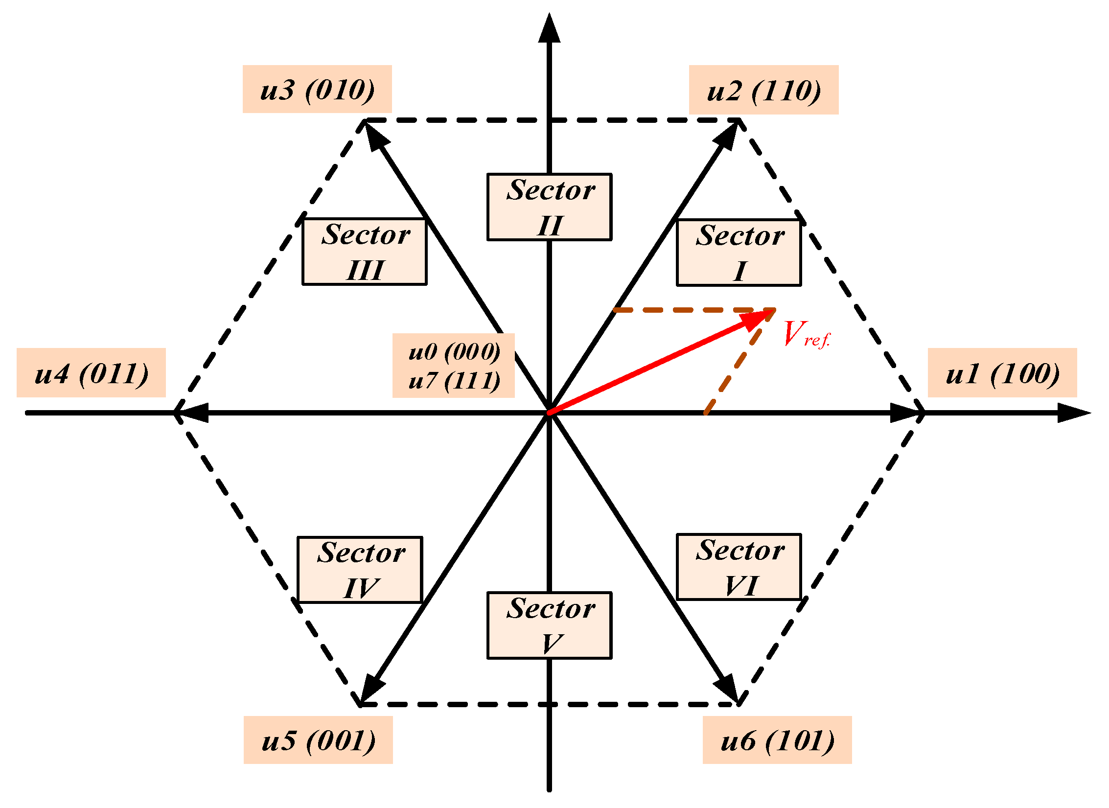
Figure 1. SVM for voltage vector of stator reference.
Electronics 12 04955 g001
Figure 2. αβ axis of stator and movable flux linkage vectors.
Electronics 12 04955 g002
Figure 3. Selecting the optimal voltage vector depends on the needed thrust and flux.
Electronics 12 04955 g003
Figure 4. The suggested FPID closed loop’s schematic design.
Electronics 12 04955 g004
Figure 5. Basic procedure of FPID.
Electronics 12 04955 g005
Figure 6. Modelling of fuzzy-based PID tuning.
Electronics 12 04955 g006
Figure 7. Error and change in error (input variables) of fuzzy system. Note: NG (negative big); ND (negative medium); NM (negative small); O (zero); SM (positive small); SD (positive medium); SG (positive big).
Electronics 12 04955 g007
Figure 8. Fuzzy modeling for PID coefficients Kp’ and Kd. Note: M (small); G (big).
Electronics 12 04955 g008
Figure 9. Weighting coefficient βi of fuzzy system. Note: RM (large small); M (small); G (big); RG (large big).
Electronics 12 04955 g009
Figure 10. MATLAB/Simulink schematic diagram of the PLIM system.
Electronics 12 04955 g010
Figure 11. Load force–time characteristics.
Electronics 12 04955 g011
Figure 12. PLIM linear speed characteristics.
Electronics 12 04955 g012
Figure 13. Primary current characteristics of PLIM.
Electronics 12 04955 g013
Figure 14. Motor flux linkage characteristics.
Electronics 12 04955 g014
Figure 15. THD in input current versus time.
Electronics 12 04955 g015
Figure 16. THD in input voltage versus time.
Electronics 12 04955 g016
Figure 17. Primary current waveform versus time.
Electronics 12 04955 g017
Figure 18. PID parameters (Kp, Ki, and Kd) tuned by fuzzy control.
Electronics 12 04955 g018
Table 1. Fuzzy rules truth table for the suggested FPID controller.
ercekpkdβierceKpkdβi
NG, SGNGGMRMNM, SMNGMGG
NDGMRMNDMGM
NMGMRMNMGGM
OGMRMOGMRM
SMGMRMSMGGM
SDGMRMSDMGM
SGGMRMSGMGG
ND, SDNGMGMONGMGRG
NDGGMNDMGG
NMGMRMNMMGM
OGMRMOGGM
SMGMRMSMMGM
SDGGMSDMGG
SGGGMSGMGRG
Table 2. PLIM motor parameters.
ParameterValueParameterValue
Input voltage, UN180 Vkp2114.5
Motor current, IN22 Aki3.59
motor speed, vN11 m/skd0.0
Resistance of Primary, Ra1 Ωkp13000
Resistance of Secondary, Rb2.4 Ωki150
Secondary leakage inductance, Llb0.0043 Hkd10.0
leakage inductance of Primary, Lla0.0114 Hkp21000
Primary Pole pitch, τ0.1485 mki25
Length of Primary, ls1.3087 mkd20.0
Motor power, PN3 kWSample time Ts1 × 10−5 s
Thrust force, FN280 Nψa*0.8
Table 3. Indices of optimized FPID against PID controllers for linear speed.
PeriodIndexPIDFPID
1RTI sec4.65.54.45.38
OSSV m/s7.9647.9177.9787.951
OI m/s6 × 10−512 × 10−54 × 10−58 × 10−5
SSE m/s0.0360.0830.0220.049
2RTI sec7.8 7.5
OSSV m/s4.9184.952
OI m/s30 × 10−57 × 10−5
SSE m/s0.0820.048
3RTI sec10.6511.610.411.4
OSSV m/s3.91933.94683.95233.9683
OI m/s14 × 10−511 × 10−512 × 10−510 × 10−5
SSE m/s0.08070.05320.04770.0317
4RTI sec14.8 14.6
OSSV m/s7.90277.9468
OI m/s15 × 10−59 × 10−5
SSE m/s0.09730.0532
Disclaimer/Publisher’s Note: The statements, opinions and data contained in all publications are solely those of the individual author(s) and contributor(s) and not of MDPI and/or the editor(s). MDPI and/or the editor(s) disclaim responsibility for any injury to people or property resulting from any ideas, methods, instructions or products referred to in the content.