Article

Using the Displaced Phase Center Azimuth Multiple Beams Technique with Spaceborne Synthetic Aperture Radar Systems for Multichannel Reconstruction of Accelerated Moving Targets

1
College of Information Engineering, Inner Mongolia University of Technology, Hohhot 010051, China
2
Inner Mongolia Key Laboratory of Radar Technology and Application, Hohhot 010051, China
*
Author to whom correspondence should be addressed.
Electronics 2023, 12(24), 4954; https://doi.org/10.3390/electronics12244954
Submission received: 2 November 2023 / Revised: 4 December 2023 / Accepted: 6 December 2023 / Published: 10 December 2023
(This article belongs to the Special Issue New Insights in Radar Imaging)

Abstract

:
The displaced phase center multiple azimuth beams (DPCMAB) technique can help spaceborne synthetic aperture radar (SAR) systems obtain the high-resolution wide-swath (HRWS) imaging capacity, and azimuth multichannel reconstruction is usually required due to azimuth non-uniform sampling. Compared with stationary and moving targets, the range history and azimuth signal model of the moving target with an acceleration are obviously different. The azimuth multichannel signal model of an accelerated moving target is established, and the relationship between acceleration and Doppler parameters is analyzed. Furthermore, the impact of the acceleration on azimuth multichannel reconstruction and imaging results is simulated and analyzed. According to the azimuth multichannel signal model, an azimuth multichannel reconstruction approach for accelerated moving targets is proposed. The key point of the proposed reconstruction approach is the modified azimuth multichannel matrix, which is related not only to azimuth and slant velocities but also accelerations. The target’s velocities and accelerations are obtained using multiple Doppler parameter estimations. Compared with the conventional method of processing the raw data of accelerated moving targets, this proposed method could distinctly suppress image defocusing and pairs of false targets. Simulation results on point targets validate the proposed azimuth multichannel reconstruction approach.

1. Introduction

High-resolution wide-swath (HRWS) is an irreconcilable contradiction in the traditional spaceborne synthetic aperture radar (SAR) system [1,2,3,4]. Constrained by the minimum antenna area, spaceborne SAR cannot simultaneously obtain azimuthal high-resolution and wide-swath [5]. The azimuthal high resolution is determined by the Doppler bandwidth. To avoid azimuthal Doppler spectrum aliasing it is required to raise the pulse repetition frequency (PRF), whereas the wide-swath depends on the pulse repetition interval such that the PRF needs to be decreased to prevent range ambiguity. The result is that the wide-swath and azimuthal high-resolution cannot be obtained together [6]. The displaced phase center multiple azimuth beams (DPCMAB) technique [7] effectively resolves a conflict between width-swath and resolution. The technique can increase the sampling rate to several times that of the transmitted pulse while transmitting a lower pulse repetition frequency, thereby meeting the requirement of high-resolution imaging.
Limited by the geometric relationship of spaceborne SAR imaging and the timing diagram selection of radar signal transmission and reception, the system PRF corresponding to some wave positions will seriously deviate from the ideal uniform sampling PRF. The result is that the equivalent phase center (EPC) of the received signal is unevenly distributed [8]. Direct processing will form strong false targets in azimuth, which will significantly affect SAR image quality and amplify the ambiguity energy in azimuth [9]. Therefore, azimuth multichannel reconstruction is performed before image processing to solve the non-uniform sampling problem [10,11]. For stationary targets, Gerhard Krieger proposed an azimuth multichannel SAR system spectrum reconstruction filter bank algorithm based on the generalized sampling theorem [12], which achieves unambiguous reconstruction of the azimuth spectrum caused by aliasing due to nonuniformity [13]. Yongzhen Guo proposed an algorithm to eliminate azimuthal signal ambiguity by converting bi-static data into mono-static data [14]. However, these methods are only applicable to stationary scenes and cannot effectively reconstruct echo data when moving targets exist. Therefore, imaging algorithms for moving targets under azimuthal multichannel were investigated. Based on the beamforming principles, Stefan V. Baumgartner proposed the matched reconstruction filter bank algorithm (MRFB) and successfully achieved spectrum reconstruction of moving targets for the first time [15]. Aiming to tackle the problem that moving targets in sea scenes can lead to false targets in SAR reconstructed images, an AMC-HRWS SAR algorithm for unblurred imaging of moving targets was proposed in [16] to eliminate the false targets generated by the range velocity error. However, most of the literature studying moving targets on the ground and ships at sea usually assumes that targets move at a constant velocity [17,18,19]. When monitoring sea and road traffic, it is important to take into account that moving targets often accelerate.
Conventional moving target imaging methods assume that the target moves in a uniform linear motion within synthetic aperture time; through estimating the first and second phases of the echo spectrum, the velocity component of the moving target is inverted and then refocused [20]. In actual situations, the target trajectory is complex, and ignoring even small accelerations will cause serious errors when estimating the velocity [21,22,23]. To systematically and scientifically study the potential effects of acceleration on detection and focusing, Jayanti Sharma [24] first studied the effect of acceleration on the detection and estimation velocity of ground-moving targets and found that acceleration seriously impacts focusing. The quadratic phase error generated by the acceleration of the moving target will lead the target to defocus, which will seriously impact the accuracy of signal reconstruction. To reduce the impact of phase error, a moving target imaging method based on map drift subspace is proposed in [25] to compensate for phase error and improve signal reconstruction accuracy. For the problem of acceleration estimation, a theory and method for compensating along-track acceleration were proposed in [26], which improves the accuracy of acceleration estimation by using the phase derivative in the Doppler frequency domain. Compared with stationary and moving targets, the range history and azimuth signals of moving targets with acceleration are significantly different. This paper establishes a geometric model of accelerated moving targets in azimuth multichannel SAR and analyzes the relationship between acceleration and Doppler parameters and the impact of acceleration on the quality of azimuth multichannel reconstruction image. A multichannel reconstruction method for accelerated moving targets is proposed, which eliminates the azimuth channel imbalance caused by acceleration by correcting the azimuth multichannel matrix. A fast estimation and search method for the acceleration velocity of moving targets in spaceborne azimuth multichannel SAR mode is given.
This paper is organized as follows: The azimuthal multichannel geometric imaging model for accelerated moving targets is derived and the impact of acceleration on azimuthal multichannel imaging is analyzed in Section 2. Section 3 proposes an azimuth multichannel reconstruction method based on the accelerated moving target echo model and introduces a velocity estimation method. Simulation experiments of point targets are conducted to verify the effectiveness of the proposed method in Section 4. The conclusions of this paper are reported in Section 5.

2. Signal Model

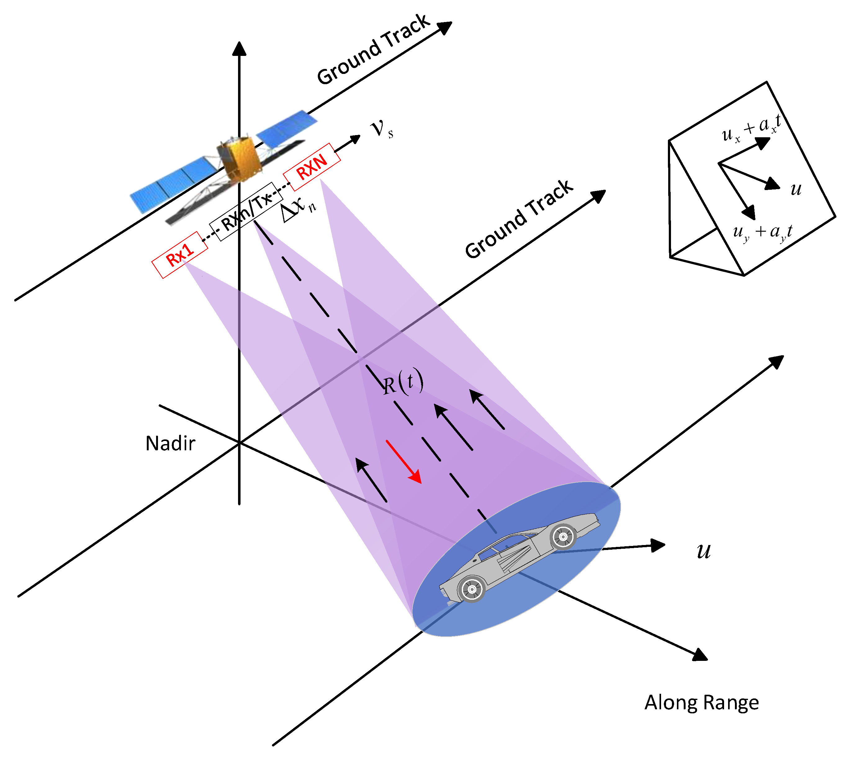
2.1. Geometric Model of Moving Targets

The structure of the spaceborne azimuth multichannel SAR accelerated moving target imaging geometric model is shown in Figure 1. A motion model is established in three-dimensional space and decomposes the motion parameters of the moving target into four components: along-track velocity u x , along-track acceleration a x , slant range velocity u y , and slant range acceleration a y . Although the difficulty of the problem has increased, it is more general. The satellite moves along the track at velocity v s . The entire antenna is divided into n sub-apertures along the azimuthal direction, with the center channel transmitting the signal and all channels receiving the echo signal. Δ x n is the distance between the n-th receive channel and the transmit phase center.
Moving targets are different from stationary targets because they have additional motion relative to the radar platform. From Figure 1, the slant distance R T ( t ) between the satellite launch center and the moving target can be expressed as:
R T ( t ) = R 0 + u y t + 1 2 a y t 2 2 + v s t u x t 1 2 a x t 2 2
where R 0 is the shortest distance from the received echo phase center to the moving target imaging and t is the azimuth time.
Expanding Equation (1) into a Taylor series, considering the presence of acceleration and retaining the expanded term of t 3 , results in the following expression:
R T ( t ) = R 0 + u y t + 1 2 a y t 2 + ( v s u x ) 2 2 R 0 + u y t + 1 2 a y t 2 t 2 a x ( v s u x ) 2 R 0 + u y t + 1 2 a y t 2 t 3
Similar to (1), when the satellite receives the echo, the slant distance R n ( t ) between the channel and the moving target is obtained, which can be defined as:
R n ( t ) = R 0 + u y t + 1 2 a y t 2 2 + v s t u x t 1 2 a x t 2 Δ x n 2
Using the Taylor series expansion of (3), the slant range history is written as follows:
R n ( t ) = R 0 + u y t + 1 2 a y t 2 Δ x n ( v s u x ) R 0 + v y t + 1 2 a y t 2 t + ( v s u x ) 2 + Δ x n a x 2 R 0 + u y t + 1 2 a y t 2 t 2 a x ( v s u x ) 2 R 0 + u y t + 1 2 a y t 2 t 3 + Δ x n 2 2 R 0 + u y t + 1 2 a y t 2
By combining (2) with (4) we can obtain the following expression:
R total = R T ( t ) + R n ( t ) = 2 R 0 + Δ x n 2 2 R 0 + u y t + 1 2 a y t 2 + 2 u y R 0 ( v s u x ) Δ x n R 0 + u y t + 1 2 a y t 2 t + 2 u y 2 + 2 ( v s u x ) 2 + 2 a y R 0 + a x Δ x n 2 R 0 + u y t + 1 2 a y t 2 t 2 + a y u y a x ( v s u x ) R 0 + u y t + 1 2 a y t 2 t 3
Since the synthetic aperture time is R 0 u y t + 1 2 a y t 2 , the approximated expression in (5) becomes:
R total = R T ( t ) + R n ( t ) = 2 R 0 + Δ x n 2 2 R 0 + 2 u y R 0 ( v s u x ) Δ x n R 0 t + 2 u y 2 + 2 ( v s u x ) 2 + 2 a y R 0 + a x Δ x n 2 R 0 t 2 + a y u y a x ( v s u x ) R 0 t 3
For a moving target under illumination, the baseband radar echo received by the n-th receiving sub-aperture is formulated as:
s n ( τ , t ) = A 0 ω r τ R T ( t ) + R n ( t ) c ω a ( t ) exp j 2 π λ R T ( t ) + R n ( t ) exp j π K r τ R T ( t ) + R n ( t ) c 2 r e c t τ R T ( t ) + R n ( t ) / c τ p
where A 0 is a complex constant, c is the light speed, τ is the range time, ω r ( ) and ω a ( ) represent the received and transmitted echo pulse envelopes, respectively, λ is the wavelength, K r is the transmit pulse repetition frequency, and τ p is the transmit pulse duration.
This paper focuses on multichannel reconstruction in azimuth. Then, the signal component of (7) is provided as follows:
s mov , n ( t ) = exp j 2 π λ R T ( t ) + R n ( t )
By substituting (6) into (8), the echo signal after range compression is given as:
s mov , n ( t ) exp j 4 π λ R 0 exp j π λ Δ x n 2 R 0 exp j 2 π λ 2 u y R 0 v s u x Δ x n R 0 t exp j 2 π λ 2 u y 2 + 2 v s u x 2 + 2 a y R 0 + a x Δ x n 2 R 0 t 2 exp j 2 π λ a y u y a x v s u x R 0 t 3

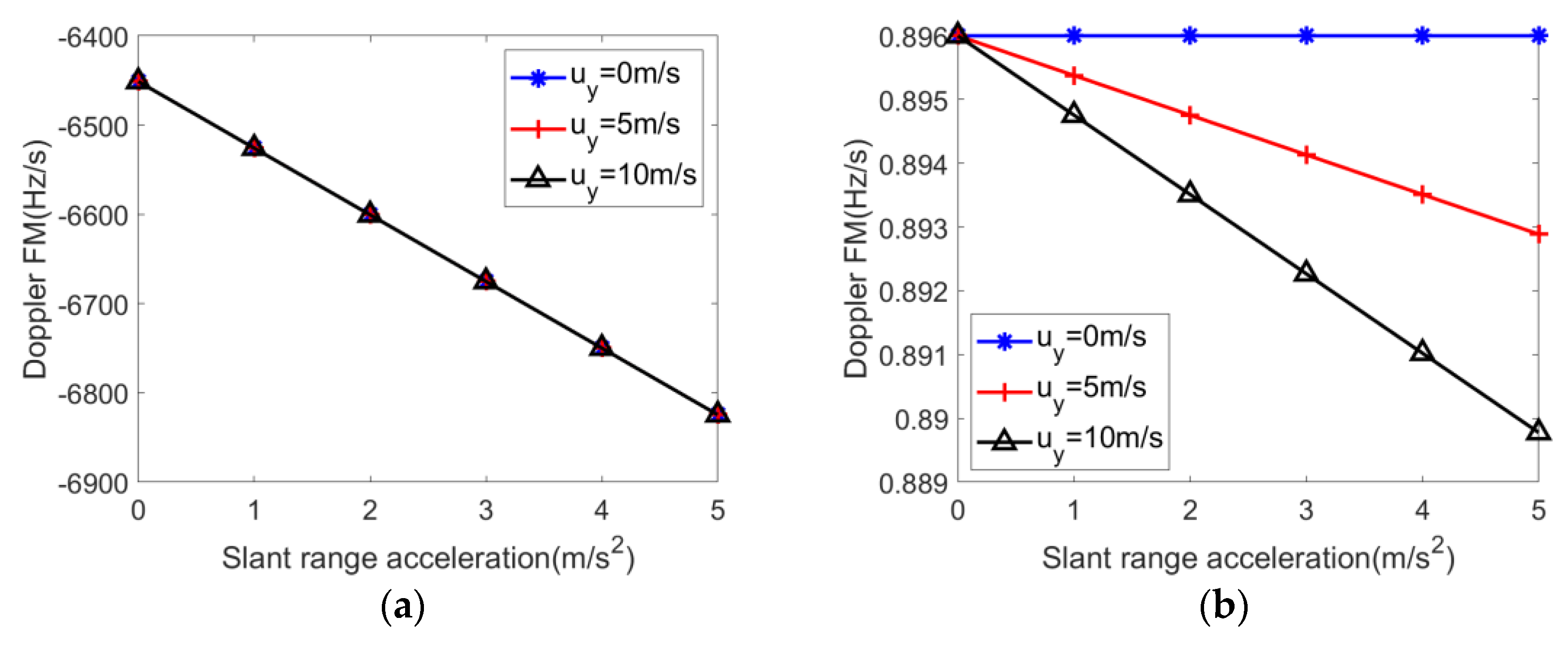
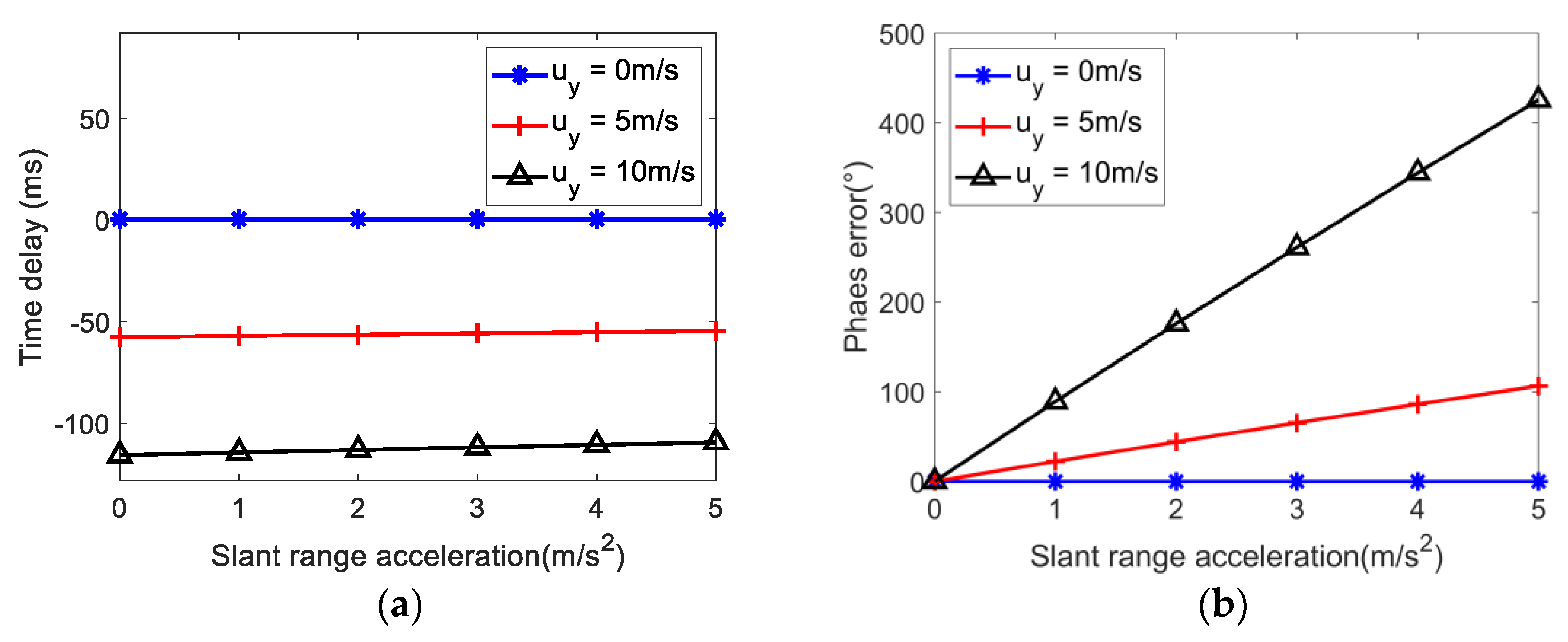
2.2. Acceleration Impact Analysis

The Doppler center f d c generated by the slant range velocity of the moving target is:
f d c = 2 u y λ
The Doppler second-order frequency modulation k a , 2 caused by slant range velocity and slant range acceleration can be written as follows:
k a , 2 = 2 λ 2 u y 2 + 2 ( v s u x ) 2 + 2 a y R 0 R 0
The Doppler third-order frequency modulation k a , 3 can be expressed as:
k a , 3 = 4 λ a y u y a x ( v s u x ) R 0
Figure 2 illustrates the effect of slant range acceleration on the second-order and higher-order parameters of the Doppler frequency modulation. Figure 2a shows that Doppler frequency modulation is very sensitive to slant range acceleration, with the frequency modulation changing by 100 Hz/s for every 1 m/s2 change in slant range acceleration. Figure 3 illustrates the impact of slant range velocity on second-order and third-order Doppler frequency modulation parameters. Figure 3a shows that the slant range velocity does not change the Doppler frequency modulation under the influence of slant range acceleration. Comparing Equations (11) and (12), the Doppler third-order frequency has v s u x u y , so the influence of a x is greater than a y . However, compared with the influence of the second-order frequency modulation parameter a y , the influence of a x can be ignored.

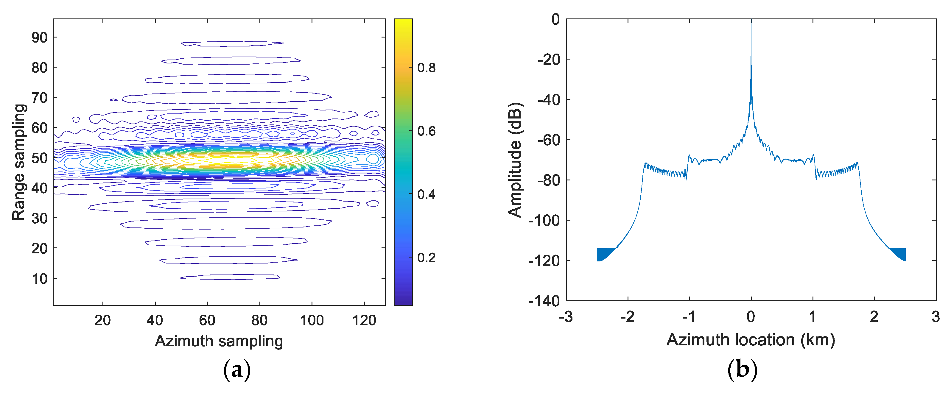
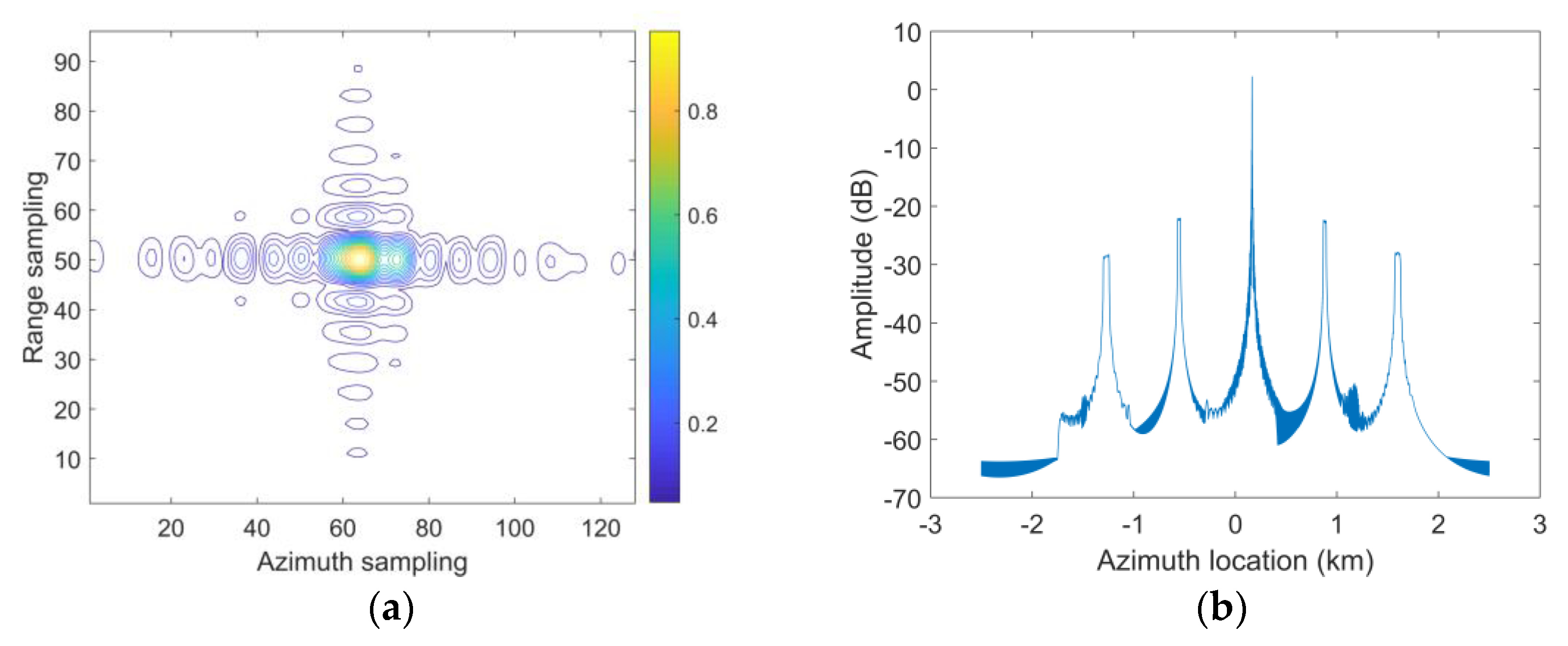
2.3. Effect of Acceleration on Imaging Results

To verify the previous analysis, this section uses a conventional multichannel reconstruction method to simulate point targets with acceleration. The impacts of along-track acceleration and slant range acceleration on moving target imaging were analyzed, respectively. The simulation parameters used in this research are listed in Table 1.
After the conventional multichannel reconstruction approach is processed, the results of capturing point target images with different moving velocities, as shown in Figure 4 and Figure 5. Figure 4a,b show the interpolated contour plots and the maximum azimuth profile of a point target with an along-track velocity of 10 m/s and an along-track acceleration of 5 m/s2, which causes image defocus. The amplitude of false targets caused by along-track acceleration is small or even negligible. Figure 5a,b represent a moving target traveling at a slant range velocity of 10 m/s and a slant range acceleration of 5 m/s2. There are obvious false targets in the imaging results. To address this phenomenon, this paper proposes an azimuthal multichannel reconstruction method.

3. Azimuth Multichannel Reconstruction

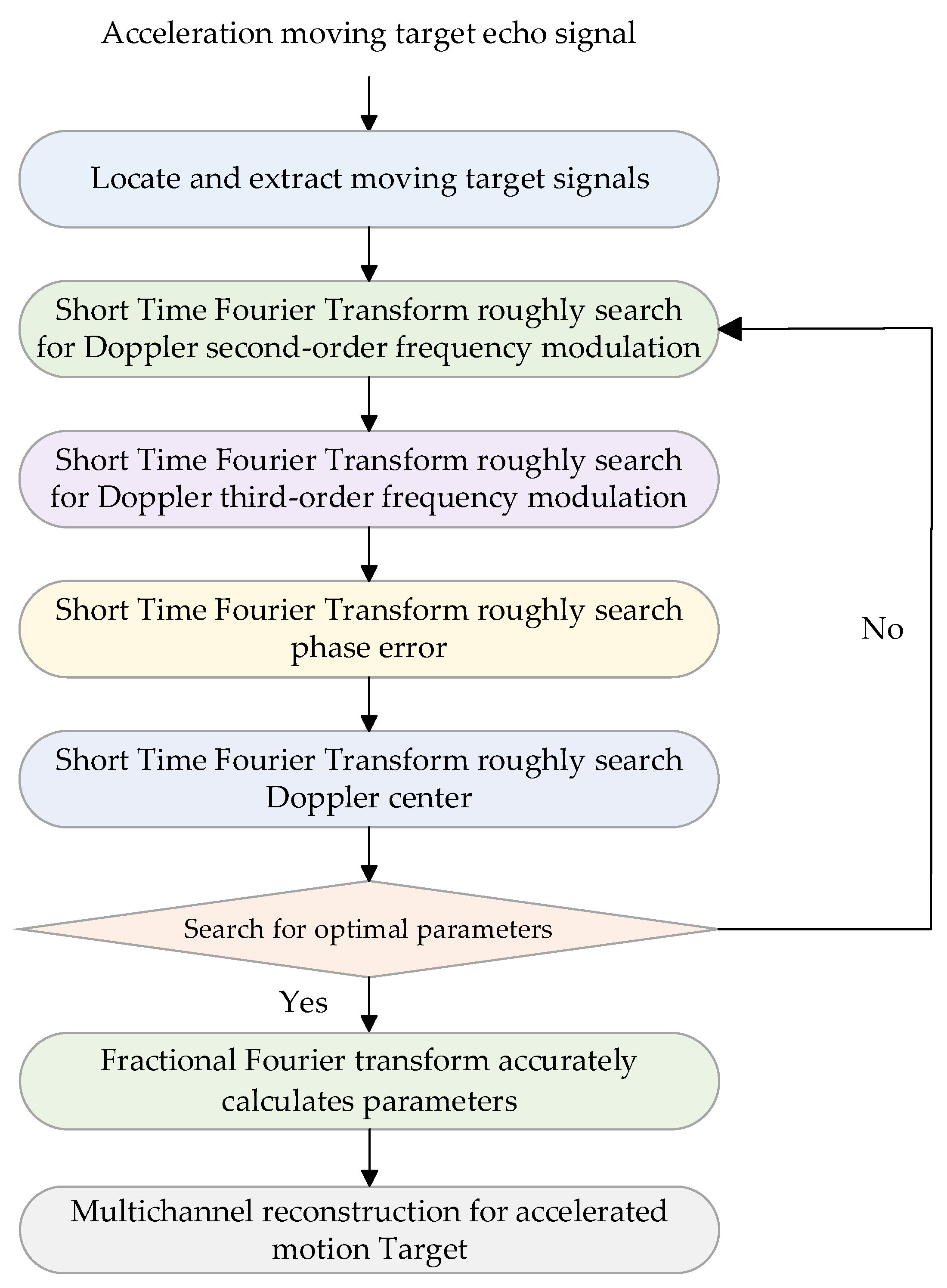
3.1. Moving Target Imaging Method

When processing echo signals, the multichannel reconstruction processing algorithm only needs to take into account t 2 [27], so the expression of Equation (9) can be approximated as:
s mov , n ( t ) exp j 4 π λ R 0 exp j π λ Δ x n 2 R 0 exp j 2 π λ 2 u y 2 + 2 ( v s u x ) 2 + 2 a y R 0 + a x Δ x n 2 R 0 t ( v s u x ) Δ x n 2 u y R 0 2 u y 2 + 2 ( v s u x ) 2 + 2 a y R 0 + a x Δ x n 2 exp j π λ ( v s u x ) 2 Δ x n 2 4 u y ( v s u x ) R 0 Δ x n + 4 u y 2 R 0 2 R 0 2 u y 2 + 2 ( v s u x ) 2 + 2 a y R 0 + a x Δ x n
The derivation of Equation (13) is in Appendix A. Comparing the azimuth impulse responses of stationary targets and moving targets, the differences are mainly reflected in two aspects: time delay Δ t n and phase error Δ φ n . These differences can be expressed as follows:
Δ t n = ( v s u x ) Δ x n 2 u y R 0 2 u y 2 + 2 ( v s u x ) 2 + 2 a y R 0 + a x Δ x n
Δ φ n = π Δ x n 2 λ R 0 + 2 π λ ( v s u x ) 2 Δ x n 2 4 u y v s u x R 0 Δ x n + 4 u y 2 R 0 2 2 R 0 2 u y 2 + 2 ( v s u x ) 2 + 2 a y R 0 + a x Δ x n
As a result, the echo signal within azimuth multichannel is written as:
s m o v , n t = s m o v t Δ t n exp j Δ φ n
with:
s mov t exp j 4 π λ R 0 exp j 2 π λ 2 u y 2 + 2 ( v s u x ) 2 + 2 a y R 0 + a x Δ x n 2 R 0 t 2
Equation (15) shows that the slant range acceleration causes different phase errors in each channel, consequently causing phase imbalance between the channels. Due to R 0 Δ x n , the influence of the along-track acceleration on the quadratic coefficient is almost zero, a x has no effect on overall imaging quality. Although a y is relatively small, its influence on the quadratic term coefficient after multiplying with R 0 cannot be ignored. So the impact of a y is much greater than that of a x . Therefore, the following will mainly analyze and process the slant range acceleration.
According to Equation (15), the phase error of the n-th channel is described as:
Δ φ n = π Δ x n 2 λ R 0 + 2 π ( v s u x ) 2 Δ x n 2 4 u y v s u x R 0 Δ x n + 4 u y 2 R 0 2 λ v s v x 2 + a y π ( v s u x ) 2 Δ x n 2 4 u y v s u x R 0 Δ x n + 4 u y 2 R 0 2 2 λ ( v s u x ) 2 + a y R 0 ( v s u x ) 2
The phase error in Equation (18) consists of three terms. The first term is only related to the geometric relationship of the channel, which is the same as the echo signal from a stationary target. The second term represents the results of the along-track and slant range velocity of the target. The third term represents the phase error due to slant range velocity and slant range acceleration.

Parametric Analysis

Figure 6a shows that the time delay is less sensitive to changes in range acceleration, since in each channel the time delay is almost constant with increasing acceleration, but it increases significantly when the range velocity increases. According to Equation (18), the slant range velocity and acceleration of the moving target produce different phase errors for each channel. The variation curve of the phase error with slant range acceleration of the receiving channel is shown in Figure 6b, where the channel with a slant range acceleration of 0 m/s is used as a reference. It is obvious that phase error is significantly affected by changes in acceleration. Each channel has a different slant range velocity, and the increase in acceleration exacerbates the impact on the channel, resulting in a phase imbalance between channels. The previous analysis demonstrates that moving targets between channels are affected by phase errors and will produce false targets; it is therefore critical to correct the phase error before multichannel imaging in azimuth. Then, the conventional multichannel imaging method is used to capture the entire scene, and the moving target is identified based on the focusing condition, false target, and other information on the focused SAR image. The following are the specific processing steps of azimuth multichannel reconstruction method for accelerated moving targets.

3.2. Multichannel Reconstruction Processing

Figure 7 shows the multichannel reconstruction flow chart of the signal.
First, let S m o v , n ( f a ) represent the equivalent single channel SAR, after pre-filtering and PRF sampling, while S m o v ( f a ) represents the received signal spectrum of the multichannel SAR system channel. The signal of each channel is superimposed after passing through the respective reconstruction filter P n ( f a ) . Finally, the deconvolve channel signal S m o v , n ( f a ) is obtained. Based on the previous analysis, to obtain a reconstruction filter for moving targets and realize effective spectrum reconstruction, the phase term related to the slant range velocity must be analyzed.
Due to R 0 Δ x n , Equation (13) is approximated as:
s mov , n ( t ) exp j 4 π λ R 0 exp j 2 π λ 2 ( v s u x ) 2 + 2 a y R 0 2 R 0 t ( v s u x ) Δ x n 2 u y R 0 2 ( v s u x ) 2 + 2 a y R 0 2 exp j π λ Δ x n 2 R 0 exp j π λ ( v s u x ) 2 Δ x n 2 4 u y ( v s u x ) R 0 Δ x n + 4 u y 2 R 0 2 2 R 0 v s u x ) 2 + a y R 0
The connection between an equivalent single-channel signal and the multichannel signal can be obtained from the echo signal
S m o v , n f a S m o v f a H n f a
with:
H n f a = exp j π λ ( v s u x ) 2 Δ x n 2 4 u y v s u x R 0 Δ x + 4 u y 2 R 0 2 R 0 2 ( v s u x ) 2 + 2 a y R 0 exp j 2 π f a ( v s u x ) Δ x n 2 u y R 0 2 ( v s u x ) 2 + 2 a y R 0
where f a is the Doppler frequency, and the prefilter matrix composition H ( f a ) is defined as:
H ( f a ) = H 1 f a H N f a H 1 f a + PRF H N f a + PRF H 1 f a + ( N 1 ) PRF H N f a + ( N 1 ) PRF
The relationship between data reconstruction filters P ( f a ) = ( n = 1 , N ) and H ( f a ) is written as follows:
P f a = H 1 f a = P 11 f a P 12 f a + P R F P 1 N f a + N 1 P R F P 21 f a P 22 f a + P R F P 1 N f a + N 1 P R F P N 1 f a P N 2 f a + P R F P N N f a + N 1 P R F
In the matrix, each row corresponds to a reconstruction filter P n ( f a ) of each channel, which P n j ( f a )   ( j = 1 , , N ) is composed of N filters. That filter partitions the whole frequency band N P R F / 2 , N P R F / 2 into N sub-bands and the center frequency of each sub-band is j N + 1 / 2 P R F . Then, combining echoes from all azimuthal receiving channels, a clear spectrum of imaging for the moving targets can be gained. Finally, the equivalent single-channel raw data are obtained by inverse azimuth Fast Fourier transform.

3.3. Velocity Estimation

After azimuth multichannel reconstruction of azimuth multiple beams SAR echo of the accelerated moving target, the conventional imaging method can be used for focused imaging. But, from Equation (21), it is evident that the azimuth multichannel reconstruction approach for accelerated moving targets needs to accurately know the velocity of this moving target, so it is necessary to estimate this moving target velocity accurately before multichannel reconstruction. Conventional SAR velocity estimation methods of moving targets mainly estimate azimuth velocity and range velocity of moving targets. Existing velocity estimation methods include the Wigner–Ville Distribution [28], azimuth autofocusing [29], Fractional Fourier transform (FRFT) [30], and other methods. For acceleration estimation, this paper adopts the method of the combination of STFT and FRFT [31]. The application of the combined STFT and FRFT algorithm resolves the issue of the STFT direct estimation’s inaccuracy and difficulty in computing FRFT.
The accurate slant-range velocity u y can be obtained by using f d c when k a , 2 is used to invert azimuth, range velocity, and range acceleration, but three unknown parameters cannot be estimated based on one parameter. It can be observed through Doppler third-order frequency modulation that the generation of the cubic term is mainly related to along-track velocity, along-track acceleration, slant-range velocity, and slant-range acceleration, so the phase error parameter Δ φ n , a is introduced here. For the four unknown parameters, the estimated values can be obtained through four equations.
Based on Equation (18), the acceleration residual phase error due to estimating slant range velocity is represented as:
Δ φ n , a = 2 π λ a y ( v s u x ) 2 Δ x n 2 4 u y v s u x R 0 Δ x n + 4 u y 2 R 0 2 4 ( v s u x ) 2 + a y R 0 ( v s u x ) 2
This method uses a Short-time Fourier transform to roughly search the Doppler center, Doppler second-order frequency modulation, Doppler third-order frequency modulation, and phase error, then uses this result to deduce order p of FRFT. The FRFT search area can be narrowed by determining the p order search area based on the rough results of STFT. FRFT of the signal within the designated area is calculated using M as the step size to generate a two-dimensional energy distribution in the ( a , u ) plane. Parameter estimation is achieved by detecting the highest peak ( α ^ 0 , u ^ ) on the energy plane. By finding the optimal values of these four parameters, multichannel reconstruction is performed, and the quality of the reconstruction is evaluated through simulation. If the reconstruction result is not ideal, it means that the searched parameters are not optimal and the search needs to be restarted. Through continuous search and reconstruction, until the optimal value of the parameters is found, multichannel reconstruction is performed.
Using the above relationship, the following moving target parameter estimation relationship can be obtained:
f ^ d c = u ^ csc α ^ 0 = 2 u y λ k ^ a , 2 = cot α ^ 0 = 2 λ 2 u y 2 + 2 ( v s u x ) 2 + 2 a y R 0 R 0 k ^ a , 3 = cot α ^ 0 = 4 λ a y u y a x ( v s u x ) R 0 Δ φ ^ n , a = arg F α ^ 0 ( f ^ d c ) A α ^ 0 exp ( j π f ^ d c 2 cot α ^ 0 ) = 2 π λ a y ( v s u x ) 2 Δ x n 2 4 u y v s u x R 0 Δ x n + 4 u y 2 R 0 2 4 ( v s u x ) 2 + a y R 0 ( v s u x ) 2
with
F a 0 ( u ) = F p s ( t ) = s m o v , n ( t ) K a 0 ( t , u ) d t
A α ^ 0 = exp j π sgn ( sin α 0 ) / 4 + j α 0 / 2 sin α 0 1 / 2
where K a 0 ( t , u ) is the kernel function, ( α ^ 0 , u ^ ) is the location in the FRFT domain where a maximum of modulus values are located, F p is the operator symbol of FRFT, α 0 = p π / 2 , p is the order of FRFT and could be an arbitrary real number, sgn ( ) is the sign function, and arg ( ) is the argument of a complex number.
The signal-to-clutter-noise ratio (SCNR) is an important indicator for judging the accuracy of velocity estimation of moving targets, for which two sets of experiments are designed. One is to estimate the slant range acceleration of moving targets at fixed PRF and different SCNR. The other estimates the slant range acceleration under the same SCNR and PRF. In the first set of experiments, the slant range acceleration is set to 5 m/s2. As shown in Figure 8a, the higher the SCNR, the more accurate the slant range acceleration estimation is. To obtain the smallest relative estimation error, the SCNR should exceed 20 dB. In the second set of experiments, as shown in Figure 8b, the SCNR is set to 20 dB, and most of the deviations in the designed and estimated slant range accelerations are below 3%.
The introduced fast estimation and search method of moving target velocity was used to create the specific flow chart shown in Figure 9.

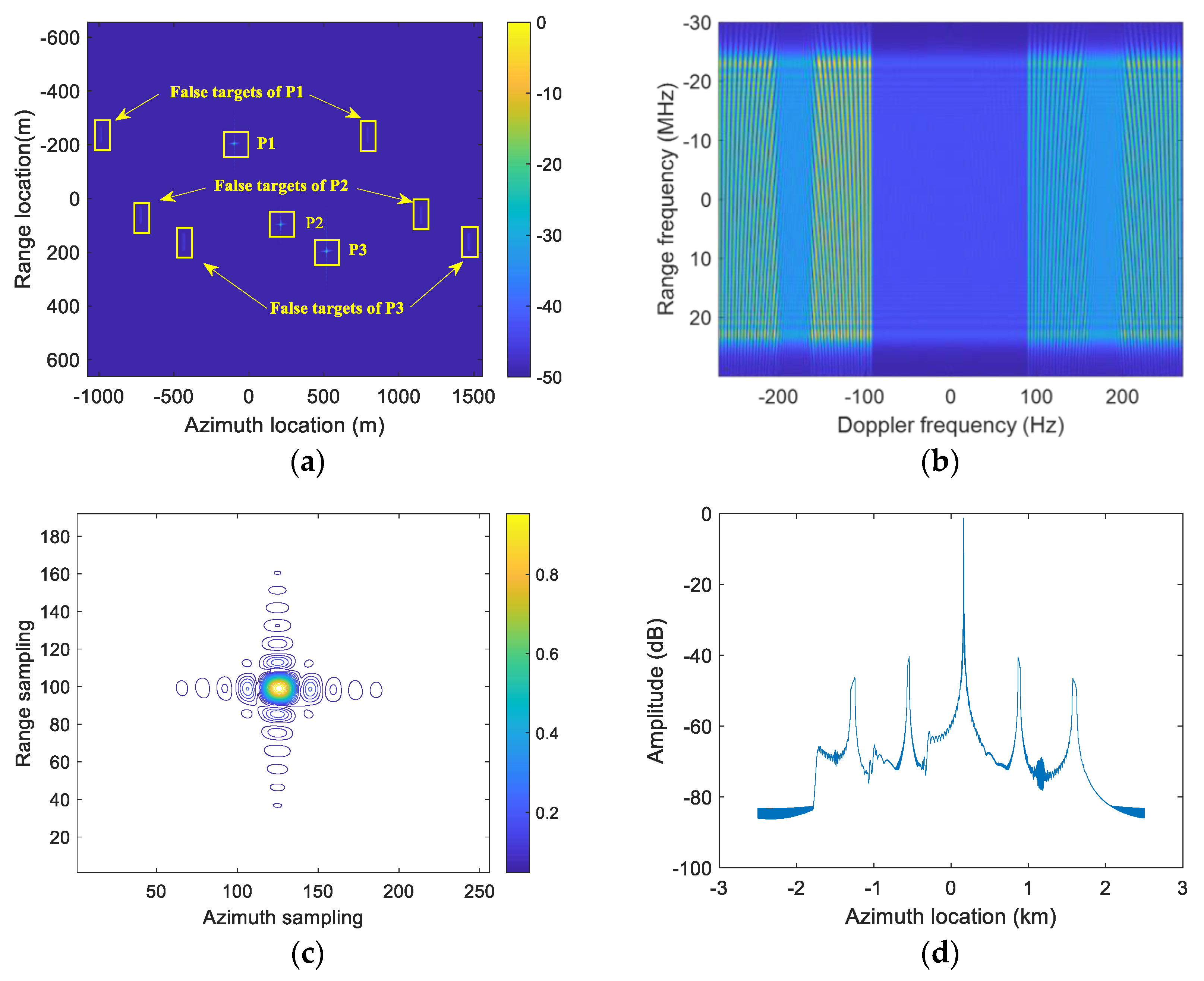
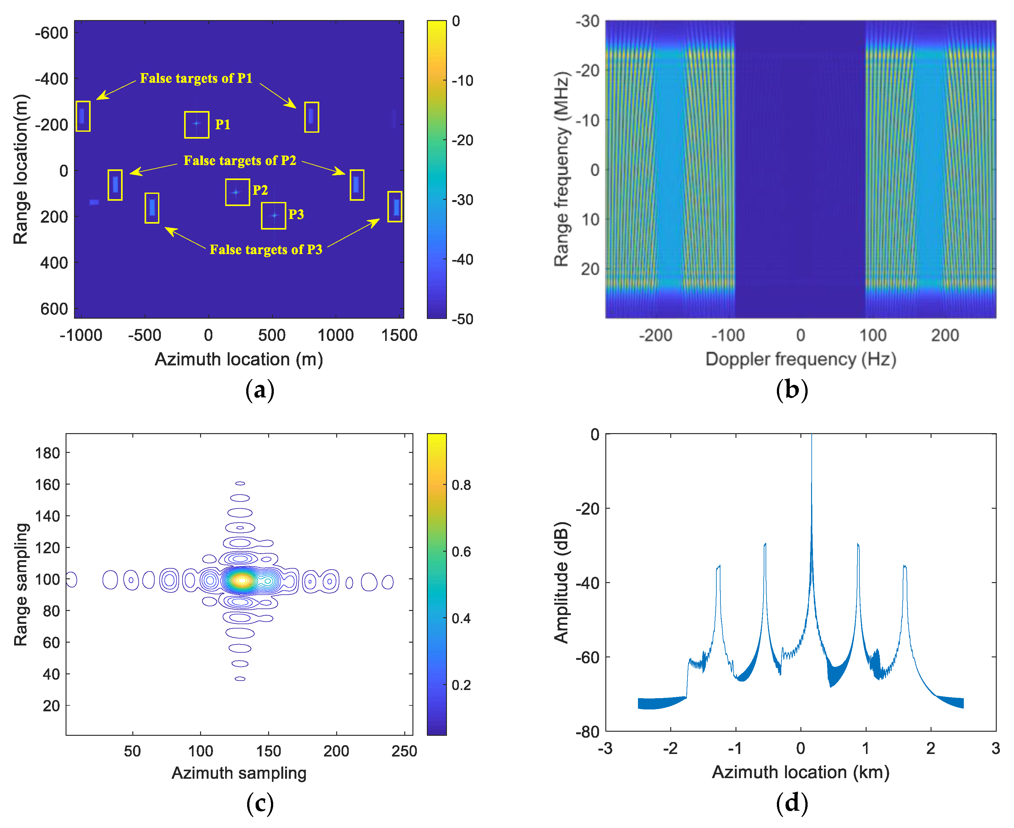
4. Simulation Experiment

To verify the correctness of the previous signal analysis and the effectiveness of the proposed multichannel reconstruction method, this section conducts three simulation experiments on multiple-point moving targets. Figure 10 shows that the slant range velocities of the three-point targets are all 5 m/s. Figure 11 shows the slant range acceleration of 1 m/s2, 3 m/s2, and 5 m/s2 added to P1, P2, and P3 points in Figure 10, respectively. After the conventional multichannel reconstruction, a point is selected here; take the point target P2 as an example. Figure 10 and Figure 11 compare the two-dimensional spectrum, point target focusing result, and the azimuth maximum profile. It can be distinctly seen that the acceleration makes the moving target produce a serious false target. Figure 12 shows the imaging results using the method proposed in this paper. Compared with the imaging results in Figure 11, the method in this paper substantially improves the imaging effect of accelerating moving targets, and false targets are well suppressed. Meanwhile, to further analyze the impact of the improved multichannel reconstruction algorithm on the imaging quality of the point targets the values for resolution (Res), peak-side-lobe ratio (PSLR), integrated-side-lobe ratio (ISLR), and maximum false target amplitude (MFTA) of each point target are summarized in Table 2.
In addition, for the completeness of the paper, a simulation experiment with three-point targets in the same scene was designed; the corresponding geometric relationship of three-point targets is illustrated in Figure 13. All point targets have different movement velocities. This provides additional evidence to support the feasibility of the proposed method. Target P1 has an along-track velocity of 10 m/s and an along-track acceleration of 5 m/s2 (Figure 13). Target P2 has an along-track velocity of 10 m/s and a slant range velocity of 10 m/s. Target P3 has a slant range velocity of 10 m/s and a slant range acceleration of 5 m/s2. When the conventional azimuth multichannel reconstruction method is used, as seen in Figure 14a, there is no change at point P1, indicating that along-track acceleration has no effect on imaging. The point target P3 is significantly out of focus and contains obvious false targets. After using the proposed azimuth multichannel reconstruction method the three-point targets can be effectively focused and false targets are obviously suppressed, as observed in Figure 14b.

5. Conclusions

Acceleration is an important feature of relative motion between a radar and its target. It can enhance maneuvering, target tracking, and target recognition capabilities, and has important application prospects in search and large-scale road monitoring. However, because of the difference in echo signal models between stationary targets and accelerated moving targets, conventional azimuth multichannel reconstruction algorithms cannot complete high-quality moving target imaging. The slant range acceleration of the moving target induces additional phase error, which leads to the phase imbalance of each channel and makes the target appear as a serious pair of false targets, which will seriously affect the SAR image interpretation. To solve this problem, an azimuth multichannel imaging method for accelerated moving targets is proposed. The key to this method is to reconstruct the Doppler spectrum of the acceleration target by using the improved azimuth multichannel reconstruction filter bank according to the echo signal model of the acceleration moving target. Since it is necessary to accurately know the velocity of the moving target before multichannel reconstruction, a velocity estimation method that combines STFT and FRFT is introduced, this method first estimates parameters roughly by STFT and then uses the FRFT method to calculate parameters accurately. Simulation results for point targets demonstrate the feasibility of introducing an azimuth multichannel reconstruction method for accelerated moving targets. In the future, research can be conducted on imaging methods of accelerating moving targets in squint mode.

Author Contributions

Conceptualization, W.X.; methodology, W.X.; software, W.X. and Y.C.; validation, W.X. and P.H.; formal analysis, Y.C.; investigation, W.X. and Y.C.; resources, W.X. and W.T.; data curation, Y.C.; writing—original draft preparation, W.X. and Y.C.; writing—review and editing, W.X. and P.H.; visualization, P.H.; supervision, W.T. and Y.Q.; project administration, W.T. and P.H.; funding acquisition, P.H. and W.X. All authors have read and agreed to the published version of the manuscript.

Funding

This research was funded by the National Natural Science Foundation of China under grant numbers 62071258, U22A2010, and 61971246.

Institutional Review Board Statement

Not applicable.

Informed Consent Statement

Not applicable.

Data Availability Statement

Data are contained within the article.

Conflicts of Interest

The authors declare no conflict of interest.

Appendix A

When processing echo signals and the multichannel reconstruction processing algorithm only needs to take into account t 2 [27], Equation (9) is then written as:
s mov , n ( t ) exp j 4 π λ R 0 exp j π λ Δ x n 2 R 0 exp j 2 π λ 2 u y R 0 v s u x Δ x n R 0 t exp j 2 π λ 2 u y 2 + 2 v s u x 2 + 2 a y R 0 + a x Δ x n 2 R 0 t 2
In order to obtain the time delay Δ t n and phase error Δ φ n of echo signal s mov , n ( t ) , the following Equation is used:
s m o v , n t = s m o v t Δ t n exp j Δ φ n
Therefore, Equation (A1) can be written as:
s mov , n ( t ) exp j 4 π λ R 0 exp j π λ Δ x n 2 R 0 exp j 2 π λ v s u x Δ x n 2 u y R 0 R 0 t exp j 2 π λ 2 u y 2 + 2 v s u x 2 + 2 a y R 0 + a x Δ x n 2 R 0 t 2 exp j 2 π λ ( v s u x ) Δ x n 2 u y R 0 2 2 R 0 2 u y 2 + 2 ( v s u x ) 2 + 2 a y R 0 + a x Δ x n exp j π λ ( v s u x ) Δ x n 2 u y R 0 2 R 0 2 u y 2 + 2 ( v s u x ) 2 + 2 a y R 0 + a x Δ x n
due to
2 u y 2 + 2 ( v s u x ) 2 + 2 a y R 0 + a x Δ x n 2 R 0 t 2 ( v s u x ) Δ x n 2 u y R 0 R 0 t + ( v s u x ) Δ x n 2 u y R 0 2 2 R 0 2 u y 2 + 2 ( v s u x ) 2 + 2 a y R 0 + a x Δ x n = 2 u y 2 + 2 ( v s u x ) 2 + 2 a y R 0 + a x Δ x n 2 R 0 t ( v s u x ) Δ x n 2 u y R 0 2 u y 2 + 2 ( v s u x ) 2 + 2 a y R 0 + a x Δ x n 2
After sorting out Equation (A3), that can be re-expressed as Equation (13):
s mov , n ( t ) exp j 4 π λ R 0 exp j π λ Δ x n 2 R 0 exp j 2 π λ 2 u y 2 + 2 ( v s u x ) 2 + 2 a y R 0 + a x Δ x n 2 R 0 t ( v s u x ) Δ x n 2 u y R 0 2 u y 2 + 2 ( v s u x ) 2 + 2 a y R 0 + a x Δ x n 2 exp j π λ ( v s u x ) 2 Δ x n 2 4 u y ( v s u x ) R 0 Δ x n + 4 u y 2 R 0 2 R 0 2 u y 2 + 2 ( v s u x ) 2 + 2 a y R 0 + a x Δ x n

References

  1. Pan, X.; Zhang, H.; Shu, G. Robust Phase Bias Estimation Method for Azimuth Multi-Channel HRWS SAR System Based on Maximum Modified Kurtosis. Electronics 2022, 11, 3821. [Google Scholar] [CrossRef]
  2. Yang, Y.; Zhang, F.; Tian, Y. High-Resolution and Wide-Swath 3D Imaging for Urban Areas Based on Distributed Spaceborne SAR. Remote Sens. 2023, 15, 3938. [Google Scholar] [CrossRef]
  3. Li, N.; Shen, Q.; Wang, L.; Wang, Q.; Guo, Z.; Zhao, J. Optimal Time Selection for ISAR Imaging of Ship Targets Based on Time-Frequency Analysis of Multiple Scatterers. IEEE Geosci. Remote Sens. Lett. 2022, 19, 1–5. [Google Scholar] [CrossRef]
  4. Wang, R.; Loffeld, O.; Neo, Y.; Nies, H.; Walterscheid, I.; Espeter, T.; Klare, J.; Ender, J. Focusing Bistatic SAR Data in Air borne/Stationary Configuration. IEEE Trans. Geosci. Remote Sens. 2010, 48, 452–465. [Google Scholar] [CrossRef]
  5. Wang, X.; Wang, R.; Li, N.; Fan, H.; Wang, Y. A method of estimating the velocity of moving targets for use in high-resolution wide-swath SAR imaging. Remote Sens. Lett. 2018, 9, 305–313. [Google Scholar] [CrossRef]
  6. Cerutti-Maori, D.; Sikaneta, I.; Klare, J. MIMO SAR Processing for Multichannel High-Resolution Wide-Swath Radars. IEEE Trans. Geosci. Remote Sens. 2014, 52, 5034–5055. [Google Scholar] [CrossRef]
  7. Zou, Q.; Xin, Q.; Cheng, P. Non-uniformly sampled signal reconstruction of DPC-MAB FMCW SAR based on fractional fourier transform. In Proceedings of the IEEE International Geoscience and Remote Sensing Symposium, Milan, Italy, 26–31 July 2015. [Google Scholar]
  8. Gebert, N. Multi-Channel Azimuth Processing for High-Resolution Wide-Swath SAR Imaging. Ph. D. Thesis, DLR-Forschungsbericht, University of Karlsruhe (TH), Wessling, Germany, June 2009. [Google Scholar]
  9. Xu, W.; Huang, P.; Wang, R.; Deng, Y. Processing of multichannel sliding spotlight and TOPS synthetic aperture radar data. IEEE Trans. Geosci. Remote Sens. 2013, 51, 4417–4429. [Google Scholar] [CrossRef]
  10. Chen, Q.; Deng, Y.K.; Liu, Y.D.; Shang, X.Q. SAR azimuth signal reconstruction based on adaptive filtering for the DPC-MAB SAR system. J. Electron. Inf. Technol. 2012, 34, 1331–1336. [Google Scholar] [CrossRef]
  11. Luo, X.; Wang, R.; Xu, W. Modification of multichannel reconstruction algorithm on the SAR with linear variation of PRI. IEEE J. Sel. Top. Appl. Earth Obs. Remote Sens. 2014, 7, 3050–3059. [Google Scholar] [CrossRef]
  12. Papoulis, A. Generalized sampling expansion. IEEE Trans. Circuits Syst. 1977, 24, 652–654. [Google Scholar] [CrossRef]
  13. Krieger, G.; Gebert, N.; Moreira, A. Unambiguous SAR signal reconstruction from nonuniform displaced phase center sampling. IEEE Geosci. Remote Sens. Lett. 2004, 1, 260–264. [Google Scholar] [CrossRef]
  14. Guo, Z.; Yuan, X.; Zhang, P. An algorithm of multichannel SAR high-resolution and wide-swath imaging. J. Electron. Inf. Technol. 2008, 30, 310–313. [Google Scholar] [CrossRef]
  15. Baumgartner, S.V.; Krieger, G. Simultaneous high-resolution wide-swath SAR imaging and ground moving target indication: Processing approaches and system concepts. IEEE J. Sel. Top. Appl. Earth Obs. Remote Sens. 2015, 8, 5015–5029. [Google Scholar] [CrossRef]
  16. Long, Y.; Zhao, F.; Zheng, M. An unambiguous imaging method of moving target for maritime scenes with spaceborne high-resolution and wide-swath SAR. IEEE Trans. Geosci. Remote Sens. 2022, 60, 1–19. [Google Scholar] [CrossRef]
  17. Jao, J.K.; Yegulalp, A. Multichannel synthetic aperture radar signatures and imaging of a moving target. Inverse Probl. 2013, 29, 054009. [Google Scholar] [CrossRef]
  18. Li, B.; Sun, G.C.; Xing, M. Moving target radial velocity estimation method for HRWS SAR system based on subspace projection. IEEE Geosci. Remote Sens. Lett. 2021, 19, 1–5. [Google Scholar] [CrossRef]
  19. Wang, X.; Zhang, R.; Wang, Z.; Zhou, Y. A Radial Velocity Estimation Method of Moving Target for Azimuth Multichannel HRWS SAR. In Proceedings of the IGARSS 2022-2022 IEEE International Geoscience and Remote Sensing Symposium, Kuala Lumpur, Malaysia, 17–22 July 2022. [Google Scholar]
  20. Hui, Z.; Fengjun, Z.; Jian, Y. SAR accelerating moving target parameter estimation and imaging based on three-order polynomial Fourier transform. J. Electron. Inf. Technol. 2016, 38, 919–926. [Google Scholar]
  21. Baumgartner, S.; Gabele, M.; Krieger, G.; Bethke, K.H.; Zuev, S. Traffic monitoring with SAR: Implications of target acceleration. In Proceedings of the EUSAR 2006; European Conference on Synthetic Aperture Radar, Dresden, Germany, 16–18 May 2006. [Google Scholar]
  22. Wei-Kong, Q.I.; Wei-Dong, Y.U.; Ping-Ping, H. Moving target acceleration indicaion and estimation for space-borne bistatic synthetic aperture radar. Syst. Eng. Electron. 2010, 32, 946–950. [Google Scholar]
  23. Yang, J.; Qiu, X.; Shang, M. A method of marine moving targets detection in multi-channel ScanSAR system. Remote Sens. 2020, 12, 3792. [Google Scholar] [CrossRef]
  24. Sharma, J. The influence of target acceleration on dual-channel SAR-GMTI (synthetic aperture radar ground moving target indication) data. Ph.D. Thesis, University of Calgary, Calgary, AB, Canada, 2005. [Google Scholar]
  25. Pan, X.; Wang, W.; Wu, L. Improved Moving Target Imaging Method for a Multichannel HRWS SAR System. IEEE Geosci. Remote Sens. Lett. 2023, 20, 1–5. [Google Scholar] [CrossRef]
  26. Kim, S.W.; Won, J.S. Acceleration compensation for estimation of along-track velocity of ground moving target from single-channel SAR SLC data. Remote Sens. 2020, 12, 1609. [Google Scholar] [CrossRef]
  27. Gebert, N.; Krieger, G.; Moreira, A. Multichannel azimuth processing in ScanSAR and TOPS mode operation. IEEE Trans. Geosci. Remote Sens. 2010, 48, 2994–3008. [Google Scholar] [CrossRef]
  28. Barbarossa, S.; Farina, A. Detection and imaging of moving objects with synthetic aperture radar. Part 2: Joint time-frequency analysis by Wigner-Ville distribution. IEE Proc. F—Radar Signal Process. 1992, 139, 79–88. [Google Scholar] [CrossRef]
  29. Fienup, J.R. Detecting moving targets in SAR imagery by focusing. IEEE Trans. Aerosp. Electron. Syst. 2001, 37, 794–809. [Google Scholar] [CrossRef]
  30. Wang, H.; Jiang, Y. Real-time parameter estimation for SAR moving target based on WVD slice and FrFT. Electron. Lett. 2018, 54, 47–49. [Google Scholar] [CrossRef]
  31. Bai, J.L.; Wu, R.G.; Wang, J.L.; Hong, Y.B. Parameter Estimation of Spaceborne SAR Based on the Combination of STFT and FRFT. Appl. Mech. Mater. 2010, 20, 954–957. [Google Scholar] [CrossRef]
Figure 1. Imaging geometric model of spaceborne SAR accelerated moving target in azimuth multichannel.
Electronics 12 04954 g001
Figure 2. Analysis of the impact of acceleration on moving target parameters. (a) Doppler second-order frequency modulation; (b) Doppler third-order frequency modulation.
Electronics 12 04954 g002
Figure 3. Analysis of the impact of velocity on the parameters of an accelerated moving target. (a) Doppler second-order frequency modulation; (b) Doppler third-order frequency modulation.
Electronics 12 04954 g003
Figure 4. Imaging results for a point target moving along track with a velocity of 10 m/s and an acceleration of 5 m/s2. (a) Contour plots of the point target. (b) Peak profile of azimuth.
Electronics 12 04954 g004
Figure 5. Imaging results for a point target moving at a slant range velocity of 10 m/s and an acceleration of 5 m/s2 (a) Contour plots of the point target. (b) Peak profile of azimuth.
Electronics 12 04954 g005
Figure 6. Analysis of the effect of acceleration on time delay and phase error. (a) Time delay; (b) phase error.
Electronics 12 04954 g006
Figure 7. Multichannel reconstruction algorithm flowchart.
Electronics 12 04954 g007
Figure 8. Acceleration estimation error under different conditions. (a) Fixed PRF value and different SCNR; (b) same SCNR and PRF value.
Electronics 12 04954 g008
Figure 9. Flow chart of moving target speed estimation method.
Electronics 12 04954 g009
Figure 10. Point target imaging results with slant range velocity. (a) Point target focusing results; (b) two-dimensional spectrum; (c) contour of P2; (d) peak profile of azimuth.
Electronics 12 04954 g010
Figure 11. Point target imaging results with slant range velocity and acceleration. (a) Point target focusing results; (b) two-dimensional spectrum; (c) contour of P2; (d) peak profile of azimuth.
Electronics 12 04954 g011
Figure 12. Imaging with improved methods. (a) Point target focusing results; (b) two-dimensional spectrum; (c) contour of P2; (d) peak profile of azimuth.
Electronics 12 04954 g012
Figure 13. Design for a scene location diagram for three-point targets.
Electronics 12 04954 g013
Figure 14. Imaging results of three-point targets. (a) Conventional azimuth multichannel imaging. (b) Proposed azimuth multichannel reconstruction. (c) Contour of P1. (d) Contour of P2. (e) Contour of P3.
Electronics 12 04954 g014
Table 1. System simulation parameters.
ParameterValue
Satellite velocity7200 m/s
Carrier frequency5.6 GHz
Number of sub-apertures3
Transmitting antenna length4 m
Receiving antenna length3 m × 3
Scene center slant distance600 km
Operated system PRF1800 Hz
Transmitted pulse width4 μs
Pulse bandwidth100 MHz
Sampling frequency120 MHz
Table 2. Imaging quality indicators of three-point targets.
MethodTargetRes. (m)Range
PSLR (dB)
ISLR (dB)MFTA (dB)
ConventionalP12.66−13.25−9.96−28.41
P22.67−13.34−10.06−25.04
P32.70−13.46−10.13−29.81
ProposedP12.67−13.29−10.07−56.68
P22.68−13.32−10.14−59.39
P32.69−13.48−10.15−60.63
Disclaimer/Publisher’s Note: The statements, opinions and data contained in all publications are solely those of the individual author(s) and contributor(s) and not of MDPI and/or the editor(s). MDPI and/or the editor(s) disclaim responsibility for any injury to people or property resulting from any ideas, methods, instructions or products referred to in the content.

