Article

UHF Textronic RFID Transponder with Bead-Shaped Microelectronic Module

Department of Electronic and Telecommunications Systems, Rzeszów University of Technology, ul. Wincentego Pola 2, 35-959 Rzeszów, Poland
*
Authors to whom correspondence should be addressed.
Electronics 2023, 12(23), 4873; https://doi.org/10.3390/electronics12234873
Submission received: 3 November 2023 / Revised: 27 November 2023 / Accepted: 30 November 2023 / Published: 3 December 2023
(This article belongs to the Special Issue Advances in Passive RFID: From UHF to THz)

Abstract

:
The idea of novel antennas and matching circuits, developed for radio frequency identification (RFID) passive transponders, and made on textile substrates, is presented in this paper. By manufacturing an RFID transponder by the means used in every clothing factory, we developed the concept of RFIDtex tags, which, as textronic devices, make a new significant contribution to the Internet of Textile Things (IoTT). The main feature of the device consists of the use of an uncommon inductively coupled system as the antenna feed element. The antenna is sewn/embroidered with a conductive thread, and the microelectronic module with an RFID chip is made in the form of a bead, using standard electronic technology. Finally, the construction of the RFIDtex tag is developed for easy implementation in production lines in the garment industry. The proposed inductive coupling scheme has not been considered anywhere, so far. The developed transponder is dedicated to operating in RFID systems of the ultra-high frequency band (UHF). The numerical calculations confirmed by the experimental results clearly indicate that the proposed coupling system between the antenna and the microelectronic module works properly and the RFIDtex device can operate correctly within a distance of several meters. The proposed design is based on the authors’ patent on the textronic RFID transponder (patent no PL 231291 B1).

1. Introduction

1.1. Issue of RFID Tags in Garment Industry

Radiofrequency identification (RFID) technology is commonly known since it is widely used in various fields of industry and everyday life [1]. The demand for such identification systems is also visible in the processes performed on a wide range of textile products, e.g., in the food service, hotel or hospital industries, professional uniforms but also more and more often in relation to clothes for general use [2]. Due to price requirements, the RFID tags have to be cheap, flexible, easy to fabricate as well as easy to assemble on products intended for identification. These demands are met by the textile electronic transponders proposed by the authors in [3], called RFIDtex transponders (or RFIDtex tags). RFIDtex tags have been designed for easy implementation on production lines used in the garment industry. Since, during its construction, the electronic device (RFID transponder) is produced on a textile substrate (directly on clothing), the RFIDtex tags should be treated as e-textiles (called textronics) [4]. Textronics are thought to be the key elements of the Internet of Textile Things (IoTT).
Some of the studies reported in the subject’s literature concern research on flexible UHF (Ultra High Frequency) RFID transponders that are intended for application on wearable or washable textile products [5,6,7]. In this subject matter’s literature, we can find various designs of RFID tags, shapes of antennas [8], technologies for fabricating elastic coils [9,10], studies on the impact of used materials [11] and some consideration of sewn or embroidered antennas [12,13]. There is little research on connecting RFID chips (that are often available as the bare semiconductor integrated circuit IC) to a conductive thread or other flexible conductors [14,15,16]. Usually, the ICs are soldered or glued, which is a challenge for unskilled workers who are not familiar with electronic technology. Thus, this electronic technology cannot be used directly on the production lines of the clothing industry. To cope with this, a microelectronic module in the form of an interposer and a two-loop inductive coupled system can be applied [3,17]. It has also been found that inductive coupling between the antenna and the radiofrequency (RF) front-end of the RFID chip is one of the methods for improving the read range when interferences with the surrounding materials occur. Since the construction shows a low sensitivity to environmental impacts, it can be used in passive UHF RFID tags dedicated to operating in challenging applications (e.g., in close proximity of metals or liquids) [18].

1.2. Design of RFIDtex Transponder-Advancements

A typical UHF RFID transponder operating in the frequency band of 860–960 MHz consists of three main components that have to be considered during designing new constructions: RFID chip, antenna and matching elements (Figure 1a).
The antenna can be produced in a multitude of shapes, as a dipole, monopole, inverted-F, microstrip patch, etc. [18]; in addition, the matching circuit can have various forms depending on the antenna design. In most cases, the chip is galvanically connected to the terminals of the matching circuit. Although there are various methods for connecting integrated circuits to PCB boards, the technological process of making such connections may become particularly challenging when dealing with small pin raster or non-PCB-based antennas. Modern chips, even when enclosed in a package, are of a relatively small size (Figure 1b). As the transponder’s planar dimensions are defined by the size of the antenna, the usage of the tiny chip aims to achieve the flattest possible RFID labels. Consequently, the chips within the labels are hardly noticeable, and thus, their connection with the antenna is difficult to locate and intentionally damage. However, the issue remains of how to reliably attach the chip to the conductive paths of the radiator. Soldering, which is commonly used in electronic technology, exhibits enormous problems in the case of flexible substrates due to the small size of the pads in the integrated circuit, as well as the mismatch of the thermal properties of the artificial materials to the high temperature of the soldering process. Therefore, various types of adhesives are most commonly used [19,20]. Galvanic connections obtained in this way are unreliable, especially in garment products that, throughout their entire life cycle, are subjected to the destructive processes of washing, ironing and use.
On the other hand, while reducing the antenna size is feasible, it negatively affects the radio communication process and the read range of the transponders. It is therefore advisable to design the antenna without downsizing it, unless necessary. From the perspective of clothing labelling, the optimal solution seems to be creating the antenna during the sewing process using conducting threads. In this way, the complete integration of the electronic system with the tagged object can be obtained. Unfortunately, the thickness of a typical conducting thread (Figure 1c) is significantly larger than the dimensions of the pads in common RFID chips (Figure 1b). It is impossible to create a reliable galvanic connection between these two components. This issue is typically resolved by creating a microelectronic circuit that has metallized holes intended for weaving the ends of the thread forming the antenna radiator (Figure 1d). Such a solution can be successfully applied in the case of HF circuits. In the UHF band, it leads to a significant change in the antenna impedance. Furthermore, the connection with braided thread exhibits significant impedance fluctuations during its use. As a result, changes in the antenna impedance cannot be predicted at the design stage of the RFIDtex tag. The lack of impedance matching between the chip and the antenna definitively hinders the operation of such a system.

1.3. Design of RFIDtex Transponder Coupling System

In order to eliminate the problems mentioned in Section 1.2, the inductive coupling system between the antenna and the RFID chip is used in the RFIDtex devices. In consequence, two main parts can be distinguished in the RFIDtex tag: the microelectronic module that is composed of the RFID chip and its inductive coupling circuit; and the antenna module also consisting of the inductive coupling circuit and the radiator of the electromagnetic waves (Figure 2). The coupling coefficient achieved by placing the inductive loops parallelly in close proximity to each other provides the possibility to transfer power and data from the antenna to the RFID chip. The microelectronic module can be produced as a semi-product in the electronic industry and then can be attached to the sewn or embroidered antenna module by the means used in the production lines of garment factories. The attachment process can be performed using conventional polyester thread or adhesive materials.
When elaborating on the concept outlined in the patent PAT.231291 [3], the authors observed that the microelectronic module can be enclosed in a button, slider or other elements known in tailoring. Depending on the purposes of the developed tags, a lot of different constructions can be proposed with regard to the requirements of the end users. In this paper, a new approach to designing the internal structure of the RFIDtex tag in relation to the previous studies is considered (Figure 3).
In the primary solution, the coupling system (shown in Figure 3a) can be easily modelled in numerical calculations [3]. This is due to the fact that the coupling circuit of the antenna and the coupling circuit of the chip have simple round forms and they do not intertwine in space. They are just arranged parallel to each other in two planes. For example, the RFIDtex construction designed with the EMCoS Studio 2021 software is presented in Figure 4. Such a model was extensively tested in the preliminary stage and the obtained results are detailed and presented in the authors’ publications [3,21].
The question is whether it is possible to simplify the process of manufacturing the RFIDtex tag in a way that could be easily implemented in clothing production lines. Thus, the design of the microelectronic module enclosed in the bead is studied in this paper. In the construction of the bead-shaped RFIDtex tag, the antenna module is embroidered or sewn with conductive threads and its coupling circuit is wrapped around the second coupling circuit in the bead (around the microelectronic module). Unfortunately, in this case, the inductive loops are arranged perpendicular to each other (Figure 3b), which significantly reduces the coupling coefficient. However, while the mutual inductance in the coupling system composed of parallel loops is easy to calculate as a standard problem of electrical engineering, the model of coupled coils with an angle included between them is much more complicated [22,23]. Generally, if the angle deviation changes from 0° to 90°, the mutual inductance gradually decreases. It can be observed that the system efficiency decreases as well—no signal passes when the two coils are perpendicular.
If the experiment is successful, we could obtain a device that could serve both as a decorative element of a textile product or an electronic memory store of the unique identification number (UID) and information of the product.

1.4. Impact of Material Parameters on RFIDtex Tag Efficiency

There are some publications that have discussed the impact of the dielectric parameters of substrates on the operational effectiveness of transponders in RFID systems [11]. For example, the antenna model designed in [17] is fabricated from various materials, and thus, an obvious effect of changing the read range is obtained depending on the dielectric parameters of the substrates. This is a direct result of the change in the impedance matching, while the impedance is expressed by complex numbers [3]. Changing the dielectric parameters of the substrate causes a change in the antenna impedance ZTA and thus affects the mismatch with the chip input impedance ZTC (Figure 4c). The ZTA parameter is considered from the perspective of the chip terminals, and as such, it includes the impedance of both the coupling circuits and the radiator. If the impedances are not coupled, ZTA = ZTC* [21], the signal is reflected and only part of the energy reaches the chip’s input circuit. However, it should be clearly stated that the antenna should be designed specifically for the substrate on which it is fabricated. The dielectric properties of the used materials have to be taken into consideration in the calculations. Thus, a properly developed transponder always operates efficiently in an RFID system when the electromagnetic field is not disturbed by the surrounding objects.
On the other hand, metal objects or liquids in close proximity have a similar effect on the antenna impedance. In this case, the human body also negatively influences this parameter. Contrary to appearances, such detuning in the radio circuit may prove to be a significant advantage when designing utility applications.
In automated identification systems dedicated to the stages of production, storage, distribution or disposal, it is necessary to ensure that no objects disturb the electromagnetic field and affect the operation of the transponders during product identification. Of course, at the engineering level, such requirements for the applications should not pose any significant problems. It remains to be studied the suitability of the RFIDtex tags for the everyday use of textile products. Let us consider one such application, e.g., the washing process. The automatic selection of the washing machine settings can be based on the data read from the chip’s memory. This process should occur when inserting the marked products into the drum. Likewise, the interrogation of the transponders can also take place after inserting them into the drum. The effectiveness of the tag recognition can be ensured by appropriately shaping the interrogation zone [1] inside the metal drum. Additionally, the probability of identification can be increased by making several reading revolutions of the laundry. In any case, it is possible to obtain an almost 100% certainty of the identification. Of course, the drum has to be properly constructed, and the interrogation zone has to cover its entire interior.
It would actually be possible to explore the various implementations of the RFIDtex systems in a similar way. Although the influence of environmental objects on the antenna operation is evident, it should not have any significance in some specific applications. The question remains of whether the RFIDtex tag can be reliably read when it is close to the human body. In this case, the read range will definitely drop. Thus, the key consideration is whether this behaviour is a disadvantage or an advantage of the system. In times of concern for the security of personal data, the reduction in or absence of identification should be regarded as an important advantage. At many conferences where the RFIDtex solution was presented, there were always voices expressing objections that users may not want a third party to have access to the information stored in the tags on their clothes. However, on the other hand, many people would like, without any reservations, to boast about the stores at which they shop. The protection of personal data is an extremely important problem in this case, and requires systemic solutions, but of a completely different type, not related to the subject matter of the presented research.

2. Materials and Methods

The coupling system is the most important component of the RFIDtex transponder. It determines the identification efficiency in the entire RFID system. It is also the most difficult element to model in numerical calculations, especially when the threaded bead is taken into consideration. The problem is presented and studied by the authors on the numerical model elaborated in the EMCoS Studio 2021 software (Figure 5).
A model of the chip’s coupling circuit can be designed relatively easily (Figure 5a). Following the research strategy, this circuit can be configured as either a one-turn or two-turn coil, with outer diameters of 5.2 mm or 5.7 mm.
The essential part of the model of the bead-shaped RFIDtex tag is the conductive thread wrapped around the microelectronic module (Figure 5b,c). This element is the most difficult for modelling. In the design software being employed, there are no built-in tools designated for directly creating this type of spatial structures. The natural shape of sewing with the conductive thread around the microelectronic bead was reproduced by making auxiliary geometries in the form of circles using standard Arc and Polyline tools. The spatial arrangement of the antenna radiator ensures proper insulation between the conductive thread and the coupling circuit of microelectronic module.
In order to create the model of the antenna coupling circuit, two auxiliary circles with diameters of 3 mm and 6.5 mm are prepared, as depicted by the green circles in Figure 5c. The outer circuit is enlarged to 7 mm for the microelectronic module with the coupling coil diameter of 5.7 mm. Equally distributed points (highlighted in red) are positioned on the circles in such a way that the distance between subsequent loops of the antenna’s coupling circuit is 1 mm along the circle (highlighted with a dotted green line), aligning between the paths of the chip’s coupling circuit.
The antenna’s complex impedance, ZTA, is the main parameter that has to be considered in the performed investigation. It has to be matched (coupled) to the impedance of the RFID chip, ZTC (ZTA = ZTC*). The impedances of the coupling system also have to be taken into consideration in numerical calculations. The impedance parameters of the RFID chip (SL3S1214–UCODE 7 m in case SOT886; by NXP Semiconductors, Eindhoven, the Netherlands) that are used in the experiment are presented in Table 1.
To model the RFIDtex transponder, parameters of the wires used to prepare conductive loops has to be known. It is not a problem in the case of the microelectronic module which is made on a standard Kapton flexible substrate with Cu clad. But, wires of the antenna module are manufactured with the Rupalit V155 10 × 0.04 mm Litz (by Dacpol, Piaseczno, Poland) conductive thread. The input parameters of the Litz had to be measured in laboratory preliminary experiments: thickness 0.18 mm, electrical resistivity ρ = 0.08 Ω·m, conductance σ = 12 S.
The basic research strategy is to develop several versions of the wrapped construction that differ in the number of turns in both the antenna coupling circuit and the microelectronic module coupling circuit. On the basis of prepared models (Figure 5), the influence of the number of turns is examined, and, additionally, the impact of the coupling system on the RFIDtex tag operation is analysed.

3. Results—Simulations

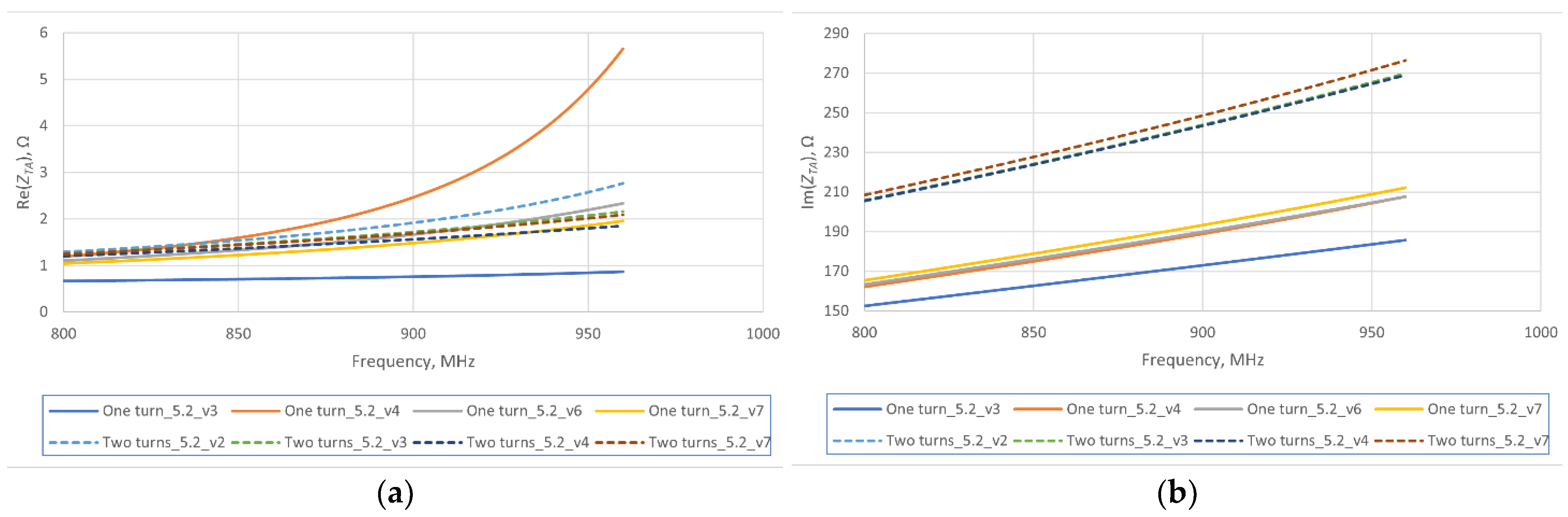
3.1. One-Turn Coil in Microelectronic Module

The first model of the RFIDtex transponder is prepared for the one-turn coupling circuit of microelectronic module (Figure 5b). The diameter of the coil is 5.2 mm. Around the coil, there are wound 3, 4, 6 or 7 windings of the coupling circuit of the antenna module (accordingly, One turn_5.2_v3, _v4, _v6, _v7 in Figure 6). The length of the antenna dipole (conductive thread) is 13 cm.
The ZTA is the main determinant for the numerical calculations. Its imaginary part oscillates in the range of <150;220> Ω, whereas the real part is a few ohms (Figure 6). Further increasing the number of winding turns does not allow us to obtain the desired value (ZTC*) (Table 1). Thus, the thread braid does not have a significant effect on changing the imaginary part. Consequently, it was necessary to consider designing a new geometry that meets the conditions of matching the impedance to the chip.

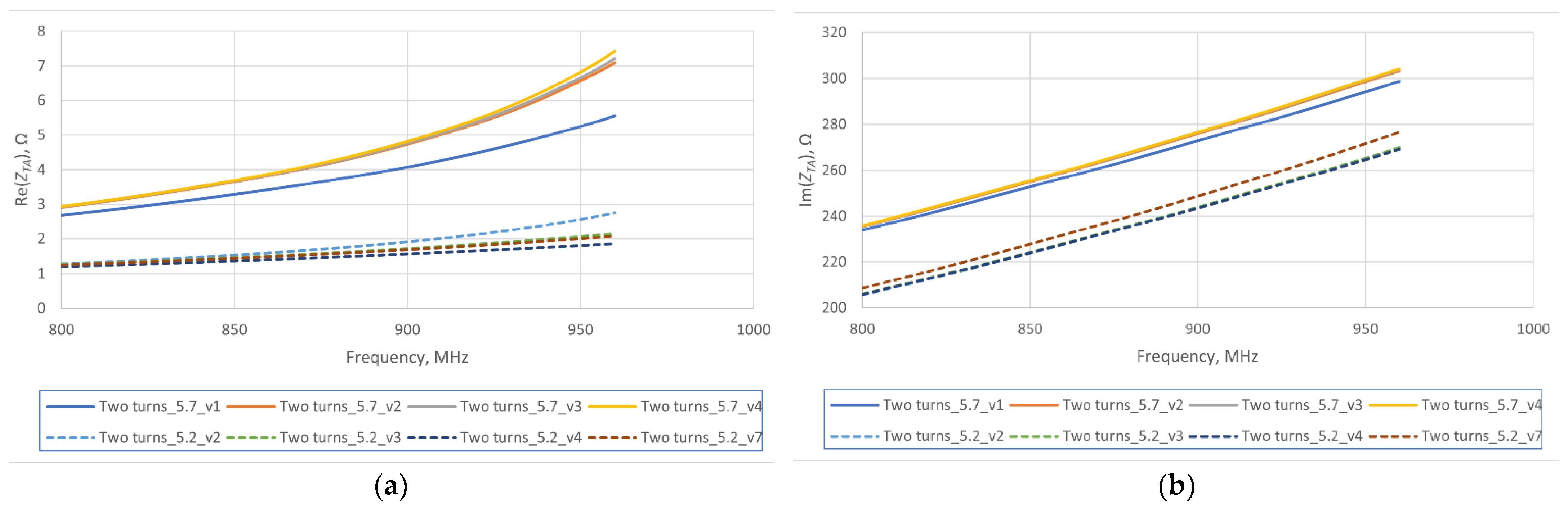
3.2. Two-Turn Coil in Microelectronic Module

By using a two-turn coupling circuit of the microelectronic module (Figure 5c), an increase in the values of Im(ZTA) ϵ <200;280> Ω is obtained. The calculations are repeated at 2, 3, 4 or 7 windings of the coupling circuit in the antenna module (accordingly, Two turns_5.2_v2, _v3, _v4, _v7 in Figure 6). The Im(ZTA) changes slightly with the number of turns in the antenna module. Also in this case, the assumed value of Re(ZTC*) (Table 1) cannot be reached. Moreover, it should be noticed that many turns in the antenna module cause a problem due to their even distribution around the microelectronic module.

3.3. Two-Turn Coil in Enlarged Microelectronic Module

A significant improvement in the impedance matching conditions can be obtained by increasing the diameter of the microelectronic module. If the diameter of its coupling circuit is enlarged to 5.7 mm, the values of the Im(ZTA) oscillate in the range of <240;350> Ω (Figure 7). This gives a significant increase compared to the previous designs. Unfortunately, the Re(ZTA) is still too small. The calculations are performed at 1, 2, 3 or 4 windings in the antenna module (accordingly, Two turns_5.7_v1, _v2, _v3, _v4 in Figure 7) and compared with the previous models.

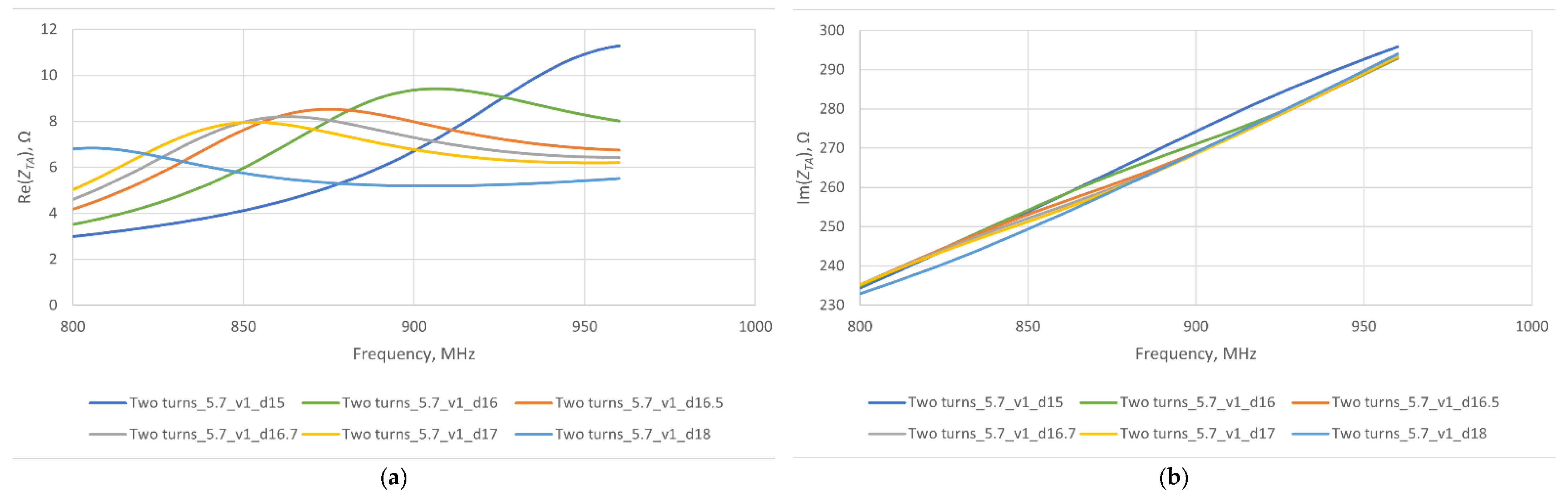
3.4. Length of Antenna Radiator

Since the additional coupling turns in the antenna module or the enlarged diameter of the microelectronic module are technologically burdensome, it is necessary to look for other parameters the change in which would create better matching conditions.
The length of the antenna radiator can be determined on the basis of a simple relation: λ / 2 = 0.5 · c / f , where λ/2 means the length of the antenna, c—the light speed in a vacuum, f—the operating frequency of the antenna. At the operating frequency of f0 = 915 MHz, the length of the antenna should be 16.4 cm, whereas it equals 17.3 cm for f0 = 866 MHz. Because the radiator is constructed using a conductive thread with a relatively high resistance, it is necessary to shorten the obtained lengths. This adjustment is required due to the propagation of electromagnetic waves in materials other than a vacuum [24]. Further, if the conductive thread of the calculated length is wrapped around the microelectronic module, the overall length of the antenna is shortened. Therefore, the question arises of whether the part of the thread used to create the coupling circuit of the antenna module should be taken into account when determining the length of the antenna.
With a change in the dipole length from 15 cm to 18 cm, there is no significant variations in the Im(ZTA) (Figure 8). However, it significantly influences the value of the Re(ZTA). For example, resonance is obtained for 16.5 cm @ 866 MHz
Regardless of the radiator length, general conclusions can be drawn for all cases. Each time the number of coupling turns in the antenna module is changed, the values of the ZTA remains almost at the same level. This confirms that the coupling system proposed for the RFIDtex transponder has no significant effect on the ZTA. However, the length of the antenna radiator has to be selected adequately to the operating frequency, taking into account the size of the coupling system.

4. Experimental Results

4.1. General Assumption of Experiments

As part of the experiment, RFIDtex demonstrators with a different number of turns (sample: H1-1 turn, H2-2 turns, H3-3 turns, H4-4 turns) in the coupling circuit of the antenna module were prepared. Denim was chosen as the substrate of the textronic device. In the manufacturing process, special attention was paid to the accurate trimming of the 8 cm radiator arms and to the even distribution of the coils of the antenna module around the microelectronic module (Figure 9a,b).

4.2. Experiment in Laboratory Stand

The measurements were performed in two stages. At the beginning, the Voyantic Tagformance Pro system (Figure 10a) installed in a MVG anechoic chamber (Figure 10b) was used to determine the theoretical read range of the RIDtex tag samples.
The RFIDtex demonstrators were tested to work in the RFID system compliant with the ETSI EN 302 208 standard [25] (PEIRPmax = 2 W EIRP, Effective Isotopically Radiated Power). The theoretical read range in the forward rPwrMax and reverse rBtrMax direction were determined on the basis of the power flow [3]:
r P w r M a x = c 4 π f P E I R P m a x P P w r ,
r B t r M a x = c 4 π f P B t r P R m i n ,
where PEIRPmax means the maximal effective isotropic radiated power (PEIRPmax = 3.28 W EIRP for ETSI EN 302 208 European standard or PEIRPmax = 4 W EIRP for FCC Part 15.247 American standard); PPwr is the minimum power emitted by the read/write device (RWD) that is needed to properly start (power up) the transponder under tests (TUT); PBtr is the effective backscatter power transmitted by the RWD at which TUT answers to the RWD command; PRmin means the sensitivity of the RWD.
The frequency resonance in the vicinity of 910 MHz (Figure 11) confirms the convergence of the numerical calculations with the measurements for the prepared samples. The coupling circuit of the antenna module with three turns has the best operating parameters in the tested band <800;1000> MHz. With each subsequent turn of the coupling coil, the operating parameters of the H1–H3 samples improve. However, the arrangement with four turns has worse characteristics. This is due to the inaccuracy in winding the turns around the microelectronic module. The coil turns have to be wound very close to each other in even intervals, which is very hard to execute in practise (manual manufacturing).

4.3. Experiment in Quasi-Real Conditions

In the second stage of the experiment, the elaborated RFIDtex demonstrators were tested in quasi-real conditions. The basic parameter—read range—was determined according to the number of thread turns (Table 2) as well as the length of the radiator (Table 3) for the best of the H samples. The construction with three turns of the coil shows the best performance in these measurements as well.
The apparatus set-up of the second experiment consists of ID ISC.LRU3000 RWD by Feig (output power PRWD = 0.3 W; sensitivity 65 dBm) with Feig ID ISC.ANT.U170/170-EU UHF antenna connected with ID ISC.ANT.C2-A UHF Antenna Cable.

5. Conclusions

This paper presents the innovative concept of a textronic RFID tag with a bead-shaped microelectronic module. Its key element is the antenna coupling circuit, made through windings around the coupling circuit in the microelectronic module. The operation of the proposed structure in the 860–960 MHz band has been confirmed on the basis of the numerical calculations as well as in the experimental measurements.
It should be emphasized, however, that the simulation toolkit of EMCoS Studio 2021 used for preparing the model and numerical calculations does not provide any procedures, guidelines or software options that could allow us to create, ad hoc, a coupling system with such an advanced shape in the proposed design of the RFIDtex tag. Thus, the preparation of the conceptual bead and the analysis of the coupling system impact on the RFIDtex tag parameters was the one of main challenges of this work.
The elaborated RFIDtex transponder with a bead-shaped microelectronic module is especially dedicated for the electronic marking of textiles with a limited surface area, such as underwear.
The conducted investigations prove that it is possible to design a model of a UHF textronic RFID transponder with the bead-shaped microelectronic module, as well as to perform effective numerical calculations leading to the creation of a properly operating device. It is also proven that such a device can effectively operate in practice within selected automatic object identification systems. Despite its low read range, the main advantage of the proposed solution lies in its ease of implementation on production lines in the textile industry. Since, in general, RFIDtex tags are dedicated to function throughout all the stages of the electronically marked product lifecycle, tests are carried out to assess the resistance of these devices to environmental conditions. It should be noticed that the product usage stage stands out as the least predictable and longest-lasting. The partial results of the environmental tests are published by the authors in the article [26]. They clearly show that RFIDtex transponders are unfortunately subjected to rapid degradation, mainly due to the unsatisfactory parameters of the conductive threads. During the subsequent washing or ironing processes, not only does the thread resistance increase, but both the threads and substrates also experience shrinking or stretching. These changes may lead to a significant deterioration in the transponder performance and, consequently, an inability to recognize garments in household appliances (e.g., washing machine). Nevertheless, it is always possible to read the information stored in the chip’s memory from a short distance with a high power at the output of the RWD. Therefore, in the final stage of the product lifecycle, it will be possible to obtain data on its material composition and the method of disposal, which is certainly a significant advantage of the proposed solution. Unfortunately, if the antenna radiator is entirely broken, the tag becomes inoperable. Therefore, selecting the appropriate conductive thread is crucial. Of the more than ten conductive threads offered by various manufacturers and tested by the authors, half of them were damaged after just a dozen or so washes. The results of these studies are currently being processed and will be published soon. Thus, it can be seen that, although the RFIDtex tag is ready to work in a wide range of applications, it is necessary to conduct research on the materials used for its production.

Author Contributions

Conceptualization, P.J.-M. and M.W.; methodology, P.J.-M.; software, K.K.; validation, P.P.; formal analysis, K.S. and K.K.; investigation, P.P., K.S. and K.K.; resources, P.P., K.S. and K.K.; data curation, P.P., K.S. and K.K.; writing—original draft preparation, P.P. and K.K.; writing—review and editing, M.W.; visualization, K.S. and M.W.; supervision, P.J.-M.; project administration, P.J.-M. and M.W.; funding acquisition, P.J.-M. All authors have read and agreed to the published version of the manuscript.

Funding

This research paper was developed under the project financed by the Minister of Education and Science of the Republic of Poland within the “Regional Initiative of Excellence” program for the years 2019–2023. Project number 027/RID/2018/19, amount granted 11 999 900 PLN.

Institutional Review Board Statement

Not applicable.

Informed Consent Statement

Not applicable.

Data Availability Statement

All calculated and measured data will be provided upon request to the correspondent authors by email with appropriate justification.

Conflicts of Interest

The authors declare no conflict of interest. The funders had no role in the design of the study; in the collection, analyses, or interpretation of the data; in the writing of the manuscript; or in the decision to publish the results.

References

  1. Finkenzeller, K. RFID Handbook—Fundamentals and Applications in Contactless Smart Cards. Radio Frequency Identification and Near-Field Communication, 3rd ed.; Wiley: Chichester, UK, 2010; ISBN 978-0-470-69506-7. [Google Scholar]
  2. Dobkin, D.M. The RF in RFID, 2nd ed.; Newnes: Oxford, UK, 2012; Volume 2nd, ISBN 0123945836. [Google Scholar]
  3. Jankowski-Mihułowicz, P.; Węglarski, M.; Chamera, M.; Pyt, P. Textronic UHF RFID Transponder. Sensors 2021, 21, 1093. [Google Scholar] [CrossRef] [PubMed]
  4. Van Langenhove, L.; Black, S.; Qin, Y.; Nierstrasz, V.A.; Pause, B.; Catrysse, M.; Pirotte, F.; Puers, R.; Van Langenhove, L.; Hertleer, C.; et al. Contributor Contact Details. In Smart Textiles for Medicine and Healthcare; Van Langenhove, L., Ed.; Woodhead Publishing Series in Textiles; Woodhead Publishing: Sawston, UK, 2007; pp. xi–xiii. ISBN 978-1-84569-027-4. [Google Scholar]
  5. Miozzi, C.; Amato, F.; Marrocco, G. Performance and Durability of Thread Antennas as Stretchable Epidermal UHF RFID Tags. IEEE J. Radio Freq. Identif. 2020, 4, 398–405. [Google Scholar] [CrossRef]
  6. Mohamadzade, B.; Hashmi, R.M.; Simorangkir, R.B.V.B.; Gharaei, R.; Ur Rehman, S.; Abbasi, Q.H. Recent Advances in Fabrication Methods for Flexible Antennas in Wearable Devices: State of the Art. Sensors 2019, 19, 2312. [Google Scholar] [CrossRef] [PubMed]
  7. Khan, Z.; Chen, X.; He, H.; Xu, J.; Wang, T.; Cheng, L.; Ukkonen, L.; Virkki, J. Glove-Integrated Passive UHF RFID Tags—Fabrication, Testing and Applications. IEEE J. Radio Freq. Identif. 2019, 3, 127–132. [Google Scholar] [CrossRef]
  8. Koski, K.; Sydanheimo, L.; Rahmat-Samii, Y.; Ukkonen, L. Fundamental Characteristics of Electro-Textiles in Wearable UHF RFID Patch Antennas for Body-Centric Sensing Systems. IEEE Trans. Antennas Propag. 2014, 62, 6454–6462. [Google Scholar] [CrossRef]
  9. Simorangkir, R.B.V.B.; Gawade, D.R.; Kumar, S.; O’Flynn, B.; Buckley, J.L.; Hannon, T.; Donovan, P.; Newberry, R. Screen printed epidermal antenna for IoT health monitoring. In Proceedings of the 2021 IEEE Asia-Pacific Microwave Conference (APMC), Brisbane, Australia, 28 November–1 December 2021; IEEE: New York, NY, USA, 2021; pp. 395–397. [Google Scholar]
  10. Jaakkola, K.; Sandberg, H.; Lahti, M.; Ermolov, V. Near-Field UHF RFID Transponder With a Screen-Printed Graphene Antenna. IEEE Trans. Compon. Packag. Manuf. Technol. 2019, 9, 616–623. [Google Scholar] [CrossRef]
  11. Casula, G.A. A design rule to reduce the human body effect on antennas for short range NF-UHF RFID systems. In Proceedings of the 2018 2nd URSI Atlantic Radio Science Meeting (AT-RASC), Gran Canaria, Spain, 28 May–1 June 2018; IEEE: New York, NY, USA, 2018; pp. 1–4. [Google Scholar]
  12. Radouchova, M.; Suchy, S.; Blecha, T. Embroidered flexible elastic textile antenna as strain sensor. In Proceedings of the 2022 45th International Spring Seminar on Electronics Technology (ISSE), Vienna, Austria, 11–15 May 2022; IEEE: New York, NY, USA, 2022; pp. 1–6. [Google Scholar]
  13. Bakkali, M.E.; Martinez-Estrada, M.; Fernandez-Garcia, R.; Gil, I.; Mrabet, O.E. Effect of bending on a textile UHF-RFID Tag Antenna. In Proceedings of the 2020 14th European Conference on Antennas and Propagation (EuCAP), Copenhagen, Denmark, 15–20 March 2020; IEEE: New York, NY, USA, 2020; pp. 1–5. [Google Scholar]
  14. Szalapak, J.; Scenev, V.; Janczak, D.; Werft, L.; Rotzler, S.; Jakubowska, M.; von Krshiwoblozki, M.; Kallmayer, C.; Schneider-Ramelow, M. Washable, Low-Temperature Cured Joints for Textile-Based Electronics. Electronics 2021, 10, 2749. [Google Scholar] [CrossRef]
  15. de Mulatier, S.; Nasreldin, M.; Delattre, R.; Ramuz, M.; Djenizian, T. Electronic Circuits Integration in Textiles for Data Processing in Wearable Technologies. Adv. Mater. Technol. 2018, 3, 1700320. [Google Scholar] [CrossRef]
  16. Simegnaw, A.A.; Malengier, B.; Rotich, G.; Tadesse, M.G.; Van Langenhove, L. Review on the Integration of Microelectronics for E-Textile. Materials 2021, 14, 5113. [Google Scholar] [CrossRef] [PubMed]
  17. Moraru, A.; Ursachi, C.; Helerea, E. A New Washable UHF RFID Tag: Design, Fabrication, and Assessment. Sensors 2020, 20, 3451. [Google Scholar] [CrossRef] [PubMed]
  18. Abdulghafor, R.; Turaev, S.; Almohamedh, H.; Alabdan, R.; Almutairi, B.; Almutairi, A.; Almotairi, S. Recent Advances in Passive UHF-RFID Tag Antenna Design for Improved Read Range in Product Packaging Applications: A Comprehensive Review. IEEE Access 2021, 9, 63611–63635. [Google Scholar] [CrossRef]
  19. Koski, K.; Koski, E.; Ukkonen, L.; Sydanheimo, L.; Bjorninen, T.; Virtanen, J.; Elsherbeni, A.Z. Effects of laboratory-scale IC attachment methods on passive UHF RFID tag performance. In Proceedings of the 2011 IEEE International Symposium on Antennas and Propagation (APSURSI), Washington, DC, USA, 3–8 July 2011; IEEE: New York, NY, USA, 2011; pp. 1004–1007. [Google Scholar]
  20. Choo, J.; Ryoo, J. Analysis of Flip Chip Bonding for Performance Stability of UHF RFID Tags. IEEE Trans. Compon. Packag. Manuf. Technol. 2014, 4, 1714–1721. [Google Scholar] [CrossRef]
  21. Jankowski-Mihułowicz, P.; Węglarski, M.; Wilczkiewicz, B.; Chamera, M.; Laskowski, G. The Influence of Textile Substrates on the Performance of Textronic RFID Transponders. Materials 2022, 15, 7060. [Google Scholar] [CrossRef] [PubMed]
  22. Li, Y.; Liu, J.; Yang, Q.; Ni, X.; Zhai, Y.; Lou, Z. Directional Characteristics of Wireless Power Transfer via Coupled Magnetic Resonance. Electronics 2020, 9, 1910. [Google Scholar] [CrossRef]
  23. Han, Y.; Wang, X. Calculation of Mutual Inductance Based on 3D Field and Circuit Coupling Analysis for WPT System. Int. J. Control. Autom. 2015, 8, 251–266. [Google Scholar] [CrossRef]
  24. Stutzman, W.L.; Gary, A. Thiele Antenna Theory and Design, 3rd ed.; Wiley: Hoboken, NJ, USA, 2012. [Google Scholar]
  25. European Telecommunications Standards Institute: ETSI EN 302 208 V3.3.1 (2020-08); Radio Frequency Identification Equipment Operating in the Band 865 MHz to 868 MHz with Power Levels up to 2 W and in the Band 915 MHz to 921 MHz with Power Levels up to 4 W; Harmonised Standard for Access to Radio Spectrum. F-06921 Sophia Antipolis Cedex: Valbonne, France, 2020.
  26. Nizioł, M.; Jankowski-Mihułowicz, P.; Węglarski, M. The Influence of the Washing Process on the Impedance of Textronic Radio Frequency Identification Transponder Antennas. Materials 2023, 16, 4639. [Google Scholar] [CrossRef] [PubMed]
Figure 1. Designing RFIDtex transponder: (a) example of typical RFID tag design; (b) example of contemporary encapsulation of RFID chip; (c) conductive Adafruit 2 ply stainless thin thread; (d) example of galvanic connection between electronic module and conductive yarn system under laboratory tests.
Electronics 12 04873 g001
Figure 2. Idea for RFIDtex transponder.
Electronics 12 04873 g002
Figure 3. RFIDtex transponder: (a) primary solution of coupling system; (b) coupling system according to new conception of threaded bead.
Electronics 12 04873 g003
Figure 4. RFIDtex transponder according to Figure 3a: (a) classical model; (b) sample under tests; (c) diagram of electrical equivalent of RFIDtex transponder.
Electronics 12 04873 g004
Figure 5. Model of coupling system in bead-shaped RFIDtex tag: (a) detailed diagram of two-loop chip’s coupling circuit; (b) model with one turn in coupling circuit of microelectronic module; (c) designing process of model with two turns in coupling circuit of microelectronic module.
Electronics 12 04873 g005
Figure 6. Antenna impedance ZTA calculations for microelectronic module with 5.2 mm diameter: (a) real part of ZTA; (b) imaginary part of ZTA.
Electronics 12 04873 g006
Figure 7. Antenna impedance ZTA calculations for microelectronic module with 5.2 mm and 5.7 mm diameter: (a) real part of ZTA; (b) imaginary part of ZTA.
Electronics 12 04873 g007
Figure 8. Antenna impedance ZTA calculations for various length of antenna dipole: (a) real part of ZTA; (b) imaginary part of ZTA.
Electronics 12 04873 g008
Figure 9. Experiment sample H1-H4: (a) example of coupling system; (b) four examples of RFIDtex transponder.
Electronics 12 04873 g009
Figure 10. Experimental stand: (a) data condition in Voyantic Tagformance Pro development tool; (b) MVG anechoic chamber.
Electronics 12 04873 g010
Figure 11. Theoretical read range: (a) in forward rPwrMax and (b) reverse rBtrMax direction.
Electronics 12 04873 g011
Table 1. Parameters of RFID chip SL3S1214–UCODE 7 m.
FrequencyImpedance of Bare ChipImpedance of Packaged Chip
866 MHz14.5-j293 Ω14.8-j264 Ω
915 MHz12.5-j277 Ω12.8-j248 Ω
953 MHz12.5-j267 Ω12.8-j238 Ω
Read sensitivity/Minimum input power −21 dBm
Table 2. Read range of RFIDtex demonstrators vs. number of turns.
Sample No.Number of TurnsRead Range, cm
H11119
H22176
H33187
H44107
Table 3. Read range of RFIDtex demonstrators vs. length of radiator (measurements on the basis of H3 sample).
Sample No.Length of RadiatorRead Range, cm
120.554
21956
318111
417124
516187
615187
714156
813107
91243
Disclaimer/Publisher’s Note: The statements, opinions and data contained in all publications are solely those of the individual author(s) and contributor(s) and not of MDPI and/or the editor(s). MDPI and/or the editor(s) disclaim responsibility for any injury to people or property resulting from any ideas, methods, instructions or products referred to in the content.

