1. Introduction
The distribution of energy in China and the trend of power reform have determined that DC transmission has become an essential direction for power grid construction [
1]. In recent years, the State Grid of China and China Southern Power Grid Corporation have successively planned and constructed multiple DC lines [
2,
3]. However, the conventional direct current (LCC-HVDC) has a higher risk of commutation failure (CF); at the same time, the flexible direct current (VSC-HVDC) also has shortcomings, such as smaller capacity and higher cost. Therefore, combining conventional LCC converters with flexible VSC converters for hybrid DC transmission has become the development direction of DC transmission in China [
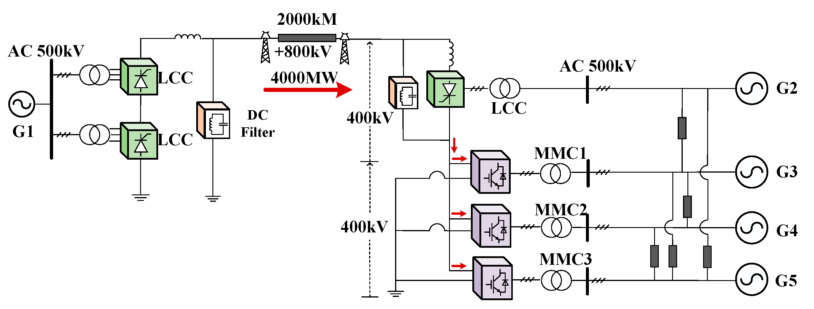
4]. The ±800 kV ultra-high voltage hybrid DC transmission project from Baihetan to Jiangsu (BTH-JS) is expected to be put into operation in 2023.
The rectifier of the BTH-JS hybrid HVDC system employs LCC. As for the inverters, they introduce innovative LCC cascaded with multiple MMCs, making the world’s first hybrid cascaded DC transmission system a real project. The ultra-high-voltage hybrid cascaded DC system fully utilizes the advantages of the MMC converter and LCC converter. On the one hand, the MMCs can stabilize the receiving end voltage of AC grids, reducing the probability of LCC CF. On the other hand, multiple MMCs are configured in parallel to increase the acceptable capacity of the system. Notably, the unique topology of LCC and MMC parallel groups enables the receiving end to have the conditions for decentralized access to the AC power grid, which can form a multi-point form that meets the electricity demand of multiple load centers. Whether in the early construction or later operation, it can significantly improve the flexibility and reliability of the system.
Recent research concerning hybrid DC transmission primarily focuses on topology structure and control methods. Reference [
5] proposes a hybrid DC topology structure using LCC for rectification measurement and a VSC inverter, which reduces system cost and power loss, as well as avoids CF, which is suitable for unidirectional power transmission. Reference [
6] proposes an electro-mechanical transient modeling and power flow calculation method for LCC-MMC, laying the foundation for subsequent research on the transient stability of multi-terminal hybrid DC transmission. Due to the LCC commutation components, it is not possible to achieve power flow reversal. Reference [
7] proposes a hybrid bipolar high-voltage DC system in which the positive electrode uses LCC and the negative electrode uses VSC. The coordinated control method decreases the risk of CF, stabilizes AC voltage, and enhances system robustness. However, VSC and LCC at the same end limit the current of LCC and cannot maximize its effectiveness. Reference [
8] proposes a doubly fed HVDC structure in that the LCC inverter is linked with the VSC rectifier on the same bus and analyzes the impact of VSC on the power control characteristics of LCC. Reference [
9] analyzes the influence of LCC on the strength of VSC systems based on the aforementioned topological structure. Reference [
10] proposes a hybrid three-terminal DC transmission system topology, where the LCC rectifier and dual MMC inverter are connected in parallel to form a more flexible and larger capacity DC transmission method, providing a theoretical basis for the application of the Wudongde DC project. Reference [
11] proposes a topology structure of LCC rectifier and LCC connected in series with MMC inverters. The different topologies and control methods of the system’s receiving end are analyzed and compared, indicating that decentralized access of the receiving MMCs can effectively isolate fault points, providing a reference for constructing the BTH-JS DC project.
As for the control methods, reference [
11] analyzes the different receiver topologies and control methods of hybrid cascaded systems, laying the foundation for the next step of research. It is also possible to adjust the power command value through the imbalance of MMC current when the receiving system malfunctions, suppressing the imbalance current and DC overcurrent between MMC and reducing the impact on flexible and direct equipment [
12]. Reference [
13] proposes a hybrid DC transmission system based on LCC-HVDC at both ends, where two down-side parallel MMCs are on the inverter side, and proposes a fault recovery strategy. However, this control strategy only focuses on DC faults and does not analyze faults either on the rectifier side or the AC system. A hybrid multi-drop DC transmission system proposes a dynamic power-adjustment strategy based on master–slave mode is investigated in [
14], which can maintain voltage stability during system faults and prevent the large-scale transfer of power at the receiving end, leading to overvoltage and overcurrent problems at the receiving end. Reference [
15] designs a control strategy and equipment parameters for a hybrid cascaded DC transmission receiving end MMC centralized topology, thereby verifying the feasibility of its strategy on a dynamic simulation experimental platform, providing technical support for the actual BTH-JS DC project. The damping control VSC-HVDC is proposed and separated active and reactive controls are implemented in [
16], which provides a solution for AC power control. Reference [
17] presents a control method to suppress the CF of hybrid cascaded receiver LCCs. The main idea is to adjust the reactive power output of the MMC during faults, thereby raising the AC voltage, increasing the commutation angle, and avoiding CF. However, this strategy is only aimed at one case of centralized MMC topology and cannot improve the fault voltage of decentralized MMC topology. Reference [
18] analyzes the applicability of five different control strategies for line faults and finds that when the MMC group is controlled by fixed DC voltage, the best effect is achieved in suppressing faults. However, it loses flexibility and controllability, making it challenging to adopt this control method in practical engineering projects. Moreover, droop control is widely applied in DC systems owing to the power balance ability, especially with multi-DC converters [
19], which means it can also be applied in the BTH-JS HVDC system.
It is noticeable that the implementations of the BTH-JS hybrid HVDC system generally focus on its own operation characteristics, as the operation modes of such hybrid DC systems are complex. However, few studies take advantage of cascaded hybrid HVDC to suppress power oscillations. As the BTH-JS hybrid HVDC system has several converters in constant active and constant current control modes, its oscillation control ability is evident. To make use of such ability of the cascaded hybrid DC system, this study proposes an additional damping control strategy for a distinctive BTH-JS HVDC system. The novelties of this paper can be concluded as follows.
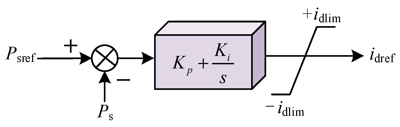
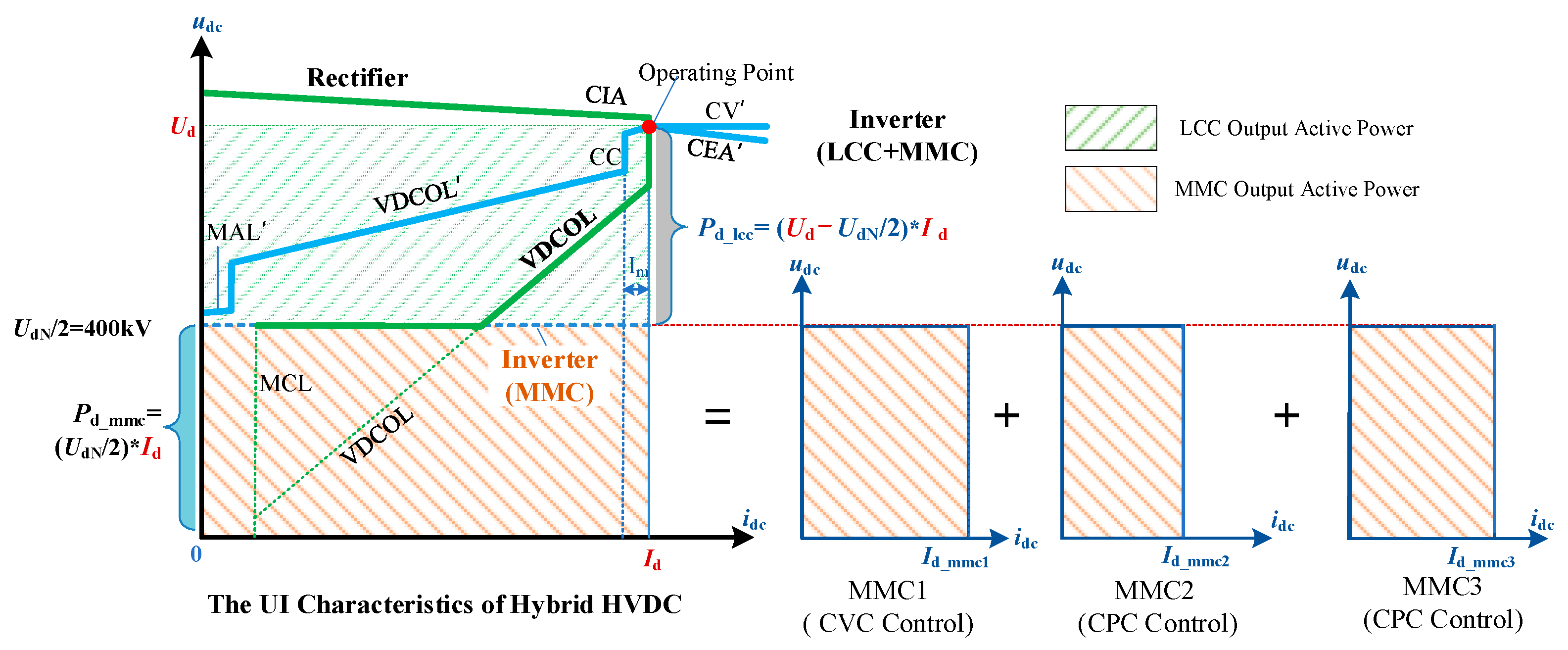
(1) Feasible control modes and respective control characteristics of hybrid HVDC are clarified. The inverters are regarded as conventional LCC cascaded with multi-infeed MMC inverters whereby a master–slave control is designed to control active power and DC voltage of MMCs. The mathematical model of the compositive hybrid HVDC system is presented, and UI curves are investigated subsequently;
(2) As a promising alternative, a multi-terminal control strategy serving AC grids’ stability improvement is proposed. Motivated by the attractively flexible and controllable characteristics, multi-objective damping controllers are designed in both sending LCC rectifier and receiving MMC inverter, which complies with damping enhancement paired with robustness assurance using the H2/H∞ control theory and LMI solution procedure;
(3) The electromagnetic simulation model of hybrid cascaded on the basis of the actual operation project is established on PSCAD/EMTDC v4.6.2 software. Simulations under different operation conditions are conducted, and the results verify the effectiveness of robust damping control methods in this study and guarantee desirable 20% damping and robust performance.
The organization of this paper is as follows.
Section 2 introduces the system configuration and master–slave control characteristics of the hybrid cascaded HVDC system.
Section 3 designs the multi-terminal control strategy to suppress the AC power disturbances.
Section 4 validates the control effect of the proposed control method using simulations based on engineering parameters.
Section 5 presents relevant conclusions in the final.
3. The Multi-Terminal Coordinated Control Method for AC Grids Based on Hybrid HVDC
It is proved that the power of the hybrid HVDC can be controlled more flexibly, so it can be applied to power oscillation control for AC grids at sending and receiving ends and enhance system stability. The coordinated control method is proposed in this Section.
3.1. Identification of Controlled AC-DC System
The operation analysis in
Section 2 presents a clear additional control advantage from the implementation point of view. In other words, viable damping controllers in both rectifiers and inverters can be designed. Thus, the control theory and specific solution procedure for the two terminal damping controller designs are disclosed in this part.
Before improving the stability of the AC-DC system, it is essential to acquire system state equations. For a single-machine system, the differential equation has a lower order and can be directly solved. However, for large-scale power grids, the state equations may reach several thousand orders, which can bring dimensionality disaster to calculations. The speed of the solution cannot be guaranteed, and it cannot satisfy real-time calculation expectations and monitoring of the power grid. Therefore, it is very important to identify the oscillation signals and reduce the order of the controlled AC-DC system. Based on the measured input/output responses, we can obtain the corresponding lower-order transfer function to design the desirable controller. This paper applies the TLS-ESPRIT identification method, which stands out among the other methods because of its robust and accurate estimation of the model. Compared to other algorithms, such as the Prony algorithm, the TLS-ESPRIT algorithm has more minor computational complexity and stronger anti-interference ability.
The TLS-ESPRIT algorithm is practicable for parameter estimation of oscillation attenuation sinusoidal signals. The key step is to form autocorrelation and cross-correlation matrices by sampling data to gain the rotation factor. Then, it is combined with TLS to calculate both amplitude and phase. The detailed identification progress of the TLS-ESPRIT algorithm is elucidated as follows.
Firstly, the multi-terminal control objects are selected as hybrid DC rectifiers, as well as inverters in CPC mode on the inverter side. Secondly, for LCC rectifiers, the input is selected as the DC current, the input is defined as the DC power for MMC inverters, and the rotor speed signal of the AC generator is chosen as the output for control. Finally, the transfer function can be calculated using the TLS-ESPRIT identification method, where small perturbations need to be excited at the input side to measure output results. As a result, the theoretical state space model
G(s) of the controlled system can be established as
where
x represents the state matrix,
u denotes the control matrix,
y is the output matrix,
Ad indicates the characteristics matrix,
bd and
cd represent the coefficient matrix of control signals, and
cd expresses the output matrix. Moreover, the dimension of
Ad varies with the system parameters.
3.2. Controller Design
Further designing additional controllers based on the
G(s) obtained from system model identification, the
H2/
H∞ hybrid robust control theory is considered to be a satisfying alternative to ensure the effectiveness of the controller under different operating conditions. Specifically, the
H2 index optimization means good system performance and anti-interference ability, while the
H∞ index optimization yields good robustness and stability. Combining the two aspect fields, the
H2/
H∞ hybrid control problem. This problem involves designing a multi-objective additional HVDC damping controller on a multi-terminal hybrid HVDC transmission system through the regional pole placement method. In this sense, the
H2/
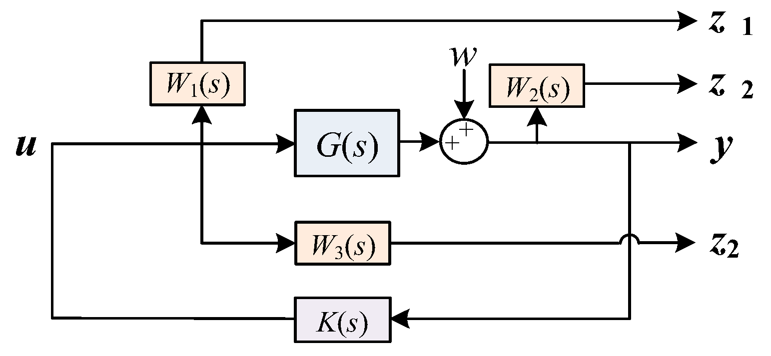
H∞ hybrid robust control has an outstanding advantage in ensuring both control effectiveness and robustness of the control process over other control methods, such as PI control. In other words, it can improve the stability of AC systems under various conditions. The proposed multi-objective control diagram is drawn in
Figure 5.
When there occurs unknown external disturbance w for controlled system G(s), W(s) indicates the weight function to evaluate the control performances, the input signals of which are selected from different links of the controlled system; noting that K(s) is the desired controller to be designed and z∞1 and z∞2 are the loops to measure H∞ performance, which can be defined as and the transfer function is , while the loop z2 is for H2 performance monitoring, which is defined as .
Before configuring with
K(s), the state space equations can be denoted as
Further, the state equations of anticipated
K(s) can be described as
where
xk are the state variables,
Ak,
Bk, and
Ck are the matrixes to be solved.
Thus, once the
K(s) is obtained, the closed-loop system can be constructed as
where
and
.
To achieve the multi-control objectives, the following three goals are decomposed: expected H2 Performance, H∞ Performance, and damping characteristics.
- (1)
H2 Performance
The
H2 norm reflects the control effort performance, the
H2 optimal control problem can be mathematically formulated as minimizing the
H2 norm defined as
with constraint
η
where
η is the given a positive real number to obtain control effort performance. The controlled system would satisfy (17) if and only if a symmetric matrix
X2 satisfies
- (2)
H∞ Performance
At the same time, for a certain positive
γ as the upper bound, to compromise with the uncertainty from
w, the
H∞ of
should be constrained as
The inequality above would be satisfied if and only if a symmetric matrix
X1 satisfies
- (3)
LMI Solution Procedure
The damping characteristic is the core of the designed controller to enhance the stability of AC grids. In other words, defining left-half
D as the desirable damping zone in
Figure 6,
D is also called a linear matrix inequality (LMI) region. The damping effectiveness is guaranteed to be equivalent to all the poles of the
G(s) within
D.
To obtain the objectives of the robust controller, the linear matrix inequality (LMI) method is applied in this paper; the details are as follows. Defining matrixes
,
and
, the symbol * indicates conjugation. If a symmetric matrix
X3 and the poles of
satisfies
Then, the poles of the controlled system are constrained in D, and the damping ratios are desirable.
- (4)
Multi-Objectives Solution
Further consider above matrix constraint conditions above, letting
, the designed
K(s) can be obtained by
where
λ1 and
λ2 are the weights of robustness and control effect, respectively. For simplicity, both
λ1 and
λ2 can be set as 0.5 in this paper.
Hence, the mixed objective controller with perfect damping ratio as well as pregnant control effectiveness and robustness to perturbation can be feasible.
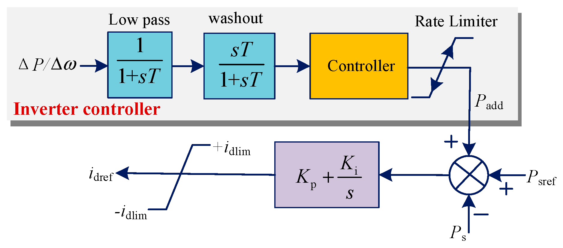
3.3. Multi-Terminal Controller for AC Grids
Based on the
H2/
H∞ robust control above, the supplementary controllers of both the rectifier LCC converter and the MMC3 inverter with CPC control can be designed, respectively, which are illustrated in
Figure 7 and
Figure 8.
5. Conclusions
The hybrid HVDC system with cascaded MMCs is applied in practical long-distance transmission projects. This study investigates both essential master–slave control characteristics and implements multi-terminal coordinated damping control to make use of its fast adjustment capacity. The main conclusions are obtained.
(1) The inverters of a hybrid cascaded HVDC transmission system can be seen as an LCC inverter in series with multi-infeed MMCs, possessing a larger transmission capacity than LCC-VSC HVDC. The characteristics of the hybrid HVDC are analyzed, and it finds that the master–slave control mode of MMCs leads to stable DC voltage and precise power control, which is more suitable for actual project operation;
(2) The power controllability of a hybrid cascaded HVDC system is more flexible, which yields an alternative for stability support for sending and receiving AC grids. We proposed a multi-terminal coordinated control method. The controllers on both the LCC rectifier and MMC inverters are designed by TLS-ESPRIT identification, H2/H∞mixed robust theory, and LMI solution procedure and both damping enhancement and robustness are guaranteed;
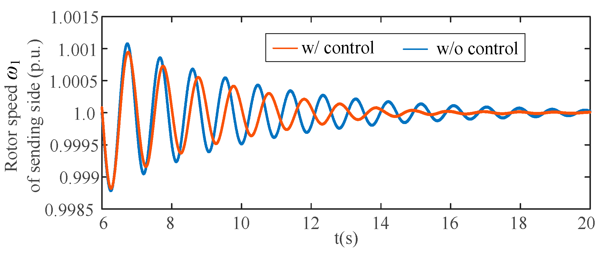
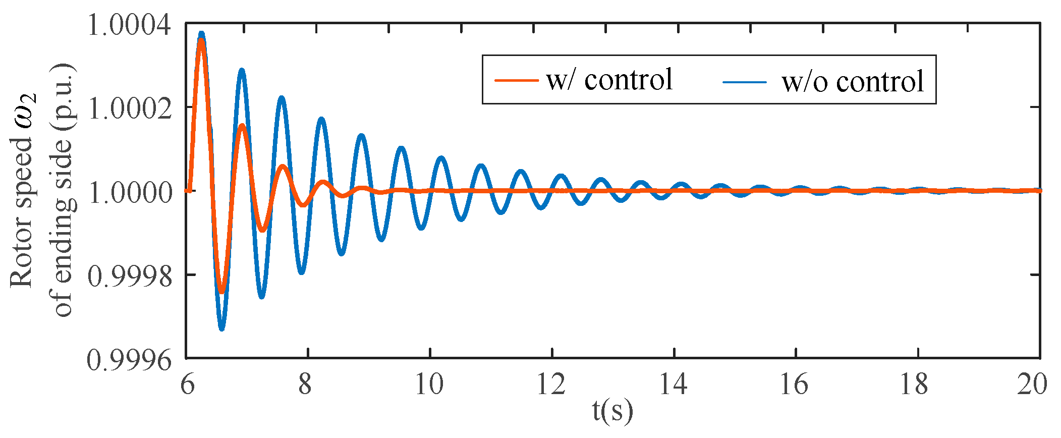
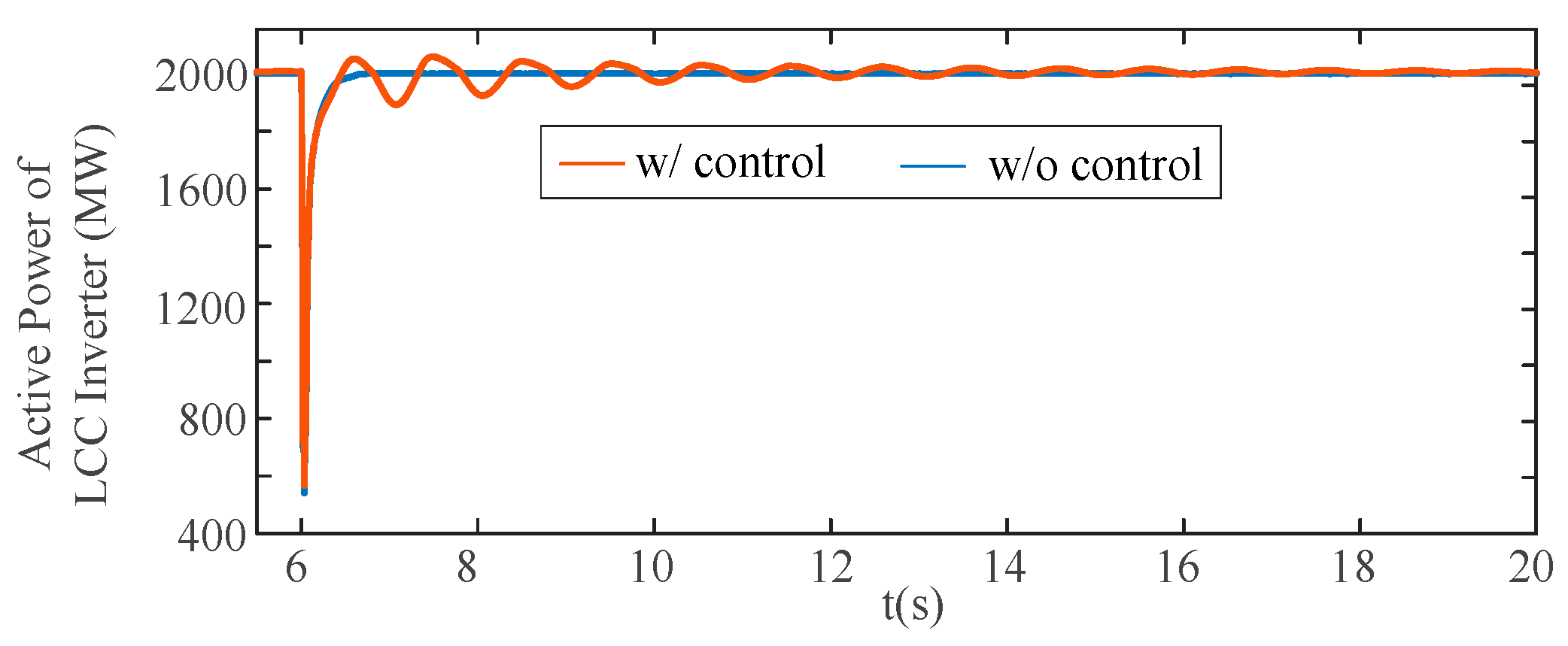
(3) Simulation results based on actual engineering parameters show satisfactory damping performance, and the proposed coordinated robust control is robust to various disturbances at both AC grids;
(4) In future studies, the integration of renewable energy and coordinated control with multiple DC lines can be further considered.


