Article

Efficient Encoding Method for Combined Codes in the MWD Telemetry System

School of Information and Communication Engineering, University of Electronic Science and Technology of China, Chengdu 611731, China
*
Author to whom correspondence should be addressed.
Electronics 2023, 12(22), 4683; https://doi.org/10.3390/electronics12224683
Submission received: 17 October 2023 / Revised: 13 November 2023 / Accepted: 15 November 2023 / Published: 17 November 2023
(This article belongs to the Special Issue Underground Wireless Communication and Information Processing)

Abstract

:
MPPM (Multipulse Position Modulation) is a pulse code technology that is widely used in optical communication and deep space communication due to its high energy efficiency. Combination code is a variation of MPPM and is widely used in MWD (Measurement While Drilling) telemetry systems. However, whether it is MPPM or combination code, it is difficult to establish a simple mapping relationship between bit symbols and pulse symbols. Therefore, an encoding table is usually used to realize the mapping between bit symbols and pulse symbols. With an increase in bit width, the storage complexity of the encoding table increases exponentially. This is unacceptable for underground transmitters working in harsh environments. This paper maps the code symbols of MPPM to a hyper-triangular region of a high-dimensional tensor and establishes a simple lookup table and lookup algorithm to achieve low-complexity mapping from bit symbols to MPPM code symbols. At the same time, this paper also provides a method for extending from MPPM code symbols to commonly used combination code symbols in MWD, thereby providing an efficient implementation path for large bit width combination code encoding at the underground end of MWD.

1. Introduction

Directional drilling is currently the most advanced drilling technology. MWD (Measurement While Drilling) telemetry technology is a core technology of directional drilling platforms. The MWD system measures and collects geological and drilling engineering parameters near the drill bit during the drilling process and transmits the collected data to the surface in real-time through the telemetry system for controlling the wellbore trajectory. Mud pulse telemetry technology uses circulating mud during the drilling process as a transmission channel. Information is transmitted to the surface by mud pressure pulses and is currently the most widely used MWD telemetry technology [1,2,3,4,5].
MPPM (Multipulse Position Modulation) [6,7,8,9] is a pulse code technology. Due to its high energy efficiency, MPPM is widely used in fields such as fiber optic communication and free-space communication because it can send more than ten bits of data with only a few pulses [10,11,12,13,14,15,16,17]. The principle of MPPM is to divide the transmission time of the code symbol of a combination code into N time slots and only select M time slots to send pulses. The bit symbols (data with a bit width of K bits) it sends are encoded in the positions of these M time slots. MPPM coding can also be combined with PSK (Phase Shift Keying) to obtain higher transmission rates through multi-mode modulation [16,17].
CC (Combination Code) is a special type of MPPM that is widely used in the mud pulse telemetry system of MWD, especially for the transmission of telemetry data in ultra-deep wells. This is because energy efficiency is very important for data transmission in ultra-deep wells. High energy efficiency can reduce the power consumption of downhole units and reduce the wear of pulse generators [18,19,20]. Baker optimized the code symbols of conventional CC codes to obtain AC (Advanced Combination) codes [19,20]. Compared with CC codes, AC codes have increased redundancy and therefore better decoding performance. This has been theoretically studied in [21].
At the downhole transmitter, bit symbols need to be mapped to corresponding code symbols before they can be sent through the pulse generator. However, it is difficult to establish a simple mapping relationship between bit symbols and CC code symbols, which makes it difficult to implement CC coding. Downhole transmitters usually generate encoding tables in advance, and the mapping from bit symbols to code symbols is implemented by table lookup. However, the space complexity of the encoding table increases geometrically as K increases. In MWD telemetry systems, the downhole working environment is harsh and the processor structure is relatively simple, making it difficult to cope with the space complexity when K is as high as 16 bits. TENKASI [22] proposed a method based on arithmetic code decompression to construct equiweight codes. Equiweight codes are channel codes with error detection capability. The number of bits equal to 1 in each code group remains constant. Therefore, equiweight codes can be used to construct MPPM symbols. Arithmetic coding is an entropy coding method with low complexity for both compression and decompression algorithms. Therefore, TENKASI’s method can achieve low-complexity mapping of MPPM bit symbols. The time complexity of TENKASI’s method is O(N2) [22]. QIN et al. [23] proposed an MPPM bit symbol mapping method for the case of M = 2. This method uses a lower triangular matrix with a certain regularity to map MPPM bit symbols to pulse positions. Each element in the matrix corresponds to a K-bit symbol, so simple mathematical calculations can be used to map K-bit binary symbols to the time slot positions of their corresponding two pulses. This method overcomes the disadvantage of exponential growth in the space complexity of encoding tables when the bit width is large, but it is only applicable to MPPM modulation with M = 2. Lin et al. [24] proposed an MPPM modulation and demodulation scheme based on an autoencoder model. The mapping from code symbols to pulse positions is achieved by training the autoencoder. The space complexity of the trained model is lower than that of the encoding table. However, the autoencoder model is only applicable to MPPM symbol modulation with specific (N, M) combinations. If the number of pulses and time slots changes, the model cannot meet the requirements of downhole combination code modulation and needs to be retrained.
Considering that MPPM (N, M) includes C N M pulse combinations, which can represent C N M different information symbols, this paper maps integer 0~ C N M − 1 to a hyper-triangular region of a high-dimensional tensor and establishes a simple lookup table to achieve simple calculation relationship between the integer and its corresponding high-dimensional tensor subscripts. The subscript corresponding to the integer is the pulse position of the MPPM symbol corresponding to the integer. This achieves low-complexity mapping from bit symbols to MPPM symbols. MPPM can be easily extended to the commonly used CC code in MWD telemetry systems, namely MPCC code. MPCC code can significantly reduce the complexity of the CC code encoding end while maintaining the same error performance.
The organization of this paper is as follows. Section 2 first gives the mathematical definition of MPPM (N, M) code symbols. Then, a regular mapping relationship between bit symbols and MPPM code symbols is established to obtain an efficient MPPM coding method. Section 3 first gives the mathematical definition of CC codes and points out the relationship between MPPM and CC codes, as well as how to generate CC code symbols from MPPM code symbols. Then, the characteristics of AC codes and their relationship with CC codes are analyzed. In Section 4, a new MPCC (Multipulse Position Check Code) is designed. The encoding complexity of MPCC codes and AC codes is compared and analyzed. Finally, through simulation, it is verified that the error performance of MPCC codes is consistent with that of AC codes. Section 5 is a summary of the entire paper.

2. Efficient Encoding Method of MPPM

For convenience of description, we first give the mathematical definition of a time slot:
Definition 1. 
A time slot is a time interval of length τ S . The time slot numbered i is denoted as:
s i [ t 0 + ( i 1 ) τ S , t 0 + i τ S ] , i = 1 , 2 , , N
where i is the time slot number,  t 0 + ( i 1 ) τ S  is the start boundary of time slot i, and  t 0 + i τ S  is the end boundary of time slot i. N consecutive time slots form a coding interval for pulse position modulation  s N = [ s 1 , s 2 , , s N ] . The set  N = { 1 , 2 , , N }  is the set of time slot numbers on the coding interval  s N .
A subset of N is used in this paper to denote those time slots of the transmitted pulse in the code element symbol of pulse position modulation (coding).

2.1. Definition of MPPM Code Element Symbols

MPPM (N, M) encodes the bit symbols by utilizing the time slots of M transmit pulses arbitrarily selected from the N time slots of s N . The code symbols are defined as follows.
Definition 2. 
A pulse position sequence  q = [ q 1 , q 2 , , q M ]  is a code element symbol of MPPM (N, M) if it represents the time slot number of the transmitted pulse, i.e.,  q i N , i = 1 , 2 , , M , and satisfies  q 1 < q 2 < < q M . The set  = { q }  consisting of all satisfying pulse position sequences on the coding interval  s N  is called the set of code element symbols of MPPM (N, M).
It is easy to obtain that the set of codeword symbols of MPPM (N, M) contains C N M different codeword symbols, and thus can encode bit symbols of bit width K = log 2 C N M , where C N M = N ! M ! N M ! , x denotes downward rounding x. The process of MPPM (N, M) encoding maps a K-bit symbol B to a codeword symbol in the set of MPPM (N, M) codeword symbols, i.e., bit-symbol mapping. Conventional bit-symbol mapping is achieved by using combinatorial mathematics to compute a sequence of all the pulse positions of N selected M and building an encoding table, and then implementing the bit-symbol mapping by looking up the table. The storage space complexity of the encoding table required for conventional bit-symbol mapping is high, especially when the bit width K of the bit symbols is large. The reason for this is the lack of a regular mapping relationship between bit symbols and codeword symbols, which prevents simple computation with bit symbols to obtain their corresponding pulse position sequences.

2.2. Efficient Encoding Method

Therefore, we consider mapping the integer 0~ C N M − 1 to an element of an M-dimensional tensor T and using the index number of the tensor element in each dimension as the pulse position of the codeword symbol mapped from the integer.

2.2.1. M = 2

When M = 2, the tensor is a two-dimensional matrix, and we map the integers to the lower triangular region of the matrix (without diagonal elements). For example, for MPPM (5, 2), we map the integers 0~9 to the two-dimensional tensor T 5 × 5 as in Figure 1.
The first dimension is denoted as R 1 , and the second dimension is denoted as R 2 . Since the diagonal is not included, the index numbers of the two dimensions corresponding to each integer satisfy R 1 < R 2 , which satisfies the encoding condition of MPPM. Also, the total number of pulse combinations of MPPM (5, 2) is 10, which exactly maps one-to-one with the elements of the lower triangular part of T 5 × 5 . Therefore ( R 1 , R 2 ) can be used as the integer corresponding to MPPM code element symbols, i.e., q = [ R 1 , R 2 ] .
Assuming that K-bit message of integer value D, the pulse number ( R 1 , R 2 ) of the corresponding combined pulse code can be easily calculated from D. Assuming that the second dimension number of D is R 2 , there are i = 1 R 2 2 i = ( R 2 1 ) ( R 2 2 ) 2 integers mapped before R 2 in each row. So, the first integer mapped in the ith row is ( R 2 1 ) ( R 2 2 ) 2 . Then, we can obtain
R 1 = D ( R 2 1 ) ( R 2 2 ) 2 + 1
Therefore, when we encode, we only need to establish a lookup table of the first integer value of each row of the second dimension. Thus, we can obtain R 2 according to the data to be encoded D, and then calculate R 1 from R 2 to obtain the encoding result of MPPM (N, 2).
Theorem 1. 
For MPPM (N, 2), construct the matrix  T N × N  by mapping the sequence of integers 0, 1, 2, … to the elements of the matrix in row-first order, starting at row 2 of the matrix. The nth row maps n − 1 integers. The total number of elements in the lower triangular region of  T N × N  thus obtained is equal to the total number of pulse combinations of MPPM (N, 2).
According to Theorem 1, it is easy to obtain that the sequence of integers 0~ C N 2 1 maps one-to-one with the elements of the lower triangular region of T N × N .
Proof of Theorem 1. 
T N × N maps the number of cells of integers as: n = 1 N 1 n = N ( N 1 ) 2 .
The number of pulse combinations for MPPM (N, 2) is
C N 2 = N ! 2 ! N 2 ! = N ( N 1 ) N 2 ! 2 ! N 2 ! = N ( N 1 ) 2
Both are equal, so the conclusion holds. □
Theorem 1 shows that the sequence of integers 0, 1, 2, … can be sequentially mapped one by one to an element of the lower triangular region of T N × N . The row and column number of this element can exactly represent a sequence of pulse positions q = [ R 1 , R 2 ] of MPPM (N, 2). If only the integers 0~ 2 K 1 , K = log 2 C N M are taken, the mapping from K-bit symbols to MPPM (N, 2) code element symbols can be realized.

2.2.2. M > 2

For MPPM (N, M) with M > 2, we can construct an M-dimensional tensor T N × N × × N M , whose indexes in each dimension are denoted as: R 1 , R 2 , ……, R M , respectively, where R i = 1 , 2 , , N . Map the integers 0~ C N M 1 sequentially to the hyper-triangular region of T. The 1st dimension is mapped from the index serial number 1, the 2nd dimension is mapped from the serial number 2, … and the Mth dimension is mapped from the serial number M. That is, the integer 0 is mapped in T ( 1 , 2 , , M ) . The index of each dimension of the elements of the mapped hyper-triangular region satisfies R 1 < R 2 < … < R M . Such a mapping ensures that the numbering on each dimension corresponding to the mapped integers satisfies the definition of the MPPM (N, M) code element notation, and thus allows for the representation of MPPM (N, M) pulse combinations. For example, the hyper-triangular region of the MPPM (5, 3) mapping is shown in Figure 2.
Based on the mapping of MPPM (5, 2) and MPPM (5, 3) to the triangular region on the two- and three-dimensional tensor T, the following law can be summarized:
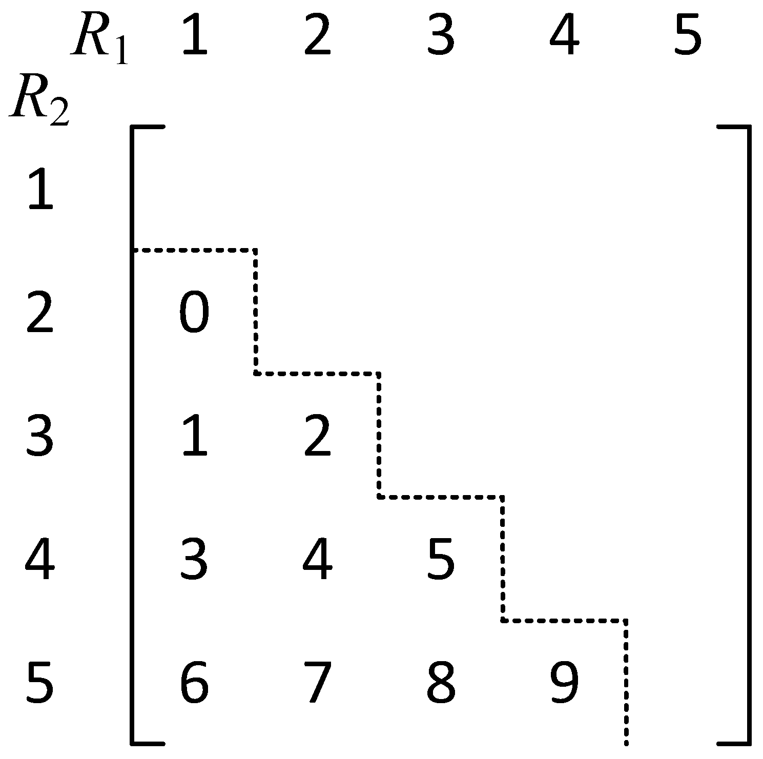
  • As can be seen from Figure 1, the two-dimensional triangular region of a two-dimensional tensor can be viewed as a cascade of multiple one-dimensional vectors. In the second dimension, the number of elements of the one-dimensional vectors mapped by indexes 2~N, respectively, is in order: 1, 2, 3, 4, …
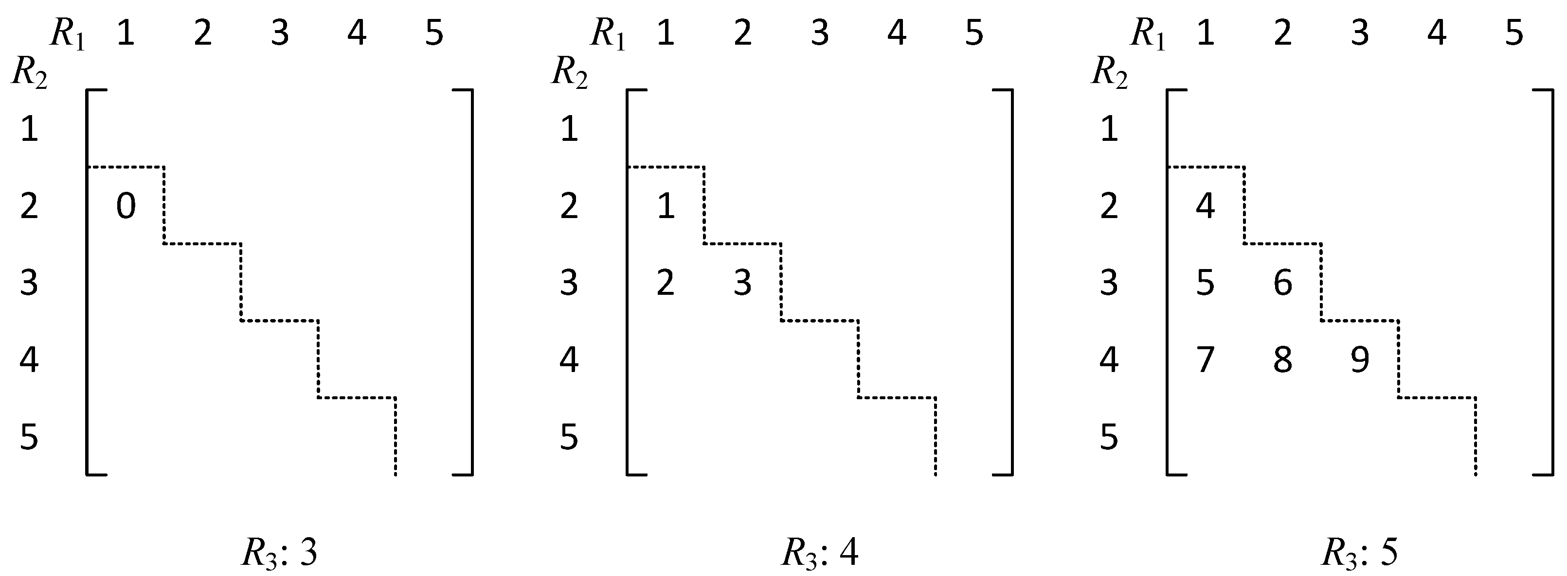
  • From Figure 2, it can be seen that the three-dimensional triangular region of a three-dimensional tensor can be viewed as a cascade of multiple two-dimensional matrices. In the third dimension, the number of elements of the two-dimensional triangular region mapped by indexes 3~N,respectively, is in order: 1, 3, 6, …
  • By analogy, the m-dimensional tensor is viewed as a cascade of m − 1 dimensional tensors. The number of elements of the m − 1 dimensional hyper-triangular region mapped by index i = m , m + 1 , , N in the mth dimension is, respectively:
    a i ( m ) = C i 1 m 1 , i = m , m + 1 , , N
The above rule can be strictly proved. To do this, first prove a theorem.
Theorem 2. 
C n + k k + 1 = j = 1 n C j + k 1 k
Proof of Theorem 2. 
From the constant equation C n k = C n 1 k 1 + C n 1 k :
C n + k k + 1 = C n + k 1 k + C n + k 1 k + 1 = C n + k 1 k + C n + k 2 k + C n + k 2 k + 1 = = i = 1 n 1 C n + k i k + C k + 1 k + 1 = i = 1 n C n + k i k
Let n i = j 1 , then j = n i + 1 = 1 , , n , so that we obtain
i = 1 n C n + k i k = j = 1 n C j + k 1 k
Theorem 3. 
Map the integers 0~ C N M 1  sequentially to the hyper-triangular region of m-dimensional tensor T. The m-dimensional hyper-triangular region can be regarded as a stack of m − 1 dimensional hyper-triangular regions. In dimension m, the number of integers on the m − 1 dimensional hyper-triangular region mapped by the nth layer where  n = m , m + 1 , N  is
a n ( m ) = C n 1 m 1 , n = m , m + 1 , N
Proof of Theorem 3. 
Prove by mathematical induction.
  • On dimension two: integers are mapped onto elements of the lower triangular region of the two-dimensional tensor. The mapping starts at the beginning, so on dimension two, the number of integers mapped in the nth row is n 1 , n = 2 , 3 , , N :
    a n ( 2 ) = n 1 = C n 1 1 , n = 2 , 3 , , N
  • On dimension three: the three-dimensional tensor can be viewed as consisting of a two-dimensional tensor layered on dimension three. The number of integers mapped on dimension three, starts from the beginning, and therefore the number of integers mapped on the nth layer is:
    a n ( 3 ) = i = 2 n 1 a i ( 2 ) = i = 2 n 1 i 1 = ( n 1 ) ( n 2 ) 2 = C n 1 2       , n = 3 , , N
  • Assuming that the conclusion holds in dimension m, start the mapping from R m = m , i.e.,
    a n ( m ) = i = m 1 n 1 a i ( m 1 ) = C n 1 m 1     , n = m , m + 1 , N
  • Then, the mapping from R m + 1 = m + 1 on dimension m + 1 has
    a n ( m + 1 ) = i = m n 1 a i ( m ) = i = m n 1 C i 1 m 1 , n = m + 1 , m + 2 , , N
Let j = i m + 1
a n ( m + 1 ) = i = m n 1 C i 1 m 1 = j = 1 n m C j + m 2 m 1     , n = m + 1 , m + 2 , , N
Let k = n m , i.e.,
a k + m ( m + 1 ) = j = 1 k C j + m 2 m 1     , k = 1 , 2 , , N m
By Theorem 2
a k + m ( m + 1 ) = j = 1 k C j + m 2 m 1 = C k + m 1 m     , k = 1 , 2 , , N m
i.e.,
a n ( m + 1 ) = C n 1 m     , n = m + 1 , m + 2 , , N
Therefore, the conclusion of a n ( m + 1 ) = C n 1 m , n = m + 1 , m + 2 , , N also holds in dimension m + 1. That is, the conclusion of a n ( m ) = C n 1 m 1 , n = 1 , , N m + 1 holds. □
Theorem 4. 
For an M-dimensional tensor  T N × N × × N M , the number of elements of the mapped super-triangular region is equal to the total number of pulse combinations of MPPM (N, M) as  C N M .
Proof of Theorem 4. 
The total number of integers mapped in the M-dimensional super-triangular region is:
K = i = M N a i ( M ) = i = M N C i 1 M 1
Let j = i M + 1 , then
K = j = 1 N M + 1 C j + M 2 M 1
According to the conclusion of Theorems 2 and 3, it is then obtained that:
K = j = 1 N M + 1 C j + M 2 M 1 = C N M
By Theorem 4, it follows that the pulse codewords of MPPM (N, M) map one-to-one with the supra-triangular region of the M-dimensional tensor.

2.2.3. LUT (Lookup Table) Algorithm for MPPM (N, M) Bit-Symbol Mapping

When mapping integers 0~ C N M 1 sequentially to the super triangular region of T, using a n ( m ) we can determine the number of integers mapped at each level in any dimension. From this, we can use a n ( m ) to construct a LUT, e.g., we can construct N max = 24 , M max = 6 lookup table T L U T to satisfy the MPPM coding requirement of 1~16-bit width. It is a matrix with M max rows and N max columns.
A simple lookup table algorithm can be designed using U L U T to encode MPPM (N, M) of 1 to 16 bits, N N max , M M max . Since U L U T contains the number of elements in each layer of each dimension of the hyper-triangular region mapped on the M -dimensional tensor T, the index q = [ R 1 , R 2 , , R M ] of the integer corresponding to each dimension of T can be computed from any integer between 0~ C N M 1 . Taking q as a codeword symbol of the MPPM (N, M) can realize the mapping of bit symbols to the codeword symbols of the MPPM (N, M), which can greatly reduce the space complexity at the coding end of the MPPM (N, M). The LUT algorithm for MPPM (N, M) coding is as follows Algorithm 1:
Algorithm 1. LUT algorithm for MPPM (N, M) coding.
1: Initialization:
2:  [ q 1 , q 2 , , q M ] = 0
3: B = K-bit data to be encoded
4: Look up the table to calculate [ q 1 , q 2 , , q M ] :
5: Index of the 1st element greater than B in row M of R m = T L U T : q M = R m ;
6: for (m decreases from M to 2)
7:  B = B − T L U T ( m , R m 1 )
8:  Index of the 1st element greater than B in the m − 1st row of R m = T L U T
9:   q m 1 = R m
10: end
Since each row of T L U T is arranged in ascending order, it has low lookup complexity.

3. CC Code and AC Code

The mud pulse channel operated by the MWD telemetry transmission system is a poor channel characterized by strong interference, nonlinearity, and multipath transmission. In order to improve the transmission performance in the mud pulse channel, the CC (N, M) code, which is widely used in the MWD telemetry transmission system, extends the minimum hourly slot spacing between neighboring pulses in the MPPM (N, M) code element symbols in order to reduce the interference between pulses caused by the mud channel. The code element symbols of the CC (N, M) code and its set of code element symbols are defined as [19,20]:
Definition 3. 
If a sequence of pulse positions  p = [ p 1 , p 2 , , p M ] , where  p i N , i = 1 , 2 , , M  and  p 1 < p 2 < < p M , satisfies the following conditions:
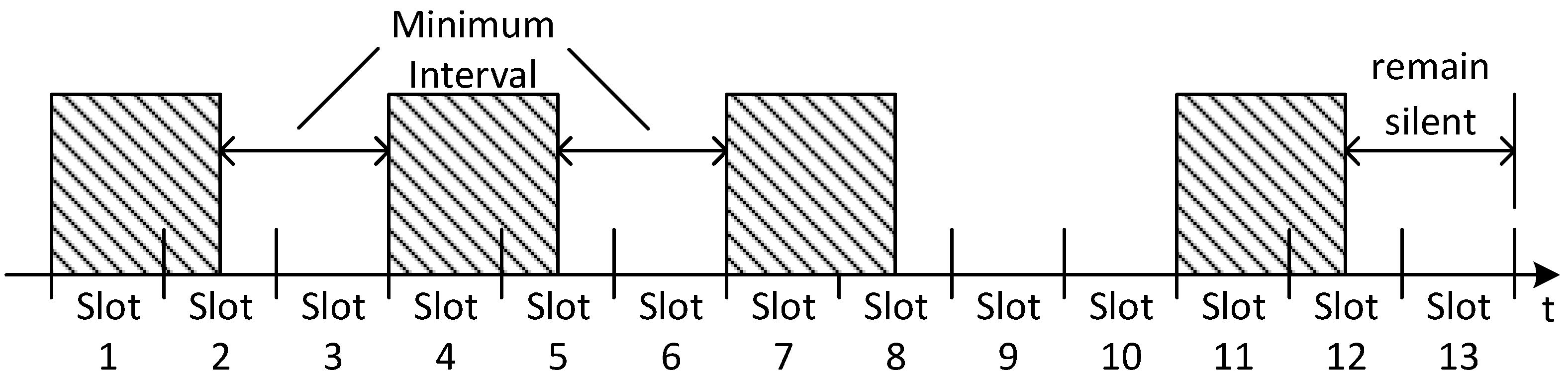
  • the interval between adjacent pulses is at least 2 time slots, i.e., the difference between the time slot numbers of adjacent pulses is greater than or equal to three;
  • the last two time slots of each code element symbol remain silent. This is the requirement that the interval between the last pulse and the first pulse of the next code element symbol be at least 2 time slots.
Then,  p  is called a code element symbol of a CC (N, M) code. The set  = { p }  consisting of all satisfying pulse position sequences on the coding interval  s N  is called the set of code element symbols of a CC (N, M) code.
From the definition of MPPM (N, M) and CC (N, M), it can be easily obtained that by inserting two silent time slots to extend the pulse interval after each pulse of the code element symbol of MPPM (N, M), the code element symbol of CC (N + 2M, M) can be obtained. That is, assuming that q = [ q 1 , q 2 , , q M ] is the code element symbol of MPPM (N, M), the pulse interval expansion of q yields a new pulse sequence p = [ p 1 , p 2 , , p M ] , where p i = q i + 2 ( i 1 ) . Then, p is a code element symbol of a CC (N + 2M, M) code.
Meanwhile, in order to further improve the pulse detection performance, Baker’s AC code is preferred on the basis of CC code, and the code element symbols with i = 1 M p i even or odd are selected to represent the information, i.e., it is equivalent to a parity check. At the same time, in order to improve the pulse energy, the AC code specifies that the pulse width is 3/2 time slots [19,20]. The code element symbol of an AC code is shown in Figure 3.

4. Multipulse Position Checksum Code (MPCC)

4.1. Principles of MPCC Coding
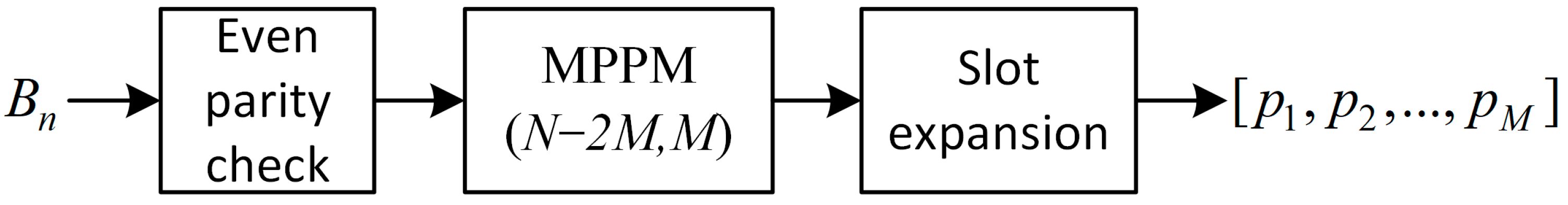
On the basis of solving the coding complexity of MPPM (N, M), this paper designs a coding method of combinational code with parity check capability, i.e., MPCC (Multipulse Position Checksum Code). The coding principle of MPCC code is shown in Figure 4.
Suppose B n is n bits of data to be encoded. Firstly, B n is parity-checked, expanded to n + 1 bits and then the pulse position is encoded with n + 1 bits of MPPM. Finally, the MPPM encoded pulse positions are extended with time slots, i.e., two time slots are inserted after each pulse to obtain a pulse coding sequence that satisfies the constraints of pulse width and time slots of Baker’s AC code, and also has the capability of even-checking. MPCC encoding has the equivalent performance of the AC code, but with a reduced coding complexity. The encoding flow of MPCC is as follows:
Assume that the data to be encoded are denoted as B n = [ b n 1 , b n 2 , , b 0 ] and n denotes the bit width.
  • First parity check B n , transformed to n + 1 bits, denoted as D n + 1 = [ B n , P e v e n ] , where P e v e n is the even parity bit of b n 1 , b n 2 , , b 0 .
  • Perform n + 1-bit MPPM (N, M) modulation on D n + 1 to obtain the pulse train [ q 1 , q 2 , , q M ] of the MPPM coded output.
  • [ q 1 , q 2 , , q M ] undergoes time slot expansion to obtain the MPCC (N + 2M, M) output [ p 1 , p 2 , , p M ] , where p i = q i + 2 ( i 1 ) , i = 1 , 2 , , M .

4.2. Analysis of Coding Complexity

Assume that the bit width range of the bit symbols to be encoded at the coding side is k = 1 , 2 , , K bits, and the bit symbols of each bit width are encoded using M P M M ( N k , M k ) . According to Table 1, the LUT of MPCC code has M max = M k rows and N max = N k integers per row. Since the integers in each row of the LUT are in ascending order, the lookup table algorithm can use Binary Search Algorithm [25]. The maximum number of Binary Search in a row is not more than log 2 N k + 1 . Encoding a k-bit symbol requires M k binary searches, and the total number of searches is not more than M k log 2 N k + 1 . Therefore, the time complexity of MPCC encoding is O M k log 2 N k . MPCC encoding only needs to store the LUT of size M k × N k , so its space complexity is O M k N k .
For k-bit wide bit symbols, AC coding requires an encoding table of size 2 k to realize the mapping of bit symbols to pulse positions. The coding process of AC codes is to index the encoding table directly using the bit symbols, and thus the time complexity of AC coding is O 1 , while AC coding requires the storage of the complete encoding table of size 2 k . Usually, we choose M k and N k to satisfy that the number of combinations of pulse positions C N k M k should be just greater than the total number of k-bit symbols, 2 k , in order to minimize the redundancy, i.e., 2 k C N M 2 k + 1 . The space complexity of AC coding to store a k-bit encoding table can thus be obtained as O 2 k = O C N M .
In practice, AC coding needs to store all the encoding tables corresponding to k = 1 , 2 , , K bit widths, i.e., the total space size of encoding tables is k = 1 K 2 k , whereas MPCC only needs to store one LUT of size M k × N k . Therefore, compared with AC coding, although the time complexity of MPCC coding is slightly higher than that of AC coding, its space complexity is much smaller than that of AC coding, which effectively solves the problem that the space complexity of AC coding increases exponentially with the increase in the bit width k of bit-symbol. The spatial and temporal complexity of MPCC and AC coding schemes are shown in Figure 5.

4.3. BER Performance Analysis of MPCC and AC Codes

In order to verify that the BER performance of MPCC codes remains the same as that of AC codes despite the reduced coding complexity, BER performance simulations under Gaussian channels were carried out in this paper. The simulation conditions were as follows:
  • The coding parameters of the MPPM code are shown in Table 2.
Table 2. MPPM Code M and N Parameter Table.
Bit WidthMNBit WidthMN
1129413
21410415
32511417
42712516
52913518
63914618
731115620
831316622
17624
2.
The coding parameters of the AC code are shown in Table 3.
Table 3. AC Code M and N Parameter Table.
Bit WidthMNBit WidthMN
1149423
22910425
321111526
421312528
531513630
631714632
731915634
842116636
After expanding the MPPM parameters from Table 2 to MPCC coding, the MPCC coding parameters were the same as the AC codes in Table 3. MPCC coding and AC coding were performed for random data streams with 4 bit, 8 bit, and 16 bit bit widths, respectively, and the modulated pulse signals were passed through the AWGN channel, and the SER (Symbol Error Ratio) performance curve is shown in Figure 6 by using E s / N 0 and error symbol rate to measure the error symbol performance.
It can be seen that regardless of whether data width is 4-bit, 8-bit or 16-bit, the error symbol performance of MPCC code is exactly the same as that of AC code.

5. Conclusions

Pulse combination coding technology based on AC codes is widely used in the field of telemetry measurement while drilling. To achieve mapping from bit symbols to code symbols, the encoding table needs to be stored in advance at the downhole encoding end. However, due to the complex and harsh downhole environment, the space complexity of the encoding table cannot be met by the downhole processor system. This paper constructs a new combination code, namely MPCC code. MPCC code maps bit symbols to code symbols through a lookup table with much lower space complexity than encoding tables. MPCC code effectively solves the problem of exponential growth of the space complexity of encoding tables with increasing bit width and has the same error performance as AC codes in Gaussian channels. Compared with AC codes, MPCC codes are more suitable for systems with limited storage resources on the transmitting side, such as MWD telemetry systems.

Author Contributions

Conceptualization, W.C.; Methodology, W.C.; Software, W.C., X.L. and C.Y.; Validation, Q.G.; Data curation, J.L.; Writing—original draft, J.L.; Writing—review & editing, W.C.; Project administration, Q.G.; Funding acquisition, W.C. All authors have read and agreed to the published version of the manuscript.

Funding

This research was funded by [National Key Research and Development Program of China] grant number [2017YFC0307103-2] and [China National Offshore Oil Corporation] grant number [KJGG-2022-1402]. And The APC was funded by [KJGG-2022-1402].

Data Availability Statement

Data are contained within the article.

Acknowledgments

Thanks to Zhang Songwei for his help and meaningful suggestions.

Conflicts of Interest

The authors declare no conflict of interest.

References

  1. Patton, B.; Gravley, W.; Godbey, J.; Sexton, J.; Hawk, D.; Slover, V.; Harrell, J. Development and Successful Testing of a Continuous-Wave Logging-While-Drilling Telemetry System. J. Pet. Technol. 1977, 29, 1215–1221. [Google Scholar] [CrossRef]
  2. Qu, F.; Jiang, Q.; Jin, G.; Wei, Y.; Wang, Z. Noise Cancellation for Continuous Wave Mud Pulse Telemetry Based on Empirical Mode Decomposition and Particle Swarm Optimization. J. Pet. Sci. Eng. 2020, 200, 108308. [Google Scholar] [CrossRef]
  3. Yang, B.; Chen, W.; Wang, W.; Guo, G. Noise Modeling and Deep Learning Noise Suppression of Mud Signal. In Proceedings of the IEEE Conference on Industrial Electronics and Applications (ICIEA), Chengdu, China, 16–19 December 2022; pp. 1354–1359. [Google Scholar]
  4. Wei, C.; Peipei, J.; Qingshui, G.; Songwei, Z. A trellis coded pulse interval modulation for measurement while drilling telemetry. In Proceedings of the IEEE Conference on Industrial Electronics and Applications (ICIEA), Hefei, China, 5–7 June 2016; pp. 522–525. [Google Scholar]
  5. Shao, J.; Yan, Z.; Han, S.; Li, H.; Gao, T.; Hu, X.; Wei, C. Differential signal extraction for continuous wave mud pulse telemetry. J. Pet. Sci. Eng. 2017, 148, 127–130. [Google Scholar] [CrossRef]
  6. Sugiyama, H.; Nosu, K. MPPM: A method for improving the band-utilization efficiency in optical PPM. J. Light. Technol. 1989, 7, 465–472. [Google Scholar] [CrossRef]
  7. Peppas, K.P.; Boucouvalas, A.C.; Ghassemloy, Z. Performance of underwater optical wireless communication with multi-pulse pulse-position modulation receivers and spatial diversity. IET Optoelectron. 2017, 11, 180–185. [Google Scholar] [CrossRef]
  8. Park, H.; Barry, J.R. Trellis-coded multiple-pulse-position modulation for wireless infrared communications. IEEE Trans. Commun. 2004, 52, 643–651. [Google Scholar] [CrossRef]
  9. Velidi, R.; Georghiades, C.N. Frame synchronization for optical multi-pulse pulse position modulation. IEEE Trans. Commun. 1995, 43, 1838–1843. [Google Scholar] [CrossRef]
  10. Phillips, A.; Cryan, R.; Senior, J. Performance evaluation of optically preamplified PPM systems. IEEE Photon. Technol. Lett. 1994, 6, 651–653. [Google Scholar] [CrossRef]
  11. Kiasaleh, K. Performance of APD-based, PPM free-space optical communication systems in atmospheric turbulence. IEEE Trans. Commun. 2005, 53, 1455–1461. [Google Scholar] [CrossRef]
  12. Edwards, B.L.; Israel, D.; Wilson, K.; Moores, J.D.; Fletcher, A.S. The laser communications relay demonstration. In Proceedings of the 2012 International Conference on Space Optical Systems and Applications (ICSOS), Ajaccio, Corsica, France, 9–12 October 2012; pp. 1–9. [Google Scholar]
  13. Landolsi, T.; Elrefaie, A. Performance evaluation of optically preamplified PPM systems with dual-polarized ASE noise and finite extinction ratios. IEEE Trans. Commun. 2014, 62, 3644–3651. [Google Scholar] [CrossRef]
  14. Landolsi, T.; Elrefaie, A. Error performance of preamplified optical PPM systems with finite extinction ratios. J. Opt. Fiber Technol. 2014, 20, 365–368. [Google Scholar] [CrossRef]
  15. Gao, D.; Li, T.; Xie, Z.; He, Y.; Han, X.; Jia, S.; Wang, W.; Xie, X. Performance evaluation of the high-speed deep-space optical communication system assisted by preamplified thresholded pulse-position modulation. Front. Phys. 2022, 10, 904. [Google Scholar] [CrossRef]
  16. Wang, F.; Hu, G.; Du, T.; Sun, Y.; Hao, X.; Chen, J.; Wu, P. Performance research of mPPM-QPSK modulation signal for free space optical communication. Opt. Commun. 2020, 457, 124646. [Google Scholar] [CrossRef]
  17. Yu, M.; Guo, H.; Liu, Y.; Li, Y.; Qiu, J.; Hong, X.; Li, W.; Zuo, Y.; Wu, J. Improved Two Modulus Equalization Algorithm for MPPM-QPSK Optical Communication System. Acta Opt. Sin. 2021, 41, 1906004. [Google Scholar]
  18. Rorden, L.H. Combinatorial Coded Telemetry in Mwd. U.S. Patent 004908804, 13 March 1990. [Google Scholar]
  19. Tu, B. MWD Mud Pulse Signal Identification and Ground Adaptation Technology Research. Diploma Thesis, Beijing University of Technology, Beijing, China, 2013; pp. 48–52. [Google Scholar]
  20. Guo, C. Research on Mud Positive Pulse Signal Processing Method Based on Combinatorial Code. Diploma Thesis, China University of Petroleum (East China), Qingdao, China, 2020; pp. 9–19. [Google Scholar]
  21. Sato, K.; Ohtsuki, T.; Sasase, I.; Mori, S. Performance analysis of (m, 2) MPPM with imperfect slot synchronization. In Proceedings of the Communications, Computers and Signal Processing, 1993, IEEE Pacific Rim Conference on IEEE, Victoria, BC, Canada, 19–21 May 1993; pp. 765–768. [Google Scholar]
  22. Ramabadran, T.V. A coding scheme for m-out-of-n codes. IEEE Trans. Commun. 1990, 38, 1156–1163. [Google Scholar] [CrossRef]
  23. Qin, L.; Ke, X. A Study of Mapping Scheme for Dual-Pulse MPPM. J. Xi’an Univ. Technol. 2007, 23, 269–272. [Google Scholar] [CrossRef]
  24. Lin, Z.; Wang, X.; Wu, N. Realization of multi-pulse position modulation based on autoencoder. Opt. Commun. Technol. 2022, 46, 28–34. [Google Scholar] [CrossRef]
  25. Yan, W.; Li, D.; Wu, W. Data Structure in C, 2nd ed.; Posts & Telecom Press: Beijing, China, 2021. [Google Scholar]
Figure 1. MPPM (5, 2) mapping of a 2D triangular region.
Electronics 12 04683 g001
Figure 2. MPPM (5, 3) mapping of 3D triangular regions.
Electronics 12 04683 g002
Figure 3. Schematic of AC code pulse position and pulse width.
Electronics 12 04683 g003
Figure 4. MPCC (N, M) coded modulation principle.
Electronics 12 04683 g004
Figure 5. Spatial and temporal complexity of MPCC and AC coding schemes.
Electronics 12 04683 g005
Figure 6. Symbol error rate performance of MPCC and AC coding schemes.
Electronics 12 04683 g006
Table 1. MPPM lookup table U L U T for N max = 24 , M max = 6 .
m a n ( m )
11, 2, 3, 4, 5, 6, 7, 8, 9, 10, 11, 12, 13, 14, 15, 16, 17, 18, 19, 20, 21, 22, 23, 24
20, 1, 3, 6, 10, 15, 21, 28, 36, 45, 55, 66, 78, 91, 105, 120, 136, 153, 171, 190, 210, 231, 253, 276
30, 0, 1, 4, 10, 20, 35, 56, 84, 120, 165, 220, 286, 364, 455, 560, 680, 816, 969, 1140, 1330, 1540, 1771, 2024
40, 0, 0, 1, 5, 15, 35, 70, 126, 210, 330, 495, 715, 1001, 1365, 1820, 2380, 3060, 3876, 4845, 5985, 7315, 8855, 10,626
50, 0, 0, 0, 1, 6, 21, 56, 126, 252, 462, 792, 1287, 2002, 3003, 4368, 6188, 8568, 11,628, 15,504, 20,349, 26,334, 33,649, 42,504
60, 0, 0, 0, 0, 1, 7, 28, 84, 210, 462, 924, 1716, 3003, 5005, 8008, 12,376, 18,564, 27,132, 38,760, 54,264, 74,613, 100,947, 134,596
Disclaimer/Publisher’s Note: The statements, opinions and data contained in all publications are solely those of the individual author(s) and contributor(s) and not of MDPI and/or the editor(s). MDPI and/or the editor(s) disclaim responsibility for any injury to people or property resulting from any ideas, methods, instructions or products referred to in the content.

