Abstract
Ultra-wideband (UWB) systems promise centimetre-level accuracy for indoor positioning, yet they remain susceptible to non-line-of-sight (NLOS) errors due to complex indoor environments. A fusion mechanism that integrates the UWB with an odometer sensor is introduced to address this challenge and achieve a high positioning accuracy. A sliding window method is applied to identify NLOS anchors effectively. The modified UWB-only positioning has an average error under 13 cm with an RMSE of 16 cm. Then, a loosely coupled approach named Dynamic Dimension Fusion (DDF) is designed to mitigate the odometer’s cumulative errors that achieve a remarkable average error and RMSE below 5 cm, notably superior to established unscented Kalman filter (UKF) fusion techniques. DDF utilises UWB data to correct the one-dimensional heading error of the odometer when the robot moves in a straight line and to correct both heading and mileage in two dimensions when the robot is turning. Comprehensive real-world experimental evaluations underscore the efficacy and robustness of this novel approach.
1. Introduction
In recent years, the rapid development of the Internet of Things (IoT) and robotics technology has significantly expanded the application scenarios for indoor robots. In industrial settings, intelligent warehouse management can be achieved through collaboration among various types of Automated Guided Vehicles (AGVs), leading to enhanced efficiency and reduced labour costs. Meanwhile, indoor sweeping robots have gained increasing popularity in daily life scenarios. The advancement of technologies such as IoT systems, virtual reality (VR), and augmented reality (AR) has raised higher demands on the accuracy and stability of indoor positioning systems. While GNSS can provide precise meter-level positioning in outdoor environments [1,2], it is not applicable indoors due to signal attenuation caused by obstacles.
In order to achieve indoor positioning, researchers have employed various methodologies, including WIFI, Bluetooth, UWB, Inertial Measurement Units (IMU), Odometer, Visual, and LiDAR. The utilisation of WIFI for indoor positioning offers the advantage of its extensive adoption spanning several decades; most indoor environments are already equipped with WIFI base stations. Using these base stations for positioning purposes can reduce hardware costs [3]. The issue of WIFI positioning lies in the accuracy achieved in the process. The study conducted by Satish et al. [4] demonstrated that despite the joint correction of support vector regression (SVR) and Kalman filter (KF), the accuracy of the WiFi positioning system remains suboptimal, with an error margin of 0.8528 m. One of Bluetooth’s key advantages lies in its extensive ubiquity. Most mobile devices, including smartphones and laptops, have Bluetooth functionality. Additionally, Apple has introduced the iBeacon, a Bluetooth-enabled location tag [5]. Bluetooth Low Energy (BLE) technology has empowered numerous small-scale platforms with limited battery capacity to offer prolonged and consistent positioning capabilities. In a study by Fernando et al. [6], nine distinct algorithms for fingerprint-based BLE positioning were compared. The Weighted k-Nearest Neighbors (Wk-NN) algorithm demonstrated the highest accuracy, achieving a positioning error of only 0.68 m. On the other hand, the Independent Gaussian Distribution (IGD) algorithm yielded less precise results, with an error of 10 m in various experimental trials. Consequently, WIFI and Bluetooth technologies face a standard limitation—they typically provide positioning at the meter-level to decimeter level, making it challenging to meet the demands for centimetre-level indoor positioning in future industries.
Indoor positioning systems frequently employ vision and laser-based technologies for localisation and mapping within uncharted environments. Vision-oriented techniques deploy monocular or stereo cameras, leveraging them to identify and monitor various features within indoor settings, subsequently translating these visual indications into spatial coordinates. One salient advantage of employing cameras lies in their passive nature, ensuring they do not emit signals. This characteristic is crucial in mitigating interference, especially within compassionate environments. However, this approach is not without its challenges: fluctuations in ambient lighting, potential occlusions, and surfaces lacking texture can considerably impede the precision of localisation. For instance, Qayyum and Kim’s research [7] utilised an RGB-G camera with an IMU for UAV positioning, attaining a localisation accuracy of below 0.2 m in terms of the RMSE. LiDAR technology, renowned for its pinpoint accuracy in indoor spaces, operates through an active sensing mechanism. Emitting laser beams to gauge distances ensures unwavering performance, unaffected by variations in light conditions. Nonetheless, LiDAR devices carry a premium price tag and encounter challenges from surfaces with high reflectivity. Furthermore, transparent obstacles, such as glass panels, can potentially skew their scanning precision [8].
UWB technology has emerged as a prominent area of inquiry in recent years within the domain of indoor positioning systems. UWB employs nanosecond-level pulse modulation for communication, utilising frequencies from 3.1 GHz to 10.6 GHz, boasting bandwidths ranging from hundreds of megahertz to several gigahertz. These distinctive attributes confer upon UWB notable traits such as low power consumption, resistance to multipath propagation, and minimal interference [9,10]. Furthermore, UWB can meticulously measure signal time-of-flight under ideal conditions, facilitating precise ranging with centimetre-level accuracy. Nevertheless, due to the intricate nature of indoor environments, impediments, including structural elements like walls, tables, chairs, and human presence, may impede direct line-of-sight (LOS) communication between the UWB tag and the anchor point, resulting in NLOS errors. The magnitude of NLOS errors varies, extending from a few centimetres to several meters, depending on the obstructing elements’ material composition and diffraction angles. In the experimental investigations conducted by Hao et al. [11], NLOS discrepancies induced by a 0.7-m-thick concrete pillar could exceed 3 m. The study posits the viability of redressal for NLOS errors by developing an error model for diffracted waves, potentially increasing accuracy by up to 80%. The discernment and amelioration of NLOS errors constitute a central thrust within UWB-based indoor positioning system research. In recent years, various scholars have embarked upon various methodologies to grapple with this challenge. Some have advocated residual-based approaches, as elucidated by Jingwang et al. [12], which entail the identification of NLOS instances predicated upon variations in the standard deviation of ranging values, followed by employing Kalman filtering for error rectification. Others have pursued avenues predicated upon scrutinising channel impulse response (CIR) attributes, as expounded by Chunxue et al. [13], who advocate for selecting higher-fidelity anchor point data through CIR analysis, leading to a discernible 40% abatement in the RMSE associated with positioning. Further inquiries have been directed towards modelling specific obstacles through statistical descriptors, as evidenced by [14,15,16], which principally concentrate on NLOS errors engendered by human presence. Concurrently, the advent of machine learning (ML) methodologies, including Support Vector Machine (SVM) [17,18,19] long short-term memory (LSTM) [20], has demonstrably catalysed the in-depth scrutiny of CIR and received signal strength (RSS) attributes, affording a vantage point for the formulation of error models. Different AI algorithms have their drawbacks; for instance, SVM’s drawback is that it requires longer training time and cannot handle noisy data well [21], and LSTM requires a lot of computation and memory, which is not friendly to the miniaturisation of the carrier.
These methods somewhat mitigate the impact of NLOS errors on positioning accuracy. However, providing consistent and accurate positioning data in complex and changing indoor environments using only one sensor is difficult. Consequently, the integration of multiple sensors represents an inexorable progression. Through multi-sensor fusion, the system not only aids UWB technology in identifying and mitigating NLOS errors to enhance positioning precision but also augments the system’s resilience in demanding environmental conditions. Commonly integrated sensors with UWB encompass IMU [22,23], Visual [24], odometers [25], and LiDAR [26]. Among these, wheeled odometers have historically received less attention from researchers, primarily due to their constrained applicability, typically limited to two-dimensional vehicular movement in scenarios involving wheeled AGVs. Nonetheless, wheeled odometers are uncomplicated, cost-effective sensors immune to extraneous electromagnetic interference. This makes them suitable for low-cost robotic platforms or those functioning in intricate electromagnetic environments. The advancement of optoelectronic technology has led to notable enhancements in the sampling frequency and precision of wheeled odometers, rendering them highly suitable for integration within a UWB-based fusion positioning system.
The Kalman filter (KF) is a pivotal algorithm in multi-sensor fusion. Established as a recursive filter for linear systems, the KF’s significance remains undiminished despite its longstanding introduction. For instance, in the study by Kim et al. [27], the KF was employed to integrate data from UWB and IMU. The resulting fused system achieved a positioning precision of approximately 0.4 m, even in challenging NLOS conditions.
The evolution of the KF led to the development of the Extended Kalman Filter (EKF) and the UKF, both tailored to address nonlinear system requirements. The EKF achieves this by linearising the nonlinear system through the Jacobian matrix, subsequently applying the KF. In research conducted by Li et al. [28], the EKF was utilised to integrate UWB, IMU, and odometer data. Notably, under conditions where UWB operated strictly in LOS, the combined system’s Root Mean Square Error (RMSE) was 3.29 cm. For UWB alone, this error margin was slightly larger, at 4.66 cm. However, the EKF’s primary limitation arises from its linearisation process, which can introduce inaccuracies. Moreover, the EKF may prove unstable in contexts of intense nonlinearity.
In contrast, the UKF mitigates linearisation issues by employing sigma points for unscented transformation, yielding more accurate state estimates. A comparative study by Krishnaveni et al. [29] examined the EKF and UKF localisation outcomes when fused with UWB and IMU under identical conditions. Their findings underscored the UKF’s superior performance over the EKF.
Particle filtering, on the other hand, employs a particle cloud to represent the system’s state, updating weights iteratively. While capable of addressing strongly nonlinear systems, its computational demands escalate with an increase in particle count. In a study by Jia et al. [30], particle filtering was used to merge UWB, LiDAR, and odometry data, achieving an RMSE of 5 cm in environments with weak NLOS interference from natural elements like foliage.
Given the demonstrated superiority of the UKF over the EKF and its more manageable computational demands compared to PF, this paper selects the UKF for further comparative analysis.
Compared to other studies, the algorithm presented in this paper possesses several advantages. Firstly, within the context of the loosely coupled framework, our experimental setup has reached the application limits of UWB systems. Many current studies have simpler path designs and NLOS environments in their experimental setups. Some integrated positioning system studies do not consider the impact of NLOS on UWB [31,32], while others only account for NLOS interference over very short motion paths [33]. In contrast, the UWB system designed in this study encounters NLOS interference over extended durations and distances, making the experimental setting more challenging. The loosely coupled algorithm is relatively straightforward and requires minimal computational resources. Lastly, the system’s overall localisation accuracy remains high even under stringent conditions and utilising the simple loosely coupled algorithm.
The primary contributions of this paper can be summarised as follows:
- This paper introduces a straightforward adaptive localisation algorithm that first identifies NLOS through a previous sliding window approach. The ranging values of the optimal localisation anchors are then actively selected for localisation in complex indoor environments to effectively mitigate the effects of NLOS.
- This paper introduces a novel Dynamic Dimension Fusion (DDF) algorithm loosely integrating UWB and wheeled odometers. This integration facilitates 1D and 2D fusion, adapting to varying motion states. Through comparative analysis with the UKF algorithm, the proposed approach outperforms the UKF algorithm regarding localisation precision.
- This paper substantiates the accuracy and effectiveness of the proposed algorithm through comprehensive data collection in a real-world indoor environment.
The paper is structured as follows: Section 2 describes the localisation principles of UWB and wheeled odometers and the fusion strategy of UWB and wheeled odometers. Section 3 is dedicated to the experimental environment, equipment, and corresponding results. Section 4 is a discussion of the results. Finally, Section 5 encapsulates the findings and implications of the proposed algorithm.
2. Methods
2.1. UWB
The UWB positioning system comprises a set of stationary anchor points and mobile tags requiring localisation. The fundamental principle underlying UWB ranging involves determining distance by measuring the Time of Flight (TOF) of the signal between the anchor and tag, which is then multiplied by the speed of light, as articulated in Equation (1). Here, represents the range measurement, represents the TOF between the tag and anchor, and signifies the speed of light.
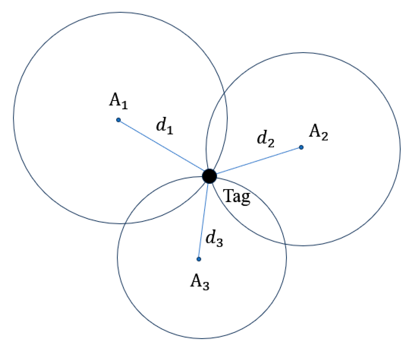
As a rule of thumb, a minimum of three anchor point ranges is the requisite for calculating tag coordinates. The geometric interplay between the anchor point and the tag is visually represented in Figure 1.
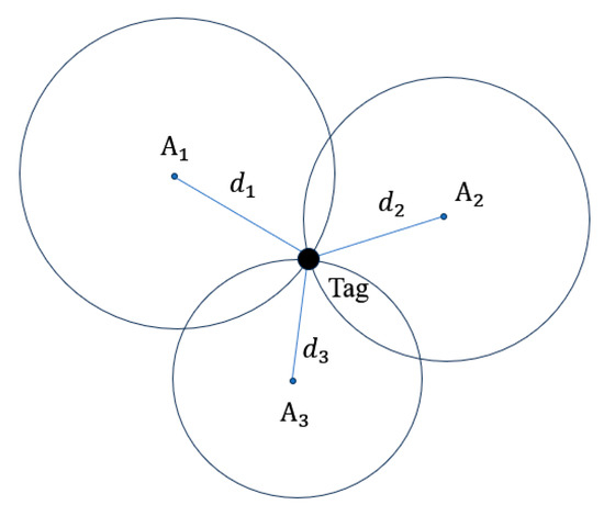
Figure 1.
Placement of anchors and tag.
In Figure 1, denotes three stationary anchor points, each characterised by coordinates Meanwhile, represent the respective range measurements between the corresponding anchor points and the tag. The point of intersection among the three circles establishes the tag’s position, defined by coordinates (x,y). This geometric correlation is succinctly encapsulated by Equation (2) [34].
In an ideal scenario, the circles would converge at a point. However, in real-world settings, the influence of noise on the ranging values results in an intersection region. Consequently, an optimal solution is imperative to ascertain the tag’s coordinates. The prevalent approach is the employment of the Least Squares (LS) method. Equation (2) is further elaborated upon and presented in matrix form, as in Equations (3) and (4).
The tag coordinates can be obtained by the LS method:
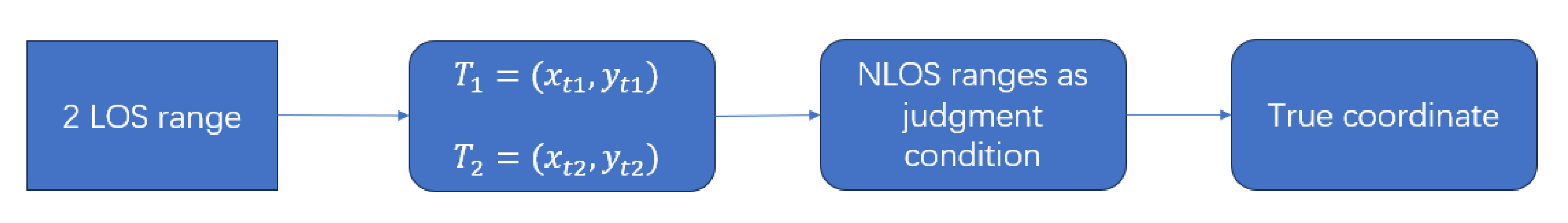
In the experimental setting of this study, certain anchor points’ range measurements are substantially impacted by NLOS conditions. Consequently, this paper employs a localisation algorithm incorporating a conditional judgment to achieve tag localisation, even when only two LOS anchors are available. The flowchart of the method is shown in Figure 2.
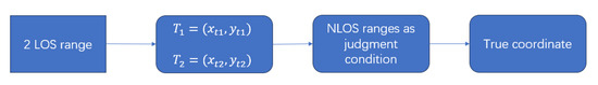
Figure 2.
Flowchart of the algorithm for the 2 LOS ranging values.
Due to the LOS conditions, UWB ranging exhibits a high degree of accuracy, with the impact of ambient noise resulting in ranging errors within 10 cm. This precision allows for the computation of coordinates for the two points of intersection using the range measurements from the two LOS anchor points. While the range values from the NLOS-affected anchor points may not be directly employed for tag localisation, they serve as a criterion to discern the actual coordinates of the tag from the two potential intersection points. This approach serves to enhance the accuracy of UWB positioning in NLOS environments to a significant extent.
2.2. Odometer
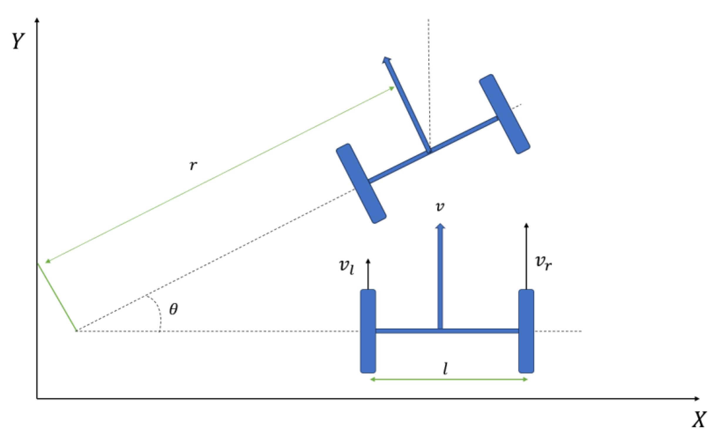
This paper employs the two-wheel differential model [35] to elucidate the robot’s locomotion in the context of odometer-based positioning. Within this model, effective control over the robot’s motion can be achieved by regulating the speeds of the wheeled robot’s left and right driving wheels.
In the Figure 3, and denote the linear velocities of the left and right driving wheels, respectively. represents the distance between the two wheels, r represents the turning radius, and θ signifies the turning angle. Based on this model, the ensuing equation can be derived.
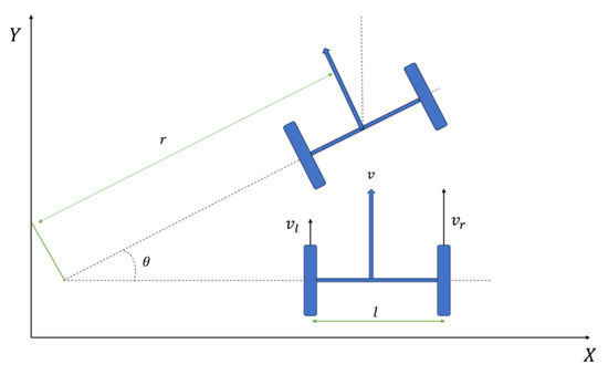
Figure 3.
Two-wheel differential motion model.
Linear velocity and angular velocity at the centre of the robot:
Turning radius:
When the sampling frequency is , the odometer data can be converted to the robot coordinates by the differential method (Equations (9)–(11)):
Wang et al. [36] categorised wheeled odometer errors into two primary classes. The first category encompasses systematic errors from hardware characteristics such as wheel diameter, wheelbase, and drive motor. These errors accumulate over time and contribute to positioning drift. The second category encompasses random errors, such as wheel slip and uneven terrain. Experimental design measures were taken to minimise these random errors as much as possible.
2.3. Methodology
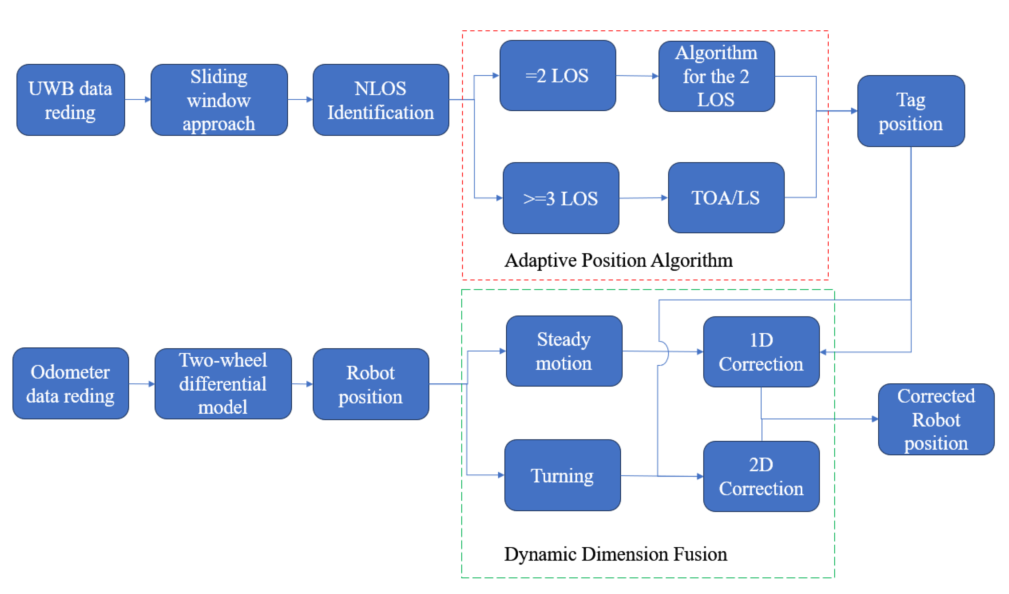
This section explains an indoor localisation method based on the fusion of odometry and UWB technology, as shown in Figure 4.
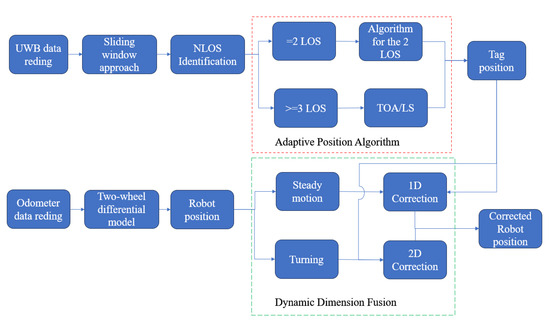
Figure 4.
Flowchart of the fusion algorithm.
The UWB system comprises four stationary anchors with predetermined coordinates and a tag with unknown coordinates. Ranging is executed utilising the Two Way Ranging (TWR) method, which circumvents the necessity for synchronised clocks between the anchors and the tag. This methodology mitigates the impact of the clock-drift error on the obtained ranging values [37]. After obtaining distance measurements between the four anchors and the tag, this paper implements the sliding window approach introduced in our prior research [38] to ascertain potential NLOS effects on the ranging values. The fundamental principle of this method is predicated on the premise that significant jumps in ranging measurements manifest when NLOS errors occur. By statistically analysing the variance of differences in a set of contiguous ranging values, when the variance of this set surpasses a specified threshold as the evaluation window slides over time, it is deduced that the ranging measurement at that specific instance is influenced by NLOS conditions, as delineated in Equations (12) and (13) [38]. The window size is an empirical value for UWB systems, and in this experiment, the best results were obtained with a window size of 50. Subsequently, the adaptive localisation algorithm outlined in the preceding section to derive optimised tag coordinates, considering variations in the number of LOS anchors.
In the above equation, represents the range value at the moment n, represents the difference between the range value at the moment n and the previous moment. If the window size is k, the variance of K consecutive differences versus a threshold can determine whether NLOS is present, as shown in Equation (13).
The fusion system employs a loosely coupled methodology. Specifically, this paper introduces a one-dimensional correction to the odometry in the direction perpendicular to the heading, leveraging optimisedUWB localisation data when the robot exhibits smooth motion characteristics (i.e., high linear velocity and low angular velocity). This correction effectively alleviates accumulated errors in the robot’s heading. Conversely, during cornering manoeuvres (characterised by low linear velocity and high angular velocity), a two-dimensional correction is applied to both the heading and total distance measured by the odometer, utilising UWB-derived coordinates. This two-dimensional correction addresses cumulative errors in the direction of motion and mitigates discrepancies in distance measurements by accounting for the relationship between actual motion distance and odometer readings. Through this approach, the fusion system significantly rectifies cumulative odometer errors.
This method is particularly well suited for practical applications compared to the traditional Zero Velocity Update (ZUPT) method [39]. ZUPT corrects errors during complete stationary phases, both actively and passively. Frequent active stationarity can diminish overall system efficiency and escalate collision risks and system complexity in multi-robot environments. On the other hand, passive stationarity often arises due to obstacles, such as passing pedestrians. These obstacles may influence the UWB system in such scenarios, leading to potential NLOS errors and highly inaccurate correction outcomes. This Dynamic Dimension Fusion scheme proposed in this paper furnishes a more precise localisation for the robot without disrupting the overall system operation.
3. Experiment and Results
3.1. Experimental Environments and Equipment
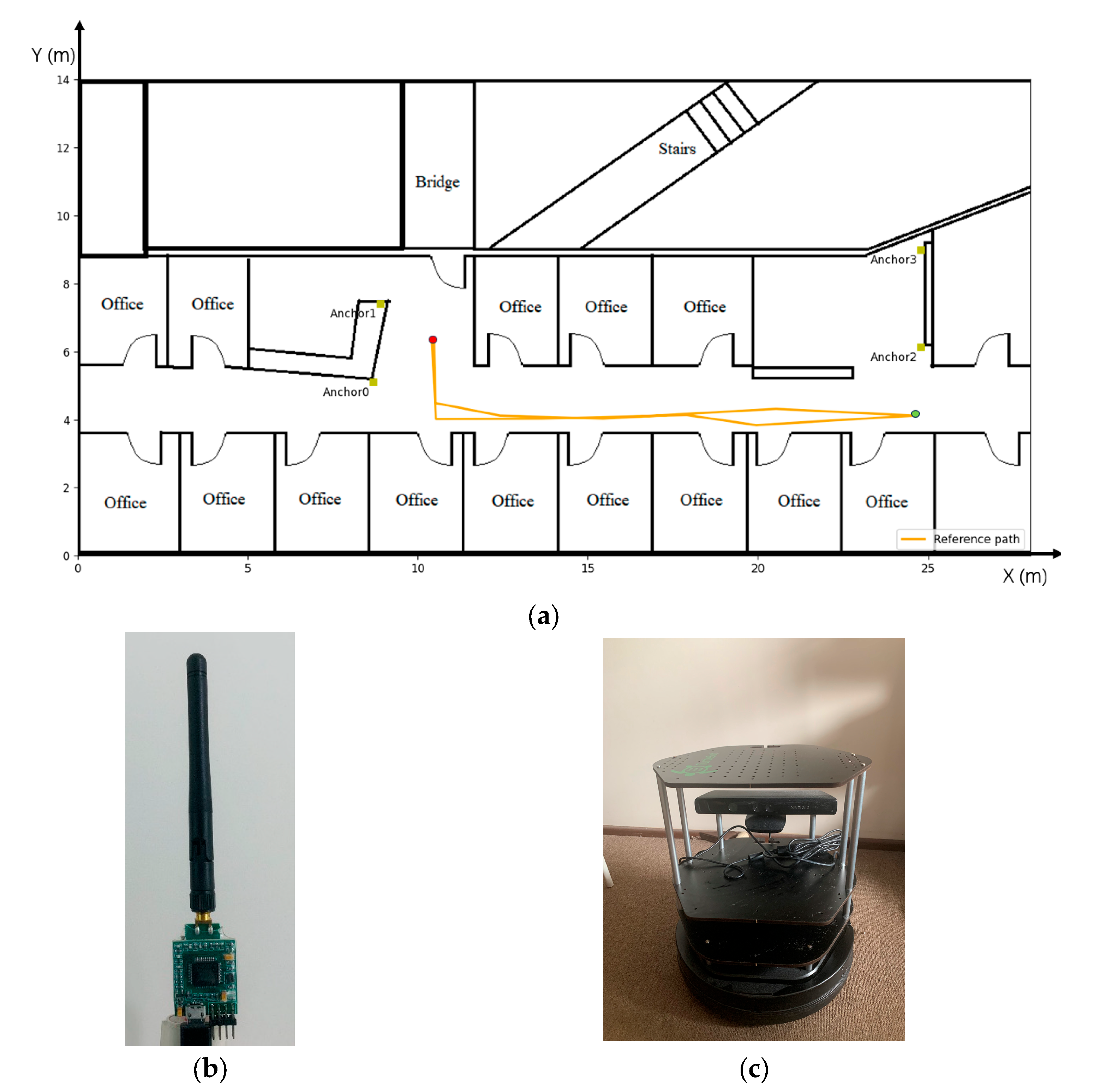
The experiment was conducted on the 11th floor of Building 11 at the University of Technology Sydney. The floor plan of the experimental area is shown in Figure 5a, and the map scale is in meters. The yellow squares denote the positions of the four UWB anchors. Specifically, the coordinates of Anchors 0, 1, 2, and 3 are (8.7, 5.1, 1.87), (8.91, 7.4, 1.87), (24.8, 6.13, 1.87), and (24.8, 8.99, 1.87), respectively. The area of the experiment is on the right side of the map in a corridor of length 15 m. The reference path of the robot is shown by the solid orange line in Figure 5a, while the red dots mark the start and end points of the robot’s trajectory, and the green dots indicate the turning point. Throughout the experiment, the turtlebot2 commences from the initial point, traverses the designated path up to the turning point, and returns to the endpoint. The UWB tag is affixed to the turtlebot2 and moves synchronously with it. Notably, obstacles such as walls and cabinets within the mapped environment significantly influence the UWB system, often resulting in pronounced NLOS errors during the UWB system’s operation.
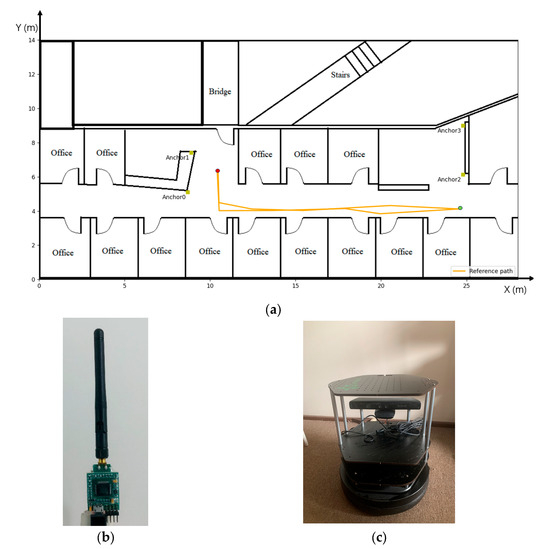
Figure 5.
Experiment design: (a) maps and reference path; (b) UWB; and (c) turtlebot2.
The UWB chips used for the UWB anchors and tags in the experiments (Figure 5b) are the DW1000 manufactured by DECAWAVE. This chip is characterised by its compact form factor, precise distance measurement capabilities, and cost-effectiveness [23]. It has garnered widespread adoption in both industrial and research applications [40,41,42]. Under LOS conditions, the UWB system exhibits a range error of less than 10 cm in the experiments, with a sampling frequency of 3 Hz.
The odometer employed is a wheel-type odometer sourced from the turtlebot2 platform (as shown in Figure 5c), operating at a sampling frequency of 20 Hz. The experimental environment features a flat carpeted surface with a high coefficient of friction, which effectively mitigates the impact of wheel slippage and uneven terrain on the odometers. Even if occasional slippage affects the accuracy of the odometer, the UWB is unaffected, and the absolute position provided by the UWB can still be used to correct the odometer to ensure system accuracy.
3.2. Experimental Results
This section is primarily dedicated to the analysis of the experimental results. It involves two main facets. Firstly, a comparative evaluation of the positioning outcomes is conducted before and after the optimisation of the UWB system. Secondly, the fusion of the optimisation UWB results with odometer position results are carried out using two distinct algorithms, DDF and UKF. The positioning accuracy attained through both fusion methodologies will be compared and presented.
The red trajectories depicted in Figure 6 were computed from the uncorrected ranging values, encompassing all NLOS errors and associated noise. These trajectories vividly demonstrate the significant adverse impact of NLOS errors on the UWB system’s positioning accuracy. Especially on the left and right sides of the trajectory, the blocked UWB signals cannot penetrate the multi-layer walls, and the ranging values contain large NLOS errors due to multipath effects. The maximum positioning error exceeds 16 m, with an RMSE of 1.851 m, rendering these results unequivocally unacceptable for UWB-based positioning.
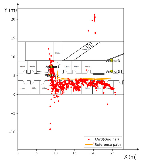
Figure 6.
UWB positioning results under the influence of NLOS.
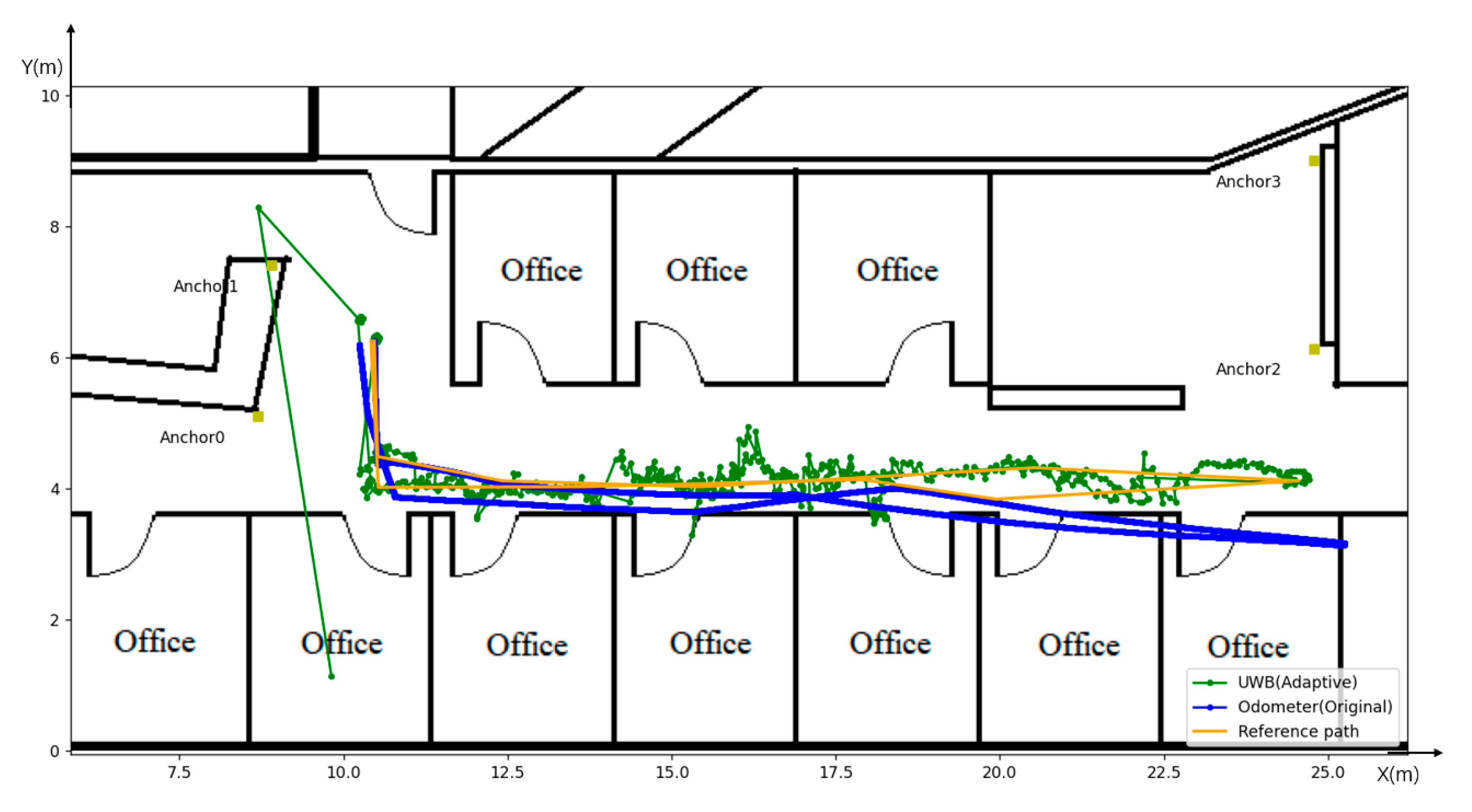
Upon application of the adaptive positioning algorithm, as evidenced by the green trajectories in Figure 7, notable improvements in accuracy are observed, even though some positioning points still exhibit considerable deviations. This discrepancy may arise from the inherent challenge of achieving absolute accuracy in NLOS identification. As observed in the trajectory, the tag establishes communication with three LOS anchors near the left and right turning points, ensuring a positioning accuracy consistent with the reference path. However, when navigating through the central corridor, the tag can only communicate with two LOS anchors, and the extended length of the corridor introduces a degree of multipath effect, causing some fluctuation in the calculated positioning points. The optimisedUWB positioning system yields a maximum positioning error of 2.968 m, with mean and RMSE errors of 0.127 m and 0.16 m, respectively.
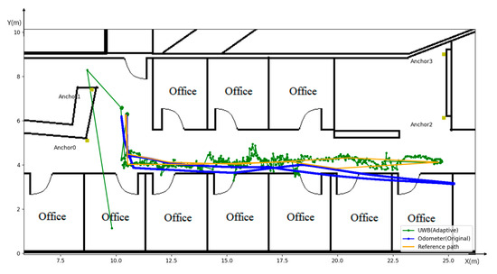
Figure 7.
UWB positioning results after the adaptive position algorithm.
In contrast, the blue trajectory in Figure 7 originates from the raw data obtained from the odometer. Comparative analysis with the reference path underscores the initial commendable accuracy of the odometer. However, over a duration of operation, there is a progressive accumulation of errors leading to a gradual divergence in the direction of motion. This deviation peaks at the rightmost inflexion point. Additionally, it is discernible that the odometer’s distance measurement exceeds the actual distance at this inflexion point, an outcome attributed to accumulated systematic errors.
The data from these two sensors will be fused by the proposed DDF and the traditional UKF, and the results are shown as follows.
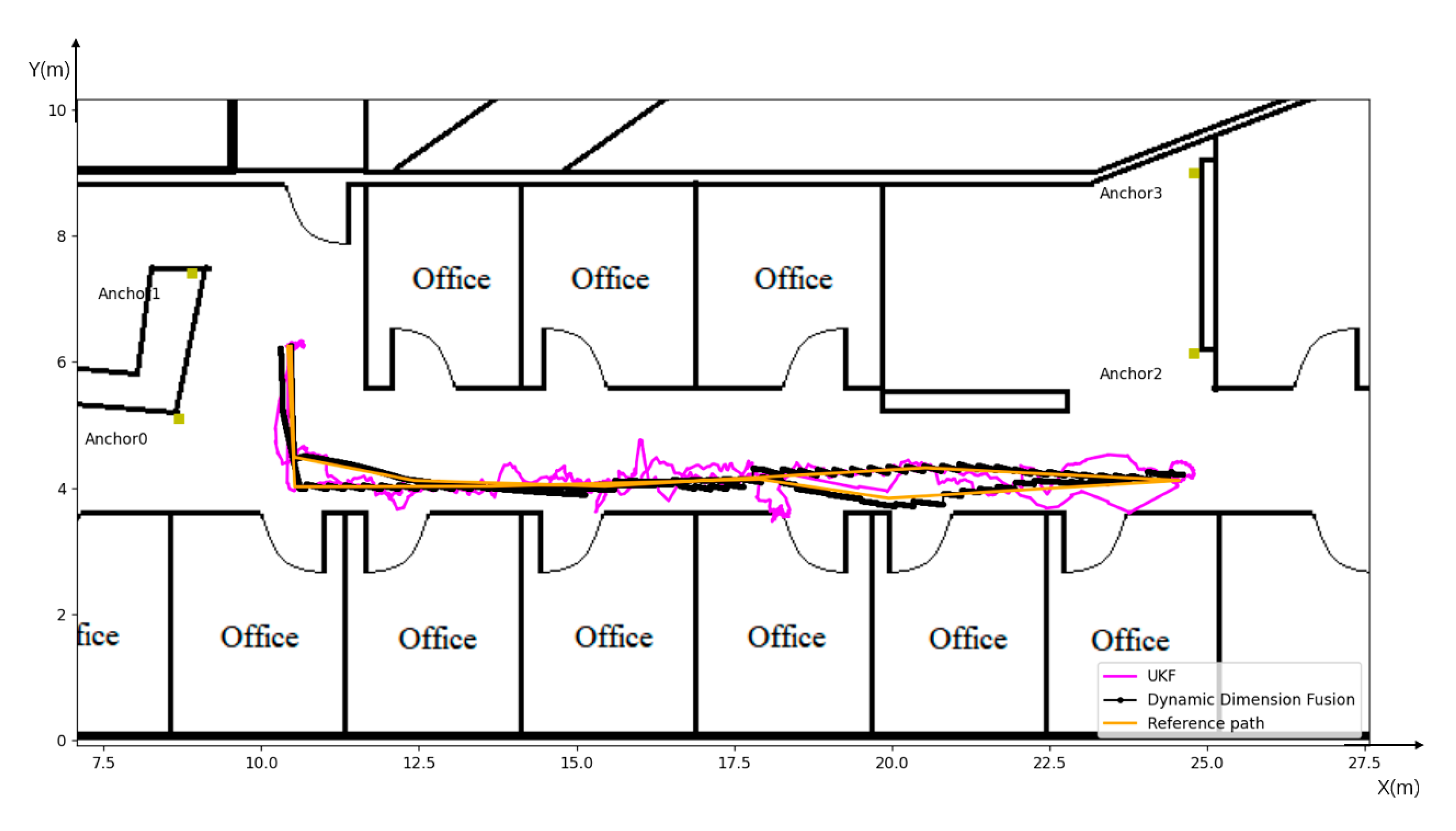
The comparison between the localisation results of the proposed DDF method (indicated by the black line) and the UKF approach (represented by the magenta line) is depicted in Figure 8. Notably, UKF stands out as a robust multi-sensor fusion algorithm that characterises the probability distribution of state variables through a set of sigma points. This technique sidesteps the error introduced by the Extended Kalman Filter (EKF) due to linearisation. While UKF entails higher computational demands, it is comparatively more straightforward to implement than the Jacobi matrix of EKF.
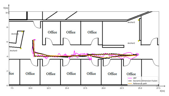
Figure 8.
Results of Dynamic Dimension Fusion and UKF.
The trajectories illustrated in Figure 8 and the data tabulated in Table 1 demonstrate that post-UKF fusion, the maximum positioning error is reduced to 0.677 m. Both the mean error and RMSE are substantially diminished to approximately 12 cm. This represents a notable enhancement in the accuracy of the initial odometer input and the optimisedUWB system.

Table 1.
Position errors.
The black trajectory in the figure portrays the motion path generated by the proposed DDF approach. The maximum speed of turtlebot2 on this material was measured to be 0.2 m per second in the experiments. Accordingly, when the linear velocity surpasses 0.15 m per second, and the absolute value of the angular velocity is less than 0.03 radians per second, a one-dimensional heading correction is applied to the odometer.
Furthermore, when the linear velocity falls below 0.1 m per second, and the absolute value of the angular velocity exceeds 0.65 radians per second, the odometer undergoes correction in two dimensions. This intervention yields a trajectory that closely aligns with the reference path. The data in Table 1 corroborate the efficacy of this approach, showcasing that the maximal error post-DDF fusion is reduced to 0.17 m. Both the mean error and RMSE have been reduced to under 5 cm. Consequently, the proposed DDF method surpasses UKF in terms of positioning accuracy.
4. Discussion
The following Table 2 summarises the comparison of the positioning accuracy of different sensors and UWB fusion, from which it can be seen that the best positioning accuracy is obtained from the paper [43]. However, the experimental environment is in the ideal LOS environment. The paper [28] shows that in the LOS environment, only using UWB can achieve high positioning accuracy with an RMSE equal to 4.66 cm. However, once the UWB has NLOS errors, even in a weak NLOS environment, the overall positioning accuracy of the fused system will be seriously affected, such as in the papers [24,27], where the RMSE exceeds 20 cm. The result of [30] achieves an RMSE of 5 cm in a weak NLOS environment but using moresensors, including the expensive LiDAR.
Table 2.
Comparison with other methods.
Therefore, in comparison with these papers, our proposed method uses only two sensors, UWB and odometer, and achieves an accuracy of NLOS equal to 0.042 m in a harsh NLOS environment, which is an excellent performance.
In the initial experimental findings, as depicted in Figure 6, it becomes evident that the precision of the UWB system’s positioning capability experiences a substantial decline when subjected to NLOS errors. This renders the system incapable of furnishing accurate positional information. While many approaches have been postulated to alleviate these NLOS errors, our experiments indicate that the most favourable positioning accuracy is achieved when ranges containing NLOS errors are straightforwardly omitted. This optimization arises from imperfections in the algorithms designed to detect and mitigate NLOS errors within the UWB system exclusively.
It’s crucial to recognize the limitations of the approach presented in this paper. First and foremost, the effectiveness of this method relies on having at least two LOS ranges. When only a single LOS anchor point is available, the UWB system struggles to calculate tag coordinates independently, making it unsuitable for the strategy described in this document. Additionally, the paper’s methodology primarily focuses on accurately determining the 2D coordinates of the tag. Comprehensive measurements for the tag’s three-dimensional coordinates will be a subject of future research. Lastly, due to the constraints of our testing environment, the placement of UWB anchor points was not optimal, affecting the precision of the UWB system’s positioning data. Furthermore, this research employs a loosely coupled fusion method that requires both the UWB and odometer systems to provide the location information of the tag. If the UWB system encounters errors that are difficult to recognise and ameliorate, especially in harsh environmental conditions, the inability to provide the coordinates of the tag results in the fused system’s positional accuracy being significantly compromised. Consequently, as part of forthcoming research endeavours, the research plan intends to transition towards a tightly coupled integration method. This will incorporate an RGB-D camera to enable real-time mapping, obstacle recognition, and path planning.
5. Conclusions
This paper introduces a fusion scheme for loosely coupling the UWB positioning system and the odometer, particularly in environments strongly influenced by NLOS conditions. The UWB system’s performance is notably compromised in such challenging conditions, while the odometer’s accuracy gradually diminishes over prolonged operation due to cumulative errors. This paper applies an optimisedUWB localisation approach to address these challenges, leveraging previously studied NLOS identification techniques based on sliding windows. Furthermore, a novel DDF method was proposed for integrating the optimisedUWB localisation data with odometry, employing a loose-coupling fusion strategy. Notably, this method obviates the need for the robot to be actively or passively stationary for odometer calibration, and the calibration process exerts no influence on the robot’s motion. This enhancement significantly bolsters system efficiency and renders it more conducive for practical applications. The feasibility and accuracy of this fusion scheme are confirmed by experiments conducted in a real environment. The experimental results manifest an impressive RMSE and average error of fewer than 5 cm for robot positioning. This performance surpasses the positioning accuracy of the odometer and the optimisedUWB system and outperforms the fusion accuracy achieved through the UKF.
Author Contributions
Conceptualization, A.L. and X.K.; methodology, A.L. and J.W.; software, A.L.; validation, A.L.; formal analysis, A.L.; investigation, A.L.; resources, A.L.; data curation, A.L.; writing—original draft preparation, A.L.; writing—review and editing, A.L., J.W. and S.L.; visualization, A.L.; supervision, J.W. and X.K.; project administration, A.L. and J.W.; funding acquisition, A.L. All authors have read and agreed to the published version of the manuscript.
Funding
This research received no external funding.
Data Availability Statement
Not applicable.
Conflicts of Interest
The authors declare no conflict of interest.
References
- Zhang, Q.; Niu, X.; Shi, C. Impact assessment of various IMU error sources on the relative accuracy of the GNSS/INS systems. IEEE Sens. J. 2020, 20, 5026–5038. [Google Scholar] [CrossRef]
- Hu, J.; Hu, C. A WiFi Indoor Location Tracking Algorithm Based on Improved Weighted K Nearest Neighbors and Kalman Filter. IEEE Access 2023, 11, 32907–32918. [Google Scholar] [CrossRef]
- Babalola, O.P.; Balyan, V. WiFi fingerprinting indoor localization based on dynamic mode decomposition feature selection with hidden Markov model. Sensors 2021, 21, 6778. [Google Scholar] [CrossRef]
- Jondhale, S.R.; Mohan, V.; Sharma, B.B.; Lloret, J.; Athawale, S.V. Support vector regression for mobile target localization in indoor environments. Sensors 2022, 22, 358. [Google Scholar] [CrossRef]
- Newman, N. Apple iBeacon technology briefing. J. Direct Data Digit. Mark. Pract. 2014, 15, 222–225. [Google Scholar] [CrossRef]
- Aranda, F.J.; Parralejo, F.; Álvarez, F.J.; Paredes, J.A. Performance analysis of fingerprinting indoor positioning methods with BLE. Expert Syst. Appl. 2022, 202, 117095. [Google Scholar] [CrossRef]
- Qayyum, U.; Kim, J. Depth-camera-aided inertial navigation utilizing directional constraints. Sensors 2021, 21, 5913. [Google Scholar] [CrossRef]
- Damodaran, D.; Mozaffari, S.; Alirezaee, S.; Ahamed, M.J. Experimental Analysis of the Behavior of Mirror-like Objects in LiDAR-Based Robot Navigation. Appl. Sci. 2023, 13, 2908. [Google Scholar] [CrossRef]
- Sharma, S.; Deka, K.; Mandloi, M. Deep learning noncoherent UWB receiver design. IEEE Sens. Lett. 2021, 5, 7002104. [Google Scholar] [CrossRef]
- Zhou, N.; Lau, L.; Bai, R.; Moore, T. Novel prior position determination approaches in particle filter for ultra wideband (UWB)-based indoor positioning. Navig. J. Inst. Navig. 2021, 68, 277–292. [Google Scholar] [CrossRef]
- Zhang, H.; Wang, Q.; Xu, J.; Li, Z.; Yang, Y. Time delay characteristics analysis of UWB diffraction propagation in indoor NLOS environment. IEEE Commun. Lett. 2022, 27, 1889–1893. [Google Scholar] [CrossRef]
- Li, J.; Gao, T.; Wang, X.; Guo, W.; Bai, D. Study on the UWB location algorithm in the NLOS environment. J. Phys. Conf. Ser. 2022, 2400, 012043. [Google Scholar] [CrossRef]
- Chen, C.; Huang, Z.; Wang, J.; Yuan, L.; Bao, J.; Chen, Z. Channel-quality-evaluation-based anchor node selection for UWB indoor positioning. Electronics 2022, 11, 436. [Google Scholar] [CrossRef]
- Cully, W.P.; Cotton, S.L.; Scanlon, W.G.; McQuiston, J. Body shadowing mitigation using differentiated LOS/NLOS channel models for RSSI-based Monte Carlo personnel localization. In Proceedings of the 2012 IEEE Wireless Communications and Networking Conference (WCNC), Paris, France, 1–4 April 2012; pp. 694–698. [Google Scholar]
- Ferreira, A.G.; Fernandes, D.; Branco, S.; Catarino, A.P.; Monteiro, J.L. Feature selection for real-time NLOS identification and mitigation for body-mounted UWB transceivers. IEEE Trans. Instrum. Meas. 2021, 70, 5502310. [Google Scholar] [CrossRef]
- Moro, G.; Di Luca, F.; Dardari, D.; Frisoni, G. Human Being Detection from UWB NLOS Signals: Accuracy and Generality of Advanced Machine Learning Models. Sensors 2022, 22, 1656. [Google Scholar] [CrossRef]
- Bharadwaj, R.; Alomainy, A.; Koul, S.K. Experimental investigation of body-centric indoor localization using compact wearable antennas and machine learning algorithms. IEEE Trans. Antennas Propag. 2021, 70, 1344–1354. [Google Scholar] [CrossRef]
- Cui, Z.; Gao, Y.; Hu, J.; Tian, S.; Cheng, J. LOS/NLOS identification for indoor UWB positioning based on Morlet wavelet transform and convolutional neural networks. IEEE Commun. Lett. 2020, 25, 879–882. [Google Scholar] [CrossRef]
- Musa, A.; Nugraha, G.D.; Han, H.; Choi, D.; Seo, S.; Kim, J. A decision tree-based NLOS detection method for the UWB indoor location tracking accuracy improvement. Int. J. Commun. Syst. 2019, 32, e3997. [Google Scholar] [CrossRef]
- Kim, D.-H.; Farhad, A.; Pyun, J.-Y. UWB positioning system based on LSTM classification with mitigated NLOS effects. IEEE Internet Things J. 2022, 10, 1822–1835. [Google Scholar] [CrossRef]
- Dineva, K.; Atanasova, T. Systematic look at machine learning algorithms—Advantages, disadvantages and practical applications. Int. Multidiscip. Sci. GeoConf. SGEM 2020, 20, 317–324. [Google Scholar]
- Feng, D.; Peng, J.; Zhuang, Y.; Guo, C.; Zhang, T.; Chu, Y.; Zhou, X.; Xia, X.-G. An Adaptive IMU/UWB Fusion Method for NLOS Indoor Positioning and Navigation. IEEE Internet Things J. 2023, 10, 11414–11428. [Google Scholar] [CrossRef]
- Ali, R.; Liu, R.; Nayyar, A.; Qureshi, B.; Cao, Z. Tightly coupling fusion of UWB ranging and IMU pedestrian dead reckoning for indoor localization. IEEE Access 2021, 9, 164206–164222. [Google Scholar] [CrossRef]
- Peng, P.; Yu, C.; Xia, Q.; Zheng, Z.; Zhao, K.; Chen, W. An indoor positioning method based on UWB and visual fusion. Sensors 2022, 22, 1394. [Google Scholar] [CrossRef] [PubMed]
- Sun, Y.; Guan, L.; Chang, Z.; Li, C.; Gao, Y. Design of a low-cost indoor navigation system for food delivery robot based on multi-sensor information fusion. Sensors 2019, 19, 4980. [Google Scholar] [CrossRef] [PubMed]
- Chen, Z.; Xu, A.; Sui, X.; Hao, Y.; Zhang, C.; Shi, Z. NLOS Identification-and Correction-Focused Fusion of UWB and LiDAR-SLAM Based on Factor Graph Optimization for High-Precision Positioning with Reduced Drift. Remote Sens. 2022, 14, 4258. [Google Scholar] [CrossRef]
- Kim, D.-H.; Pyun, J.-Y. NLOS identification based UWB and PDR hybrid positioning system. IEEE Access 2021, 9, 102917–102929. [Google Scholar] [CrossRef]
- Li, J.; Gao, T.; Wang, X.; Bai, D.; Guo, W. The IMU/UWB/odometer fusion positioning algorithm based on EKF. J. Phys. Conf. Ser. 2022, 2369, 012092. [Google Scholar] [CrossRef]
- Venkata Krishnaveni, B.; Reddy, S. Indoor Tracking by Adding IMU and UWB using Unscented Kalman Filter. Wirel. Pers. Commun. 2022, 123, 3575–3596. [Google Scholar] [CrossRef]
- Jia, L.; Wang, Y.; Ma, L.; He, Z.; Li, Z.; Cui, Y. Integrated Positioning System of Kiwifruit Orchard Mobile Robot Based on UWB/LiDAR/ODOM. Sensors 2023, 23, 7570. [Google Scholar] [CrossRef]
- Tang, C.; He, C.; Dou, L. An IMU/ODM/UWB joint localization system based on modified cubature kalman filtering. Sensors 2021, 21, 4823. [Google Scholar] [CrossRef]
- Zhou, B.; Fang, H.; Xu, J. UWB-IMU-odometer fusion localization scheme: Observability analysis and experiments. IEEE Sens. J. 2022, 23, 2550–2564. [Google Scholar] [CrossRef]
- Naheem, K.; Kim, M.S. A low-cost foot-placed UWB and IMU fusion-based indoor pedestrian tracking system for IoT applications. Sensors 2022, 22, 8160. [Google Scholar] [CrossRef] [PubMed]
- Liu, Y. UWB ranging error analysis based on TOA mode. J. Phys. Conf. Ser. 2021, 1939, 012124. [Google Scholar] [CrossRef]
- Mújica-Vargas, D.; Vela-Rincón, V.; Luna-Álvarez, A.; Rendón-Castro, A.; Matuz-Cruz, M.; Rubio, J. Navigation of a Differential Wheeled Robot Based on a Type-2 Fuzzy Inference Tree. Machines 2022, 10, 660. [Google Scholar] [CrossRef]
- Wang, Z.; Tan, J.; Sun, Z. Error factor and mathematical model of positioning with odometer wheel. Adv. Mech. Eng. 2015, 7, 305981. [Google Scholar] [CrossRef]
- Tiemann, J.; Koring, L.; Gorczak, P.; Wietfeld, C. Improving the robustness of control-grade ultra-wideband localization. IFAC-Pap. 2018, 51, 103–108. [Google Scholar] [CrossRef]
- Liu, A.; Lin, S.; Wang, J.; Kong, X. A Succinct Method for Non-Line-of-Sight Mitigation for Ultra-Wideband Indoor Positioning System. Sensors 2022, 22, 8247. [Google Scholar] [CrossRef]
- Gui, L.; Zeng, C.; Dauchert, S.; Luo, J.; Wang, X. A ZUPT Aided Initialization Procedure for Tightly-coupled Lidar Inertial Odometry based SLAM System. J. Intell. Robot. Syst. 2023, 108, 40. [Google Scholar] [CrossRef]
- Umek, A.; Kos, A. Validation of UWB positioning systems for player tracking in tennis. Pers. Ubiquitous Comput. 2022, 26, 1023–1033. [Google Scholar] [CrossRef]
- Wei, Z.; Jiang, R.; Wei, X.; Cheng, Y.-A.; Cheng, L.; Wang, C. Novel indoor positioning system based on ultra-wide bandwidth. Vis. Comput. Ind. Biomed. Art 2020, 3, 1. [Google Scholar] [CrossRef]
- Polonelli, T.; Qin, Y.; Yeatman, E.M.; Benini, L.; Boyle, D. A flexible, low-power platform for UAV-based data collection from remote sensors. IEEE Access 2020, 8, 164775–164785. [Google Scholar] [CrossRef]
- Yao, H.; Wang, X.; Qi, H.; Liang, X. Tightly Coupled Indoor Positioning Using UWB/mmwave Radar/IMU. Int. Arch. Photogramm. Remote Sens. Spat. Inf. Sci. 2022, 46, 323–329. [Google Scholar] [CrossRef]

Disclaimer/Publisher’s Note: The statements, opinions and data contained in all publications are solely those of the individual author(s) and contributor(s) and not of MDPI and/or the editor(s). MDPI and/or the editor(s) disclaim responsibility for any injury to people or property resulting from any ideas, methods, instructions or products referred to in the content. |
© 2023 by the authors. Licensee MDPI, Basel, Switzerland. This article is an open access article distributed under the terms and conditions of the Creative Commons Attribution (CC BY) license (https://creativecommons.org/licenses/by/4.0/).