Abstract
For integrated pose control of six-degree-of-freedom (6-DOF) leader–following spacecraft formations, the coupled relative pose between two spacecraft is described by a unified model in the framework of twistors, based on which a finite-time control law is devised for the 6-DOF dynamic system. Firstly, some necessary coordinate frames are defined, and then, relative 6-DOF dynamics of the follower spacecraft with respect to the desired frame are modeled by using twistors. Secondly, an integrated pose controller is designed for the 6-DOF formation that takes full advantage of homogeneous theory to guarantee finite-time stability. Finally, numerical simulations are carried out to validate the effectiveness of the proposed controller. Developing integrated 6-DOF formation control law based on twistors is more straightforward than conventional methods, and the finite-time algorithm achieves stronger robustness than asymptotic ones.
1. Introduction
Due to the increasingly demanding requirements of future space missions, space technology is encountering an increasing number of challenges as it progresses [1]. More and more attention is being paid to 6-DOF spacecraft formations because plenty of low-cost satellites are being sent to space to work cooperatively [2]. Ref. [3] researched the coordinated control of 6-DOF spacecraft formations with external disturbances and communication delays considered in the situation for which velocity is immeasurable. In Ref. [4], a coupled pose error dynamic model of 6-DOF spacecraft formations was established, based on which the authors devised a pose tracking law by employing the sliding mode control theory with an event-triggering strategy introduced to reduce the communication rate between the spacecraft. In Ref. [5], a fixed-time relative pose tracking controller with hysteretic quantized control input was devised for 6-DOF spacecraft formations, in which the fast terminal sliding mode control method was used in conjunction with an adaptive law. The proposed control scheme guaranteed fixed-time convergence of the closed-loop system in the presence of input quantization, uncertainties, and disturbances. Meanwhile, it lightened the communication burden and avoided the oscillations resulting from the logarithm quantizer.
In conventional methods for modeling spacecraft dynamics, translational motion and rotational motion are represented separately [6]. However, ignoring the coupling between translation and rotation may lead to nonnegligible errors in spacecraft formations [7]. Dual quaternions, which originate from Clifford algebra, can describe the translation and rotation of a rigid body simultaneously and briefly [8,9]. For the leader–following formation of two spacecraft, the relative pose of the spacecraft can be represented in a unified way by employing dual quaternions, which can simplify the design of the control law for 6-DOF formations [10]. Li et al. [11] investigated the coupled pose control of 6-DOF spacecraft motion using dual quaternions, and an event-triggered PI-like control algorithm with an active disturbance rejection strategy was proposed for pose tracking, which considers the separate time scale of the 6-DOF system and thus possesses a lower communication rate than that of controllers using a coupled-triggering strategy. A dual-quaternion-based extended Kalman filter was proposed first in Ref. [12] to estimate both the pose and (linear and angular) velocity of a spacecraft.
Another tool for uniformly describing the coupled pose motion is twistors, which were originally derived by applying the principles of geometric algebra [13,14]. Although dual quaternions can describe the translational and rotational motion of spacecraft in a unified way, dual-quaternion-based representation possesses redundant elements that may result in additional communication and computation burden. Further, a dual quaternion used to represent pose motion must be a unit quaternion, which is inconvenient in some aspects [13]. For example, it is difficult to apply an unscented Kalman filter to a dual-quaternion-represented system [15]. In Ref. [14], twistors, which are of six dimensions, were utilized to parameterize translational and rotational motion of elastically coupled rigid bodies. The definition of twistors has been given in the framework of geometric algebra as well. Ref. [13] presented a coupled relative pose dynamic model of spacecraft based on twistors and then designed an asymptotically stable PD-like controller. Zhang and Cai [16] used twistors to describe the pose motion of a spacecraft relative to an asteroid, and a collision-free pose control scheme for landing was proposed with the help of the artificial potential field (APF) technique. Ref. [17] further developed an adaptive 6-DOF saturated control algorithm for spacecraft landing on an asteroid on the basis of a twistor model. Similarly, the APF technique was introduced into the backstepping method to avoid collisions. Zhang and Li [18] devised a twistor-based control scheme for spacecraft formations considering the coupling between position and attitude dynamics and achieved finite-time stability by the application of the fast terminal sliding mode technique. In Ref. [19], the 6-DOF distributed control of a spacecraft formation near an asteroid was investigated in the framework of twistors to cope with position–attitude coupling. To overcome the numerical difficulty, scaled twistors were introduced into the relative dynamic model, and then the consensus theory was combined with the dynamic surface control method to derive a distributed control protocol.
Due to its fast response and strong robustness [20,21], finite-time control in the field of spacecraft control is becoming a hot research topic [22,23]. In Ref. [24], a non-linear quaternion-based finite-time control scheme with bounded control inputs was developed with the aid of homogeneous theory, and the unwinding phenomenon was avoided by selecting appropriate equilibria. Gui et al. [22] constructed a finite-time output feedback pose tracking control scheme for spacecraft based on dual quaternion representation, where a simple second-order filter was designed to provide the estimates of spacecraft velocity. In the control scheme, the homogeneous theory was employed to ensure finite-time stability, and the hybrid system theory was used to achieve global convergence. Ref. [25] presented a finite-time pose tracking algorithm without velocity measurements in the framework of dual quaternions. Likewise, the unavailable velocity was estimated by an observer, but the finite-time stability of the closed-loop system was guaranteed via the terminal sliding mode control theory. To avoid collisions in spacecraft formations, Zhang et al. [26] designed a finite-time controller for satellite formations by embedding an APF into the second-order sliding mode control method.
Though finite-time control of spacecraft has been extensively studied, twistor-based integrated position and attitude control, which possesses the advantages of both twistor representation and finite-time convergence, has not appeared (the approach in Ref. [18] is just practical finite-time stable). Therefore, investigating finite-time control of spacecraft formations in the framework of twistors will greatly promote the development of spacecraft formations. The existing challenges in representative works are summarized in Table 1. For integrated position and attitude control of 6-DOF spacecraft formations, a finite-time control law based on twistor representation is proposed to get rid of the normalization constraint and state dimension redundancy in order to improve the response speed and robustness.

Table 1.
Challenges in representative works on spacecraft control.
This paper presents a finite-time pose control law for leader–following spacecraft formations with the application of the homogeneous theory based on the coupled relative pose dynamic model described by twistors. First, the relative pose dynamics of spacecraft are represented by twistors to acquire integrated position and attitude motion equations. Then, a control law under the twistors framework is proposed with the aid of homogeneous theory, and the finite-time convergence of the closed-loop system is revealed through the homogeneous theory and Lyapunov stability theory. Next, case simulations are carried out to confirm the effectiveness of the devised control algorithm with necessary discussions and analysis presented. The advantages of the control law are clearly shown through comparisons. Finally, some conclusions are given to finalize this paper.
2. Preliminaries
Before proceeding to the main results, this section presents some critical mathematical preliminaries to ease the understanding of the proposed algorithm.
2.1. Definitions and Lemmas
Let for any and , where is the sign function. Clearly, the function is non-smooth and continuous if . Let and a vector , where . For any , define an operator as .
Definition 1
([28]). Assume the following system
where is continuous on an open neighborhood of the origin. For and any , if , is called a homogeneous function of degree with regard to . Then, the system (1) is homogeneous if is homogeneous.
Definition 2
([29]). Let denote a neighborhood of . If the system (1) is uniformly Lyapunov stable on Ξ and converges uniformly to the origin in finite time on Ξ, the origin is uniformly finite-time stable (UFTS).
Lemma 1
([30]). Assume the system represented by
where is a homogeneous continuous function of degree with regard to and meets the condition . It is assumed that the system asymptotically converges to the equilibrium . Then, the system (2) is uniformly locally finite-time stable with being its equilibrium if satisfies
The proof of Lemma 1 can be seen in [27]. As shown in [27], if the system (2) is disturbed by a small disturbance and , is still finite-time stable.
2.2. Coordinate Frame Definition and Twistor-Based Motion Equations
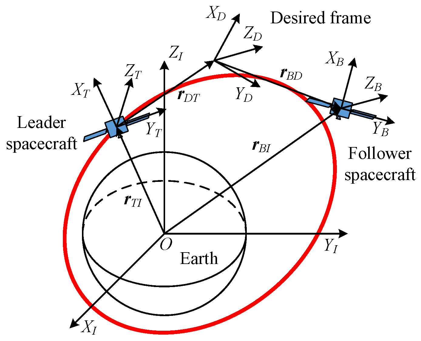
To facilitate describing the 6-DOF dynamics of spacecraft, some coordinate frames are defined as follows. The right-handed inertial coordinate frame is fixed in the inertial space and denoted by . The origin of the coordinate frame is the barycenter of the follower spacecraft, with the axes aligned with the principal axes of inertia to constitute a right-handed coordinate system. The desired pose of the follower spacecraft is described by the coordinate frame , which means that is the desired frame of . The right-handed frame is fixed with the leader spacecraft, the origin of which is located at the barycenter and the axes of which are aligned with its principal inertia axes. The relationship between these coordinate frames is illustrated in Figure 1.

Figure 1.
Relationship between the frames , , , and .
It is expected that the axes of coincide with the axes of . The pose of relative to described in the framework of dual quaternions is given by [31]
where and denote the set of quaternions and the set of quaternions with null scalar parts, respectively, is the quaternion that represents the attitude of relative to , is the displacement vector of (the origin of ) relative to (the origin of ) resolved in the coordinate system , and is the same vector resolved in . The term , satisfying and , is the dual unit. Thus, the twistor, which represents the pose of relative to , is expressed by the dual quaternion as [13,16]
where is the set of dual quaternions, is the unit dual quaternion, (the real part of ) are the Modified Rodrigues Parameters (MRPs) of the body-fixed frame relative to its desired frame , and the term is the dual part relying on the MRPs and the relative position vector. Hence, a twistor can also be regarded as dual MRPs [13]. Both and are the special quaternions with zero scalar parts, and the expressions of their vector parts are given by
with
where symbolizes the vector part of a quaternion; , , and extract the real part of a dual quaternion, vector part of a quaternion, and scalar part of a quaternion, respectively; and gives a skew-symmetric matrix that satisfies . The above equations show that a twistor comprises two quaternions whose scalar parts are zero, indicating that the pose is described by six parameters. Clearly, the dimension of twistors is less than that of dual quaternions. More information about twistors can be obtained from Refs. [13,14].
The relative pose motion is described by twistors as [13]
where , with and being the angular velocity vector and position vector, respectively, of with respect to resolved in . The expressions of and resemble that of and are omitted here for conciseness. According to the definition of twistors, and represent the same relative pose between frames. As shown in Ref. [13], when , is singular and is used instead of . The term denotes the dual inertia matrix, which is given by [16]
where is the inertial matrix of the follower spacecraft, and m is its mass. Then, the inversion of is
The dual force caused by gravity expressed in is defined as . The terms and represent the gravitational force vector and gravitational gradient torque vector resolved in . The term is the dual control force expressed as , where and are the control torque and force, respectively, resolved in .
3. Twistor-Based Finite-Time Control Law Design
For the convenience of twistor-based finite-time control law design using homogeneous theory, two functions of are given by
where is the set of twistors; denotes a twistor with all zero elements; ∘ represents circle multiplication between twistors; and are the matrices attained from multiplication of twistors, which satisfy [16,17,19]; the operation denotes the Euclidean norm; and . It can be proved that the two functions in Equations (14) and (15) are continuous. For , , , and , a twistor-based control scheme with finite-time stability is designated as
where means a swap operation of a twistor. The control goal is to stabilize the set (subscript omitted for convenience).
A Lyapunov function candidate with is selected as
where . satisfies and if and only if . The time derivative of is given by
Therefore, O is uniformly Lyapunov stable.
Equation (18) implies that exists and is finite, and therefore are uniformly bounded. Because and are set to be bounded, is uniformly bounded according to Equations (11) and (16). Thus, are uniformly continuous as a result. Then, the conclusion that and thus is obtained through Barbalat’s lemma [32]. Since both and are uniformly bounded and uniformly continuous and is a continuous function of , then is uniformly continuous with respect to time. Substituting Equation (16) into (11), it follows that is uniformly continuous due to the fact that all the terms involved are uniformly continuous. By using Barbalat’s lemma again, one can conclude that , and thus, , which implies that . Thus, we prove that O is UAS.
Note that Equations (19) and (20) take the same form as the system in (2). With the same Lyapunov function candidate as Equation (17), it can be proven by similar analysis that the set O possesses asymptotic stability for the system composed of Equations (19) and (20). Let with the dilation . For any , and , set , . Then, the following equations can be obtained readily by some simple operations:
According to Definition 1, the vector field has homogeneity of degree k with regard to the dilation . For and , we have
4. Simulations
The proposed method is simulated and analyzed in this section to verify its effectiveness. Further, the simulation results of the PD-like method in [13] are also shown for comparison. For the simulations of the above two methods, the total simulation time is 200 s and the time step is set to 0.01 s. Figure 2 describes how the simulation model is set up. The inertia matrix of the spacecraft is set to
with its mass being .
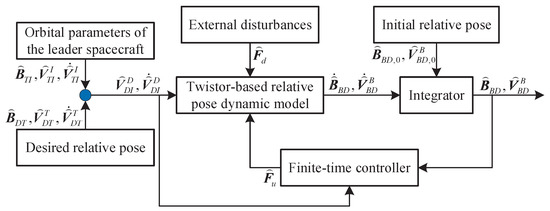
Figure 2.
Block diagram of the simulation.
The desired position vector of relative to expressed in is . The scenario is to keep stationary relative to , which means . Quaternion represents the desired attitude of relative to . The desired angular velocity of with respect to resolved in is . The initial position vector and velocity vector of relative to expressed in are and , respectively. The initial relative angular velocity of with regard to expressed in is , and the initial quaternion of relative to is . Table 2 displays the orbital parameters of the leader spacecraft. Assume that always coincides with the local vertical and local horizontal coordinate frame. External disturbances are given by
Table 2.
Orbital parameters of the leader spacecraft.
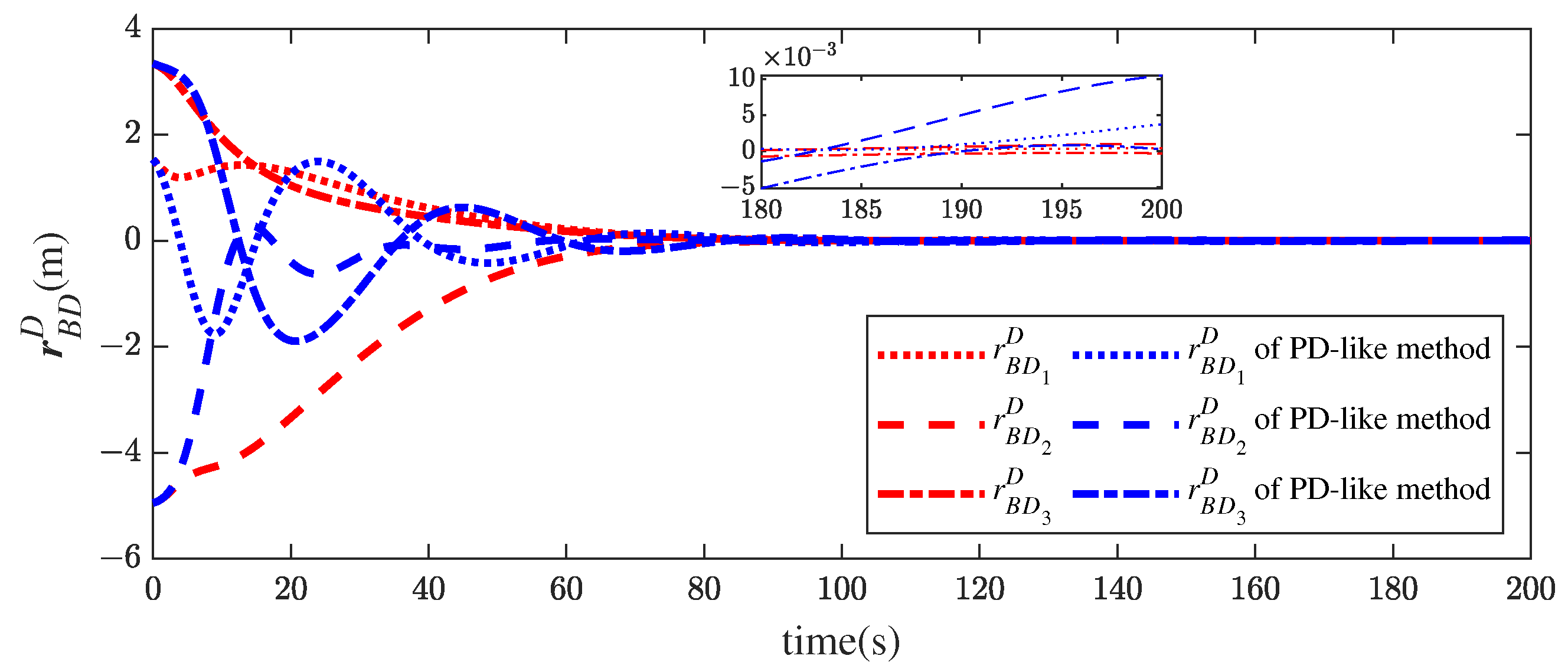
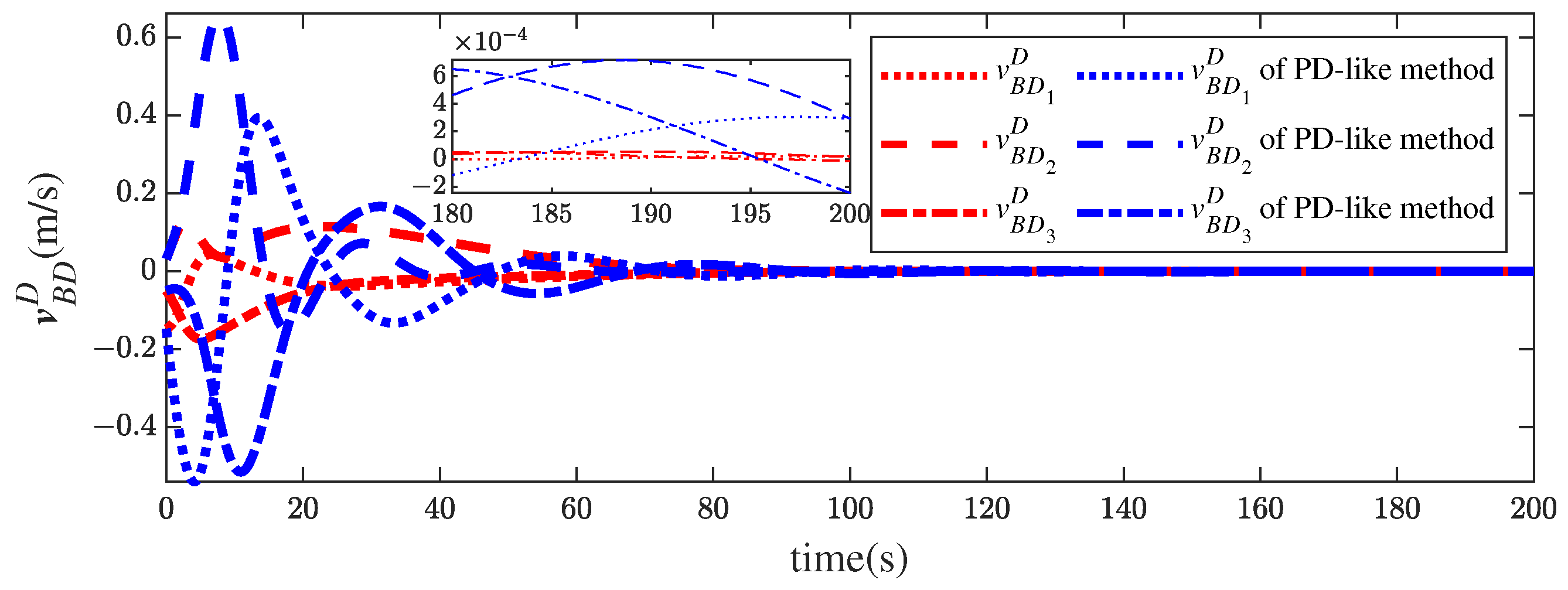
In Figure 3, the relative position vector histories of the follower spacecraft relative to the desired frame are given. It can be observed that the components of the position vector converge to the neighborhood of zero. The results imply that the follower spacecraft moves to its desired position and stays in the desired position. Figure 4 shows the time histories of the velocity vector of the follower spacecraft relative to the desired coordinate frame. The variations of the relative velocities are consistent with those of the corresponding position histories in Figure 3. Clearly, the convergence of the controller in this paper is smoother and the steady errors smaller than those of the control law in Ref. [13].
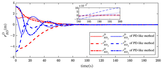
Figure 3.
Relative position histories of the proposed method and the PD-like method in [13].
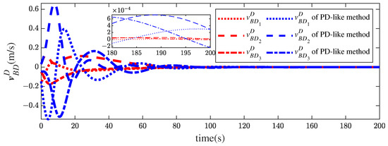
Figure 4.
Relative velocity histories of the proposed method and the PD-like method in [13].
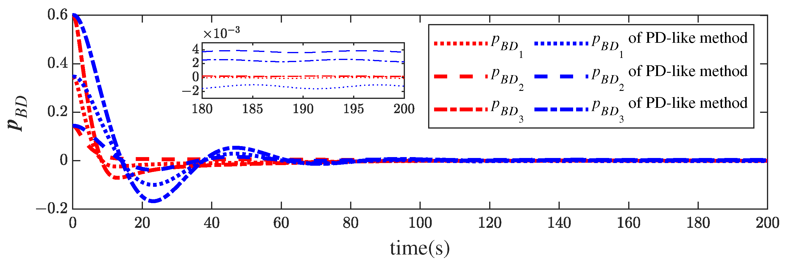
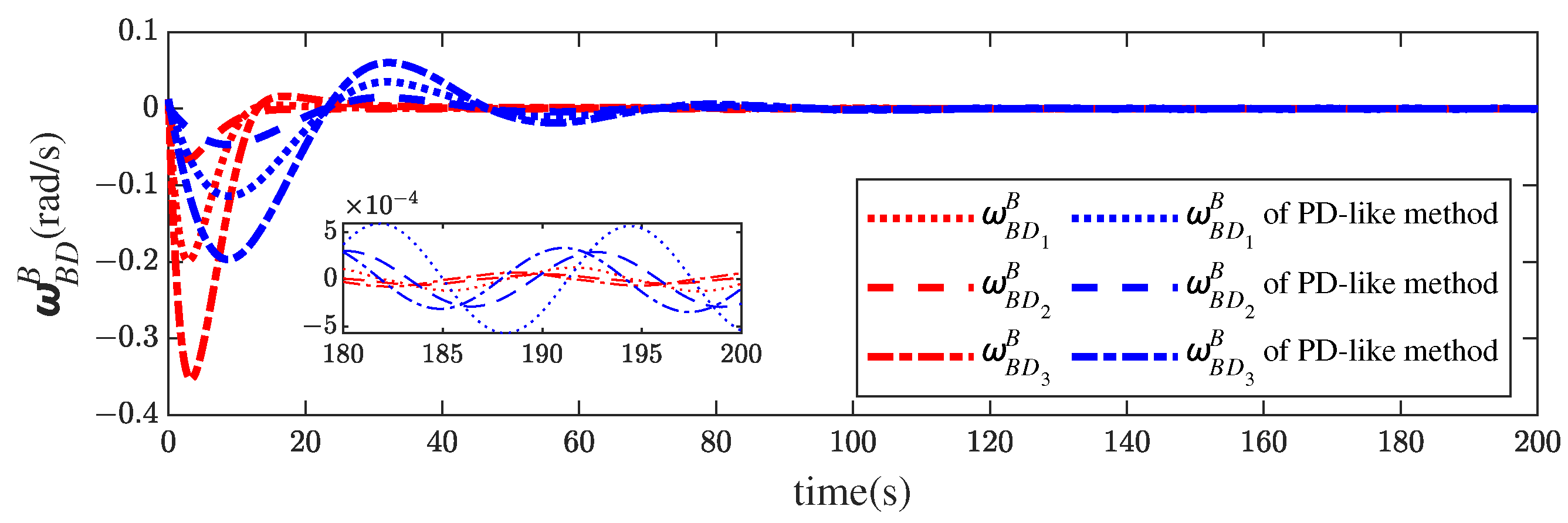
Figure 5 illustrates the MRP histories of the follower spacecraft relative to the desired coordinate frame. Similar to the results of the translational motion, the attitude errors are smaller as well. Figure 6 provides the profiles of the relative angular velocity, where the relative angular velocity governed by the proposed controller changes more aggressively to enable fast convergence. Obviously, the proposed control scheme outperforms the PD-like controller in attitude control, too.
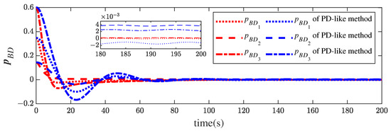
Figure 5.
Relative attitude histories of the proposed method and the PD-like method in [13].

Figure 6.
Relative angular velocity histories of the proposed method and the PD-like method in [13].
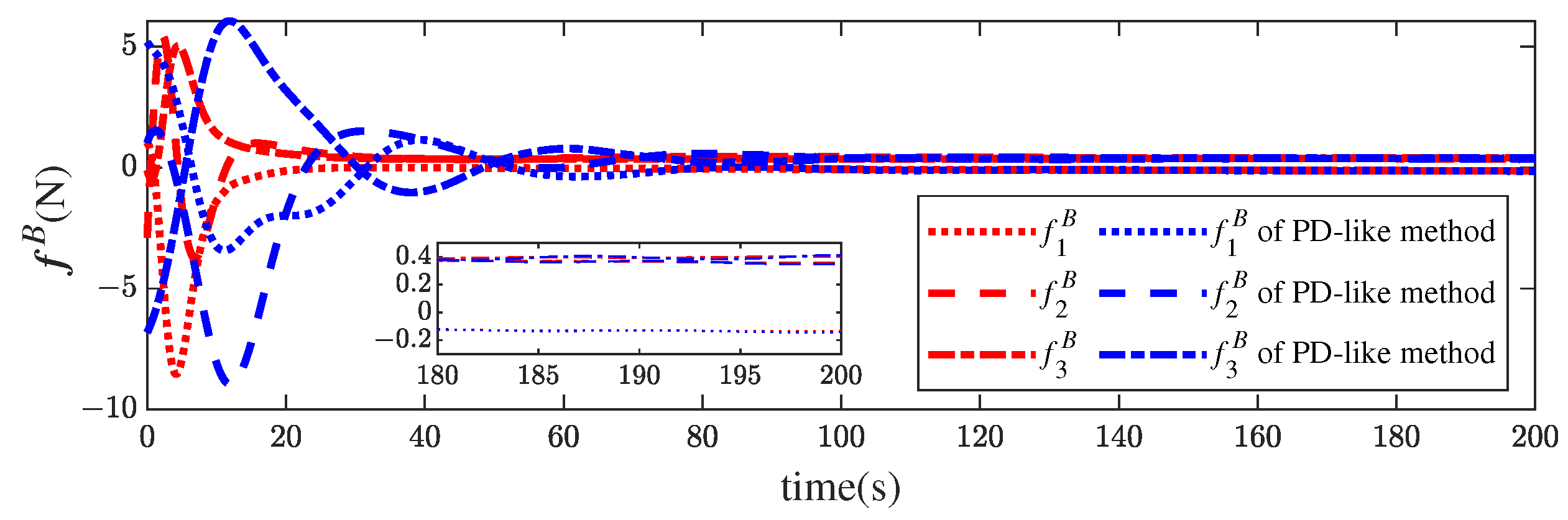
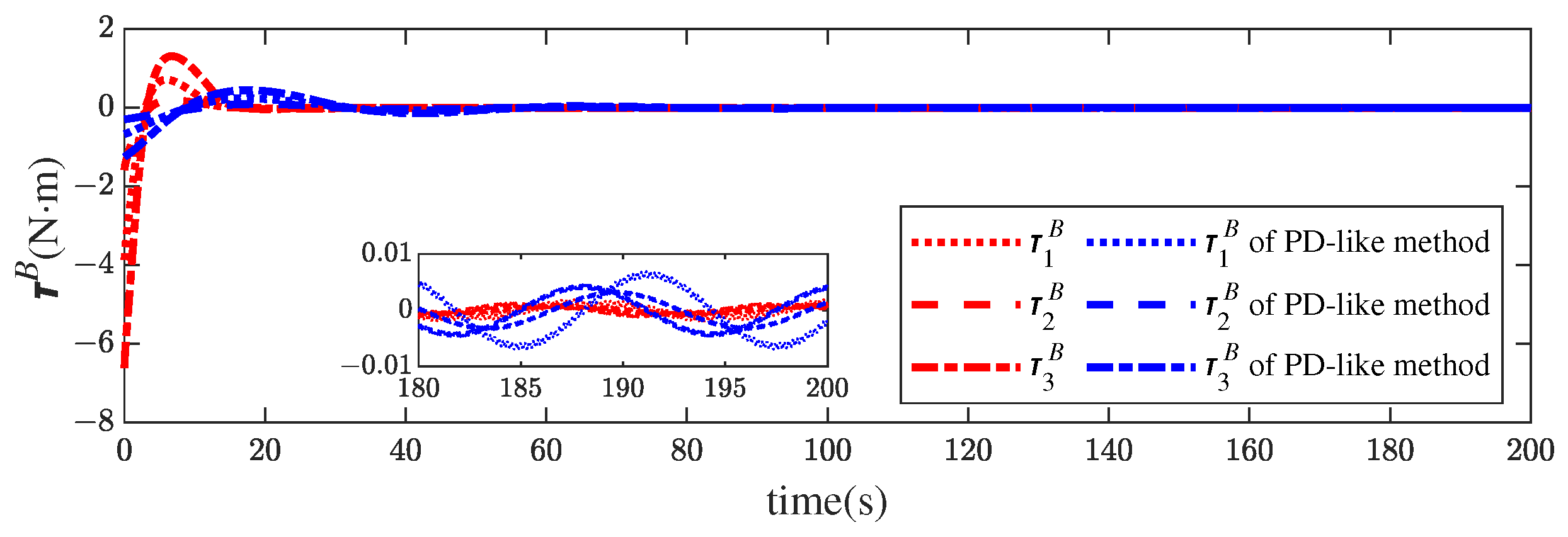
The time histories of the control force and torque are presented in Figure 7 and Figure 8, respectively. Though the relative position of the finite-time controller converges faster than that in [13], both the force and torque magnitudes of the former are much smaller than those of the latter. Table 3 exhibits more details about the results obtained by comparing the final accuracy of the two methods. The stronger robustness of the proposed approach is indicated by the higher steady accuracy in the presence of disturbances.

Figure 7.
Control force profiles of the proposed method and the PD-like method in [13].

Figure 8.
Control torque profiles of the proposed method and the PD-like method in [13].
Table 3.
Steady accuracy comparison of the two control laws.
5. Conclusions
For the control problem of 6-DOF leader–following spacecraft formation, the relative position–attitude motion between spacecraft is described by a unified model based on twistors. A finite-time control scheme is derived for integrated pose control with the application of homogeneous theory. The effectiveness of the control algorithm is manifested by numerical simulations, and the advantages are shown by comparison with an asymptotic control scheme. Designing an integrated pose controller in the framework of twistors is more straightforward than conventional approaches, and the finite-time algorithm achieves stronger robustness than asymptotic ones. In the future, twistor representation can be extended to distributed cooperative control of multi-spacecraft formations and has great potential for obtaining more accurate and robust control protocols.
Author Contributions
B.Z. and H.H. conceived the research; Y.G. and J.C. designed the algorithm; J.C. produced the simulation results. All authors contributed to the analysis of the results. Y.G. drafted a first version of the manuscript. J.C. and B.Z. revised the manuscript according to the reviewers’ comments. B.Z. and H.H. supervised the research. All authors have read and agreed to the published version of the manuscript.
Funding
This research was funded by the Guangdong Basic and Applied Basic Research Foundation under grants 2022A1515011666 and 2023A1515011582, the National Natural Science Foundation of China under grant 62003268, and the Fundamental Research Funds for the Central Universities under grant G2020KY0503.
Institutional Review Board Statement
Not applicable.
Informed Consent Statement
Not applicable.
Data Availability Statement
Not applicable.
Acknowledgments
This work was supported in part by the Guangdong Basic and Applied Basic Research Foundation under grants 2022A1515011666 and 2023A1515011582, the National Natural Science Foundation of China under grant 62003268, and the Fundamental Research Funds for the Central Universities under grant G2020KY0503. The authors greatly appreciate the financial support.
Conflicts of Interest
The authors declare no conflict of interest.
Abbreviations
The following abbreviations are used in this manuscript:
| APF | Artificial potential field |
| MRP | Modified Rodrigues parameters |
| PD | Proportion differentiation |
| 6-DOF | Six-degree-of-freedom |
| UAS | Uniformly asymptotically stable |
| UFTS | Uniformly finite-time stable |
References
- Di Mauro, G.; Lawn, M.; Bevilacqua, R. Survey on guidance navigation and control requirements for spacecraft formation-flying missions. J. Guid. Control Dyn. 2018, 41, 581–602. [Google Scholar] [CrossRef]
- Chen, Z.; Emami, M.R.; Chen, W. Connectivity preservation and obstacle avoidance in small multi-spacecraft formation with distributed adaptive tracking control. J. Intell. Robot. Syst. 2021, 101, 16. [Google Scholar] [CrossRef]
- Li, L.; Zhang, Y.; Zhang, R. Distributed 6-DOF coordination control for spacecraft formation with disturbance, unmeasurable velocity, and communication delays. IEEE Access 2023, 11, 22680. [Google Scholar] [CrossRef]
- Fan, R.; Chen, X.; Liu, M.; Cao, X. Attitude-orbit coupled sliding mode tracking control for spacecraft formation with event-triggered transmission. ISA Trans. 2022, 124, 338–348. [Google Scholar] [CrossRef] [PubMed]
- Liu, R.; Cao, X.; Liu, M.; Zhu, Y. 6-DOF fixed-time adaptive tracking control for spacecraft formation flying with input quantization. Inf. Sci. 2019, 475, 82–99. [Google Scholar] [CrossRef]
- Hintz, G.R. Survey of orbit element sets. J. Guid. Control Dyn. 2008, 31, 785–790. [Google Scholar] [CrossRef]
- Yang, J.; Stoll, E. Adaptive sliding mode control for spacecraft proximity operations based on dual quaternions. J. Guid. Control Dyn. 2019, 42, 2356–2368. [Google Scholar] [CrossRef]
- Mas, I.; Kitts, C. Quaternions and dual quaternions: Singularity-free multirobot formation control. J. Intell. Robot. Syst. 2017, 87, 643–660. [Google Scholar] [CrossRef]
- Abaunza, H.; Castillo, P.; Victorino, A.; Lozano, R. Dual quaternion modeling and control of a quad-rotor aerial manipulator. J. Intell. Robot. Syst. 2017, 88, 267–283. [Google Scholar] [CrossRef]
- Wang, J.; Liang, H.; Sun, Z.; Zhang, S.; Liu, M. Finite-time control for spacecraft formation with dual-number-based description. J. Guid. Control Dyn. 2012, 35, 950–962. [Google Scholar] [CrossRef]
- Li, C.; Zou, H.; Shi, D.; Song, J.; Wang, J. Proportional-integral-type event-triggered coupled attitude and orbit tracking control using dual quaternions. IEEE Trans. Aerosp. Electron. Syst. 2022, 58, 3021–3036. [Google Scholar] [CrossRef]
- Filipe, N.; Kontitsis, M.; Tsiotras, P. Extended Kalman filter for spacecraft pose estimation using dual quaternions. J. Guid. Control Dyn. 2015, 38, 1625–1641. [Google Scholar] [CrossRef]
- Deng, Y.; Wang, Z. Modeling and control for spacecraft relative pose motion by using twistor representation. J. Guid. Control Dyn. 2016, 39, 1147–1154. [Google Scholar] [CrossRef]
- Hestenes, D.; Fasse, E.D. Homogeneous rigid body mechanics with elastic coupling. In Applications of Geometric Algebra in Computer Science and Engineering; Birkhäuser Boston: Boston, MA, USA, 2002. [Google Scholar]
- Deng, Y.; Wang, Z.; Liu, L. Unscented Kalman filter for spacecraft pose estimation using twistors. J. Guid. Control Dyn. 2016, 39, 1844–1856. [Google Scholar] [CrossRef]
- Zhang, B.; Cai, Y. Twistor-based pose control for asteroid landing with path constraints. Nonlinear Dyn. 2020, 100, 2427–2448. [Google Scholar] [CrossRef]
- Zhang, B.; Zhang, Y.; Bai, J. Twistor based adaptive pose control of spacecraft for landing on an asteroid with collision avoidance. IEEE Trans. Aerosp. Electron. 2021, 58, 152–167. [Google Scholar] [CrossRef]
- Zhang, B.; Li, F. Adaptive finite-time control for six-degree-of-freedom leader-following spacecraft formation using twistors. Adv. Space Res. 2022, 70, 1297–1311. [Google Scholar] [CrossRef]
- Zhang, B.; Chen, J.; Hu, B. Distributed control of 6-DOF leader-following multi-spacecraft formation near an asteroid based on scaled twistors. IEEE Trans. Aerosp. Electron. 2023, 59, 1168–1182. [Google Scholar] [CrossRef]
- Bhat, S.P.; Bernstein, D.S. Finite-time stability of continuous autonomous systems. SIAM J. Control Optim. 2000, 38, 751–766. [Google Scholar] [CrossRef]
- Uppal, A.A.; Azam, M.R.; Iqbal, J. Sliding mode control in dynamic systems. Electronics 2023, 12, 2970. [Google Scholar] [CrossRef]
- Gui, H.; Wang, Y.; Su, W. Hybrid global finite-time dual-quaternion observer and controller for velocity-free spacecraft pose tracking. IEEE Trans. Control Syst. Technol. 2021, 29, 2129–2141. [Google Scholar] [CrossRef]
- Zhang, Y.; Ma, C.; Ma, S.; Pan, J.; Sui, X.; Lin, B.; Shi, M. Rigid–flexible coupled system attitude–orbit integration fixed-time control. Electronics 2023, 12, 3329. [Google Scholar] [CrossRef]
- Gui, H.; Jin, L.; Xu, S. Simple finite-time attitude stabilization laws for rigid spacecraft with bounded inputs. Aerosp. Sci. Technol. 2015, 42, 176–186. [Google Scholar] [CrossRef]
- Ma, G.; Wang, Y.; Guo, Y.; Dong, H. Velocity-free finite-time relative 6-DOF control for rigid spacecraft. Adv. Space Res. 2023, 71, 4521–4533. [Google Scholar] [CrossRef]
- Zhang, J.; Wang, Y.; Jia, J.; Chi, C.; Li, H. Collision avoidance second order sliding mode control of satellite formation with air-floated platform semi-physical simulation. Electronics 2023, 12, 3179. [Google Scholar] [CrossRef]
- Gui, H.; Vukovich, G. Global finite-time attitude tracking via quaternion feedback. Syst. Control Lett. 2016, 97, 176–183. [Google Scholar] [CrossRef]
- Pomet, J.-B.; Samson, C. Exponential stabilization of nonholonomic systems in power form. In Proceedings of the IFAC Symposium on Robust Control Design, Rio de Janeiro, Brazil, 14–16 September 1994. [Google Scholar]
- Hong, Y.; Jiang, Z.-P.; Feng, G. Finite-time input-to-state stability and applications to finite-time control design. SIAM J. Control Optim. 2008, 41, 2466–2471. [Google Scholar] [CrossRef]
- Hong, Y.; Jie, H.; Xu, Y. On an output feedback finite-time stabilization problem. IEEE Trans. Autom. Control 2001, 46, 305–309. [Google Scholar] [CrossRef]
- Tsiotras, P.; Valverde, A. Dual quaternions as a tool for modeling, control, and estimation for spacecraft robotic servicing missions. J. Astronaut. Sci. 2020, 67, 595–629. [Google Scholar] [CrossRef]
- Khalil, H. Nonlinear Systems, 3rd ed.; Prentice Hall: Upper Saddle River, NJ, USA, 2002. [Google Scholar]

Disclaimer/Publisher’s Note: The statements, opinions and data contained in all publications are solely those of the individual author(s) and contributor(s) and not of MDPI and/or the editor(s). MDPI and/or the editor(s) disclaim responsibility for any injury to people or property resulting from any ideas, methods, instructions or products referred to in the content. |
© 2023 by the authors. Licensee MDPI, Basel, Switzerland. This article is an open access article distributed under the terms and conditions of the Creative Commons Attribution (CC BY) license (https://creativecommons.org/licenses/by/4.0/).