
Zero-Voltage Ride-Through Scheme of PMSG Wind Power System Based on NLESO and GFTSMC


Abstract
:1. Introduction
- A nonlinear robust current feedforward control based on an NLESO and GFTSMC is proposed;
- A ZVRT scheme for PMSG based on a BC and nonlinear robust current feedforward control is proposed;
- A comparison with conventional double closed-loop control is made to show the validity of the proposed nonlinear robust current feedforward control and ZVRT scheme.
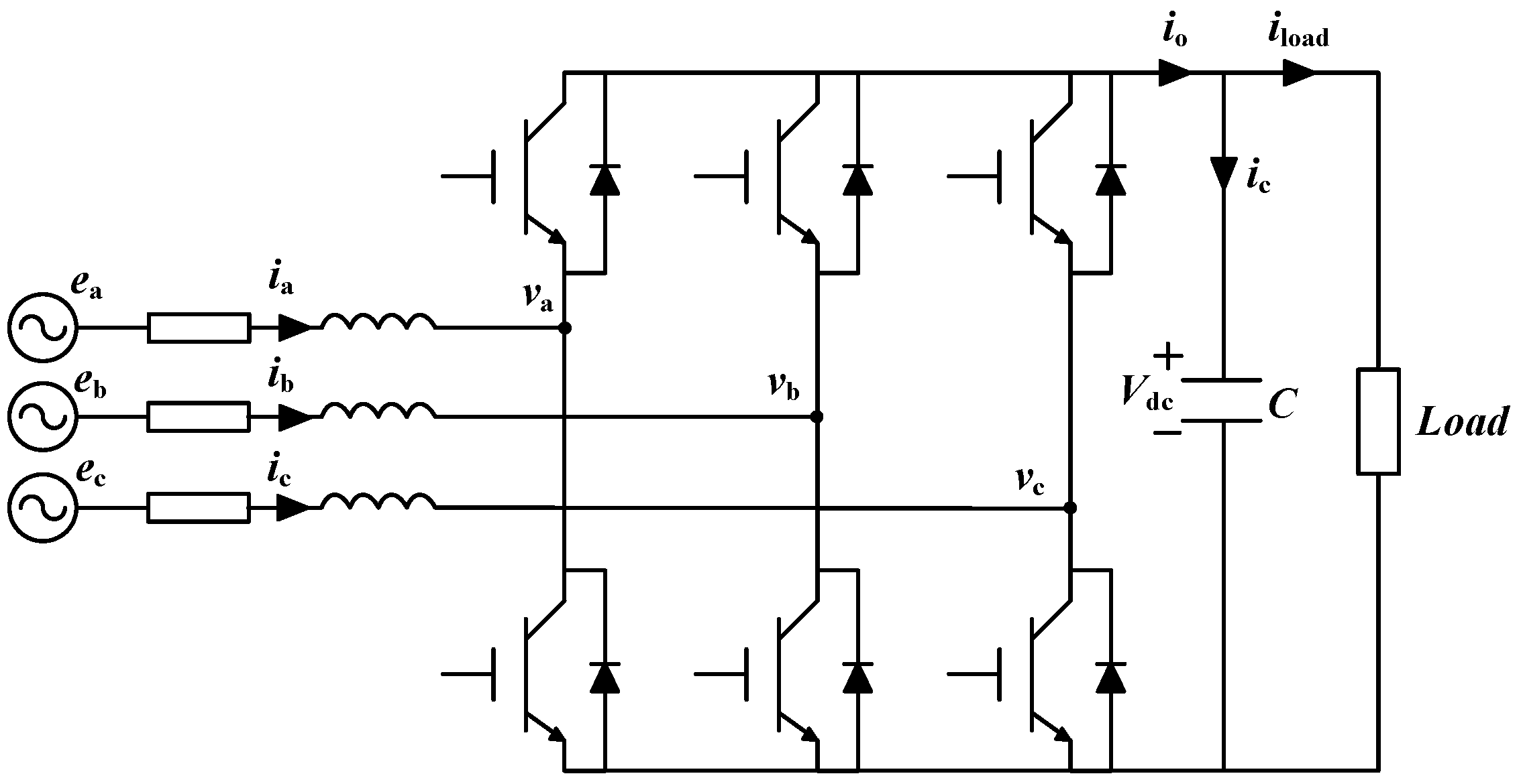
2. Basic Description of PMSG Wind Power Systems
3. Conventional Control Strategy of PMSG Wind Power Systems
3.1. MSC Control
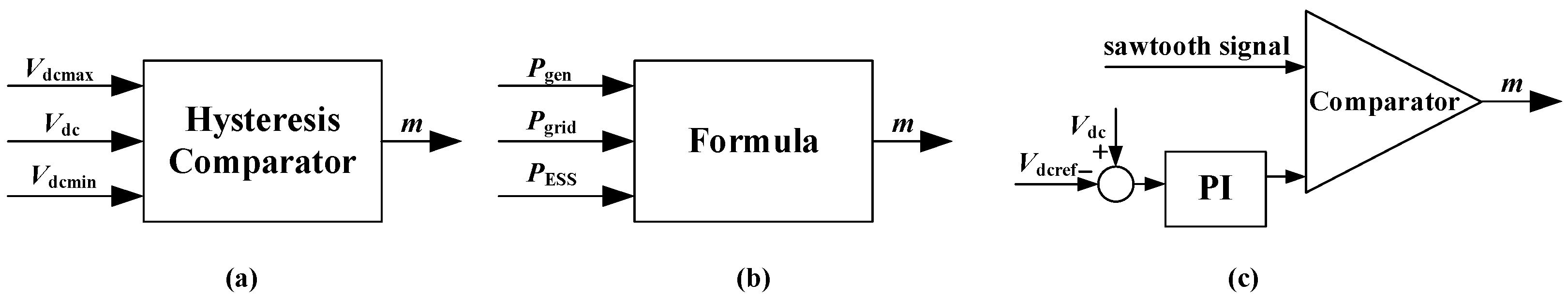
3.2. BC Control
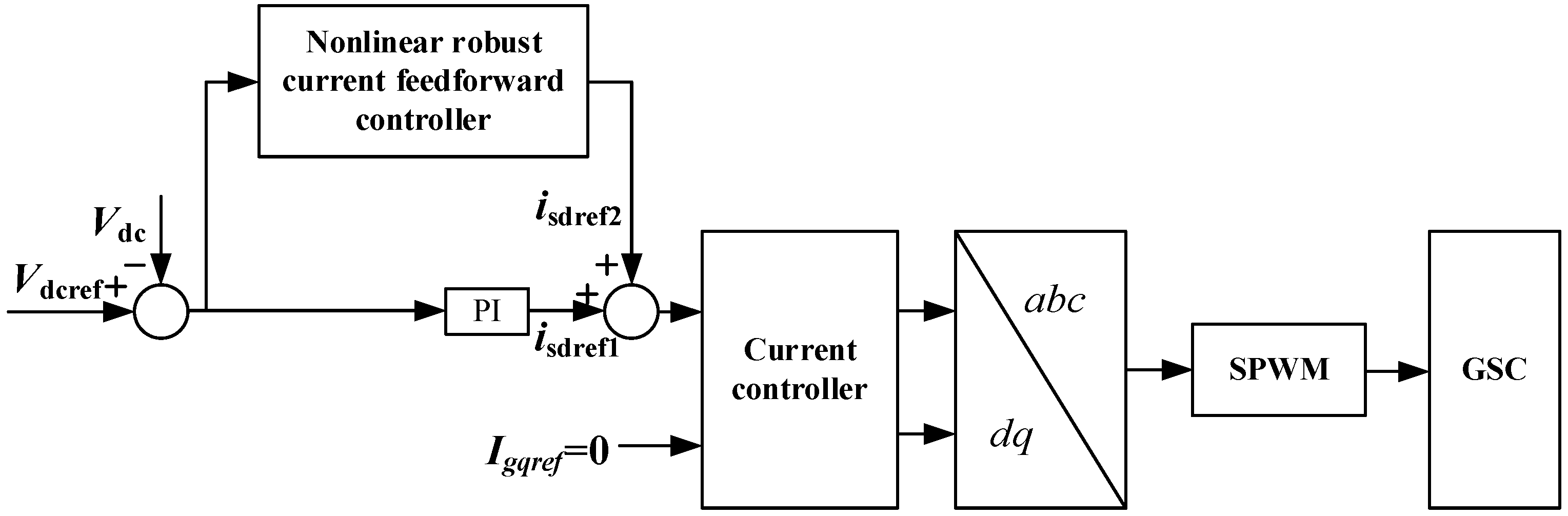
3.3. GSC Control
4. Proposed Nonlinear Robust Current Feedforward Control Based on an NLESO and GFTSMC
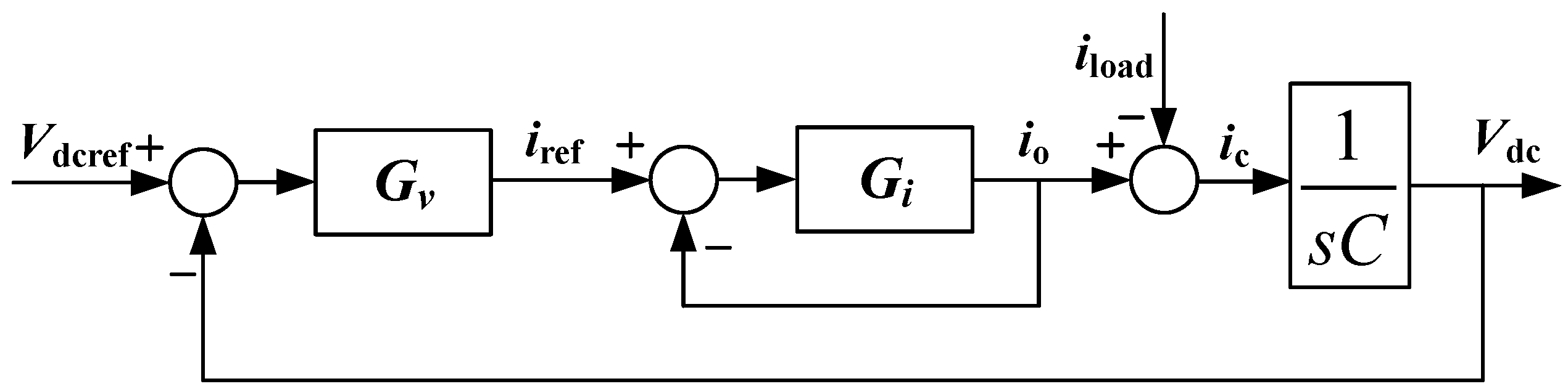
4.1. The Basic Principle of Current Feedforward Control
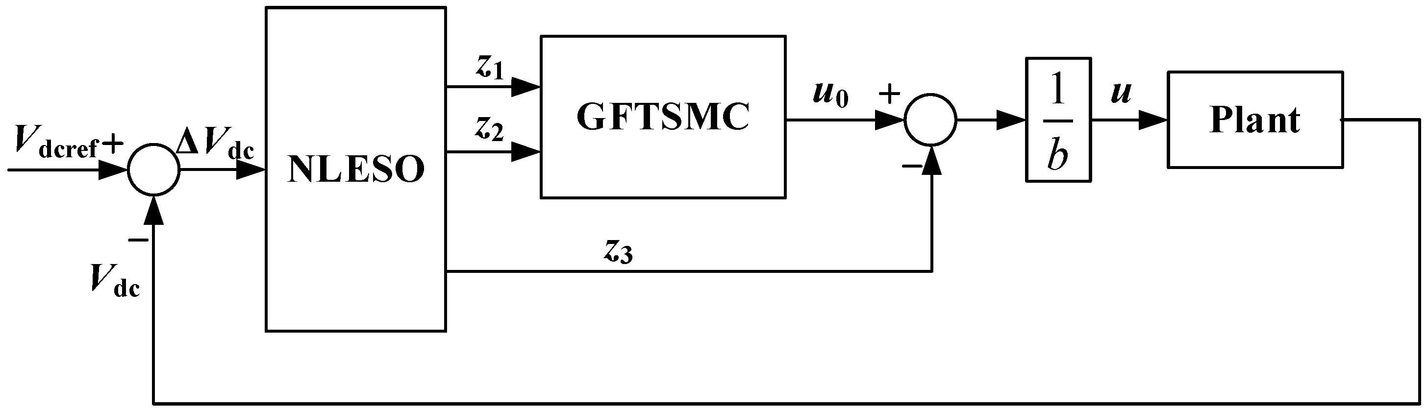
4.2. Proposed Nonlinear Robust Current Feedforward Control
4.3. Stability Analysis
5. Simulation Results
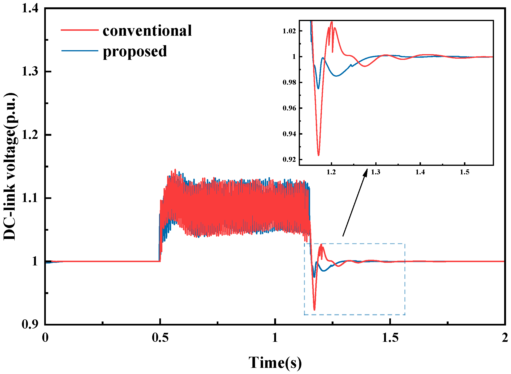
5.1. Verification of Proposed Nonlinear Robust Current Feedforward Control
5.2. Performance of PMSG Wind Power System under a Zero Voltage Grid Fault
6. Conclusions
- Simulation results show that the proposed nonlinear robust current feedforward control has an excellent control effect on DC-link voltage. This is specifically reflected in reducing the DC-link voltage fluctuation and recovery time after the fault.
- This scheme realizes ZVRT with a high performance. DC-link voltage is kept within a safe range during the grid fault. All indicators are within normal values.
- The NLESO and GFTSMC change the current feedforward control into a nonlinear robust current feedforward control by utilizing the DC-link voltage as the input signal. This reduces the number of current transformers and saves cost.
Author Contributions
Funding
Data Availability Statement
Conflicts of Interest
References
- Nasiri, M.; Milimonfared, J.; Fathi, S.H. A review of low-voltage ride-through enhancement methods for permanent magnet synchronous generator-based wind turbines. Renew. Sustain. Energy Rev. 2015, 47, 399–415. [Google Scholar] [CrossRef]
- Jahanpour-Dehkordi, M.; Vaez-Zadeh, S.; Mohammadi, J. Development of a Combined Control System to Improve the Performance of a PMSG-Based Wind Energy Conversion System under Normal and Grid Fault Conditions. IEEE Trans. Energy Convers. 2019, 34, 1287–1295. [Google Scholar] [CrossRef]
- Zhou, A.; Li, Y.W.; Mohamed, Y. Mechanical Stress Comparison of PMSG Wind Turbine LVRT Methods. IEEE Trans. Energy Convers. 2021, 36, 682–692. [Google Scholar] [CrossRef]
- Kim, K.; Jeung, Y.; Lee, D.; Kim, H. LVRT Scheme of PMSG Wind Power Systems Based on Feedback Linearization. IEEE Trans. Power Electron. 2012, 27, 2376–2384. [Google Scholar] [CrossRef]
- Al-Shetwi, A.Q.; Hannan, M.A.; Jern, K.P.; Mansur, M.; Mahlia, T.M.I. Grid-connected renewable energy sources: Review of the recent integration requirements and control methods. J. Clean. Prod. 2020, 253, 119831. [Google Scholar] [CrossRef]
- Qin, K.; Wang, S.; Kang, Z. Research on Zero-Voltage Ride through Control Strategy of Doubly Fed Wind Turbine. Energies 2021, 14, 2287. [Google Scholar] [CrossRef]
- Ibrahim, R.A.; Hamad, M.S.; Dessouky, Y.G.; Williams, B.W. A review on recent low voltage ride-through solutions for PMSG wind turbine. In Proceedings of the International Symposium on Power Electronics Power Electronics, Electrical Drives, Automation and Motion, Sorrento, Italy, 20–22 June 2012; pp. 265–270. [Google Scholar]
- Wang, J.; Ben, Y.; Zhang, J.; Feng, H. Low voltage ride-through control strategy for a wind turbine with permanent magnet synchronous generator based on operating simultaneously of rotor energy storage and a discharging resistance. Energy Rep. 2022, 8, 5861–5870. [Google Scholar] [CrossRef]
- Nasiri, M.; Arzani, A. Robust control scheme for the braking chopper of PMSG-based wind turbines—A comparative assessment. Int. J. Electr. Power Energy Syst. 2021, 134, 107322. [Google Scholar] [CrossRef]
- Sakipour, R.; Abdi, H. Voltage stability improvement of wind farms by self-correcting static volt-ampere reactive compensator and energy storage. Int. J. Electr. Power Energy Syst. 2022, 140, 108082. [Google Scholar] [CrossRef]
- Huang, C.; Xiao, X.Y.; Zheng, Z.; Wang, Y. Cooperative Control of SFCL and SMES for Protecting PMSG-Based WTGs under Grid Faults. IEEE Trans. Appl. Supercond. 2019, 29, 1–6. [Google Scholar] [CrossRef]
- Sathya, E.; Maruthupandi, P. Enhancement of Low Voltage Ride through Capability for PMSG Based Wind Energy Conversion System with Super Capacitor. In Proceedings of the 2018 4th International Conference on Electrical Energy Systems (ICEES), Chennai, India, 7–9 February 2018; pp. 57–60. [Google Scholar]
- Chen, L.; Chen, H.; Yang, J.; Zhu, L.; Tang, Y.; Koh, L.H.; Xu, Y.; Zhang, C.; Liao, Y.; Ren, L. Comparison of Superconducting Fault Current Limiter and Dynamic Voltage Restorer for LVRT Improvement of High Penetration Microgrid. IEEE Trans. Appl. Supercond. 2017, 27, 1–7. [Google Scholar] [CrossRef]
- Jin, J.X.; Yang, R.H.; Zhang, R.T.; Fan, Y.J.; Xie, Q.; Chen, X.Y. Combined low voltage ride through and power smoothing control for DFIG/PMSG hybrid wind energy conversion system employing a SMES-based AC-DC unified power quality conditioner. Int. J. Electr. Power Energy Syst. 2021, 128, 106733. [Google Scholar] [CrossRef]
- Benali, A.; Khiat, M.; Allaoui, T.; Denaï, M. Power Quality Improvement and Low Voltage Ride through Capability in Hybrid Wind-PV Farms Grid-Connected Using Dynamic Voltage Restorer. IEEE Access 2018, 6, 68634–68648. [Google Scholar] [CrossRef]
- Feyzi, M.; Roozbehani, S.; Liasi, S.G. Low Voltage Ride through Improvement of Machine Side and Grid Side Converters of PMSG-Wind Turbine Based on SMC. In Proceedings of the 2022 13th Power Electronics, Drive Systems, and Technologies Conference (PEDSTC), Tehran, Iran, 1–3 February 2022; pp. 251–257. [Google Scholar]
- Calle-Prado, A.; Alepuz, S.; Bordonau, J.; Nicolas-Apruzzese, J.; Cortés, P.; Rodriguez, J. Model Predictive Current Control of Grid-Connected Neutral-Point-Clamped Converters to Meet Low-Voltage Ride-through Requirements. IEEE Trans. Ind. Electron. 2015, 62, 1503–1514. [Google Scholar] [CrossRef]
- Alhejji, A.; Bouzid, Y. Robust Adaptive PI Controller of Low Voltage Ride-through for PMSG-Based Wind Turbine. In Proceedings of the 2019 6th International Conference on Control, Decision and Information Technologies (CoDIT), Paris, France, 23–26 April 2019; pp. 1233–1237. [Google Scholar]
- Uehara, A.; Pratap, A.; Goya, T.; Senjyu, T.; Yona, A.; Urasaki, N.; Funabashi, T. A Coordinated Control Method to Smooth Wind Power Fluctuations of a PMSG-Based WECS. IEEE Trans. Energy Convers. 2011, 26, 550–558. [Google Scholar] [CrossRef]
- Xing, P.; Fu, L.; Wang, G.; Wang, Y.; Zhang, Y. A compositive control method of low-voltage ride through for PMSG-based wind turbine generator system. IET Gener. Transm. Distrib. 2018, 12, 117–125. [Google Scholar] [CrossRef]
- Wang, M.; Tian, Y.; Feng, X.; Chen, G. A hybrid LVRT control scheme for PMSG wind power system. In Proceedings of the 7th International Power Electronics and Motion Control Conference, Harbin, China, 2–5 June 2012; pp. 1173–1177. [Google Scholar]
- Junejo, A.K.; Xu, W.; Mu, C.; Ismail, M.M.; Liu, Y. Adaptive Speed Control of PMSM Drive System Based a New Sliding-Mode Reaching Law. IEEE Trans. Power Electron. 2020, 35, 12110–12121. [Google Scholar] [CrossRef]
- Xu, W.; Junejo, A.K.; Liu, Y.; Hussien, M.G.; Zhu, J. An Efficient Antidisturbance Sliding-Mode Speed Control Method for PMSM Drive Systems. IEEE Trans. Power Electron. 2021, 36, 6879–6891. [Google Scholar] [CrossRef]
- Haque, M.E.; Negnevitsky, M.; Muttaqi, K.M. A Novel Control Strategy for a Variable-Speed Wind Turbine with a Permanent-Magnet Synchronous Generator. IEEE Trans. Ind. Appl. 2010, 46, 331–339. [Google Scholar] [CrossRef]
- Ghany, A.A.; Shehata, E.G.; Elsayed, A.-H.M.; Mohamed, Y.S.; Haes Alhelou, H.; Siano, P.; Diab, A.A.Z. Novel Switching Frequency FCS-MPC of PMSG for Grid-Connected Wind Energy Conversion System with Coordinated Low Voltage Ride through. Electronics 2021, 10, 492. [Google Scholar] [CrossRef]
- Babaghorbani, B.; Beheshti, M.T.; Talebi, H.A. A Lyapunov-based model predictive control strategy in a permanent magnet synchronous generator wind turbine. Int. J. Electr. Power Energy Syst. 2021, 130, 106972. [Google Scholar] [CrossRef]
- Nasiri, M.; Mohammadi, R. Peak Current Limitation for Grid Side Inverter by Limited Active Power in PMSG-Based Wind Turbines during Different Grid Faults. IEEE Trans. Sustain. Energy 2017, 8, 3–12. [Google Scholar] [CrossRef]
- Kim, C.; Kim, W. Enhanced Low-Voltage Ride-through Coordinated Control for PMSG Wind Turbines and Energy Storage Systems Considering Pitch and Inertia Response. IEEE Access 2020, 8, 212557–212567. [Google Scholar] [CrossRef]
- Huang, C.; Zheng, Z.; Xiao, X.; Chen, X. Enhancing low-voltage ride-through capability of PMSG based on cost-effective fault current limiter and modified WTG control. Electr. Power Syst. Res. 2020, 185, 106358. [Google Scholar] [CrossRef]
- Pannell, G.; Zahawi, B.; Atkinson, D.J.; Missailidis, P. Evaluation of the Performance of a DC-Link Brake Chopper as a DFIG Low-Voltage Fault-Ride-through Device. IEEE Trans. Energy Convers. 2013, 28, 535–542. [Google Scholar] [CrossRef]
- Orlando, N.A.; Liserre, M.; Mastromauro, R.A.; Dell, A. A Survey of Control Issues in PMSG-Based Small Wind-Turbine Systems. IEEE Trans. Ind. Inform. 2013, 9, 1211–1221. [Google Scholar] [CrossRef]


| System Component | Parameters | Values |
|---|---|---|
| Turbine | Wind speed | 11 m/s |
| Blade radius | 45 m | |
| Air density | 1.225 kg/m3 | |
| Max. Power conv. coeff | 0.48 | |
| Rated turbine speed | 17.3 rpm | |
| Shaft | Moment of inertia | 6.1 × 10⁶ kgm2 |
| Shaft stiffness | 8.3 × 10⁷ Nm/rad | |
| Shaft mutual damping | 1.4 × 10⁶ Nms/rad | |
| PMSG | Rated power | 2.5 MW |
| Rated voltage | 690 V | |
| BTB converter with BC | DC-link voltage | 1200 V |
| DC-link capacitance | 0.023 F | |
| Braking chopper resistance | 0.67 Ω | |
| Vdcref-BC | 1.1 p.u. | |
| Grid | PCC voltage | 690 V |
| Grid voltage | 35 KV | |
| Grid frequency | 50 Hz |
| Controller Component | Parameters | Values |
|---|---|---|
| NLESO | k1 | 100 |
| k2 | 3750 | |
| k3 | 62,500 | |
| b | −2900 | |
| GFTSMC | α | 0.5 |
| β | 0.1 | |
| p | 9 | |
| q | 5 | |
| ϕ | 2 | |
| Γ | 4 |
Disclaimer/Publisher’s Note: The statements, opinions and data contained in all publications are solely those of the individual author(s) and contributor(s) and not of MDPI and/or the editor(s). MDPI and/or the editor(s) disclaim responsibility for any injury to people or property resulting from any ideas, methods, instructions or products referred to in the content. |
© 2023 by the authors. Licensee MDPI, Basel, Switzerland. This article is an open access article distributed under the terms and conditions of the Creative Commons Attribution (CC BY) license (https://creativecommons.org/licenses/by/4.0/).
Share and Cite
Kang, Z.; Li, J. Zero-Voltage Ride-Through Scheme of PMSG Wind Power System Based on NLESO and GFTSMC. Electronics 2023, 12, 4348. https://doi.org/10.3390/electronics12204348
Kang Z, Li J. Zero-Voltage Ride-Through Scheme of PMSG Wind Power System Based on NLESO and GFTSMC. Electronics. 2023; 12(20):4348. https://doi.org/10.3390/electronics12204348
Chicago/Turabian StyleKang, Zhongjian, and Jinfeng Li. 2023. "Zero-Voltage Ride-Through Scheme of PMSG Wind Power System Based on NLESO and GFTSMC" Electronics 12, no. 20: 4348. https://doi.org/10.3390/electronics12204348
APA StyleKang, Z., & Li, J. (2023). Zero-Voltage Ride-Through Scheme of PMSG Wind Power System Based on NLESO and GFTSMC. Electronics, 12(20), 4348. https://doi.org/10.3390/electronics12204348