Article

Adaptive Active Inertia Control Strategy of MMC-HVDC Systems for Flexible Frequency Support

1
College of Energy and Electrical Engineering, Hohai University, Nanjing 211100, China
2
College of Engineering and Physical Sciences, University of Birmingham, Birmingham B15 2TT, UK
3
College of Electrical Engineering, Tibet Agricultural and Animal Husbandry University, Linzhi 860000, China
*
Author to whom correspondence should be addressed.
Electronics 2023, 12(20), 4288; https://doi.org/10.3390/electronics12204288
Submission received: 20 August 2023 / Revised: 9 October 2023 / Accepted: 14 October 2023 / Published: 16 October 2023
(This article belongs to the Section Power Electronics)

Abstract

:
The Modular Multilevel Converter High Voltage Direct Current Transmission (MMC-HVDC) technology is considered to be the most feasible choice for high-voltage and high-power transmission systems, and its flexibility and high controllability provide a new solution for renewable energy grid integration. The MMC topology contains a large number of capacitors, which enables it to provide a certain active inertia support for the connected AC system. Different from a synchronous machine, the active inertia control of an MMC can flexibly adjust a system’s inertia-supporting power by changing the control parameters. By introducing a variation of the Sigmoid function with amplitude-limiting capability, this paper proposes an adaptive active inertia control strategy for the MMC-HVDC system. The proposed scheme adjusts the inertia constant adaptively according to the frequency change rate of the AC system, which can better respond to the frequency recovery performance. Finally, the MMC-HVDC simulation model is established in PSCAD/EMTDC to verify the effectiveness of the proposed control strategy.

1. Introduction

Wind power and photovoltaic and other clean energy sources have the advantages of environmental friendliness and sustainable capacity, making them effective ways to build a new power system guided by the goal of achieving “double carbon” [1,2]. However, limited by climate and terrain conditions, the output power of new energy has a high degree of uncertainty and randomness, which brings potential risks to the operation of the power system. The high voltage direct current based on the modular multilevel converter (MMC-HVDC) has become the mainstream direction of HVDC technology development owing to its advantages of high voltage level, large transmission capacity, high quality of power waveform, superior fault controllability, etc. Additionally, it has significant advantages in new energy grid connections [3,4,5].
In new power systems with a high proportion of power electronics, the effective inertia of the system gradually decreases. When the AC system suffers frequency fluctuations, the inertia support capacity of the system becomes insufficient, and the stable operation is affected [6]. Due to the flexible control of power electronics converters, the virtual synchronous generator (VSG) control, which simulates a synchronous generator, becomes an effective means to improve the frequency support ability of a power grid. In Ref. [7], an adaptive control strategy of the VSG moment of inertia and damping coefficient is proposed that dynamically adjusts the inertia damping coefficient by tracking the angular velocity of the VSG rotor to improve the operation capability of the system. In Ref. [8], a data-driven VSG control method based on reinforcement learning and adaptive dynamic programming is proposed that considers unknown system dynamics and different power grid conditions. After analyzing the power angle characteristics of VSG under stable operation and output current saturation conditions, Ref. [9] calculates the fault critical clearance angle by using the equal area criterion. On this basis, an adaptive control strategy of an inertia and damping coefficient is proposed to prolong the critical clearance time (CCT), thereby reducing the frequency fluctuation and improving the transient stability of the system. For a microgrid, Refs. [10,11] propose an adaptive virtual inertia control strategy and establish a small signal model to analyze the stability of the range of virtual inertia constants. However, the above research mainly focuses on the improved VSG control from the perspective of system stability enhancement. Different from a synchronous machine, the VSG control of a power converter can flexibly adjust system inertia by changing control parameters. Refs. [12,13] propose frequency support technology for a photovoltaic high-penetration power system based on adaptive virtual inertial control and design the virtual inertial adaptive parameters of each photovoltaic power station. Ref. [13] proposes an effective adaptive virtual inertial control paradigm to evaluate the impact of photovoltaic and wind power on microgrids. In Ref. [14], an adaptive inertial control strategy is proposed based on the fuzzy control, and a fuzzy controller with feedback mechanism is designed. Ref. [15] proposes a coordinated adaptive control method of VSG inertia coefficient J and damping coefficient D. By analyzing the power angle curve, the control functions of J and D are determined with the damping ratio of the system in consideration. According to the operating characteristics of supercapacitors and batteries, an improved adaptive control strategy with inertial damping is proposed in Ref. [16]. In Ref. [17], a controller with inertial support capability was proposed to construct a cost function by comprehensively considering phase angle deviation, frequency deviation, rate of frequency change (RoCoF) and a reduction factor. Refs. [18,19] compare and introduce three adaptive control strategies of a virtual synchronous generator from different perspectives. In order to avoid high-frequency noise and consider the influence of energy storage on a power grid, a segmented adaptive virtual inertia regulation method is proposed that improves the safety and reliability of the power grid [20,21]. In Ref. [22], control parameters are obtained based on the dissipative Hamilton method, and the adaptive control strategy of the moment of inertia and damping coefficient is proposed to make full use of VSG flexible advantages to suppress power oscillations in power grid.
The VSG control can also be applied in MMC-HVDC systems to improve the frequency response for the connected AC system. The arm submodule of MMC-HVDC contains a large number of capacitors that can provide certain inertia support for the connected AC system. For this reason, scholars have conducted much research [23,24,25,26]. In order to reduce the influence of parameters on MMC-HVDC virtual inertia control and improve its transient and steady-state performance, Ref. [23] introduces additional frequency control based on extended state observer (ESO) and terminal sliding mode control (TSMC) into a virtual synchronous generator (VSG) frequency controller, as well as proves the stability of the controller. Further, Ref. [24] compares traditional synchronous motors with existing voltage source converters, discusses the role of MMC-HVDC virtual inertia control in the transient process, and gives the factors that may affect the frequency deviation. On the basis of considering the dynamic safety constraints of the inertial support source and the MMC-HVDC, an inertial response frequency control method with an energy buffer source is proposed in Ref. [27]. In this method, the rotor motion equation of synchro is embedded into the MMC control loop, and the DC energy buffer control loop is designed. Aiming at the problem of system frequency deterioration caused by the MMC-HVDC grid connection of offshore wind power, Ref. [28] proposes a coordinated control method that considers different wind speeds, releases rotor kinetic energy through fan variable speed control and utilizes MMC-HVDC sub-module electrical energy to participate in frequency regulation. However, its control strategy needs to be designed according to DC voltage deviation, and it is restricted by an information transmission delay. Considering the cascade control loop of MMC, the Receiving End Converter (REC) grid-connected control strategy with real-time inertial support and fast DC voltage control is proposed in Ref. [29], which realizes fast dynamic control of DC voltage. Although virtual inertia control of MMC-HVDC can improve the stable operation of the whole system, it also faces the challenge of fault crossing capability. Therefore, the current limit, voltage drop and phase jump of MMC-HVDC under virtual inertia control are studied in Ref. [30]. However, the above MMC-HVDC active inertia control is mainly based on the fixed inertia constant control parameters, which cannot provide flexible inertia support according to the frequency requirements of the power grid.
In this paper, an adaptive active inertia control strategy for the MMC-HVDC system is proposed by introducing a variation of the Sigmoid function with amplitude limiting capability. The proposed scheme adjusts the inertia constant adaptively according to the frequency change rate of the AC system 2, which can provide more flexible inertia support for AC system 2. Finally, the effectiveness of the proposed control strategy is verified by the simulation of the MMC-HVDC model established in PSCAD.

2. Active Inertia Support Control Strategy for MMC-HVDC System

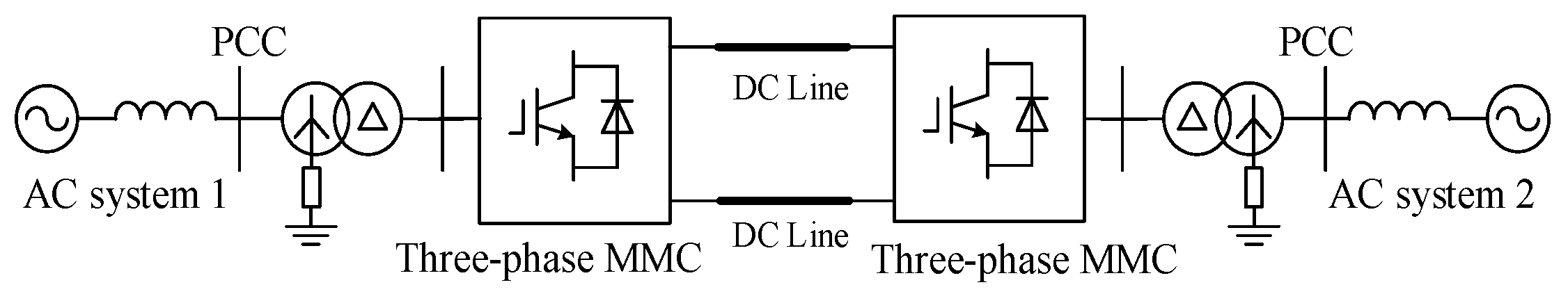
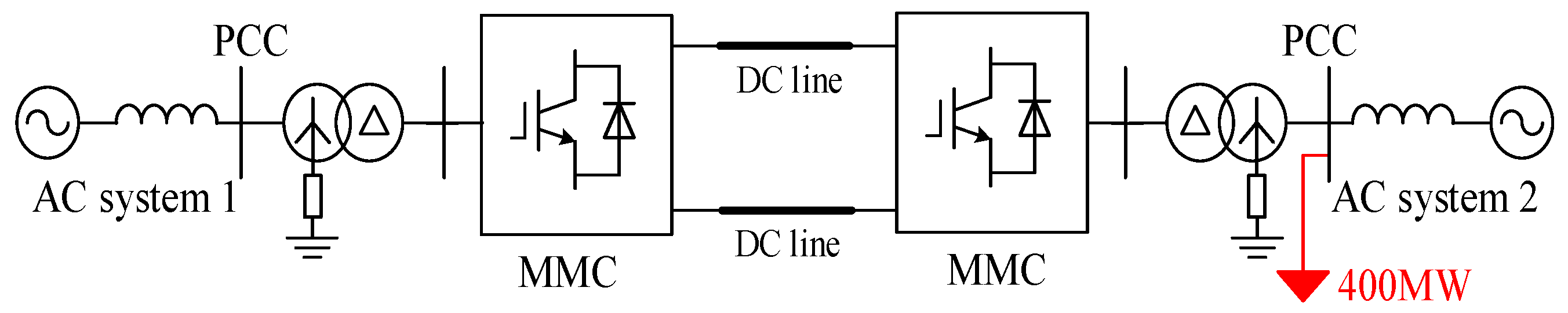
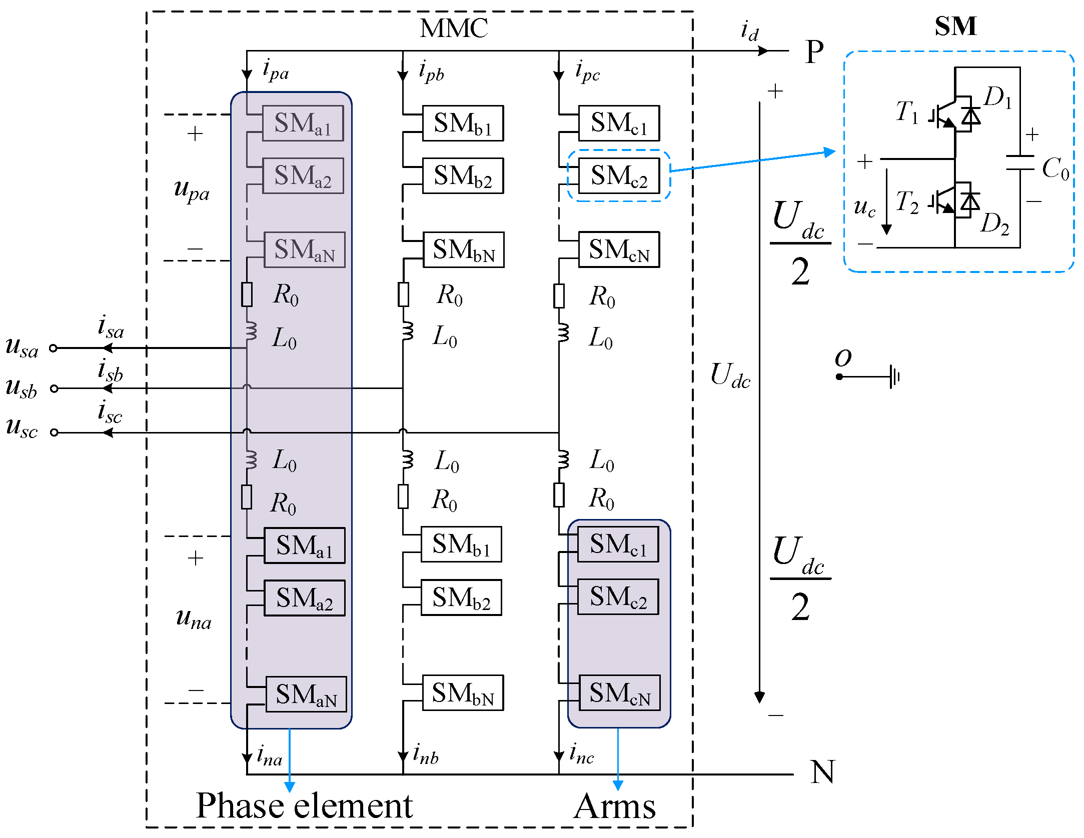
2.1. Typical Architecture of the MMC-HVDC System

The topology of a typical MMC-HVDC system is shown in Figure 1, where the MMC-HVDC converter station at the sending end adopts a fixed active power control strategy to control the rated power transmitted by the system, and the converter station at the receiving end adopts a fixed DC voltage control strategy to control the DC voltage of the system. The structure of the three-phase MMC converter is shown in Figure 2. The MMC converter consists of three phase units and six arms, where C 0 , L 0 and R 0 represent submodule capacitance, arm reactance and equivalent resistance, respectively. In general, the MMC converter adopts the nearest level approximation modulation method and voltage equalization strategy to realize the normal operation of each submodule.

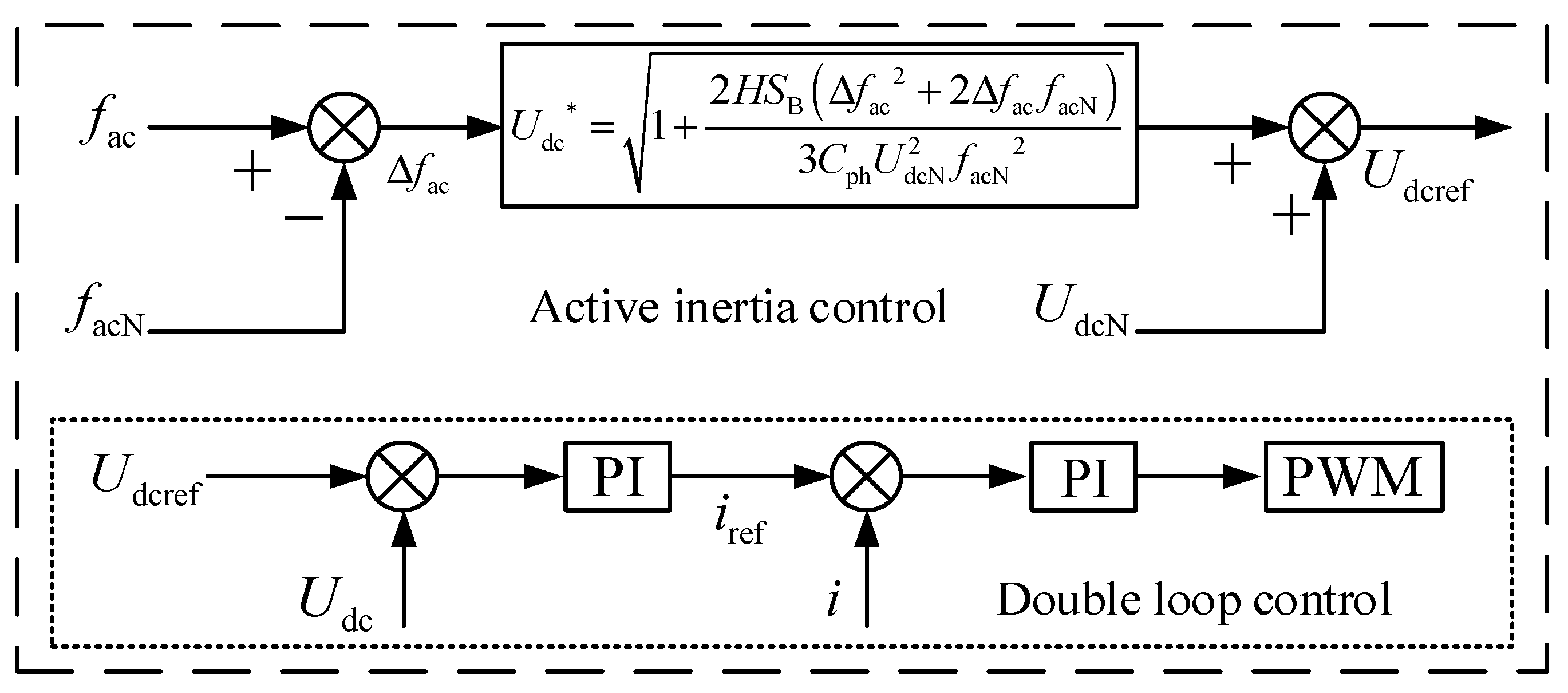
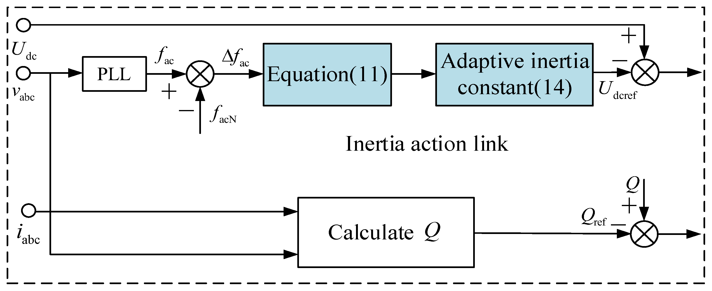
2.2. Active Inertia Support Control Strategy of MMC-HVDC System

The MMC-HVDC system contains hundreds of cascades of capacitor submodules, which can make full use of their stored energy to provide active inertia support for the connected AC system 2. The active inertia support scheme simulates the rotor motion and electromagnetic transient equation of a synchronous generator, and the inertia energy is provided to the system by the MMC submodule capacitor since each phase unit of MMC is composed of 2N submodules in a series, and N sub-module capacitors are put into operation every time. Therefore, it can be considered that the 2N submodules in each phase unit have the same capacitance voltage and are equal to the average capacitance voltage U c of the submodules. Then, the 2N submodules can be equivalent by one capacitor based on the principle that the total energy storage capacity of the capacitor is unchanged, which is shown in (1).
1 2 C ph U dc 2 = 2 N 1 2 C 0 U c 2
where C ph is the capacitance value of the single-phase arm 2N submodule equivalent to a capacitor, C 0 is the capacitance value of each submodule SM in the bridge arm and U dc is the DC voltage of the system. According to the relationship U dc = N U c , it can be obtained that
C ph = 2 N C 0
Then the total capacitor energy W total stored in MMC can be obtained as:
W total = 3 2 C ph U dc 2
When the input and output power of the MMC-HVDC converter station is unbalanced, the energy storage of the converter station changes and satisfies
3 2 C ph ( U dcN 2 U dc 2 ) = Δ P dt
where U dcN is the rated DC voltage and U dc is the actual value of DC voltage of MMC-HVDC.
Since there are a large number of synchronous generators in the traditional AC power grid, when the AC power grid is unbalanced due to faults or load changes, the balance between the mechanical power P T acting on the generator rotor and the electromagnetic power P G output is broken. In the case of ignoring the loss of the generator, the unbalanced power is
Δ P = P G P T
When the unbalanced power acts on the generator rotor, the drive rotor speed changes and meets the following conditions:
1 2 J ω N 2 ω 2 = Δ P dt
where J represents the rotor moment of inertia, ω N is the rated speed of the generator rotor and ω is the actual speed of the generator rotor. The rotor moment of inertia J can be expressed as
J = 2 H S B ω N 2
where H is the inertia time constant of the generator and S B is the reference capacity of the generator. As can be seen from (6), the inertia of the generator and the unbalanced power of the grid will determine the degree of rotor deviation from the rated speed. Under the same external unbalanced power, if the inertia of the generator rotor is larger, the speed deviation from the rated value is smaller, and the anti-disturbance ability is stronger. By comparing (4) and (6), it is found that they are not only similar in form but also in physical meaning. When the synchronous machine in the traditional AC power grid is faced with the external unbalanced power, it uses the rotating rotor to resist the external disturbance through the change of rotor speed and the change of rotor kinetic energy. In the virtual inertia control strategy, MMC-HVDC uses the electrostatic energy stored in the submodule and absorbs or emits energy in the form of capacitor voltage change of the submodule to resist external disturbance through the charge and discharge of the submodule capacitor. Therefore, when there is unbalanced power in the system, the MMC-HVDC converter station can play the role of synchronous machine in the transient process through virtual inertia control and provide a certain inertia support for the system. By equalizing (4) and (6), it can be obtained that
1 2 J ω N 2 ω 2 = 3 2 C ph ( U dcN 2 U dc 2 )
As can be seen from (8), the MMC-HVDC simulates the speed response of synchronous rotor speed under unbalanced power by changing the capacitor voltage of submodules. When the system power is unbalanced, the rotor speed of the synchronous machine changes from ω N to ω , and the MMC-HVDC dynamically adjusts the DC voltage from U dcN to U dc when the power grid is unbalanced. From the perspective of the external power grid, the MMC-HVDC can be regarded as a synchronous machine, with H as the moment of inertia and with the reference capacity S B . Substituting (7) into (8), it has
H S B ω N 2 ω N 2 ω 2 = 3 2 C ph ( U dcN 2 U dc 2 )
By further derivation, it yields
U dc = U dcN 2 2 H S B 3 C ph ω N 2 ω N 2 ω 2
In the per unit value form, it has
U dc * = 1 + 2 H S B Δ f ac 2 + 2 Δ f ac f acN 3 C ph U dcN 2 f acN 2
where Δ f ac = f ac f acN , f ac is the real-time frequency of the power grid and f acN is the rated frequency of the power grid. Then, (11) establishes the coupling relationship between the power grid frequency and the DC voltage of MMC-HVDC, and can actively control the MMC-HVDC according to the dynamic change of the power grid frequency.
According to (11), the control block diagram of active inertia can be obtained, as shown in the Figure 3. The proposed adaptive active virtual inertia control is implemented in the receiving-end station with DC voltage control. In the figure, the DC voltage reference U dcref of MMC-HVDC is controlled by the proposed adaptive active virtual inertia control. Then, the PWM modulation voltage signal is obtained by the double-loop PI control, and the required modulation voltage wave can be available.

3. Adaptive Active Inertia Control Strategy of MMC-HVDC Systems

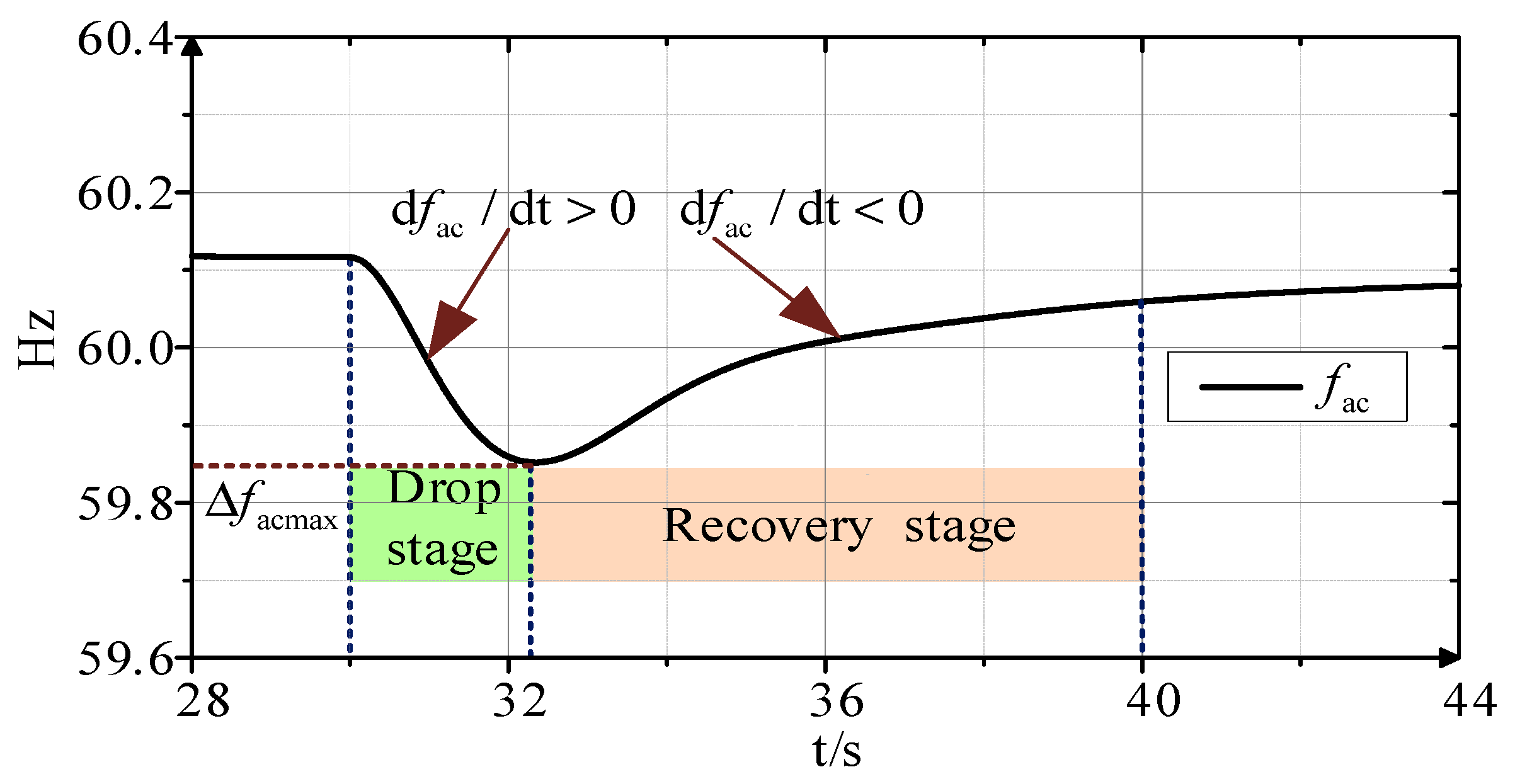
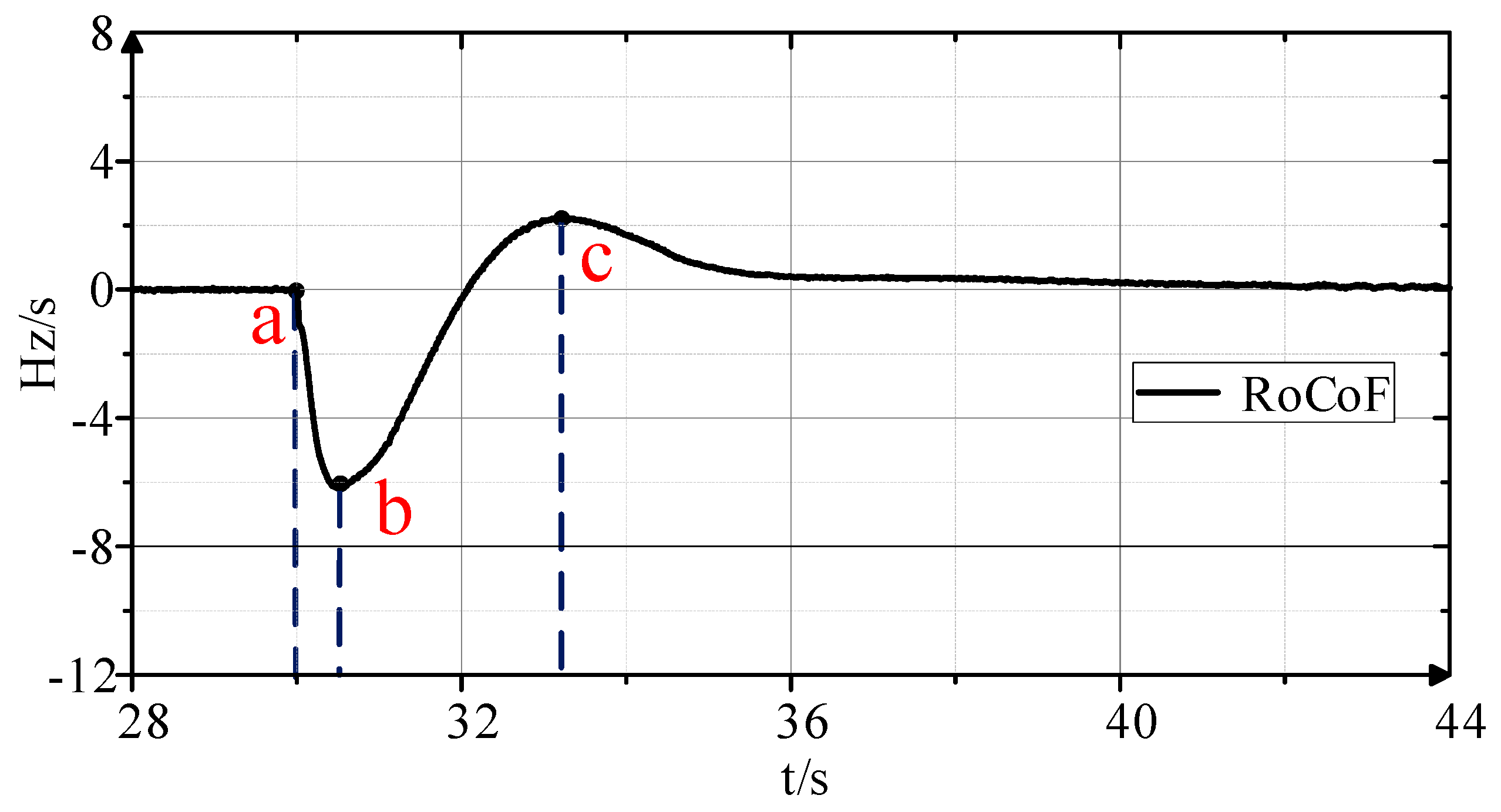
3.1. Analysis of the Frequency Recovery Requirement

When the power grid generates unbalanced power due to load fluctuations, the dynamic response of the system frequency becomes more satisfied if the active inertia provided by the MMC-HVDC can be adjusted autonomously in real time according to the actual frequency changes. But, in the traditional actual active inertia control of MMC, the inertia H of the synchro is constant and cannot be adjusted independently. Actually, the VSG control of MMC-HVDC can flexibly adjust system inertia by changing the control parameter H. Therefore, the response characteristics of the AC system 2 can be improved by adjusting the active inertia H in real time according to the dynamic frequency change. In order to obtain the linearized expression, the Taylor expansion of (11) is first carried out, and the higher order phase above the quadratic term is ignored.
U dc * = 1 + 4 H S B 3 C ph f acN U dcN 2 ( f ac f acN )
Taking the derivation of (12), it has
d U dc * dt = 4 H S B 3 C ph f acN U dcN 2 d f ac dt
It can be seen from (13) that in traditional MMC-HVDC active inertia control, the inertia constant H is usually a fixed value. Assuming that the AC power grid load fluctuation causes sudden power loss in a certain period of time, it can be obtained that the system frequency change rate d f ac / dt is proportional to the MMC-HVDC DC voltage change rate d U dc * / dt . Assuming that the system frequency drops due to load power fluctuation, the frequency response and frequency change rate response on the AC side are shown in Figure 4 and Figure 5.
From Figure 4 and Figure 5, the AC system 2 has load fluctuation at time a, resulting in a power difference. Under the influence of unbalanced power, the frequency of the AC system 2 initially enters a decreasing period. When it drops to the lowest point, the frequency change reaches its maximum. During this period, d f ac / dt < 0 and the energy stored in MMC releases for system inertia response. Subsequently, the system enters a recovery period where the frequency starts to increase, representing the absorption of energy and d f ac / dt > 0 . As shown in Figure 5, the absolute value of the rate of change d f ac / d t of the AC frequency decreases sharply at time a, and it first increases and then decreases. When the rate of change d f ac / d t reaches zero, it becomes positive. In stage a−b, the slope of d f ac / d t is k a b < 0 , and the frequency f ac is decreasing. Further, from (13), this stage requires a large active inertia time constant H to reduce the impact of the unbalanced power on the AC system 2. However, the active inertia time constant H cannot be too large since too much H can lead to a rapid rate of change in DC voltage, as indicated by (13). In stage b-c, the slope of d f ac / d t is k a - b > 0 , which indicates that the frequency of the AC system 2 starts to recover under the influence of active inertia. At this stage, a small active inertia time constant H is required to accelerate the recovery of the system frequency and reduce the impact on DC voltage. If the active inertia constant H is too large, it can lead to an increased frequency change rate at time c, which results in excessive DC voltage and negatively impacts system frequency stability.

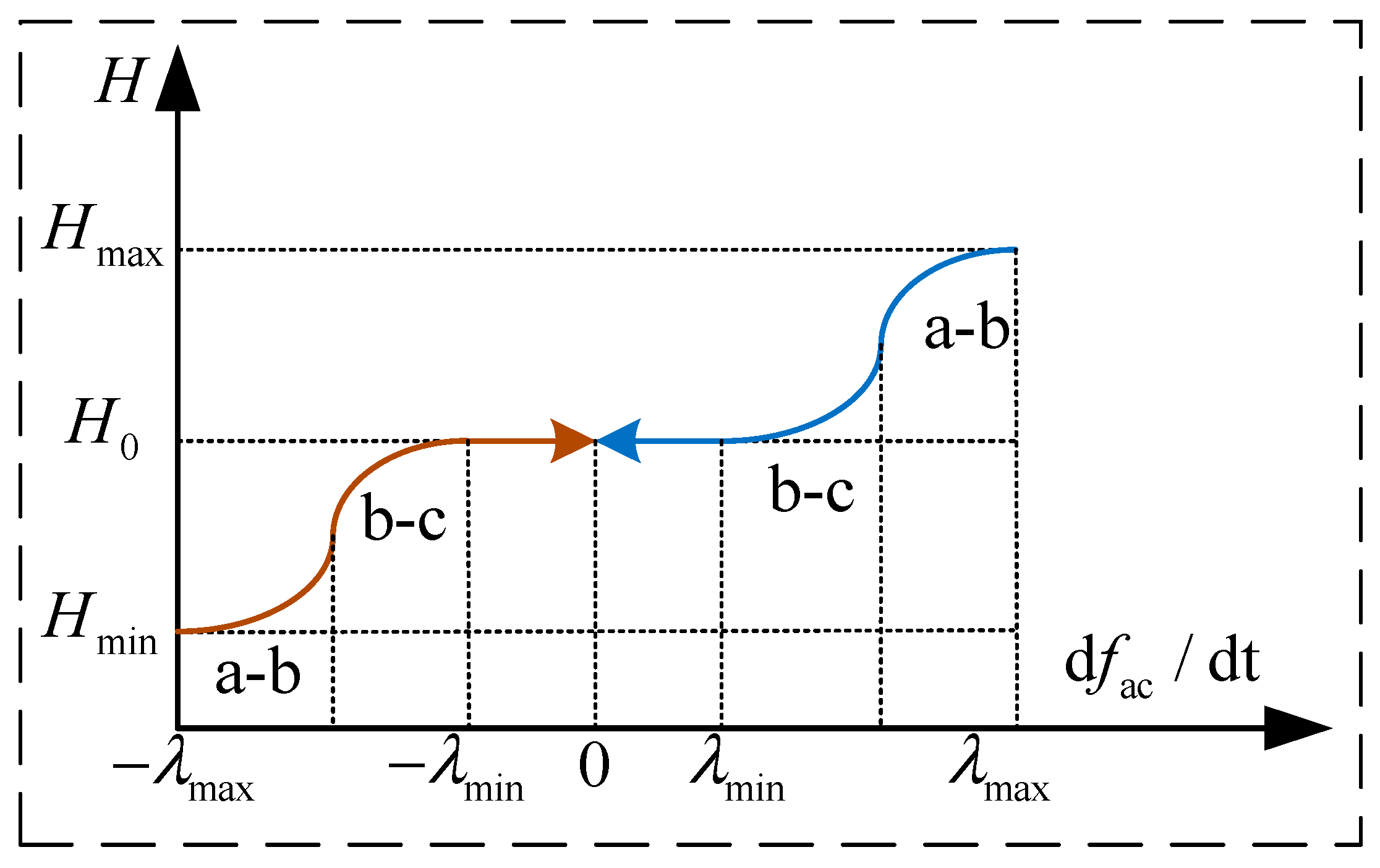
3.2. The Adaptive Active Inertia Control of MMC-HVDC

In order to enhance the dynamic response feature of MMC-HVDC with active inertia support, this paper considers the relationship of active inertia control constant H with power fluctuation and the frequency rate of the system and proposes an adaptive active inertia control strategy for MMC-HVDC system. By introducing a variation of the Sigmoid function with amplitude limiting capability, the active inertia control constant H can be dynamically adjusted according to the frequency change rate of the AC system 2. When the AC system 2 is disturbed by power fluctuation, the active inertia time constant H of for the MMC-HVDC can be given as follows:
H = H 0 λ min d f ac dt λ min β 1 1 + e μ ( 1 + e α d f ac dt ) + γ λ max < d f ac dt < λ min   or     λ min   < d f ac dt < λ max
where λ max and λ min are the starting threshold for adjusting the active inertia time constant H. The H0 is the active inertia time constant of MMC-HVDC within the threshold limit. The α , β , μ and γ are the adaptive control adjustment coefficients. In the four coefficients, the μ affects the rate of change of the inertia constant according to d f ac / dt . The β adjusts the maximum value of the controller output inertia constant. The α is the given coefficient that regulates the response speed of the controller. The γ is the minimum threshold of the inertia constant. Figure 6 shows the variation of inertia constant H with the change of frequency d f ac dt . In stage a-b, the rate of AC system 2 frequency is large, and a larger inertia constant H is needed to slow down the frequency changes in a faster manner. In stage b-c, the rate of AC system 2 frequency decreases, and small H is enough to support the frequency recovery, which can also prevent large fluctuations in the DC voltage of MMC-HVDC. Finally, the overall adaptive active inertia control diagram for MMC-HVDC systems is given in Figure 7. In Figure 7, v abc and i abc are the voltage and current of AC system 2, respectively. In reality, the proposed control strategy only needs to detect the frequency change of AC system 2 and then feed it back to MMC-HVDC control for the implementation of the proposed scheme.

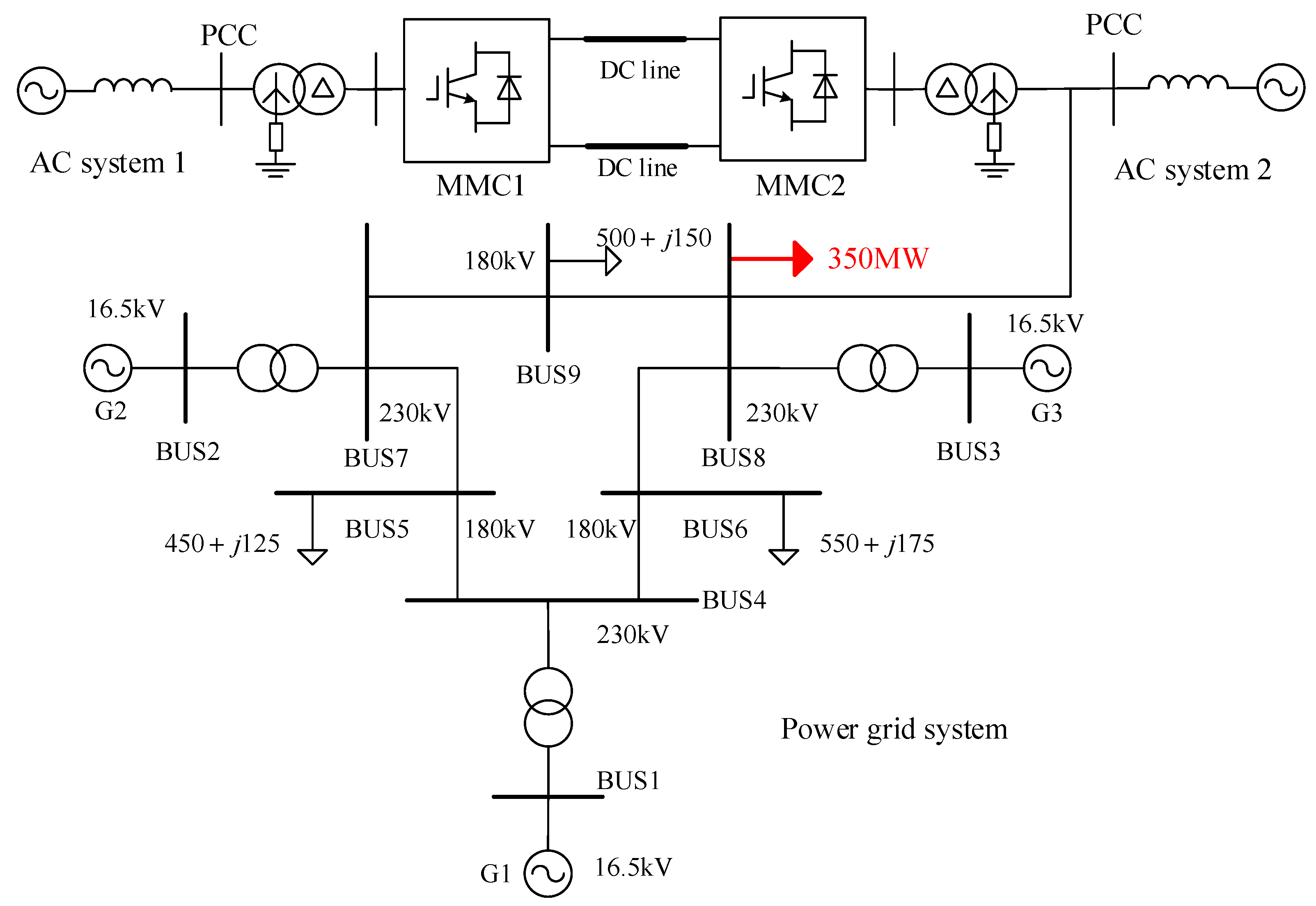
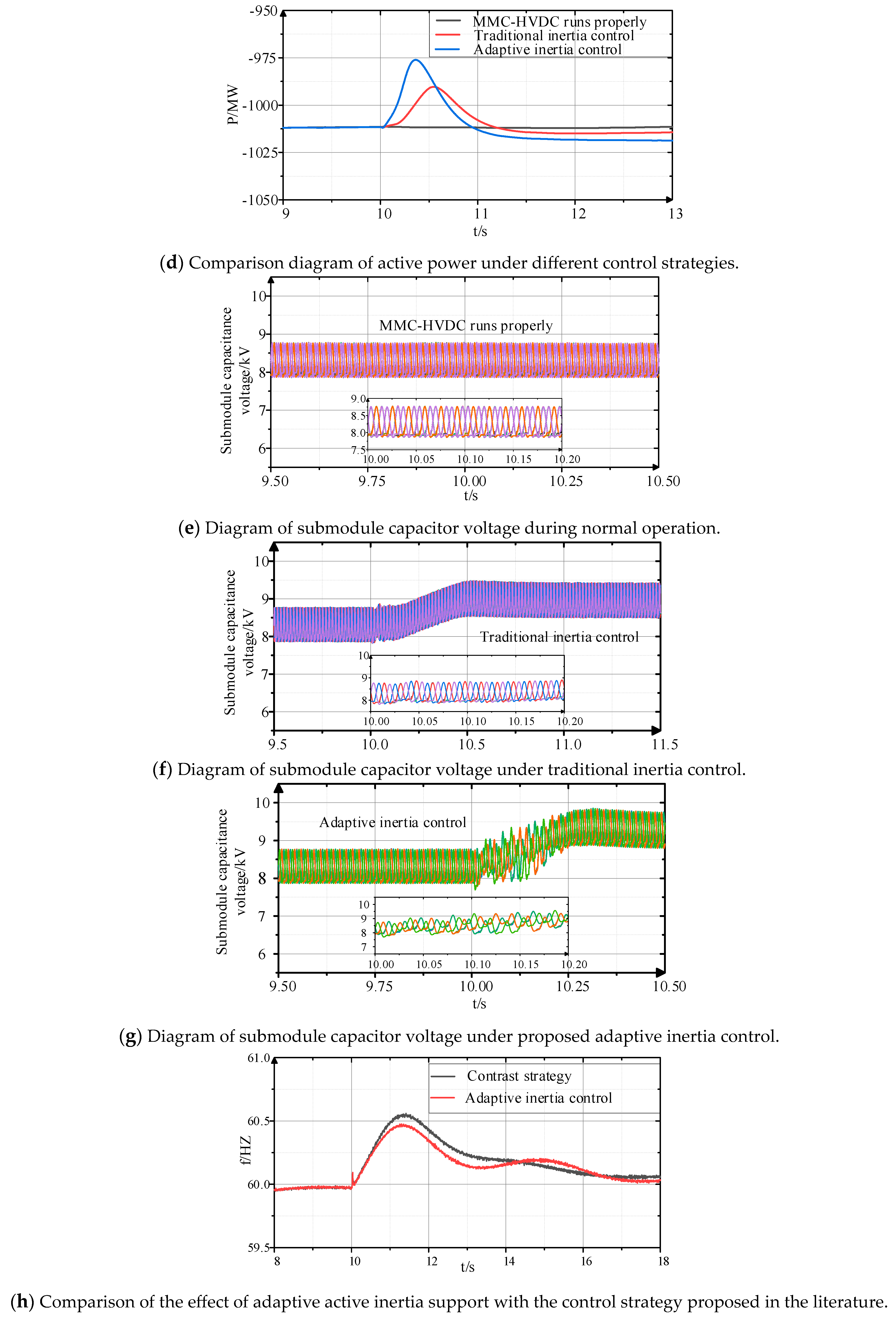
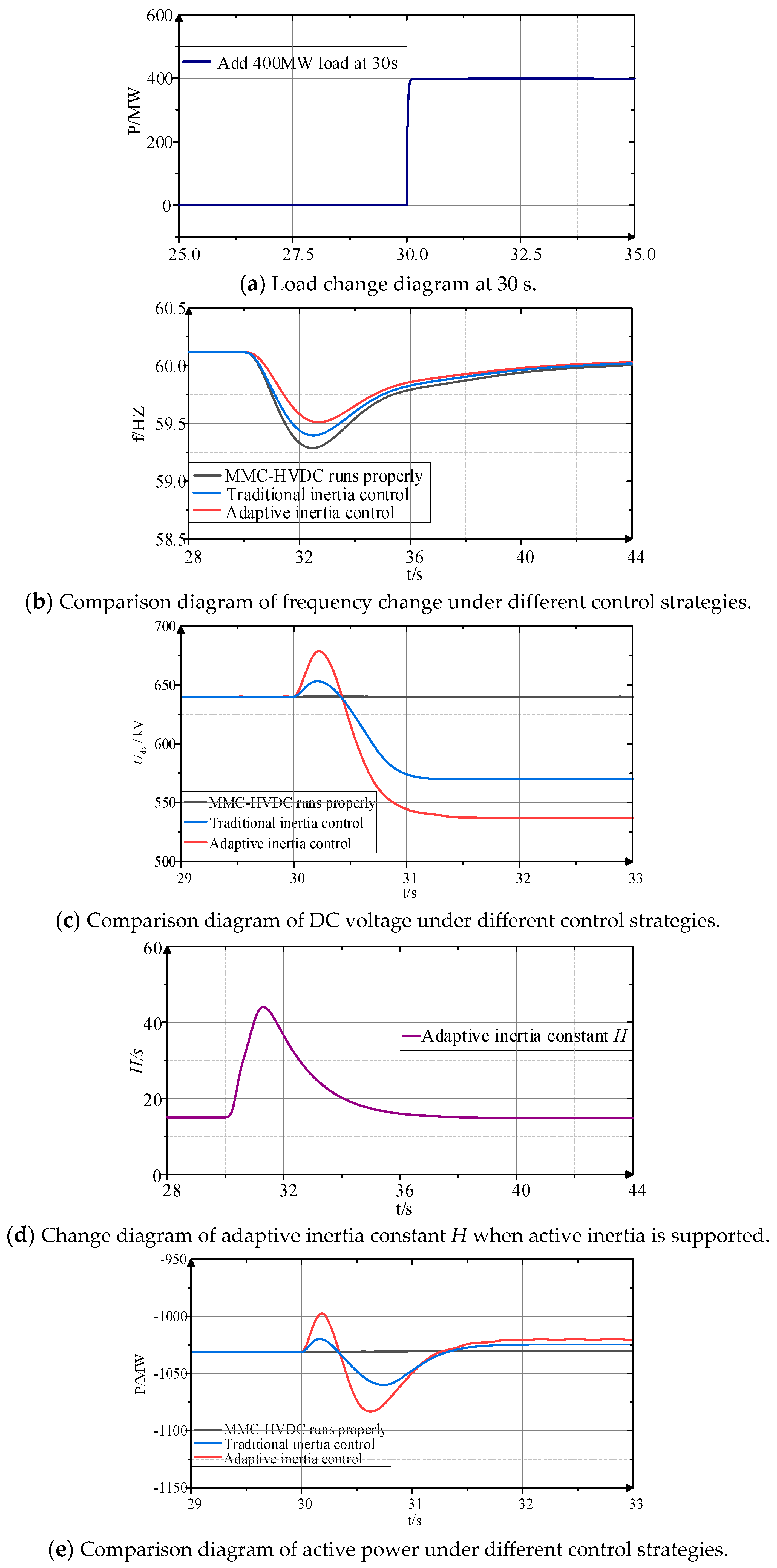
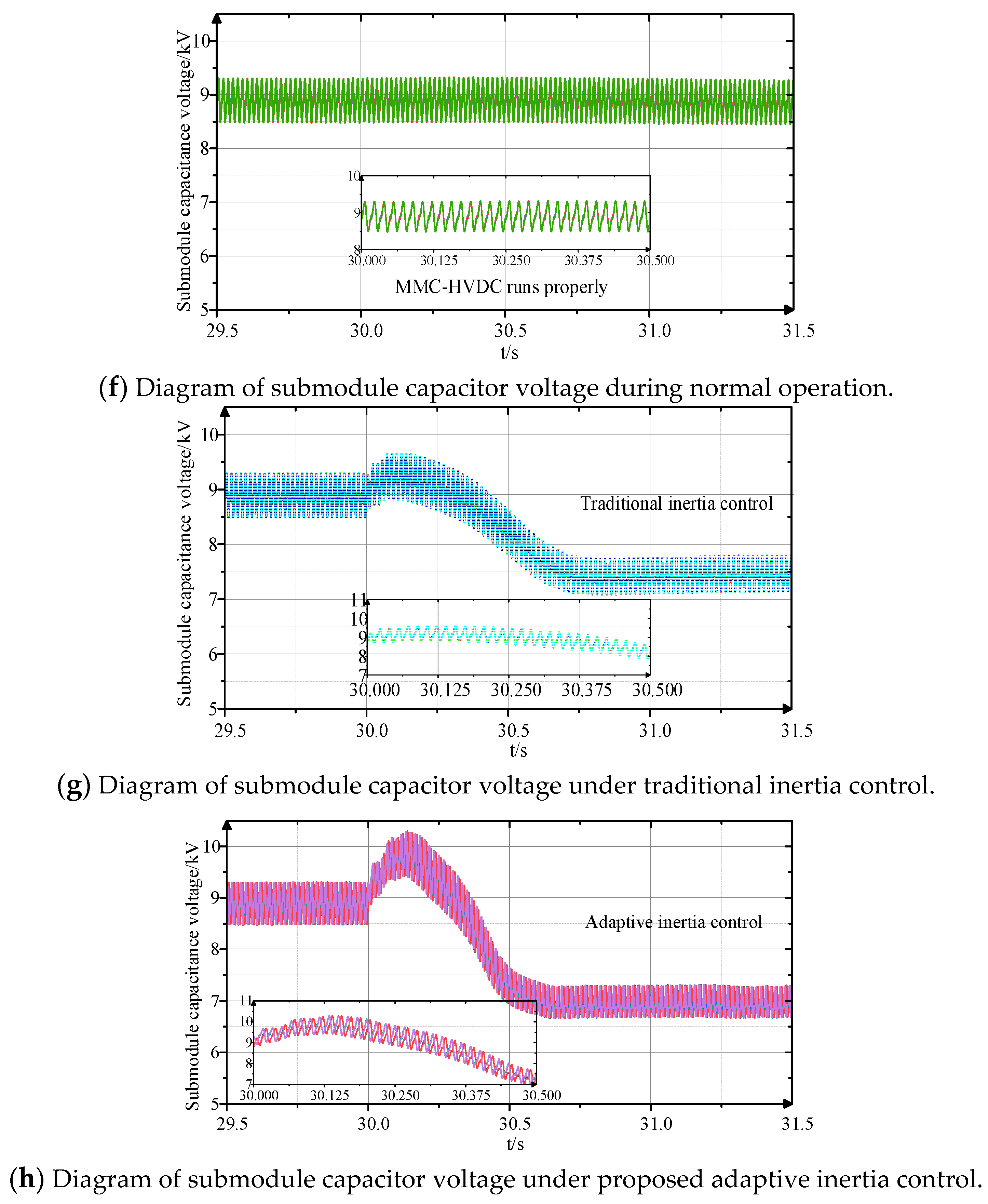
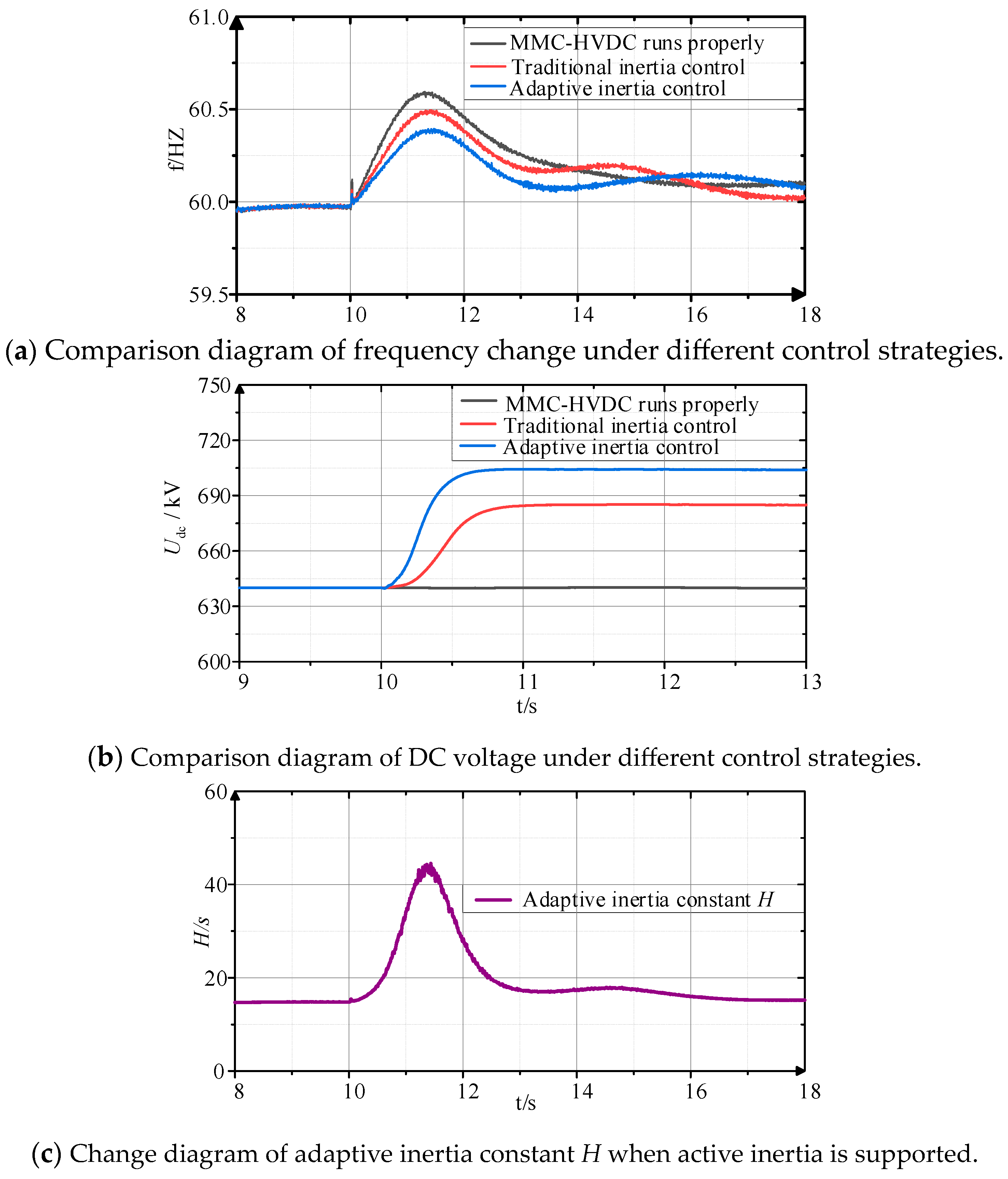
4. Simulation Analysis

A.
Case 1
In order to verify the effectiveness of the proposed adaptive active inertia control strategy, the dual terminal MMC-HVDC model is established in the PSCAD/EMTDC simulation platform, and the system key control parameters of the simulation model are shown in Table 1.
In this case, as shown in Figure 8, the load in AC system 2 increases by 400 MW at 30 s, and the AC frequency is supported by the proposed adaptive active inertia control strategy. In order to analyze the effectiveness of the proposed control strategy, the dynamic frequency response of the MMC-HVDC system under different inertia control strategies is compared. The simulation comparison results under different control strategies are shown in Figure 9. Here, MMC-HVDC runs properly, which indicates the normal operation of MMC-HVDC without providing any inertia support for the AC system.
The simulation results are shown in Figure 9. The load power of the AC system 2 is increased by 400 MW in 30 s. The dynamic responses of the AC system 2 frequency, DC voltage, active power and submodule capacitance voltage of the MMC-HVDC system under different control strategies are analyzed. The simulation results indicate that the transient response of the AC system 2 frequency and DC voltage varies with different control strategies. In Figure 9b,c, it is evident that the proposed adaptive inertia control strategy provides flexible inertia support to the AC grid during system disturbance. It can be seen from Figure 9b–d that the adaptive inertia control proposed in this paper can provide certain inertia support for the AC system 2 under disturbance. Compared with the traditional active inertia control strategy, when the frequency change rate is large, the adaptive inertia control can better respond to the frequency change by adaptively adjusting the virtual inertia constant H of the MMC-HVDC, so that the frequency response can be further improved. At the beginning of the disturbance, the MMC-HVDC has a rapidly increased inertia constant H due to the fast frequency change, which means more power support for the AC system 2 can be provided. After the frequency change decreases, the inertia constant H of the MMC-HVDC is gradually reduced in order to ensure the safe operation of the system. In the traditional active inertia control strategy, the AC system 2 frequency drops to 59.38 Hz, and the maximum Δ f ac is 0.62 Hz. However, after adopting adaptive inertia control of MMC-HVDC, the virtual inertia constant is flexibly increased when the frequency change rate is large, so as to provide more inertia support for AC system 2. The frequency of AC system 2 drops to 59.51 Hz, and the maximum Δ f ac increases to 0.49 Hz, which further improves the AC frequency response compared with the traditional active inertia control. Compared with traditional inertia control, the proposed control strategy reduces the frequency variation of AC system 2 by 21%. Figure 9e shows the MMC-HVDC active power variation diagram under different control strategies, as can be seen in that the proposed adaptive inertia control strategy provides more power support for AC system 2. Figure 9f–h shows the capacitance voltage response of the MMC-HVDC submodule under different control strategies. From Figure 9f, the DC voltage remains unchanged, and the capacitor voltage of the sub-module is stable at 8.8 kV. As shown in Figure 9g, when adopting the virtual inertia control strategy, the MMC-HVDC submodule capacitors provide active inertia support for AC system 2. Under the traditional inertia control strategy, the submodule capacitance reduces to 7.5 kV. Although the traditional inertia can also provide some inertia support for AC system 2, it cannot adjust the inertia constant according to the frequency change; thus, the supporting capacity is weak. As shown in Figure 9h, the MMC-HVDC submodule with the proposed adaptive inertia control provides more inertia for AC system 2, and the submodule capacitance voltage fluctuates to 6.8 kV. It should be noted that in Figure 9c, the DC voltage during 30-33 s is given. Since the frequency is still in a recovery process at 33 s, the DC voltage presents errors compared with the rated value. When the frequency returns to the steady state, the errors of DC voltage will be eliminated.
B.
Case 2
To further verify the effectiveness of the proposed strategy, the MMC-HVDC simulation model with a three-machine, nine-node network is established in PSCAD, as shown in Figure 10. The structural parameters of the model are shown in Table 2. The MMC-HVDC model in Case 2 is the same as that in Case 1; thus, the main parameters of the MMC-HVDC system do not change. As for the control parameters setting issue, the most important control parameters of the proposed scheme are the adaptive threshold λ min and λ max , as well as the exponential coefficient α . λ min and λ max determine the starting threshold for adjusting the active inertia time constant H, while the exponential coefficient α is the most important indicator that determines the response speed of the inertia time constant H. Therefore, in this case, these key control parameters are set, varying to conduct validation of the proposed control strategy. In the initial state, MMC-HVDC transmits 1000 MW to the receiving-end power grid. The output voltage of synchronous generators G1, G2 and G3 are 16.5 kV. The load of the entire network is 1500 MW, and the MMC-HVDC transmits 1000 MW of active power to the AC network. The surplus 500 MW of the load power is supplied by the three synchronous generators. In this case, the load power reduction of 350 MW is set at the AC bus BUS8 at 10 s. The proposed active inertia adaptive control strategy of MMC-HVDC provides certain support for AC frequency, and the simulation comparison results under different controls are shown in Figure 11.
The simulation results are shown in Figure 11. In Figure 11a, the AC frequency variation diagram of MMC-HVDC under different control strategies is given, while Figure 11b,c shows the variation of DC voltage and transmission power, respectively. Figure 11d shows the dynamic change of the inertia constant of the proposed adaptive active inertia support control strategy. The proposed control strategy adaptively adjusts the inertia constant of MMC-HVDC according to the frequency change of the power grid. As shown in Figure 11a, after a 350 MW load disturbance on the connected AC power grid, the maximum frequency variation is 0.59 Hz, when the MMC-HVDC provides no active inertia support. With the traditional active inertia support control strategy, the maximum variation of frequency is 0.48 Hz. When the adaptive inertia control strategy is adopted, the active support capability of MMC-HVDC can be increased, and the maximum frequency variation is improved to 0.37 Hz. Compared with traditional inertia control, the proposed control strategy reduces the frequency variation of AC system 2 by 23%. Figure 11e–g gives the submodule capacitance voltage response diagram of MMC-HVDC under different control strategies. When the MMC-HVDC provides no active inertia support for AC system 2, the sub-module capacitor voltage can be stable at 8.8 kV. As shown in Figure 11f, when the MMC-HVDC submodule capacitor is used to provide active inertia support for AC system 2 through traditional virtual inertia, the submodule capacitance is increased to 9 kV. As can be seen from Figure 11g, the proposed adaptive inertia control provides more inertia support for AC system 2, while the submodule capacitance voltage fluctuates to 9.4 kV. In order to verify the supporting effect of the proposed adaptive active inertia supporting control strategy, the strategy in Ref. [12] is also adopted here for comparison with the proposed scheme, and the frequency change of AC system 2 with the scheme in Ref. [12] shown in Figure 11h. It can be concluded that the control strategy proposed in this paper can provide the adaptive active adjustment ability of MMC-HVDC, and the frequency response of the system can be improved with superior performance. In a word, the two considered different simulation cases performed in this paper are sufficient to highlight the feasibility of the proposed method.

5. Conclusions

In order to effectively inhibit the change of AC frequency when the connected AC system is subjected to power disturbance and improve the active inertia support capability of the MMC-HVDC system, this paper presents an adaptive control strategy for active inertia support of MMC-HVDC systems. Through theoretical derivation and simulation analysis, the main conclusions of this paper are as follows:
(1) By analogy with the synchronous generator, the MMC-HVDC adaptive virtual inertia control strategy is proposed, which can effectively enhance the active inertia support capability of the MMC-HVDC system and improve the frequency response of the AC system.
(2) This paper constructs the adaptive control parameters by introducing a variation of the Sigmoid function with amplitude limiting capability. With the proposed adaptive scheme, the inertia constant H of the system is adjusted according to the frequency change rate of the AC system. The two simulation cases show that with the proposed control strategy, the maximum change of the AC system frequency is reduced by 21% and 23%, respectively. Therefore, the proposed control strategy has excellent frequency response characteristics, and the safe and stable operation ability of low inertia MMC-HVDC system is improved.
(3) The proposed MMC-HVDC adaptive active inertia control strategy can provide flexible inertia support for low inertia systems. The next research step can be focused on the active support capability of the MMC-HVDC systems with integration renewal energy.

Author Contributions

Conceptualization, Z.L. (Ziwen Liu) and Z.L. (Zhaoxia Li); methodology, X.L. and J.W.; validation, X.L., Z.Z. and J.W.; writing—original draft preparation, X.L. and J.W; writing—review and editing, Z.L. (Ziwen Liu) and Z.L. (Zhaoxia Li); visualization, X.L. and Z.Z; funding acquisition, Z.L. (Zhaoxia Li). All authors have read and agreed to the published version of the manuscript.

Funding

The work was funded by a project of the Tibet Science and Technology Department of Tibet Guided by the Central Government. Project Number: (XZ202201YD0022C).

Data Availability Statement

Not applicable.

Conflicts of Interest

The authors declare no conflict of interest.

References

  1. Catalán, P.; Wang, Y.; Arza, J.; Chen, Z. A Comprehensive Overview of Power Converter Applied in High-Power Wind Turbine: Key Challenges and Potential Solutions. IEEE Trans. Power Electr. 2023, 38, 6169–6195. [Google Scholar] [CrossRef]
  2. Van Aarde, P.; Dalton, A.; Bekker, B. Balancing wind and solar power variability through spatial deployment informed by weather regimes: A review and roadmap ahead. In Proceedings of the 2022 30th Southern African Universities Power Engineering Conference (SAUPEC), Durban, South Africa, 25–27 January 2022; pp. 1–6. [Google Scholar]
  3. Debnath, S.; Chinthavali, M. Control of MMC-HVDC in low-inertia weak grids. In Proceedings of the 2017 IEEE 12th International Conference on Power Electronics and Drive Systems (PEDS), Honolulu, HI, USA, 12–15 December 2017; pp. 435–441. [Google Scholar]
  4. Liu, Z.; Lv, X.; Wu, F.; Li, Z. Multi-Mode Active Inertia Support Strategy for MMC-HVDC Systems Considering the Constraint of DC Voltage Fluctuations. IEEE Trans. Power Deliver. 2023, 38, 2767–2781. [Google Scholar] [CrossRef]
  5. Tu, L.; Yang, Y.; Yang, J.; Sun, T. The Synthetic Inertia Controller for MMC-HVDC Based Offshore Wind Farm Integration. In Proceedings of the 2021 IEEE 1st International Power Electronics and Application Symposium (PEAS), Shanghai, China, 13–15 November 2021; pp. 1–4. [Google Scholar]
  6. Roy, N.K.; Islam, S.; Podder, A.K.; Roy, T.K.; Muyeen, S.M. Virtual Inertia Support in Power Systems for High Penetration of Renewables—Overview of Categorization, Comparison, and Evaluation of Control Techniques. IEEE Access 2022, 10, 129190–129216. [Google Scholar] [CrossRef]
  7. Cui, F.; Zang, B. Adaptive Control Strategy for Moment of Inertia and Damping Coefficient of Virtual Synchronous Generator. In Proceedings of the 2022 4th International Conference on Power and Energy Technology (ICPET), Beijing, China, 28–31 July 2022; pp. 193–197. [Google Scholar]
  8. Wang, Z.; Yu, Y.; Gao, W.; Davari, M.; Deng, C. Adaptive, Optimal, Virtual Synchronous Generator Control of Three-Phase Grid-Connected Inverters Under Different Grid Conditions—An Adaptive Dynamic Programming Approach. IEEE Trans. Ind. Inform. 2022, 18, 7388–7399. [Google Scholar] [CrossRef]
  9. Fan, W.; Yan, X.; Hua, T. Adaptive parameter control strategy of VSG for improving system transient stability. In Proceedings of the 2017 IEEE 3rd International Future Energy Electronics Conference and ECCE Asia (IFEEC 2017—ECCE Asia), Kaohsiung, Taiwan, 3–7 June 2017; pp. 2053–2058. [Google Scholar]
  10. Li, J.; Wen, B.; Wang, H. Adaptive Virtual Inertia Control Strategy of VSG for Micro-Grid Based on Improved Bang-Bang Control Strategy. IEEE Access 2019, 7, 39509–39514. [Google Scholar] [CrossRef]
  11. Xie, Y.; Xie, Z.; Chang, Y.; Zhang, L. Virtual Inertia Adaptive Control Strategy for DFIG Wind Turbines Based on the Improved Bang-Bang Control. In Proceedings of the 2020 IEEE 9th International Power Electronics and Motion Control Conference (IPEMC2020—ECCE Asia), Nanjing, China, 29 November–2 December 2020; pp. 1935–1940. [Google Scholar]
  12. Zhai, B.; Wei, W.; Shi, Y.; Chen, G.; Sun, R.; Gao, B. Adaptive virtual inertia control-based frequency support method for photovoltaic penetrated power system. In Proceedings of the 2021 IEEE Sustainable Power and Energy Conference (iSPEC), Nanjing, China, 23–25 December 2021; pp. 157–162. [Google Scholar]
  13. Wang, Q.; Zhou, D.; Yin, S.; Lei, Y.; He, T. Improved Adaptive Inertia and Damping Coefficient Control Strategy of VSG Based on Optimal Damping Ratio. In Proceedings of the 2022 International Power Electronics Conference (IPEC-Himeji 2022—ECCE Asia), Himeji, Japan, 15–19 May 2022; pp. 102–107. [Google Scholar]
  14. Saxena, A.; Shankar, R.; Al Zaabi, O.; Al Hosani, K.; Muduli, U.R. Fuzzy Rule-based Adaptive Virtual Inertia Control for Enhancing Multi-Region Micro-grid Dynamic Response. In Proceedings of the 2023 IEEE IAS Global Conference on Renewable Energy and Hydrogen Technologies (GlobConHT), Male, Maldives, 11–12 March 2023; pp. 1–6. [Google Scholar]
  15. Guo, C.; Xu, L.; Yang, S.; Jiang, W. A Supplementary Damping Control for MMC-HVDC System to Mitigate the Low-Frequency Oscillation Under Low Inertia Condition. IEEE Trans. Power Deliver. 2023, 38, 287–298. [Google Scholar] [CrossRef]
  16. Song, J.; Gao, X.; Sun, H.; Guo, W. Improved Virtual Inertia Damping Adaptive VDG Control Strategy for DC Microgrid Hybrid Energy Storage Converter. In Proceedings of the 2022 4th International Conference on Electrical Engineering and Control Technologies (CEECT), Shanghai, China, 16–18 December 2022; pp. 1188–1192. [Google Scholar]
  17. Zhang, Y.; Sun, Q.; Zhou, J.; Guerrero, J.M.; Wang, R.; Lashab, A. Optimal Frequency Control for Virtual Synchronous Generator Based AC Microgrids via Adaptive Dynamic Programming. IEEE Trans. Smart Grid 2023, 14, 4–16. [Google Scholar] [CrossRef]
  18. Mengxue, D.; Zhisong, L.; Wei, X.; Xiaoyu, Z.; Jianyu, L. Research on Adaptive Control of Virtual Synchronous Generator. In Proceedings of the 2020 IEEE 4th Information Technology, Networking, Electronic and Automation Control Conference (ITNEC), Chongqing, China, 12–14 June 2020; pp. 1169–1174. [Google Scholar]
  19. Tan, X.; Ren, L.; Tang, Y.; Li, J.; Shi, J.; Xu, Y.; Sheng, C.; Xiao, L. Comparative Analysis of Three Types of SFCL Considering Current-Limiting Requirement of MMC-HVDC System. IEEE Trans. Appl. Supercon. 2021, 31, 1–5. [Google Scholar] [CrossRef]
  20. Chen, S.; Zhang, X.; Wu, Y.; Zhu, Q.; Bao, C.; Zhan, X. Segmented Adaptive Control of Virtual Inertia for Virtual Synchronous Machines. In Proceedings of the 2022 7th International Conference on Power and Renewable Energy (ICPRE), Shanghai, China, 23–26 September 2022; pp. 176–181. [Google Scholar]
  21. AziziAghdam, S.; Agamy, M. Small Signal Stability Analysis of Dispatchable Virtual Oscillator Controlled Inverters with Adaptive Virtual Inertia Control. In Proceedings of the 2023 IEEE Power & Energy Society Innovative Smart Grid Technologies Conference (ISGT), Washington, DC, USA, 16–19 January 2023; pp. 1–5. [Google Scholar]
  22. Liang, J.; Chen, L.; Li, T.; Feng, H.; Zeng, S.; Li, X. VSG Integrated Control Strategy Based on Hamilton Theory. In Proceedings of the 2021 IEEE/IAS Industrial and Commercial Power System Asia (I&CPS Asia), Chengdu, China, 18–21 July 2021; pp. 885–891. [Google Scholar]
  23. Kang, Z.; Zhao, B.; Zhao, Z.; Zhang, Z.; Wang, S.; Yu, H. In Proceedings of the Passivity-Based Control Strategy of MMC-HVDC with Wind Farm Based on ESO and TSMC. In Proceedings of the 16th IET International Conference on AC and DC Power Transmission (ACDC 2020), Virtual, 2–3 July 2020; pp. 19–25. [Google Scholar]
  24. Bin, L.; Zhang, W. Virtual inertia control and voltage support in MMC-based DC systems. In Proceedings of the 2017 China International Electrical and Energy Conference (CIEEC), Beijing, China, 25–27 October 2017; pp. 436–440. [Google Scholar]
  25. Zeng, W.; Li, R.; Huang, L.; Liu, C.; Cai, X. Approach to Inertial Compensation of HVDC Offshore Wind Farms by MMC With Ultracapacitor Energy Storage Integration. IEEE Trans. Ind. Electron. 2022, 69, 12988–12998. [Google Scholar] [CrossRef]
  26. Liu, Z.; Wang, Y.; Lai, J.; Zheng, A. Markov-Based Stochastic Stabilization Control for MMC-HVDC Systems with Inertia Supporting Under Random Disturbances. IEEE Trans. Power Syst. 2023, 1–12. [Google Scholar] [CrossRef]
  27. Li, G.; Gao, J.; Liu, X.; Li, W.; Li, Z.; Qi, W.; Yu, H. A Frequency Prevention and Control Method of MMC-HVDC Connected to Passive Power Grid Considering DC Capacitor Energy Buffer. In Proceedings of the 2021 IEEE Sustainable Power and Energy Conference (iSPEC), Nanjing, China, 23–25 December 2021; pp. 2929–2934. [Google Scholar]
  28. Chu, J.; Lv, Y.; Xu, Y.; Du, G.; Sun, D.; Yu, P. Coordinated Control Strategy for Improving Frequency Stability of Offshore Wind Farms Connected to the Grid through MMC–HVDC Transmission. In Proceedings of the 2022 4th Asia Energy and Electrical Engineering Symposium (AEEES), Chengdu, China, 25–28 March 2022; pp. 354–360. [Google Scholar]
  29. Yang, R.; Shi, G.; Zhang, C.; Li, G.; Cai, X. Internal Energy Based Grid-Forming Control for MMC-HVDC Systems With Wind Farm Integration. IEEE Trans. Ind. Appl. 2023, 59, 503–512. [Google Scholar] [CrossRef]
  30. Hirsching, C.; Goertz, M.; Wenig, S.; Bisseling, A.; Suriyah, M.; Leibfried, T. On Fault-Ride-Through Performance in MMC-HVDC Applications Controlled as a Virtual Synchronous Machine. IEEE Trans. Energy Conver. 2022, 37, 2803–2812. [Google Scholar] [CrossRef]
Figure 1. Typical MMC-HVDC system architecture model.
Electronics 12 04288 g001
Figure 2. Basic structure topology of modular multilevel converter.
Electronics 12 04288 g002
Figure 3. MMC-HVDC active inertia control block diagram.
Electronics 12 04288 g003
Figure 4. Response diagram of the frequency response during the load fluctuation.
Electronics 12 04288 g004
Figure 5. Diagram of frequency rate of change during the load fluctuation.
Electronics 12 04288 g005
Figure 6. Adaptive change diagram of active inertia time constant.
Electronics 12 04288 g006
Figure 7. MMC-HVDC active inertia adaptive control diagram.
Electronics 12 04288 g007
Figure 8. Typical MMC-HVDC system simulation model.
Electronics 12 04288 g008
Figure 9. Simulation results under different control strategies.
Electronics 12 04288 g009aElectronics 12 04288 g009b
Figure 10. Simulation model of MMC-HVDC systems in case 2.
Electronics 12 04288 g010
Figure 11. Simulation results under different control strategies in case 2.
Electronics 12 04288 g011aElectronics 12 04288 g011b
Table 1. The simulation parameters for MMC-HVDC.
ParameterNumerical Value
DC voltage/kV640
Rated capacity/MW1200
Arm submodules number76
Submodule capacity/μF2800
AC frequency/Hz60
Normal active inertia threshold15
Active inertia adaptive d f ac / dt threshold λ min and λ max 0.2, 0.8
Adaptive control adjustment coefficients μ , α , β , γ −0.02, −1, 20, 15
Table 2. The Simulation parameters of MMC-HVDC in case 2.
ParameterNumerical Value
DC voltage/kV640
Rated capacity/MW1200
Arm submodules number76
Submodule capacity/μF2800
AC frequency/Hz60
Normal active inertia threshold15
Active inertia adaptive d f ac / dt threshold threshold λ min and λ max 0.35, 0.95
Adaptive control adjustment coefficients μ , α , β , γ −0.02,−1.5,20,15
Disclaimer/Publisher’s Note: The statements, opinions and data contained in all publications are solely those of the individual author(s) and contributor(s) and not of MDPI and/or the editor(s). MDPI and/or the editor(s) disclaim responsibility for any injury to people or property resulting from any ideas, methods, instructions or products referred to in the content.

